

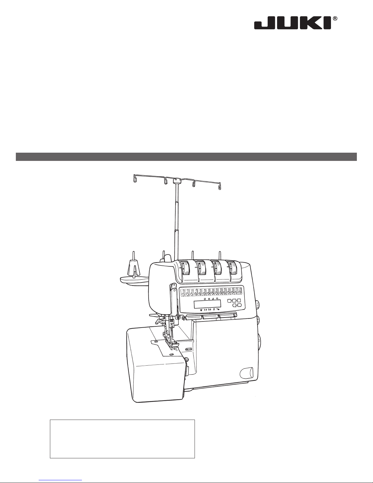
MO-2000QVP
2-Needle, 2/3/4-Thread Overlock Sewing Machine
IMPORTANT:
Read all safety regulations carefully and understand
them before using your sewing machine.
Retain this instruction manual for future reference.
INSTRUCTION MANUAL

1
“IMPORTANT SAFETY INSTRUCTIONS”
When using an electrical appliance, basic safety precautions should always be followed, including
the following: Read all instructions before using this sewing machine.
“DANGER
___ To reduce the risk of electric shock:”
1. The appliance should never be left unattended when plugged in.
2.
Always unplug this appliance from the electric outlet immediately after using and before cleaning.
“WARNING
___ To reduce the risk of burns, re, electric shock, or injury to persons:”
1. Do not use the appliance as a toy. Caution is advised when the appliance is used by children, or
near children. This sewing machine can be used by children aged from 8 years and above and
persons with reduced physical, sensory or mental capabilities or lack of experience and knowledge if they have been given supervision or instruction concerning use of the sewing machine
in a safe way and understand the hazards involved. Children shall not play with the sewing machine. Cleaning and user maintenance shall not be made by children without supervision.
2. Use this appliance only for its intended use as described in this manual. Use only attachments
recommended by the manufacturer as contained in this manual.
3. Never operate this appliance if it has a damaged cord or plug, if it is not working properly, if it
has been dropped or damaged, or dropped into water. Return the appliance to the nearest authorized dealer or service center for examination, repair, electrical or mechanical adjustment.
4. Never operate the appliance with any air openings blocked. Keep ventilation openings of the
sewing machine and foot control free from the accumulation of lint, dust, and loose cloth.
5.
Keep ngers away from all moving parts. Special care is required around the sewing machine needle.
6. Always use the proper stitch plate. The wrong plate can cause the needle to break.
7. Do not use bent needles.
8. Do not pull or push fabric while stitching. It may deect the needle causing it to break.
9. Do not carry out sewing with a marking pin stuck in the material since doing so can cause knife/
needle breakage. In addition, do not attempt to cut anything other than fabric and thread with
the upper/lower knives.
10. Switch the sewing machine off “O” when making any adjustments in the needle area, such as
threading needle, changing needle, threading looper, or changing presser foot and the like.
11. Always unplug the machine from the electrical outlet when removing covers, when covers are
opened to thread the loopers, when lubricating or when making any other user servicing adjustments mentioned in the instruction manual.
12. Never drop or insert any object into any opening.
13. Do not use outdoors.
14.
Do not operate where aerosol (spray) products are being used or where oxygen is being administered.
15. To disconnect, turn all controls to the off “O” position, then remove plug from outlet.
16. Do not unplug by pulling on cord. To unplug, grasp the plug, not the cord.
17. Basically, the machine should be disconnected from the electricity supply when not in use.
18. If the power cord of this appliance is damaged, it must be replaced with a special cord by your
nearest authorized dealer or service center.
19. (Except USA/Canada) This machine is provided with double insulation.
Use only identical replacement parts. See instructions for servicing Double-Insulated machine.
“SERVICING DOUBLE-INSULATED PRODUCTS
(Except USA / Canada)”
In a double-insulated product, two systems of insulation are provided instead of grounding. No
grounding means is provided on a double-insulated product nor should a means for grounding be
added to the product. Servicing a double-insulated product requires extreme care and knowledge
of the system and should only be done by qualied service personnel. Replacement parts for a
double-insulated product must be identical to those parts in the product. A double-insulated product
is marked with the words DOUBLE INSULATION or DOUBLE INSULATED.
The symbol
may also be marked on the product.
“SAVE THESE INSTRUCTIONS”
“This overlock sewing machine is intended for household use only.”
2
Danger
warning
which is not
specied
There is a
risk of electrical shock
There is a
risk of re
There is a
risk of injury to hands,
etc.
Prohibited matter
which is not
specied
Disassem-
bly/alteration
is prohibited
Do not
place ngers under
the needle
Do not pour
oil, etc.
Generally
required
behavior
Disconnect
the power
plug
Congratulations on your purchase of a JUKI sewing machine.
Please be sure to read safety precautions in “To use the sewing machine safely” in the Instruction
Manual before use to fully understand the functions and operating procedures of the sewing machine so as to use the sewing machine for a long time.
After you have read the Instruction Manual, please be sure to keep it together with the warranty so
that you can read it whenever necessary.
To use the sewing machine safely
Marks and pictographs included in the Instruction Manual and shown on the sewing machine are
used so as to ensure safe operation of the sewing machine and to prevent possible risk of injury to
the user and other people.
Warning marks are used for different purposes as described below.
WARNING
Indicates that there is a possible risk of death or serious injury if this
mark is ignored and the sewing machine is used in a wrong manner.
CAUTION
Indicates the operation, etc. which can cause a possible risk of personal injury and/or physical damage if this mark is ignored and the sewing
machine is used in a wrong manner.
Pictographs mean the following:
3
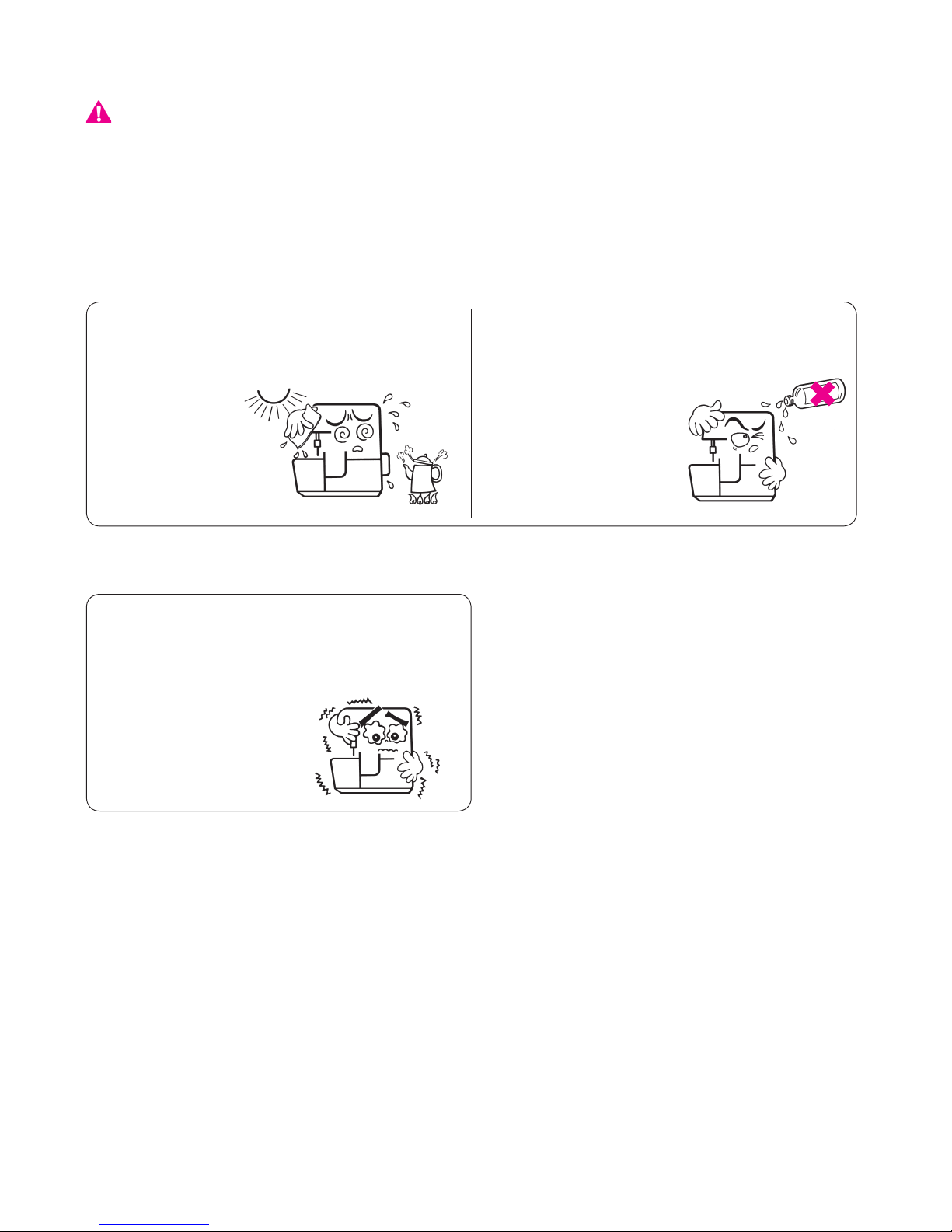
● Do not wipe the sewing machine with solvent
such as thinner.
When the sewing
machine is soiled, put
a small quantity of
neutral detergent on a
piece of soft cloth and
carefully wipe off the
sewing machine with it.
● Be sure to use the sewing machine in the
temperature range from 5ºC to 40ºC.
If the temperature is excessively low, the
machine can fail to operate normally.
WARNING
For the combination of the material and the thread and needle, in particular, refer to the explanation
table in “Replacement of the needle”.
If the needle or thread does not match the material used such as in the case that an extra heavyweight material (e.g., denim) is sewn with a thin needle (#11 or higher), the needle can break resulting in an unexpected personal injury.
Other precautions
● Do not put the sewing machine under the
direct sunlight or in a humid place.
Be aware that the following state can take place since the sewing machine incorporates semi-conductor electronic parts and precise electronic circuits.
* The operating temperature of the sewing machine is between 5ºC and 40ºC. Do not use the sew-
ing machine under the direct sunlight, near the burning things such as a stove and candle, or in a
humid place. By so doing, the temperature in the interior portion of the sewing machine can rise or
the coating of the power cord can melt, causing re or electrical shock.

4
Safety regulations ·································· 1-3
Contents··················································4
Details of the machine ····························· 5-7
• Accessories ·········································· 6
• Thread stand ·········································7
Preparing the machine / Using the machine · 7,8
• Attaching the foot control ··························7
• Waste collector ······································8
• Thread, cones, spools ·····························8
Using the machine
• Main Power/ light switch ···························9
• Looper cover ·········································9
• Handwheel ············································9
• Two step presser foot lifter ······················ 10
• Changing the presser foot ······················ 10
• Upper knife is deactivated ······················ 10
• How to use the presser foot ···················· 11
• Inserting needles /
Needles and Threads ······················· 11, 12
Adjustments and settings
• Stitch length ········································ 13
• Cutting width ······································· 13
• Differential feed ···································· 14
• Gathering ············································ 15
• Roll hemming ······································ 15
• Presser foot pressure ···························· 15
Setting/ Practical sewing
• Preparation/Tips ··································· 16
Threading 4/3 Thread OL
• Lower looper ······································· 17
• Upper looper ······································· 18
• Right needle ········································ 19
• Left needle ·········································· 20
• How to use the looper threader ················ 21
Trial sewing ············································ 22
Thread tension ······································· 23
Practical Sewing-Overlock
• Sewing in tape ····································· 24
• Carrying out hemming and narrow
overlocking ········································· 24
• Wrapped overlocking with three threads ···· 25
• 2-/3-thread changeover attachment ·········· 25
• Cover stitch with three threads (atlock) ···· 26
• Thread breakage during sewing ··············· 26
• Unpicking seams ·································· 26
Securing thread ends at the beginning and
end of sewing ···································· 27, 28
LCD indication ····································29-32
Stitch chart············································· 33
Maintenance
• Cleaning and lubricating ························· 34
• Replacing the knife ······························· 34
Trouble shooting guide ························ 35, 36
Technical data ········································ 37
Optional accessories ································ 37
Contents
5
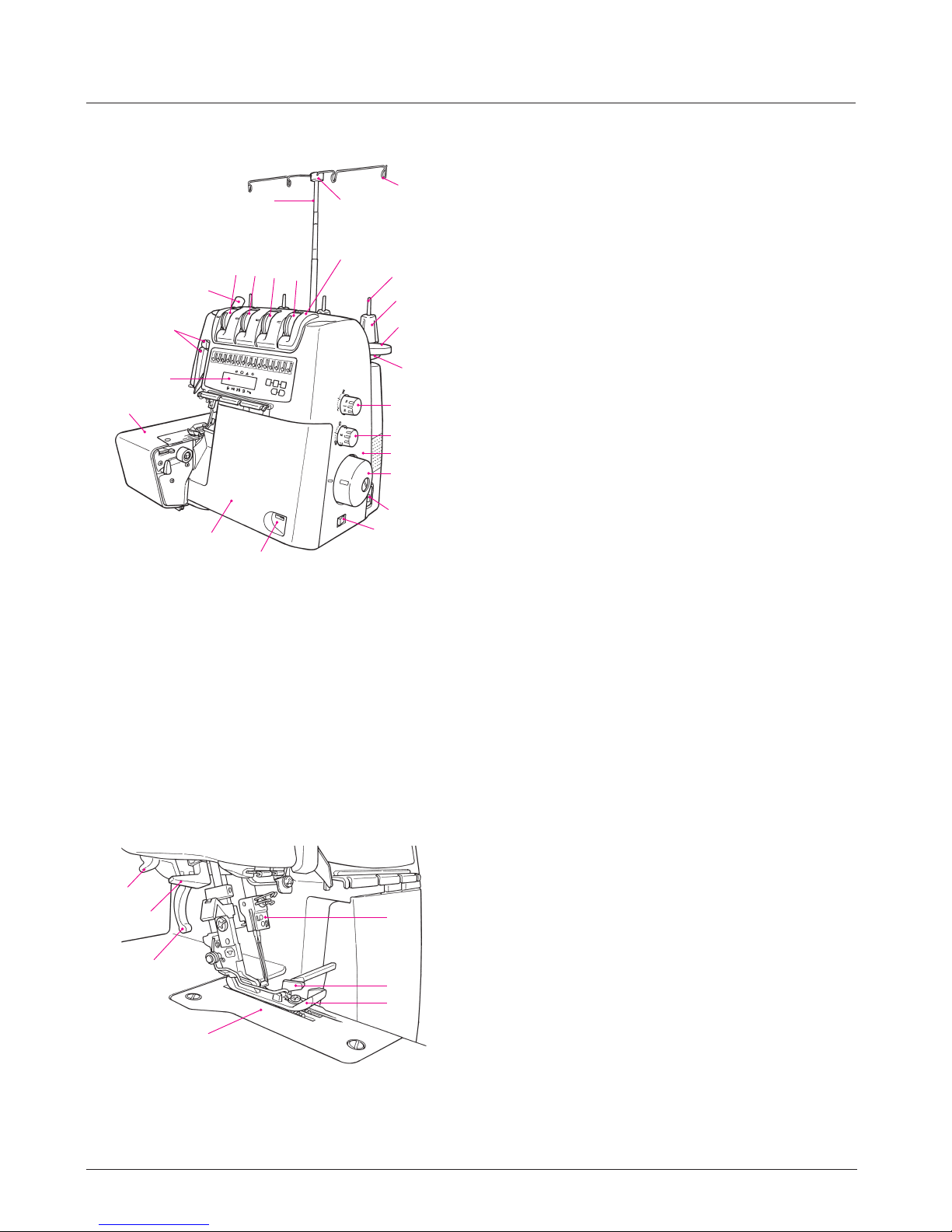
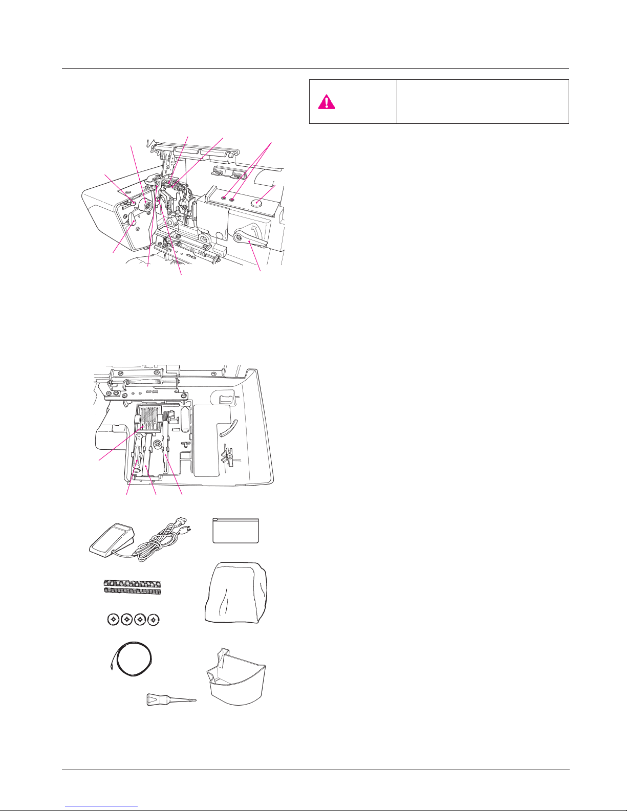
Details of the machine
Details of the machine
1. Looper cover with built in knife guard
2. Looper cover opening indent
3. Cloth plate
4. Top cover
5. Thread take-up cover
6. Presser foot pressure regulating knob
7. Left needle thread tension dial
8. Right needle thread tension dial
9. Upper looper thread tension dial
10. Lower looper thread tension dial
11. Retractable support rod
12. Thread guide support
13. Open thread guide
14. Spool holder pin
15. Foam pad
16. Anti - vibration cone
17. Thread stand
18. Stitch length adjustment dial
19. Differential feed adjustment dial
20. Handwheel
21. Front cover
22. Machine socket
23. Main Power/Light switch
24. LCD screen
6
12
11
5
13
15
23
17
14
16
18
19
21
3
20
22
1
2
4
10
8
9
7
24
Details of the machine
1. Thread cutter
2. Automatic needle threader
3. Presser foot lifter
4. Stitch plate
5. Presser foot
6. Upper knife
7. Needle clamp
1
3
4
7
6
5
2
6
Details of the machine
View with looper cover open
1. Selection lever for overlocking or roll hemming
2. Cutting width adjusting dial
3. Upper looper
4. Lower looper
5. Threading hole
6. Air-control pushbutton
7. Threading changeover lever
8. Upper knife xing screw
9. Lower knife
10. Upper knife changeover knob
Caution:
Be sure to turn off the power
switch before opening the looper
cover.
10
1
9
3
4
8
2
6
5
7
Accessories
1. Needle set 130/705H (SCHMETZ)
2. Screwdriver
3. Tweezers
4. Brush/needle inserter
5. Electronic foot control
6. Nets
7. Spool caps
8. Looper threader
9. Accessory bag
10. Dust cover
11. Waste collector
12. Oiler
5
4
6
10
2
3
9
1
11
7
8
12
7
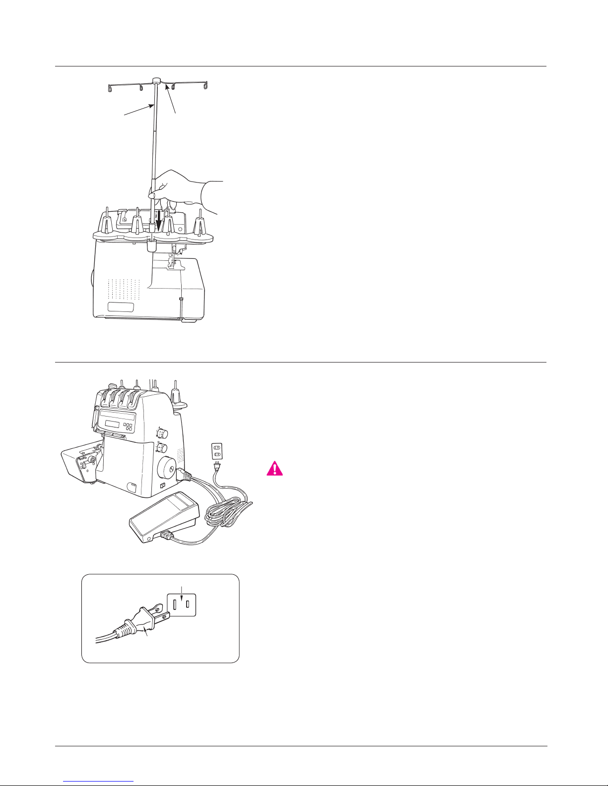
Thread stand
Push the support rod rmly into the socket on the back of the
machine.
Raise the support rod (A) fully, turning slightly until the position catches engage. Position the thread guide (B) on the
thread stand so that the arrow is to the front.
A
B
B
A
Attaching the foot control
Plug foot control into the machine socket (A) and then into
main socket (B). The foot control regulates the sewing speed.
The sewing speed can be adjusted by increasing or decreasing the pressure on the foot control.
“WARNING’’
This appliance has a polarized plug (one blade wider than the
other).
To reduce the risk of electric shock, this plug is intended to t
in a polarized main socket only one way.
If the plug does not t fully in the polarized main socket, reverse the plug. If it still does not t, contact a qualied electri-
cian to install the proper polarized main socket. Do not modify
the plug in any way. (for USA, Canada only)
Preparing the machine / Using the machine
Details of the machine
Polarized plug
(for USA, Canada only)
Polarized main socket
8
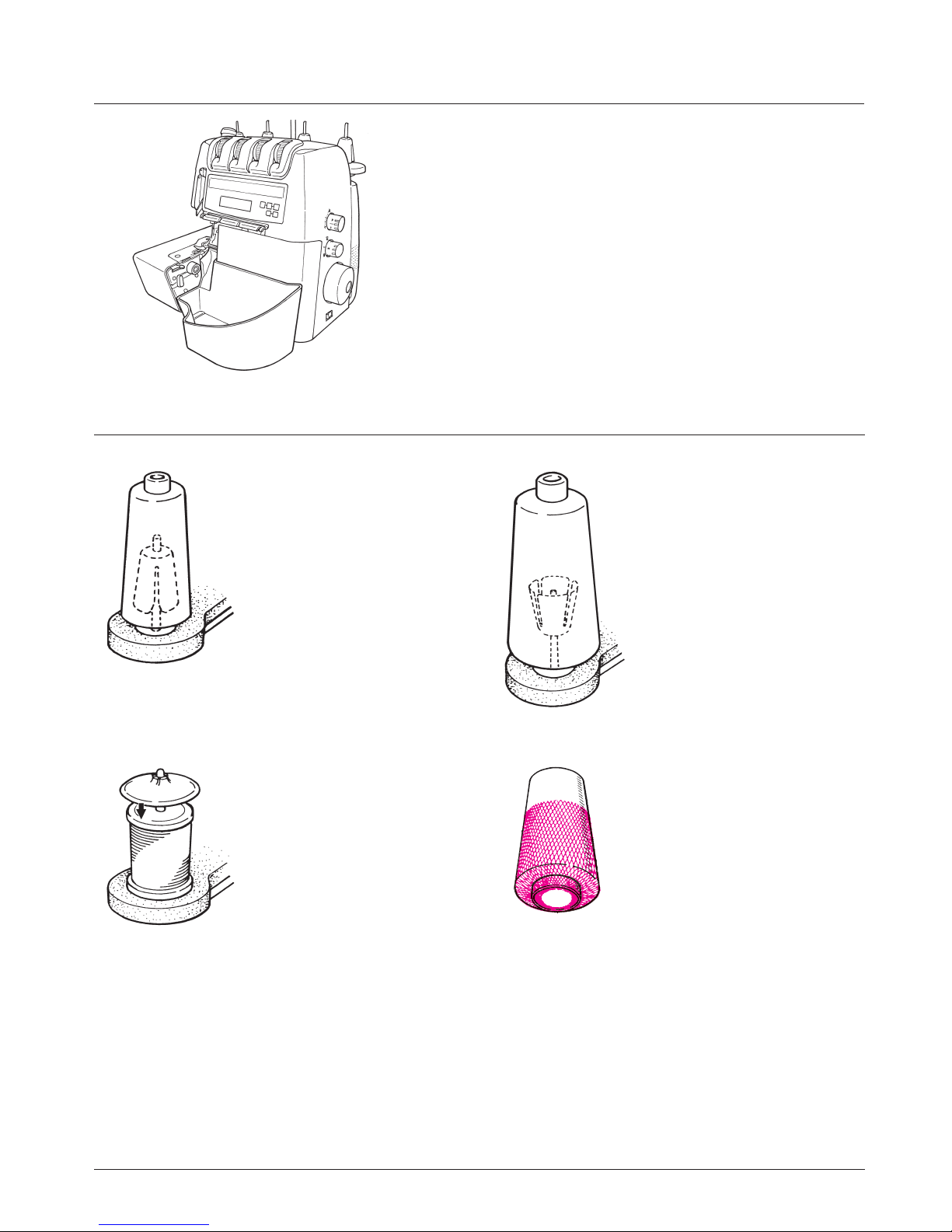
Waste collector
Clip the waste collector into the opening on the looper cover.
It catches the cut-off fabric as you sew, keeping your working
area neat and tidy.
Preparing the machine / Using the machine
Thread / cones /
spools
The anti-vibration cone
should be used with the
wider edge at the bottom on
the spool holder pin when
sewing with cones.
Large spools
If large industrial spools are
used, position the anti-vibration cone upside down on the
spool holder pin, i .e. with the
wider edge at the top.
Household spools
Remove the anti-vibration
cones. Place spools on
spool holder pins and push
the spool caps on with the
rounded side downwards.
Thread net
If the threads slip and get
twisted, cover the looper
spools with the net supplied in
the accessory bag.
9
Using the machine
Looper cover
To open, press to the right with your thumb in the indent
provided and tilt the cover towards you. To close push it
up and press lightly to the right. The cover engages automatically.
Safety device:
The sewing machine is equipped with a safety device in
order to prevent malfunction. In any of the following cases,
the safety device works to prevent the sewing machine
from running.
* When the looper cover is opened
* When the cloth plate is opened
* When the presser foot is raised
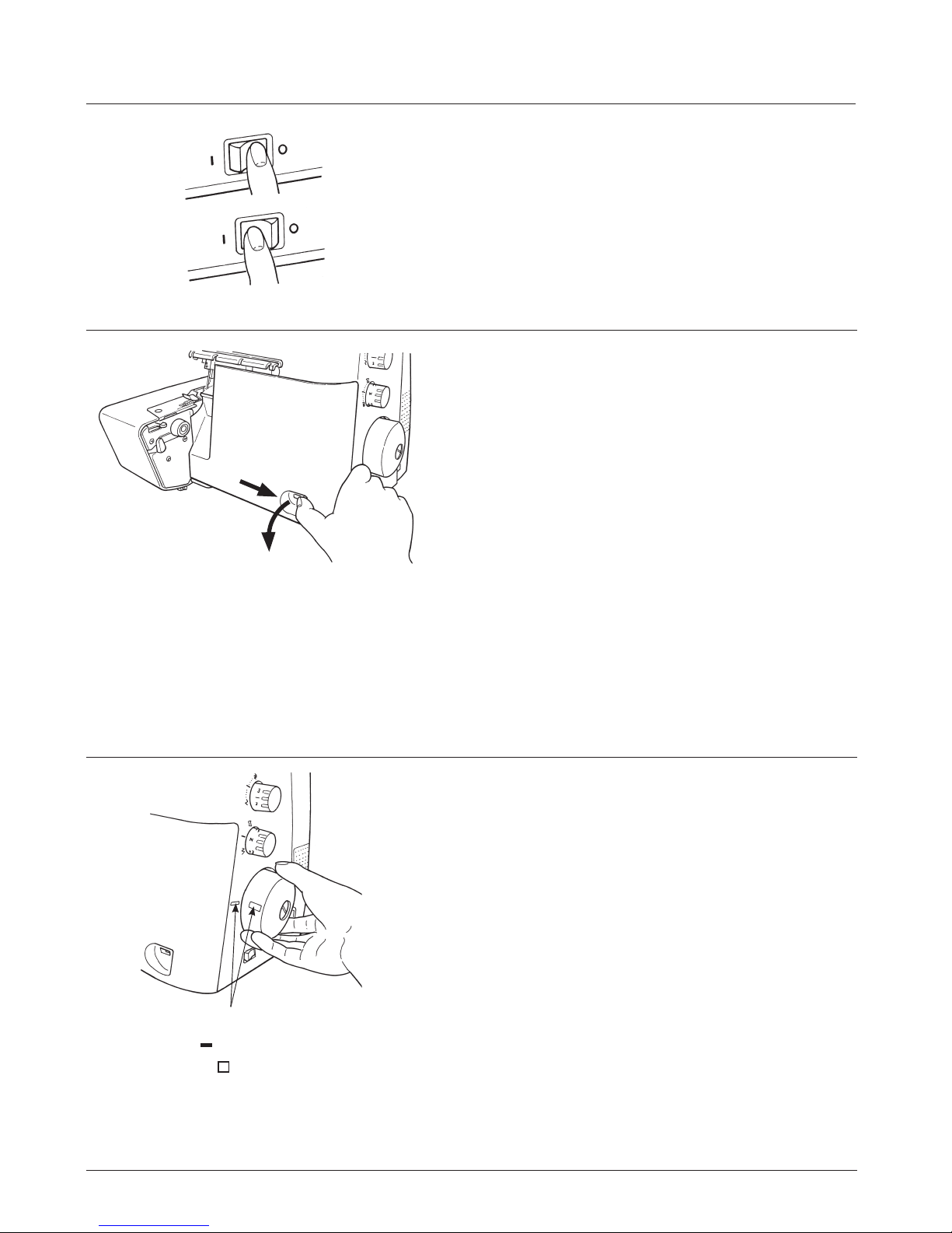
Main Power/light switch
The main power/light switch is conveniently placed on the
handwheel side of the machine in front of the socket.
0 = Off
I = On with light
Handwheel
The handwheel turns forward, i.e. in the same direction as
on a household sewing machine.
* The needle is brought to its upper end by
aligning the “
” marking on the side of the front
cover with the “
” marking on the handwheel.
10
Two step presser foot lifter with integrated front
foot lift
To raise the presser foot, lift the presser foot lever on the rear
of the machine, until it engages (A). It can be raised again to
the maximum height and held in this position to provide more
space between presser foot and stitch plate (B).
When the foot is raised (A and B), the front of the foot is automatically lifted.
Note:
When the presser foot is raised, all the tensions are released
making it easier to thread the machine.
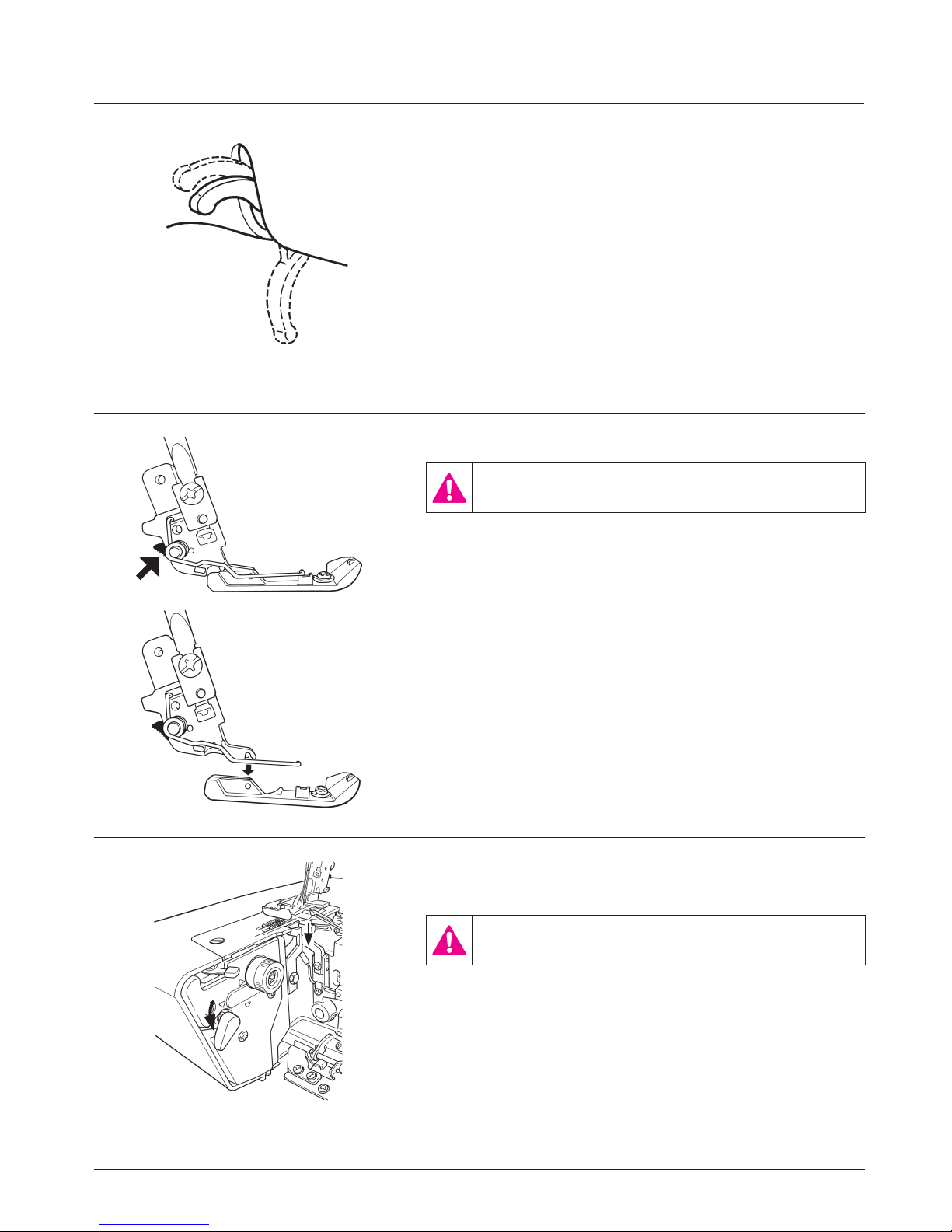
Changing the presser foot
Switch the machine off (power switch”0”) and deactivate the upper knife.
• Raise the presser foot.
• Turn handwheel towards you until needles are fully raised.
Match the matching up marks on handwheel and side cover.
Press the catch (C) to release the presser foot from the
clamp. Raise the presser foot shank to the highest position (B)
and remove the presser foot to the left. To attach the presser
foot, place it under the shaft. The groove in the shaft should
line up exactly with the presser foot pin (D). Lower the presser foot lifting lever and check that the groove in the shank
should line up exactly with the presser foot pin (D). If it is not
lined up, press the catch (C) to line up.
B
A
D
C
Using the machine
To carry out sewing without cutting the material
(the upper knife is deactivated)
Turn off the power switch before deactivating the
upper knife.
1. Lower the upper knife changeover knob in the direction of
the arrow.
2. Check to be sure that the knife is lowered.
Caution:
To activate the upper knife, bring the upper knife changeover
knob at position E. Turn the handwheel by two revolutions by
hand.
E
11
Using the machine
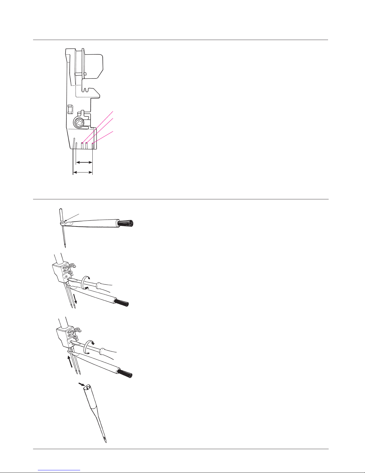
How to use the presser foot
Use the marker on the presser foot as a guide when placing
the material under the presser foot.
(F) Left needle position
(G) Right needle position
(H) Knife position (when the lower knife adjusting knob is set
at scale mark “1.5”)
The knife position represents the position at which the
material is cut.
8.5mm
10mm
F
G
H
Inserting the needles
Needles can be inserted quickly and easily with the practical
needle inserter (A).
Switch the machine off (Power switch to “0”)
Disconnect machine from electricity supply.
Turn handwheel towards you until needles are fully raised.
Match the matching up marks on handwheel and side cover.
Lower the presser foot.
Using the small screwdriver, loosen the needle setscrews and
remove the needles (B).
Place the right-hand needle, at side towards the back, into
the hole of the needle inserter and insert the needle as far as
possible into the needle clamp.
Tighten the setscrew lightly and then insert the left-hand needle in the same way and tighten both setscrews (C).
A
B
C

12
Needles
Needles must be in perfect condition.
Problems can occur if needles:
A are bent.
B are damaged or blunt.
C have hooked points.
Needle and thread
The needle size used depends on the thread. The needles should be in accordance with thread used.
When sewing, the thread is fed through the long groove in the needle. If the needle is too ne, the thread
does not t into the groove and stitches will be skipped.
Use needles No. 70 - 90.
* It is recommended to use JLx2 needle, especially when sewing thick materials, overlapped section, etc,
with overlock machine.
Thread/decorative threads
Sewing and special overlock threads are manufactured in a wide variety of types, weights and combination
of bres. It is worth investing in good quality threads for perfect sewing results. Decorative threads specially
made for overlockers (available on cones) are also becoming widely available. We recommend following the
basic guidelines when using special threads on your overlocker:
- Purchase threads on cones or spools which are produced exclusively for overlocking.
- When using normal spools, use the spool caps (in accessory bag).
- Only use decorative threads in the loopers. The thread must move easily and without resistance through
the thread guides and looper eyes.
- The thicker the thread, the longer the stitch length (3-4).
- The thicker the thread, the looser the tensions.
- Sew slowly when using decorative threads. Pull the thread chain gently to the rear when starting to sew.
Always test sew decorative threads before starting to sew your work.
Needle and thread
A
B
C
Thread, needle, application table
Thread Needles Where Application
All purpose overlock thread 120/2
(polyester)
70-90
Needles and looper
threads
For all overlock.
Polyester-continuous laments Loopers only Neatening edges
Woolly nylon Loopers only Soft seams in knits, rolled hems.
Spun Polyester 80-90
Needles and looper
threads
Seams in all fabrics.
Embroidery/darning and decorative
threads
70-90 Loopers only Neatening edges, rolled hems.

13
Adjustments and settings
Stitch length
It can be adjusted while sewing.
The stitch length is innitely variable from 1-4mm. Most overlock work is done with a basic setting of 2.5mm.
For roll hemming or narrow overlocking, it is best to set the
dial at “1 to 1.5”.
For blind stitch which requires the “use of separately-available
presser foot”, set the dial at “4”.
A
B
A
Cutting width
Switch the machine off (Power switch to “0”)
Disconnect machine from electricity supply.
• Raise the upper knife.
• Turn cutting width adjustment dial in the desired direction.
• Lower upper knife.
1 = 3–5 mm seam width
2 = 4–6 mm seam width
3 = 5–7 mm seam width
4 = 6–8 mm seam width
5 = 7–9 mm seam width
The position of the lower knife determines the width of the
seam.
Reduce the cutting width if the edges of fine fabric curl up
when being sewn (A).
Increase the cutting width if the loops seem to be too loose (B).
WARNING
Do not carry out sewing with a marking pin stuck in
the material. In addition, do not attempt to cut anything other than fabric and thread with the upper/
lower knives. Be aware that doing so can cause nee-
dle break or personal injury.

14
Adjustments and settings
D
C
2
1.5
N(1)
0.7
E
F
Differential feed
There are two feed dogs one front (C) and one rear (D). The
two feed dogs move independently and the distance each
feed dog travels during one complete movement can be
adjusted. The differential feed prevents fluting or waving in
knitted or stretch fabrics and movements between the layers
of fabric. It also ensures pucker-free seams in smooth fabric
such as nylon or closely woven fabric.
Perfectly at seams in knits or stretch fabrics.
The distance travelled by the front feed dog should be greater
than that of the rear feed dog. The front feed dog, therefore,
feeds an amount of fabric which the rear feed dog can take
up behind the needle without stretching the fabric. (E)
Pucker - free seams in nylon or closely woven
fabrics.
The distance travelled by the rear feed dog should be greater
than that of the front feed dog. The front feed dog, therefore,
holds the fabric back so that the rear feed dog can take it up
behind the needle without any puckering. (F)
Adjusting the differential feed
The differential feed can be adjusted by simply turning the differential feed adjustment dial in the direction desired. Always
make a trial run. The differential feed is innitely variable and
can be adjusted while sewing.
Adjusting the differential feed
Simply turn the dial in the direction desired for fully variable
adjustment while sewing. Test sew.
Effect Fabric
2
Wave-free seams
(G)
Thick wool knits, hand knitted
articles, very stretchy fabrics
1.5
Wave-free seams
(H)
Cotton, silk, synthetic jersey,
sweatshirt fabrics and ne knits
N Normal feed (I) Woven fabrics
0.7 No puckering (J)
Fine nylon jersey, closely woven
fabrics, lining fabric satin, poplin
G H
JI

15
Gathering
Using the differential feed, a single layer of fabric can be
gathered before sewing it to the garment.
For example, sleeve heads and lower edges, yokes, lace
edging or frills.
Adjustment:
• Stitch: 4-thread overlock
• Differential feed: 2
• Stitch length: 3-4
• Cutting width: 2-3
Increase the needle thread tension (6-8) for a tighter gather.
Adjustments and settings
Roll hemming
• Turn the handwheel towards you until the needles are fully
raised.
• For roll hemming, pull the overlocking width changeover
knob toward you and check that the overlocking claw retracts. (C).
• For overlocking, push the overlocking width changeover
knob away from you to check that the overlocking claw projects. (D).
The roll hemmer is fully integrated in the machine. The edge
of the fabric will be automatically rolled over, producing a very
narrow, ne seam or hem.
Roll hemming is ideal for nishing edges on all ne fabrics,
such as evening clothes, lingerie, scarves, frills and also for
curtains and napkins.
D
C
Presser foot pressure
The presser foot pressure is factory adjusted to a medium
setting.
Align the marker line on the presser foot pressure regulating
knob with the upper end of the top cover.
Position of knob for normal pressure
(M) = Medium.
More pressure: for thick or stiff fabrics such as denim, tweed,
rm linen (H) = High.
Less pressure: for light-weight or sheer fabrics and knits (L) =
Low.
M
H
L

16
Threading preparations / Tips
1. Extend the retractable support rod tted with open
thread guide as far as it goes.
2. Raise the presser foot. (Tension disk opens.)
3. Open the looper cover.
4. Turn the power on.
Threading sequence
The thread guides can be threaded in any sequence.
The threading sections are color coded correspondingly.
Threading the thread guide No. 1
Bring down the thread which is put on the retractable support
rod to thread the thread guide No. 1 from its left side. Then,
route the thread downward to bring it toward you.
Lower looper thread (red markings)
Upper looper thread (purple markings)
Right needle thread (green markings)
Left needle thread (beige markings)

17
Lower looper thread, red markings
Place the spool on the spool holder pin as illustrated.
(1) Raise the threading changeover lever in the di-
rection of the arrow.
Turn the handwheel toward you until it clicks.
(2) Thread the thread guide which is located just
above the spool from back to front.
(3) Thread the thread guide No. 1.
(4) Pull the thread by both hands and thread the
thread guide.
(5) Thread the thread guide.
(6) Pull out the thread by 20 to 30 cm to let it sag
inside the looper cover.
(7) Pass the top end of thread through threading
hole by 1 to 2 cm.
(8) Press the air-control pushbutton.
(9) Check to be sure that the thread comes out from
the top end of the lower looper.
(10) Bring the pulled-out thread down from above
the upper looper to route it under the presser
foot and pull it out from its rear.
Note:
If the upper or lower looper thread breaks during
sewing, re-threading is necessary.
Remove both the broken and unbroken looper
threads. Then, set the threading lever to the threading side to carry out threading of the upper and lower
loopers.
1
2
3
4
5
1
6
7
8
20-30cm
9
10
Threading 4/3 Thread OL

18
Upper looper thread, purple markings
Place the spool on the spool holder pin as illustrated.
(1) Raise the threading changeover lever in the di-
rection of the arrow.
Turn the handwheel toward you until it clicks.
(2) Thread the thread guide which is located just
above the spool from back to front.
(3) Thread the thread guide No. 1.
(4) Pull the thread by both hands and thread the
thread guide.
(5) Thread the thread guide.
(6) Pull out the thread by 20 to 30 cm to let it sag
inside the looper cover.
(7) Pass the top end of thread through threading
hole by 1 to 2 cm.
(8) Press the air-control pushbutton.
(9) Check to be sure that the thread comes out from
the top end of the upper looper.
(10) Pull the thread by approximately 10 cm to route
it under the presser foot and pull it out from its
rear.
Threading 4/3 Thread OL
1
1
2
4
5
6
7
8
9
20-30cm
3
10

19
Right-hand needle, green markings
Switch the machine off (power switch”0”)
Place the spool on the spool holder pin as illustrated.
(1) Thread the thread guide which is located just
above the spool from back to front.
(2) Thread the thread guide No.1.
(3) Route the thread in the groove.
(4) Put the thread under the thread guide plate.
(5) Thread the thread take-up cover (marked in
green)
(6) Thread the thread guide (right-hand side).
(7) Thread the needle bar thread guide (right-hand
side).
(8) Turn the handwheel to align the “
” marking on
it with the “
” marking on the side of the front
cover.
(9) Set the right-/left-needle changeover lever to the
right needle side.
Be sure to move the right-/left-needle change-
over lever to the right needle side until it will go
no further.
(10) Lower the threading lever as far as it goes.
(11) Push the thread into section A with both hands.
(12) The thread automatically passes through the
needle eyelet by pushing the threading lever
upward.
(13) Pull out the thread by approximately 10 cm to
route it under the presser foot and draw it out
from its rear.
Threading 4/3 Thread OL
1
3
4
5
7
7
6
6
12
13
9
8
2
10
11
A

20
Left-hand needle, beige markings
Switch the machine off (power switch”0”)
Place the spool on the spool holder pin as illustrated.
(1) Thread the thread guide which is located just
above the spool from back to front.
(2) Thread the thread guide No.1
(3) Route the thread in the groove.
(4) Put the thread under the thread guide plate.
(5) Thread the thread take-up cover (marked in
beige)
(6) Thread the thread guide (left-hand side).
(7) Thread the needle bar thread guide (left-hand
side).
(8) Turn the handwheel to align the “
” marking on
it with the “
” marking on the side of the front
cover.
(9) Set the right-/left-needle changeover lever to the
left needle side.
Be sure to move the right-/left-needle change-
over lever to the left needle side until it will go no
further.
(10) Lower the threading lever as far as it goes.
(11) Push the thread into section A with both hands.
(12) The thread automatically passes through the
needle eyelet by pushing the threading lever
upward.
(13) Pull out the thread by approximately 10 cm to
route it under the presser foot and draw it out
from its rear.
Threading 4/3 Thread OL
1
3
4
5
7
7
6
6
12
13
9
8
2
10
11
A

21
Threading 4/3 Thread OL
Looper threader
How to use the looper threader
To thread woolly thread or any thread that cannot
pass smoothly through the threading holes, it is
recommended either to use the “looper threader”
supplied in the accessory bag, or to prepare an approximately 30 cm long spun thread or the like, tie it
at the end of the woolly thread, pass the spun thread
through the threading hole and pull it until the woolly
thread passes through the hole.
(The looper threader can also be used as a cleaning
tool for pipes.)
1. Raise the threading changeover lever in the direction of the arrow.
Turn the handwheel toward you until it clicks.
2. Pass the thread through the looper threader ring.
3. Pass the looper threader through the looper by
hand until it comes out from the end of the looper.
Caution:
Do not press the air-control pushbutton.
Note:
If the upper or lower looper thread breaks during
sewing, re-threading is necessary. Remove both
the broken and unbroken looper threads. Then, set
the threading lever to the threading side to carry out
threading of the upper and lower loopers.
Caution:
After the completion of threading of the upper and
lower loopers, return the threading lever to its home
position. If not, the looper cover cannot be closed.

22
Sewing test
Use two plies of material to check that the quality of the nished seam and thread tensions are correct.
1. Close the looper cover. Turn the power on.
2. Check that the upper knife is raised.
3. Lower the presser foot.
4. While holding the thread trailing from the rear of the presser foot by hand, depress the controller to produce chain-off
thread by 6 to 7 cm.
5. Raise the front side of the presser foot with fingers and
insert the material under the presser foot until the upper
knife is reached.
6. Start the sewing machine.
7. After the completion of sewing, produce chain-off thread
by 5 to 6 cm.
8. Put the chain-off thread over the thread trimming blade for
trimming.
* Chain-off thread is stitch-formed thread with no material.
5-6 cm
Trial sewing

23
Check your trial run 4/3 Thread OL
1. Upper looper thread (purple).
2. Lower looper thread (red).
3. Right-hand needle thread (green).
4. Left-hand needle thread (beige).
Perfect stitch formation is when both looper threads meet at
the fabric edge. The needle threads form straight stitches for
a stretchy and durable seam.
Thread tension
Thread tension should be properly adjusted to suit the various
types of work.
The ideal tension setting for most fabrics and threads is be-
tween 3 and 5. However this can vary quite considerably when
special threads such as lament, woolly nylon, buttonhole twist
(cordonnet), pearl yarn or decorative threads are used. Only
use decorative threads in the looper. The thread must move
easily and without resistance through the looper eye.
Innitely variable adjustments can be made from 1 - 9.
Turn the dial downwards for less tension.
Turn the dial upwards for more tension.
1
2
4
3
4
3
Thread tension
Adjusting the thread tension
Turn the tension dials by quater or half number, then test sew
again and check the result.
• The loops are formed on the underside.
Tighten the upper looper thread tension, (purple) or loosen
the lower looper thread tension, red (A).
• The loops are formed on the upper side.
Tighten the lower looper thread tension, (red) or loosen the
upper looper thread tension, purple (B).
• The right-hand needle thread forms loops on the underside.
Tighten the right-hand needle thread tension, green (C).
• The left-hand needle thread forms loops on the underside.
Tighten the left-hand needle thread tension, beige (D).
• The edge of the fabric curls up, tension of both looper
threads is too tight:
Loosen upper and lower looper thread tensions, purple and
red (E).
• The fabric puckers during sewing:
Loosen the right- or left-hand needle thread tension, green
or beige (F).
A
注意
A
A
注意
B
A
注意
C
A
注意
D
A
注意
E
A
注意
F

24
Sewing in tape
The standard presser foot is equipped with a tape
guide. A tape can be sewn into the shoulder or side
seams of garments made from knits or stretch fabrics to prevent stretching.
• Turn handwheel towards you until needles are fully
raised. Match the matching up marks on handwheel and side cover.
• Raise the presser foot.
• Lay the tape under the presser foot and slide it
carefully into the tape slot.
• Lower the presser foot.
• Sew a few stitches on the tape.
• Loosen the setscrew (A) and adjust the tape guide
to suit the width of the tape (B).
• Re-tighten setscrew.
• Raise the tip of the presser foot and place work
underneath. Sew.
B
A
Practical Sewing - Overlock
Carrying out hemming and narrow over-
locking
The sewing machine incorporates the hemming device to enable roll hemming and narrow overlocking.
The sewing machine is able to overlock the material
edges such as bottoms and sleeve cuffs beautifully
while automatically folding them inwardly.
Preparation for hemming
1. Install the right needle only.
2. Pull the overlocking width changeover knob to-
ward you to lower the overlocking claw.
3. Set the lower knife adjusting knob at the scale
mark “1 to 1.5”.
4. When using filament thread or woolly nylon
thread, set the stitch length adjustment dial (stitch
length) at “1 to 1.5”.
Roll hemming (A)
The roll hemming is the stitch system that laps the
material edge with the upper looper thread.
Narrow overlocking (B)
The narrow overlocking is the overlock stitch system
overlocking width of which is narrower than the standard one.
2
3
4
1
4
1
4
A
B
1
1

25
Practical Sewing - Overlock
2-/3-thread changeover attachment
Use the 2-/3-thread changeover attachment when it is desired
to carry out 2-needle overlocking, cover stitch (flatlock) or
2-thread hemming.
1. Turn off the power switch.
2. Press the 2-/3-thread changeover attachment mounted on
the upper looper to the left.
3. Check that the projection of the 2-/3-thread changeover
attachment is inserted into the hole in the top end of the
looper.
In the aforementioned state, the upper looper thread is not
fed. However, the lower looper thread is fed to form 2-thread
stitches.
Wrapped overlocking with three threads
For wrapped overlocking with the right needle (3
to 7 mm in width)
1. Remove the left needle.
2. Thread the upper and lower loopers in the same manner
as the standard sewing (2-needle, 4-thread).
For wrapped overlocking with the left needle (5
to 9 mm in width)
1. Remove the right needle.
2. Thread the upper and lower loopers in the same manner
as the standard sewing (2-needle, 4-thread).

26
Cover stitch with three threads (atlock)
1. Deactivate the upper knife.
2. Use a decorative thread as the upper looper thread. (Filament thread is best-suited as the needle thread and the
lower looper thread. However, spun thread can also be
used.)
3. Adjust the tension regulating dial and stitch length adjustment dial. Adjust the dials so that the thread tension is
slightly reduced.
Scale mark
of tension
regulating
dial
Thread tension of left or right
needle
1 - 3
Thread tension of upper looper 1 - 5
Thread tension of lower looper 5 - 7
Stitch length adjustment dial 2 - 2.5
4. Use either the left needle or the right needle only.
In the case of the left needle: Wide cover stitches are
sewn. (5 to 9 mm)
In the case of the right needle: Narrow cover stitches are
sewn. (3 to 7 mm)
5. Fold the material in two. Carry out sewing with a preset
overlocking width.
6. After the completion of sewing, unfold the material.
1
2
3
4
5
1
1
1
2
3
4
4
5
3
3
Thread breakage during sewing
Sew off immediately at an angle and remove the work. Rethread.
If the upper or lower looper thread breaks during sewing,
re-threading is necessary. Remove both the broken and unbroken looper threads. Then, set the threading lever to the
threading side to carry out threading of the upper and lower
loopers.
First thread the looper and then the needles.
Start sewing again about 2 - 3 cm in front of the break.
Unpicking seams
Using sharp scissors, cut the loops (C).
Pull the needle thread (D) and the stitches will come undone.
2-3 cm
C
D
C
D
Thread breakage during sewing
Sew off immediately at an angle and remove the work. Re-thread.
If the lower looper thread has broken, cut off both needle threads at the needles and
remove surplus thread from below.
First thread the looper and then the needles.
Start sewing again about 2 - 3 cm in front of the break.
Draadbreuk tijdens het naaien
Naai direct in een hoek van de stofkant af en verwijder uw werkstuk. Rijg de machine
opnieuw in. Als de ondergrijper draad is gebroken, knip dan de draden af bij de naalden
en verwijder de overblijfselen van onder af. Rijg eerst de grijper in en dan de naalden.
Begin opnieuw te naaien op circa 2-3 cm voor de plek waar de draadbreuk ontstond.
Fadenreissen während des Nähens
Sofort im Winkel von der Soffkante wegnähen, Nähgut entfernen. Neu einfädeln. Ist der
untere Greiferfaden gerissen, beide Nadelfäden beim Nadelöhr abschneiden und
entfernen. Zuerst den Greifer einfädeln, anschliessend die Nadeln. Ca. 2-3cm vor der
Fadenriss-Stelle erneut mit Nähen beginnen.
Cassure du fil durant la couture
Atteindre aussitôt le bord du tissu en réalisant un angle aigu. Puis retirer l’ouvrage.
Recommencer l’enfilage. Si c’est le fil du boucleur inférieur qui est cassé, il faut alors
couper les deux fils d’aiguilles au niveau du chas, et les enlever. Enfiler d’abord le
boucleur, ensuite les fils d’aiguilles. Reprendre la couture environ 2 à 3 cm avant l’endroit
où a eu lieu la cassure.
Unpicking seams
Using sharp scissors, cut the loops (C).
Pull the needle thread (D) and the stitches
will come undone.
Zoom uithalen
Met een scherpe spitse schaar de
lussen knippen ( C). Trek aan de naald
draden en het stiksel komt los.
Stiche auftrennen:
Mit einer spitzen Schere die Schlingen
zerschneiden (C). An den Nadelfäden
ziehen (D), der Stich löst sich auf.
Découdre une couture
Avec un ciseau pointu, couper les boucles
(C). Tirer sur les fils d’aiguilles (D). Ainsi, la
couture se libère.
C
D
C
D
2-3 cm
缝纫中断线、缝口合拢
马上停止缝纫,取出面料。重新穿线。
如果下弯针断线,则需要剪断左、右机针线,并从下面拉掉余线。
先穿弯针线,再穿机针线。
在离接口处2-3cm重新开始缝纫。
缝口的拆法
用锋利的剪刀剪断线圈(C), 拉机
针线(D), 针脚就被拆开。
2-3 cm
2-3 cm
Practical Sewing - Overlock

27
Practical Sewing - Overlock
4
1
Securing thread ends at the beginning and end
of sewing
Overlock stitches can unravel if the threads are not secured
at the beginning and end of sewing. Secure the thread ends.
Securing thread ends with the overlock machine
1)
Securing thread ends at the beginning of sewing
1. Pull out chain-off thread produced at the beginning of sewing by 3 to 4 cm.
2. Sew the material by two or three stitches.
3. Lower the needle and raise the presser foot.
4. Stretch the chain-off thread to put it between the presser
foot and the material from the left side.
5. Lower the presser foot and sew the chain-off thread on the
material.
* If you do not sew the chain-off thread on the material, pro-
duce a longer chainoff thread at the beginning and end of
sewing. Then, make a knot of the chainoff thread or put the
chain-off thread under the seam with a wool needle.
* When stitches cross each other, chain-off thread is auto-
matically secured.
6
4
2
3
2) Securing thread ends at the end of sewing
1. Stop the needle at the end of material.
2. Lift the needle.
3. Raise the presser foot.
4. Turn the material upside down. Lower the needle so that it
enters the outside edge of nished seam.
5. Lower the presser foot.
6. Carry out sewing to produce chain-off thread by 2 to 3 cm
taking care not to allow the nished seam to come in contact with the upper knife. Remove the material.
7. Secure the chain-off thread.

28
Practical Sewing - Overlock
A
In the case of securing thread ends with a wool needle: (A)
Leave a 2 to 3 cm long chain-off thread at the beginning and end of sewing.
Put the chain-off threads in the nished seam by means of a wool needle.
B
In the case of securing thread ends with glue for handicraft: (B)
Apply a little amount of glue for handicraft at the root of chain-off thread on the
material. Cut out the excess of chain-off thread after the glue has dried.
C
Securing thread ends by making a knot: (C)
Bind all threads together and make a knot at the nearest position of the material. Then, cut out the excess of the threads.

29
Set values of 15 different kinds of stitch can be visually checked on the LCD screen.
In addition, three different set values can be added to the current set value.
(Memory number)
LCD indication
No. Operation Display Remarks
1 When the power
is turned ON
“Welcome” display
You can select language from 9
languages. Refer to page 32. (Default
setting is English.)
2 4 seconds later Sewing type name display screen
Set value display screen
The screen which was displayed at
the last time when the power was
turned OFF.
3
When
is
pressed
Sewing type name display screen
Set value display screen
The screen is changed over between
the sewing type name display screen
and the set value display screen.
4
When
or
is pressed
Sewing type name display screen
Set value display screen
Select the stitch type.
Select the set value.
Memory No.
Upper knife
Upper knife release
2/3 thread changeover attachment
Roll hem selection lever
Differential feed
Stitch length
Cutting width
Needle position
Left needle thread tension
Right needle thread tension
Upper looper thread tension
Lower looper thread tension
Stitch No.
LCD indication button
Edit button
Conrmation button
Default button
1. Basic method of use
Roll hem selection
lever
Press the lever away
from you to let the
roll hemming claw
come out.
Pull the lever toward
you to lower the roll
hemming claw.
2/3thread changeover
attachment
To release the
attachment
To set the attachment

30
No. Operation Display Remarks
1
When
is pressed
Initial value display screen
The initial value of the selected stitch type is displayed.
The initial value is displayed as long as
is held
pressed.
2. How to display the initial value
No. Operation Display Remarks
1
When
is pressed
Edit item selection screen
Display of selected item ashes on and off.
2
When
or is
pressed
Edit item selection screen
Select the item you want to edit.
3
When
is pressed
Edit screen
4-a
When
or is
pressed
Edit screen
The value is set.
4-b
When
is pressed
Edit screen
The value returns to the initial value.
5
When
is pressed
Edit item selection screen
The value is stored in memory and the screen returns
to the edit item selection screen.
If the value differs from the initial value, the relevant
item is highlighted.
6
When
is pressed
Sewing type name display screen
Set value display screen
The screen returns to the previous screen.
3. How to edit the set value
* The initial value is the default value which has been fac-
tory-set at the time of shipment.

31
No. Operation Display Remarks
1 Sewing type name display screen
Set value display screen
Edit item selection screen
Display the stitch pattern you want to initialize.
2
Press
while keep-
ing
held pressed.
I
nitialization check screen
3 When one of them is
pressed:
: Initialize
: Cancel
Sewing type name display screen
Set value display screen
Edit item selection screen
The set value is initialized and the screen returns to
the previous screen.
4. How to initialize the set value

32
No. Operation Display Remarks
1 Sewing type name display screen
Set value display screen
Display the stitch pattern you want to add or delete.
2
Keep
held pressed
for two seconds.
Memory check screen
Caution:
If there are already three or more memory numbers,
no more one can be added.
In the case the stitch pattern selected is not a memory number, it can not be deleted.
3 When one of the follow-
ing is pressed:
: Add
: Delete
: Cancel
Sewing type name display screen
Set value display screen
Addition or deletion of the memory number is
executed and the screen returns to the previous
screen.
5. How to use the memory number
The memory number is the function for increasing the number of set value display screens.
For each of 15 stitch patterns, three memory numbers can be added to the current set value at the maximum.
Example)
The current set value of “Stitch
pattern 1” can be changed to
three different set values.
First
Second
Third
The current set value of “Stitch
pattern 2” can be changed to
three different set values.
First
Second
Third
No. Operation Display Remarks
1 When the power is turned
ON while keeping
and
held pressed
Language selection screen
The currently-selected language is displayed.
2
When
or is
pressed
Language selection screen
Select the language.
3
When
is pressed
LCD contrast adjustment screen
4-a
When or is
pressed
LCD contrast adjustment screen
Set the contrast.
4-b
When is pressed
LCD contrast adjustment screen
The contrast returns to the initial value.
5
When is pressed
“Welcome” display
6. How to set the language and the LCD contrast

33
Stitch
No.
Stitch
Needle
position
Thread tension
Cut-
ting
width
Stitch
length
Differ-
ential
feed
Roll
hem se-
lection
lever
2/3
thread
change-
over at-
tachment
Upper
knife
Left
nee-
dle
Right
nee-
dle
Upper
looper
Lower
looper
1
4-Thread overlock with
integrated safety seam
4.0 4.0 4.0 4.0 1-5 2.5 N
2
3-Thread super stretch
4.0 4.0 --- 2.5 1-5 2.5 N
3
3-Thread overlock
(left needle)
- 4.0 --- 4.0 4.0 1-5 2.5 N
4
3-Thread overlock
(right needle)
- --- 4.0 4.0 4.0 1-5 2.5 N
5
3-Thread Flatlock
(left needle)
- 1.0 --- 3.0 6.0 --- 2.5 N
6
3-Thread Flatlock
(right needle)
- --- 1.0 3.5 6.0 --- 2.5 N
7
3-Thread narrow seam
- --- 4.5 4.0 5.0 1.0 1.0 N
8
3-Thread roll hem
- --- 4.0 3.5 6.0 1.0 1.0 N
9
2-Thread wrapped
overlock (left needle)
- 5.0 --- --- 3.5 1-5 2.5 N
10
2-Thread wrapped
overlock (right needle)
- --- 4.5 --- 3.0 1-5 2.5 N
11
2-Thread Flatlock
(left needle)
- 2.0 --- --- 4.0 --- 2.5 N
12
2-Thread Flatlock
(right needle)
- --- 3.0 --- 5.5 --- 2.5 N
13
2-Thread roll hem
- --- 4.0 --- 5.0 1.0 1.0 N
14
2-Thread overlock
(left needle)
- 2.0 --- --- 5.0 1-5 2.5 N
15
2-Thread overlock
(right needle)
- --- 2.5 --- 6.5 1-5 2.5 N
4-Thread / 3-Thread2-Thread
* The scale marks of the tension regulating dial listed below are just a guide. The correct adjustment differs
according to the type of thread and material to be used.
Stitch chart

34
Precautions to be taken when handling oil
* In the event the oil gets in the eye or adheres on skin, immediately wash it off in order to prevent irrita-
tion and rash.
* If swallowed accidentally, immediately seek for medical advice in order to prevent diarrhea and vomiting.
* Keep the oil away from children.
* Oil disposal is obliged by legislation. Dispose of the oil properly in compliance with the relevant legisla-
tion.
Cleaning and lubricating
Turn off the power switch and disconnect the power plug from the wall outlet before starting cleaning
or lubricating the machine.
As you use the sewing machine, lint is likely to accumulate
in the sewing machine. It is necessary to remove the lint pe-
riodically. Since lint accumulates particularly in the sections
around the throat plate and lower knife, remove the lint from
those sections on a periodical basis. (A)
When cleaning the pipes of the upper and lower loopers, use
the “looper threader” supplied in the accessory bag. (Refer to
page 21 for how to use it.)
The sewing machine uses special materials for important
parts. Apply one or two drops of machine oil to the sections
illustrated.
To carry out cleaning with the cloth plate opened
Be sure to turn off the power switch before opening
the cloth plate.
• How to open the cloth plate
Push this side of the cloth plate to the left to open it.
• How to close the cloth plate
Push the cloth plate toward the sewing machine.
A
Maintenance
Replacing the knife
It is not normally necessary to replace the lower knife since it is made of special ultrahard material. If the
knife blade tip has chipped, replace the knife with a new one.
Contact your distributor for the replacement of the lower and upper knives.

35
Problem Cause Solution Page
The machine
does not sew:
• Looper or cloth plate cover is open.
• The main switch is not on.
• The machine is not plugged in.
• Close the looper or the cloth plate
cover.
• Switch machine on. (Main switch to “I”)
• Insert plug into main socket.
9
9
7
Fabric does
not feed
evenly
• Differential feed is wrongly adjusted.
• Presser foot pressure is too low.
• Check the differential feed setting.
• Adjust the presser foot pressure.
14
15
Thread
breaks
• Thread tension is too tight for the
thread being used.
• The machine is not threaded correctly.
• Needles are incorrectly inserted.
• Wrong needles.
• Reduce thread tension.
• Check the threading.
• Insert needles fully into needle clamp
with at side to the back.
• Use needle system 130/705H or JLx2.
23
17
11
11
Needles
break
• Needles are bent or blunt, points are
damaged.
• Needles are not inserted correctly.
• Fabric was pulled while sewing.
• Replace needles.
• Insert needles fully into needle clamp
with at side to the back.
• Guide fabric gently with both hands.
12
11
--
Skipped
stitches
• Needles are bent or blunt.
• Wrong needles used.
• Presser foot pressure is too low.
• Replace the needles.
• Use needle system 130/705H or JLx2.
• Increase presser foot pressure.
11
11
15
Poor stitch
formation
• Threads are not correctly between the
tension dials.
• Thread has got caught.
• Machine is incorrectly threaded.
• Check if thread is lying between tension discs.
• Raise the presser foot and pull the
thread.
• Check threading path of each thread.
• Check threading path of each thread.
16
16
17
17
Seams ute
or wave, especially when
sewing knits
• Fabric was pulled while sewing.
• Presser foot pressure is too tight.
• Differential feed is set incorrectly.
• Guide fabric gently.
• Reduce presser foot pressure.
• Adjust differential feed to N - 2.
-15
14
Seams puck-er• Needle thread tension is too tight.
• Differential feed is set incorrectly.
• Reduce the needle thread tension.
• Adjust differential feed to 0.7 - N.
23
14
Fabric edges
curl
• Too much fabric is in the stitch.
• Thread tension is too tight.
• Stitch selection lever is on roll hem.
• Reduce cutting width.
• Reduce thread tension.
• Set selection lever to overlock.
13
23
15
Trouble shooting guide

36
Problem Cause Solution Page
Thread loops
are too loose
• Too little fabric in the stitch. • Increase the cutting width. 13
Motor failure • Noise is heard.
• Motor does not turn at all.
• Sparks are abnormally large.
• Replace the carbon brush with a new
one.
(Note) Contact your distributor to ask
for the replacement of the carbon brush.
--
Needle eyelet
cannot be
threaded
• The “
” marking on the side of the
front cover is not aligned with the “
”
marking on the handwheel.
• Turn the handwheel to align the “
”
marking on it with the “
” marking on
the side of the front cover.
19,20
Upper and
lower loopers
cannot be
threaded
• When the handwheel is not xed.
• When the thread is not inserted into
the bottom of the threading hole.
• When the thread is not slacked before
the threading hole.
• When the thread is caught somewhere
in the thread path.
• When the pipe is clogged with lint.
• Raise the threading changeover lever
and turn the handwheel to x it.
• Insert the thread into the threading
hole by 1 to 2 cm.
• Slack the thread before the threading
hole.
• Remove the thread from the location
where it has been caught.
• Thread the loopers by means of the
looper threader supplied in the accessory bag to remove the lint in the pipe.
17,18
17,18
17,18
--
21

37
Stitch choice Over lock 2 needles, 2 loopers: 4 thread overlock with integrated safety seam
1 needle, 2 loopers: 3 thread overlock, atlock roll hem
1 needle, 1 looper: 2 thread overlock, atlock roll hem
2 needles, 1 looper: 3 thread super stretch
Needle system SCHMETZ 130/705 H or JLx2
Seam width 5-7 mm (3/2 thread overlock)
7-9 mm (4 thread overlock / 3/2 thread overlock / 3 thread super stretch)
Stitch length 1-4 mm
Differential feed No puckering 0.7 - N
No waving or uting in knits N - 2
Presser foot lifter 5 mm
Handwheel Rotates forwards
Sewing speed Up to 1,500 sti/min
Weight 9 kg
Dimensions 330 (W) × 280 (D) × 310 (H) mm
Foot control model No. YC-482 (USA and Canada only)
YC-483N (220-240V)
We reserve the right to make changes in the interest of technical progress.
Technical data

38
Contact your local dealer.
• Blind stitch presser
foot
• Beading presser foot
• Elasticator
• Gathering presser
foot
• Cording presser foot
• Piping presser foot
Optional Accessories

Copyright © 2015 JUKI CORPORATION
All rights reserved throughout the world.
2-11-1, TSURUMAKI, TAMA-SHI,
TOKYO, 206-8551, JAPAN
PHONE : (81)42-357-2341
FAX : (81)42-357-2379
00091540166594
 Loading...