

Page 1

LZ-2280A Series
INSTRUCTION MANUAL
Page 2

CONTENTS
1. SPECIFICATIONS ......................................................................................................... 1
2. INSTALLATION
2-1. Installation of the sewing machine...............................................................................................4
2-2. Attaching the belt cover ................................................................................................................4
2-3. Inserting the needle ....................................................................................................................... 5
2-4. Installing the control panel ...........................................................................................................6
............................................................................................................. 4
3. PREPARATION OF THE SEWING MACHINE ............................................................. 6
3-1. Lubrication......................................................................................................................................6
3-2. Adjusting the amount of oil in the hook ......................................................................................7
3-3. Adjusting the amount of oil (oil splashes) ................................................................................... 8
3-4. Winding the bobbin thread ............................................................................................................9
3-5. Inserting the bobbin case and the bobbin ................................................................................. 10
3-6. Threading the machine head ...................................................................................................... 11
3-7. Adjusting the pedal ...................................................................................................................... 11
4. ADJUSTING THE SEWING MACHINE ......................................................................12
4-1. Adjusting the thread tension ......................................................................................................12
4-2. Adjusting the zigzag width ..........................................................................................................13
4-3. Adjusting the pressure of the presser foot ...............................................................................14
4-4. Adjusting the height of the presser bar .....................................................................................14
4-5. Adjusting the micro-lifting mechanism of the presser foot .....................................................14
4-6. Adjusting the stitch length ..........................................................................................................15
4-7. Adjusting the denser stitching ...................................................................................................15
4-8. Height and inclination of the feed dog ....................................................................................... 16
4-9. Attaching/removing the hook .....................................................................................................16
4-10. Adjusting height of the needle bar .............................................................................................17
4-11. Adjusting the needle-to-hook timing and the needle guard ..................................................... 17
4-12. Adjusting the stop position of the needle..................................................................................18
4-13. Adjusting the thread trimmer ...................................................................................................... 19
4-14. Needle thread feeding device .....................................................................................................20
4-15. Position of the wiper .................................................................................................................... 20
5. OPERATION OF THE SEWING MACHINE ................................................................ 21
5-1. How to operate the pedal (In the case of the direct-drive type sewing machine) .................. 21
5-2. One-touch type reverse feed switch ..........................................................................................21
5-3. Changing over the needle-throwing method ............................................................................. 22
5-4. LED light .......................................................................................................................................22
6. OPTIONAL .................................................................................................................. 23
6-1. Pedal-operated reverse feed device (RF-1) ...............................................................................23
6-2. Joining foot for the lockstitch presser foot ............................................................................... 23
6-3. Auxiliary thread take-up kit .........................................................................................................23
7. MOTOR PULLEY AND BELT ..................................................................................... 24
8. TROUBLES AND CORRECTIVE MEASURES
.......................................................... 25
Page 3
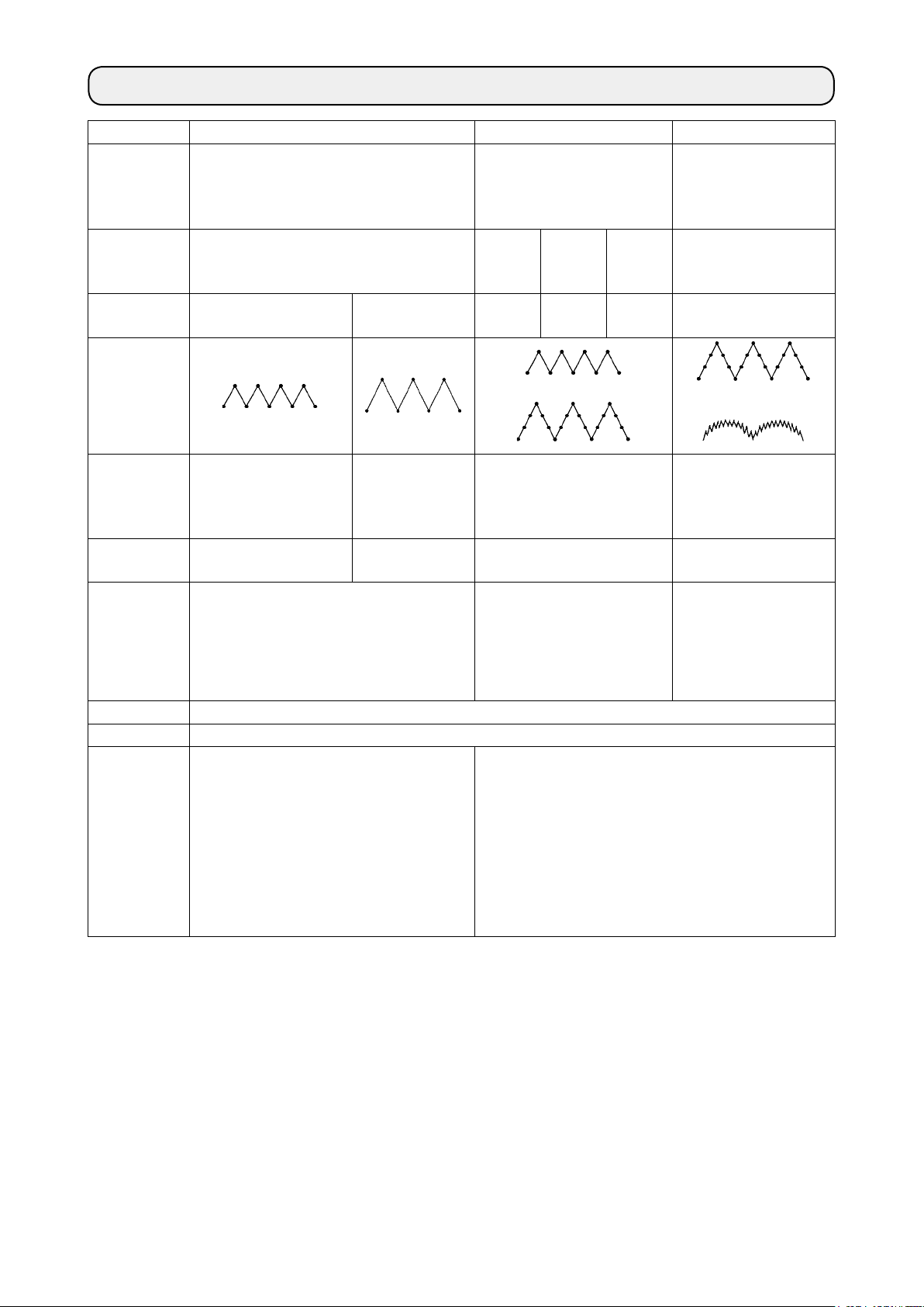
1. SPECIFICATIONS
Model LZ-2280A * LZ-2284A * LZ-2287A
Type of zigzag
Motor-drive
specication
Specication
[ * section]
Standard zigzag Selectable between standard
zigzag stitching and 3-step
zigzag stitching
V-belt V-belt/
Direct
drive
Direct
drive
V-belt/
Direct
drive
A (Narrow width) B (Wide width) - -7 T -
Selectable between
3-step zigzag stitching
and 24-stitch standard
scallop zigzag stitching
V-belt
Stitch diagram
Max. zigzag
width (mm)
Max. feed pitch
(mm)
5
[4 at the time of delivery]
2.5 (Normal/reverse feed)
[2 at the time of delivery]
8 3-step zigzag : 10
5 (Normal feed)
4 (Reverse feed)
[8 at the time of delivery]
Standard zigzag : 5
[5 at the time of delivery]
2.5 (Normal/reverse feed)
[2 at the time of delivery]
or
[8 at the time of delivery]
2.5 (Normal/reverse feed)
[2 at the time of delivery]
5,000 5,000
(3-step zigzag : Zigzag width
Max. sewing
speed (sti/min)
= less or 8 mm)
4,000
(3-step zigzag : Zigzag width
= more than 8 mm)
= more than 8 mm)
Needle SCHMETZ 438SUK (Nm75) : Nm65 to 90, DP x 134 (#10) : #9 to 14
Oil JUKI CORPORATION GENUINE OIL 7
Noise
Equivalent continuous emission sound
-
pressure level (LpA) at the workstation:
A-weighted value of 80 dB; (Includes K
= 2.5 dB); according to ISO 10821- C.6.2 -
ISO 11204 GR2 at 4,500 sti/min.
- Equivalent continuous emission sound pressure level
(LpA) at the workstation:
pA
A-weighted value of 80 dB; (Includes K
according to ISO 10821- C.6.2 - ISO 11204 GR2 at 4,400
sti/min.
- Sound power level (LWA);
A-weighted value of 84.6 dB; (Includes KWA = 2.5 dB);
according to ISO 10821- C.6.2 - ISO 3744 GR2 at 4,500
sti/min.
or
10
5,000
(Zigzag width
= less or 8 mm)
4,000
(Zigzag width
pA
= 2.5 dB);
– 1 –
Page 4
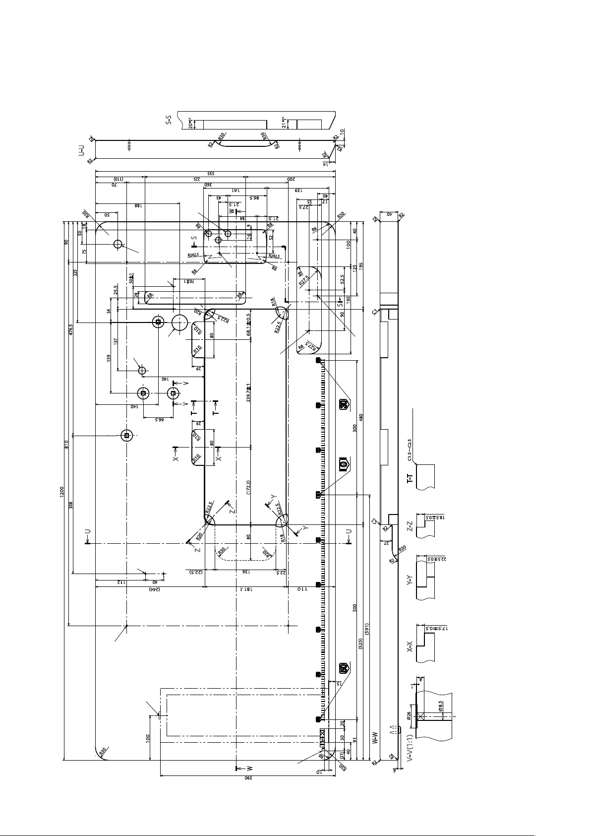
■DRAWING OF TABLE
(1) For the V-belt type
0
+0.5
S-S
20
R2
U-U
R2
(110)
70
50
R30
18
50
90
75
225
54
476.5
159
810
188
D
50±1
25.5
28
R8
137
R242.5
L
I
C
140
V
140
V
66.5
X
S
R8
70±1
R10
T
R10
E
R30
R2
535
225
360
141
43
21.5
W
R8
84
9
14
F
R8
R20
R22.5
R10
80
29
T
29
R10
80
68.1±0.5
239.7±1
X
0
+0.5
21
R30
R2
200
R8
R18
R22.5
139
55
27.5
21.5
R6
R8
R27.5
R8
86.5
R8
52
R242.5
R27.5
10
R2
R2
R2
14
40
17
40
R30
40
100
195
125
52.5
195
S
90
R2
R2
C1
H
G
2×ø3.5 depth 10
2×ø3.4 on the bottom surface, depth 10 (drill a hole at the time of set-up.)
ø35±0.5 drilled hole
JUKI logotype
2×ø3.4 on the bottom surface, depth 20
2×ø3.5 depth 4
480
(Hinge side only)
C1.5~C2.5(ひんじ側のみ)
G
H
I
J
K
L
1200
T-T
(172.2)
Y
308
U
K
112
40
(244)
A
R22.5
Z
R20
Z
R30
(22.5)
80
136
-1
181
0
R22.5
Y
R18
R30
22.5
110
15
C1
R2
U
Z-Z
27
R30
R2
Y-Y
500 300
(591)
(525)
X-X
1
18.5
±0.5
22.5±0.5
17.5±0.5
8
B
20
50
100
R30
W
390
J
R6
10
91
W-W
40
(21)
R2
R30
∅26
R2
V-V(1:1)
6
∅8.5
4×ø3.4 on the bottom surface, depth 20 (drill a hole at the time of set-up.)
Installing position of drawer stopper (on the reverse side)
ø16 depth 30
ø18 drilled hole
3×ø13 drilled hole
2×ø3.5 depth 10
A
B
C
D
E
F
– 2 –
Page 5
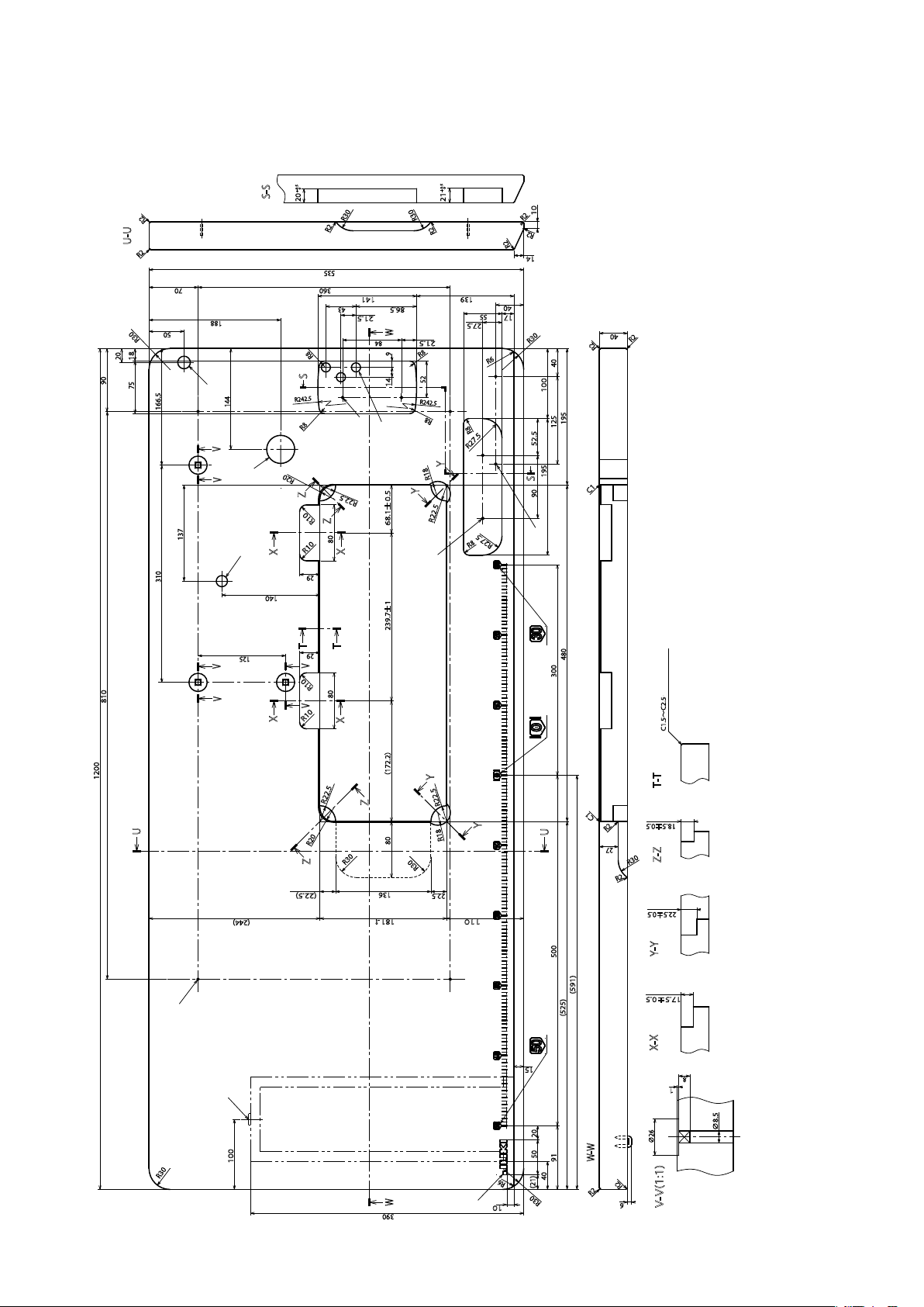
(2) For the direct-drive type
0
+0.5
S-S
20
R2
U-U
R2
70
D
188
144
R242.5
50
R30
20
18
90
75
166.5
R30
R2
535
360
141
43
21.5
WW
84
F
9
14
E
R8
S
R8
V
R20
I
V
Z
137
C
310
125
V
810
V
R10
X
140
T
V V
R10
X
R22.5
R10
Z
80
29
T
29
R10
80
68.1±0.5
X
239.7±1
X
0
+0.5
21
R30
R2
86.5
R8
52
R242.5
139
55
27.5
21.5
R6
R8
R8
R27.5
Y
R18
Y
R22.5
R8
R27.5
10
R2
R2
R2
14
40
17
40
R30
40
100
195
125
52.5
195
S
90
R2
R2
C1
H
G
2×ø3.5 depth 10
2×ø3.5 depth 10
2×ø3.4 on the bottom surface, depth 10 (drill a hole at the time of set-up.)
ø40±0.5 drilled hole
480
(Hinge side only)
C1.5~C2.5(ひんじ側のみ)
F
G
JUKI logotype
H
I
J
1200
(172.2)
Y
R22.5
Z
U
R20
Z
(22.5)
(244)
80
R30
136
-1
181
0
A
R22.5
Y
R18
R30
22.5
110
C1
U
500 300
R2
27
(591)
(525)
T-T
18.5
±0.5
Z-Z
R30
R2
22.5±0.5
Y-Y
17.5±0.5
X-X
15
8
1
B
20
100
R30
390
J
50
40
R6
(21)
R30
10
W-W
91
R2
∅26
R2
6
V-V(1:1)
∅8.5
4×ø3.4 on the bottom surface, depth 20 (drill a hole at the time of set-up.)
Installing position of drawer stopper (on the reverse side)
ø16 depth 30
ø18 drilled hole
3×ø13 drilled hole
A
B
C
D
E
– 3 –
Page 6
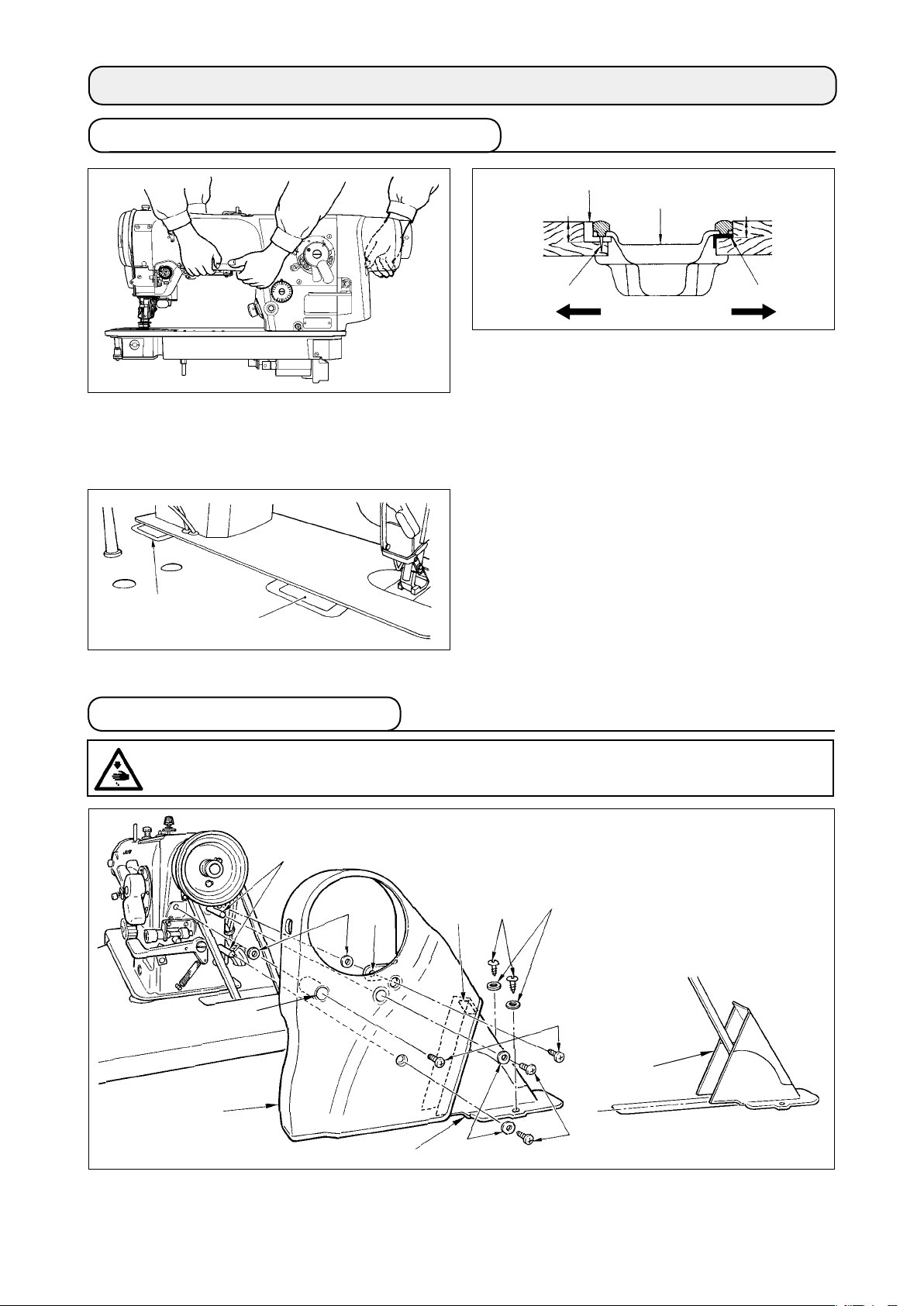
2. INSTALLATION
2-1. Installation of the sewing machine
22.5 mm
❶
❹
18.5 mm
1) Carry the sewing machine with two persons as
shown in the gure.
❷
❶
2-2. Attaching the belt cover
❷
A
B
❸
2) Attaching the oil pan
Hammer the nails ❷ on the two support rubber
seats ❶ of the machine head on operators' side
A of the protruding section of the table, and x
the two cushion seats ❸ of the machine head on
hinging side B with rubber adhesive agent. Now,
put the oil pan ❹ on the cushions.
3) Attaching the hinge
Fit the hinge ❶ in the hole in the bed and engage
it with the rubber hinge ❷ of the table. Put the
machine head down on the cushions located at
the four corners.
WARNING :
To protect against possible personal injury due to abrupt start of the machine, be sure to start the
following work after turning the power off and ascertaining that the motor is at rest.
❶
❾
❸
❼
❻
❷
A
❹
B
❼
C
❽
❺
1) Securely attach two belt cover studs ❶ to the screw holes in the machine arm.
2) Put setscrews ❸ in hole A of belt cover A ❷ and section B, and x them with setscrew washers ❹.
3) Attach belt cover A ❷ to the machine arm from the slanted rear side so that it covers the belt.
– 4 –
Page 7
4) Fix setscrews ❸ to the screw holes in the machine arm, and washers ❺ and setscrews ❻ to the belt
cover supports.
5) Insert belt cover B asm. ❼ from the rear of belt cover A ❷ and x it at the position where rubber section
C of belt cover B asm. ❼ lightly comes in contact with the belt cover A. At this time, attach the belt cover
B asm. at the position where the light and left sides are equal in terms of the long hole of the table with
wood screw ❽ and washer ❾.
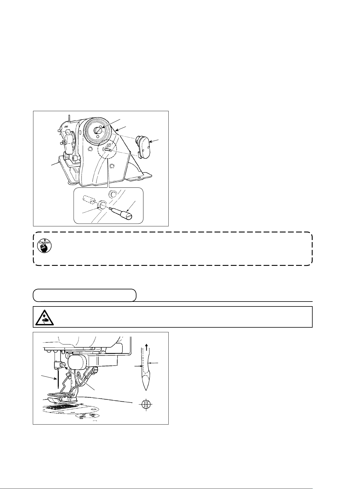
■ In case of using a market-available needle positioner
Adjust so that the needle always stops at the position higher than the cloth to make the sewing work very
effective. In this case the needle positioner can be used.
Install the needle positioner in the manner as described below.
1) Install adapter ❸ to the rear end section of the
❸
❶
❹
main shaft.
2) Loosen four setscrews in belt cover A ❶ and
temporarily tighten them.
3) Remove the setscrew in hole A among the four
setscrews and x synchronizer support ❷ to the
belt cover stud.
Then perform nal tightening of the setscrews of
the whole belt cover.
4) Attach the synchronizer ❹ of the needle position-
❷
er as shown in the gure on the left.
A
If the commercially-available needle positioner is used, a separately-available exclusive part should
be purchased.
• Synchronizer support ❷ part No. : 22535462 1 pc
• Adapter ❸ part No. : 40109125 1 pc
2-3. Inserting the needle
WARNING :
To protect against possible personal injury due to abrupt start of the machine, be sure to start the
following work after turning the power off and ascertaining that the motor is at rest.
❶
❷
B
A
1) Turn the handwheel by hand to raise the needle
bar to the highest point.
2) Loosen the needle clamp screw ❷. Hold the
needle ❶ so that the long groove B on the needle is facing exactly toward you.
3) Insert the needle deep into the hole of the needle
bar in the direction of the arrow until it will go no
further.
4) Securely tighten the screw ❷.
5) Conrm that the long groove B on the needle
faces toward you.
– 5 –
Page 8
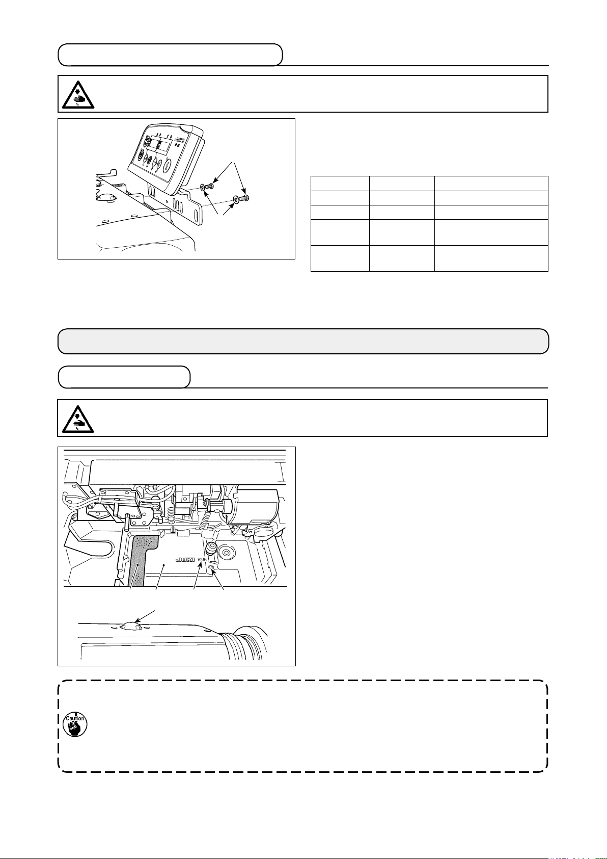
2-4. Installing the control panel
WARNING :
To protect against possible personal injury due to abrupt start of the machine, be sure to start the
following work after turning the power off and ascertaining that the motor is at rest.
In the case the sewing machine with a direct-drive
motor is used, install the control panel to the sewing
❶
❷
❶ SM4051255SP
❷ WP0501016SD
machine.
The control panel comes in four different types.
Panel Part No. Remarks
CP-18A 40088591 Simplied type
CP-180A 40088333 Multi-functional type
IT-10 40108380
IT-100 40108876
Intelligent terminal
(Simplied type)
Intelligent terminal
(Multi-functional type)
3. PREPARATION OF THE SEWING MACHINE
3-1. Lubrication
WARNING :
To protect against possible personal injury due to abrupt start of the machine, be sure to start the
following work after turning the power off and ascertaining that the motor is at rest.
1) Put foamed polyurethane pad ❶ in the oil pan ❷.
2) Fill the oil pan ❷ with JUKI CORPORATION GENUINE OIL 7 up to the level of “HIGH” mark A.
3) Add the oil as soon as the oil level comes down
to “LOW” mark B or lower.
4) Run the sewing machine after the lubrication. As
long as the machine is lubricated normally, the oil
splash is seen through the oil sight window ❸.
(The amount of splashing oil does not depend on
the amount of oil.)
❷
A B❶
❸
* If dust has gathered in the oil pan, remove it.
When changing the sewing machine oil, squeeze
urethane foam ❶ and remove dust from it.
1. Whenusinganewsewingmachineforthersttimeorusingthesewingmachinewhichhasnot
been used for a long time, run the sewing machine at a low speed (approximately 2,000 sti/min)
for approximately ten minutes.
2. When the machine is continuously used at a low speed (2,000 sti/min or less), make the machine
run idle at a high speed (4,000 sti/min or more) for approximately 5 minutes once a week.
3. Use clean oil and when the oil becomes dirty, replace it with clean oil as soon as possible. When
you continue to use the machine with dirty oil, the trouble will be caused.
– 6 –
Page 9
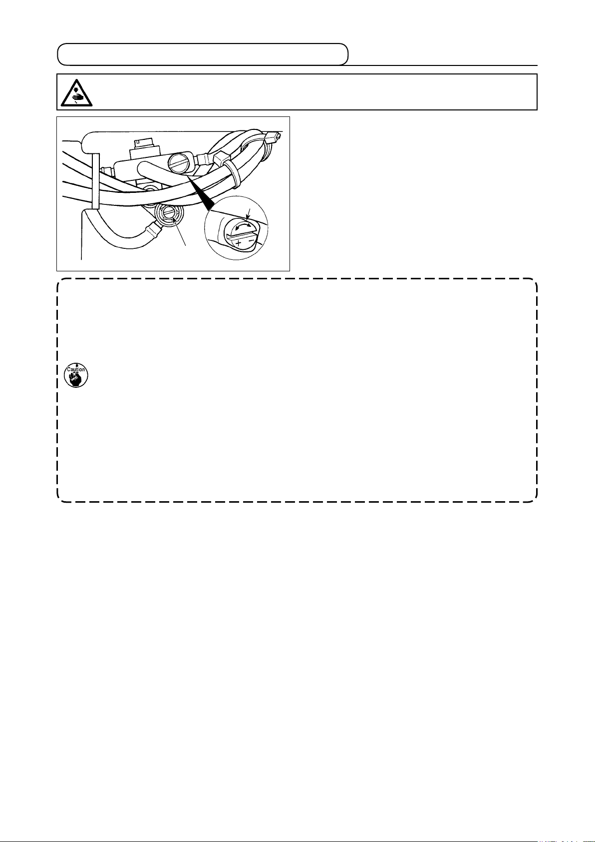
3-2. Adjusting the amount of oil in the hook
WARNING :
To protect against possible personal injury due to abrupt start of the machine, be sure to start the
following work after turning the power off and ascertaining that the motor is at rest.
Tilt the machine head, and adjust the amount of oil in
the hook by turning the oil amount adjustment screw
❶ mounted on the gear box B.
Turn the adjusting screw in the “+” direction (counter-
clockwise) to increase the amount of oil in the hook.
❶
❷
1. After the adjustment, idle the sewing machine at the sewing speed to be used for sewing about
30 seconds. Then, check the oil quantity by comparing with the sample which shows the appro-
priate oil splash (marks).
2. When adjusting the amount of oil in the hook, perform the adjustment in a way of reducing the
oil amount after somewhat increasing it.
3. The amount of oil in the hook has been adjusted at the max. sewing speed at the time of delivery.
When you always use the sewing machine at low sewing speed, there is a possibility that trouble
occurs due to the lack of amount of oil in the hook. When the sewing machine is used always at
low sewing speed, perform the adjustment of the amount of oil in the hook.
4. There is a possibility of causing oil leakage from the hook shaft section since oil does not return
to the oil tank when oil amount adjustment screw ❶ is used in fully-tightened state. Do not use
the screw in fully-tightened state. In addition, when the amount of oil in the hook is not obtained
unless oil amount adjustment screw ❶ is near in fully-tightened state, it is considered that hook
shaft oil wick (JUKI Part No. 11015906) is clogged or the like. Replace the hook shaft oil wick.
5. Never adjust screw ❷ofthehookoilquantityadjustingvalvesinceitisxed.
Turn the adjusting screw in the “–” direction (clockwise)
to decrease it.
– 7 –
Page 10

3-3. Adjusting the amount of oil (oil splashes)
WARNING :
Be extremely careful about the operation of the machine since the amount of oil has to be checked
by turning the hook at a high speed.
(1)Conrmationoftheamountofoilinthehook
①Amountofoil(oilsplashes)conrmationpaper
Approx. 25 mm
Approx. 70 mm
* Use any paper available regardless of the material.
② Positiontoconrmtheamountofoil(oilsplashes)
Approx. 10 mm
Oilsplashesconrmationpaper
Hook
* Whencarryingouttheproceduredescribedbelowin1)and2),conrmthestatethattheneedle
thread from the thread take-up lever to the needle and the bobbin thread are removed, the presser
foot is lifted and the slide plate is removed. At this time, take extreme caution not to allow your
ngerstocomeincontactwiththehook.
1) If the machine has not been sufciently warmed up for operation, make the machine run idle for approxi-
mately three minutes. (Moderate intermittent operation)
2) Place the amount of oil (oil spots) conrmation paper under the hook immediately after the machine stops
running.
3) Conrm the height of the oil surface in the oil reservoir is within the range between “HIGH” and “LOW”.
4) Conrmation of the amount of oil should be completed in ve seconds. (Check the period of time with a
watch.)
(2) Sample showing the appropriate amount of oil in the hook
Appropriate amount of oil (small)
Splashes of oil from the hook
Min. 0.5 mm
Appropriate amount of oil (large)
Splashes of oil from the hook
Max. 1 mm
1) The amount of oil shown in the samples on the left should be nely adjusted in accordance with sewing
processes.
Be careful not to excessively increase/decrease the amount of oil in the hook. (If the amount of oil is too
small, the hook will be seized (the hook will be hot). If the amount of oil is too much, the sewing product
may be stained with oil.)
2) Adjust the amount of oil in the hook so that the oil amount (oil splashes) should not change while checking
the oil amount three times (on the three sheets of paper).
– 8 –
Page 11

3-4. Winding the bobbin thread
WARNING :
To protect against possible personal injury due to abrupt start of the machine, be sure to start the
following work after turning the power off and ascertaining that the motor is at rest.
1) Insert the bobbin deep into the bobbin winder
spindle ❺ until it will go no further.
2) Pass the bobbin thread pulled out from the spool
rested on the right side of the thread stand follow-
ing the order as shown in the gure on the left.
Then, wind the end of the bobbin thread on the
bobbin several times.
3) Press the bobbin winder trip latch ❻ in the direction of A and start the sewing machine. The
bobbin rotates in the direction of C and the bobbin
thread is wound up. The bobbin winder spindle
❺ will automatically stop as soon as the winding
is nished.
4) Remove the bobbin and cut the bobbin thread
with the thread cut retainer ❶.
5) To adjust the winding amount of the bobbin thread,
loosen the setscrew ❼ and move the bobbin
winder trip latch ❻ to the direction A or B. Then,
tighten the setscrew ❼.
To the direction D : Decrease
To the direction E : Increase
❼
B
❻
E
C
D
❶
A
❺
❸
❷
6) In case that the bobbin thread is not wound even-
❷
ly on the bobbin, loosen the nut ❹ and turn the
bobbin thread tension to adjust the height of the
thread tension disk ❷.
• It is the standard that the center of the bobbin
F
❷
❹
• Move the position of the thread tension disk ❷
is as high as the center of the thread tension
disk ❷.
to the direction F as shown in the gure on the
G
❷
left when the winding amount of the bobbin
thread on the lower part of the bobbin is excessive and to the direction G as shown in the
gure on the left when the winding amount of
the bobbin thread on the upper part of the
bobbin is excessive.
After the adjustment, tighten the nut ❹.
7) Turn the thread tension nut ❸ to adjust the tension
of the bobbin thread winder.
❸
– 9 –
Page 12

3-5. Inserting the bobbin case and the bobbin
WARNING :
To protect against possible personal injury due to abrupt start of the machine, be sure to start the
following work after turning the power off and ascertaining that the motor is at rest.
Placing a bobbin into the bobbin case
1) Take a bobbin by your right hand with the thread
drawn out about 5 cm and place it into the bobbin
③
②
①
case as illustrated.
2) Thread the bobbin case in the order of the num-
bers and pull it out through the thread path as il-
lustrated.
3) When the bobbin is correctly loaded in the bobbin
case, the bobbin rotates in the direction of the
arrow when the thread is pulled.
❶
❶
Inserting and removing the bobbin case
1) Turn the handwheel by hand to raise the needle
to the highest point.
2) Raise the bobbin case latch ❶ and hold it between
your two ngers as shown in the gure on the left.
3) Insert the bobbin case as it is being held into the
sewing hook shaft as far as it will go by putting
your hand from the under of the oil reservoir.
4) Release the bobbin case latch to let it steadily
rest in the closing position.
* Reverse the above procedures when removing
the bobbin case.
How to use the bobbin case thread hole
1) For normal sewing, use hole A. To increase the
thread tension when the needle throws to the left,
use hole B. (Hole C is intended for special pro-
cesses.)
C
B
A
There may be a case where several stitch-
esatthestartofsewingaredifculttobe
knotted when thread trimmer is used with
thinlament threadsuch as (#50,#60 or
#80) using hole B.At this time,use the
other hole or perform the sewing starting
from the right.
– 10 –
Page 13

3-6. Threading the machine head
WARNING :
To protect against possible personal injury due to abrupt start of the machine, be sure to start the
following work after turning the power off and ascertaining that the motor is at rest.
❶
LZ-22**A-7 LZ-22**A
❹
❺
❷
❸
1) Turn the handwheel by hand to raise the needle to the highest point.
2) Pass the thread in the order of the numbers as illustrated.
3) Pull out the thread about 10 cm from the needle after passing it through the needle.
3-7. Adjusting the pedal
WARNING :
To protect against possible personal injury due to abrupt start of the machine, be sure to start the
following work after turning the power off and ascertaining that the motor is at rest.
❶
❸
❷
(1) Attaching the connecting rod
1) Move the pedal adjusting plate ❸ in the direction
of the arrow to make the motor control lever ❶
and the pedal connecting rod ❷ straight.
(2) Inclination of the pedal
1) Inclination of the pedal can be adjusted by changing the length of the pedal connecting rod ❷.
2) Loosen the adjusting screw ❹, and move up or
down the connecting rod ❷ to change its length
as desired.
❹
– 11 –
Page 14

4. ADJUSTING THE SEWING MACHINE
4-1. Adjusting the thread tension
WARNING :
In case of thread-breakage, it may occur that the thread tangles on the thread take-up lever. In such
a case, turn the power off, raise the thread take-up cover and remove the thread which has twined
around the thread take-up. At this time, be extremely careful to protect your hand from being cut by
the knife.
(1) Adjusting the needle thread tension
1) Adjust the needle thread tension using the tension
nut ❶.
Turning the tension nut clockwise increases the
❷
❸
F
❶
❹
❺
needle thread tension, or counterclockwise decreases it.
1. If the thread tension of pre-tension ❷ is
too low, the thread may slip out of rotary
disc ❸. Adjust the thread tension of the
pre-tension, using pre-tension adjusting
nut ❹ taking care of tension balance between the pre-tension and the rotary disc.
2. When setting the needle thread tension,
draw the thread in the direction F to
check that rotary disc ❸ smoothly rotates
with no slippage.
If the rotary disk slips, tighten pretension
adjusting nut ❹.
3. Thread tension disc felt ❺ is a consumable part.
When rotary disc ❸ slips, there is a possibility that the thread tension disc felt has been con-
sumed. Replace the felt with new one (Part No. : 22528509 x 4 pcs.).
4. Whenthickthread(approximately#30orlower)isusedforneedlethread,threadtensionisapt
tobeinsufcientwiththerotarytensioncontrollerofthestandarddelivery.Inthiscase,usethe
optional thread tension disk asm. (part No. : 40017095).
❷
(2) Adjusting the thread take-up spring
1) To change the tension of the thread take-up
spring, rmly tighten the screw ❶ which fastens
❸
the tension post socket to the machine arm and
insert the blade of a screwdriver into the slot in
the tension post ❷ to adjust the tension of the
thread take-up spring.
Turn it clockwise to increase.
Turn it counterclockwise to decrease.
2) To change the amount of thread taken by the
❶
thread take-up spring, loosen the clamping screw
❶ of the tension post socket and turn the tension
post socket ❸.
❶
Adjustable range of the amount of thread taken
by the thread take-up spring : 6 to 10 mm
(3) Adjusting the bobbin thread tension
1) The tension of the bobbin thread is adjusted by
turning the tension adjusting screw ❶.
Turn it clockwise to increase.
Turn it counterclockwise to decrease.
– 12 –
Page 15

4-2. Adjusting the zigzag width
WARNING :
To protect against possible personal injury due to abrupt start of the machine, be sure to start the
following work after turning the power off and ascertaining that the motor is at rest.
❸
❶
(1) Adjusting the zigzag width
The zigzag width is adjusted by the knob ❶.
1) Push the lever ❷ with your nger.
2) Turn the knob as you are pushing the lever and
❺
set the pointing line to a desired zigzag width
which is indicated by the zigzag width scale ❸ in
❹
❷
mm.
3) Release the lever, and the knob will be locked up
in the given position.
* For the LZ-2284A and -2287A, the needle throwing width has been factory-set
to 8 mm at the time of shipment. It should be noted, however, the needle
throwing width can be increased to 10 mm at the maximum by changing the
Presser foot 22580369
Throat plate 10041010
Feed dog 10047017
throat plate and feed dog and changing the location of stopper screws ❹
and ❺. In this case, adjust the height of the needle bar so that the blade
point of the hook passes the upper end of the needle eyelet when the needle throws to the leftmost end of its zigzag stroke. In the case the needle
throwing width exceeds 8 mm, however, the sewing machine should be
operated at 4,000 sti/min or less.
1. Take care not to tighten the screws ❹ and ❺toormcausingthebreakageoftheknob❶.
2. For the LZ-2284A, the maximum needle throwing width of the standard zigzag stitching is 5 mm.
3. It is necessary to bring the needle bar to its upper stop position to carry out adjustment of the
needle throwing width. Turn the handwheel by hand to check that the needle does not interfere
with the presser foot.
Left
pattern
❶
❷
Right
pattern
❷
❸
❶
(2) Pattern inversion adjustment
* In the case the LZ-2287A is used for sewing a
scallop pattern, the pattern can be inverted.
Normally, the right pattern is sewn.
1) Push the lever ❷ with your nger.
2) Turn the knob as you are pushing the lever and
set the pointing line to a desired zigzag width
which is indicated by the zigzag width scale ❸ in
mm.
3) Release the lever, and the knob will be locked up
in the given position.
(3) Adjusting the needle position
* JUKI models LZ-2280A, -2284A and -2287A
have the needle position changing lever by
which the needle position can be changed as
desired.
To change the needle entry point, move needle position
changing lever ❶ as shown in the gure.
For the LZ-2284A, loosen screw ❷ and move needle
position changing lever ❶ to adjust the needle entry
point. After the adjustment, tighten screw ❷.
LZ-2280A, 2284A, 2287A
– 13 –
Page 16

4-3. Adjusting the pressure of the presser foot
WARNING :
To protect against possible personal injury due to abrupt start of the machine, be sure to start the
following work after turning the power off and ascertaining that the motor is at rest.
1) Turn the presser spring regulator ❶ clockwise A
to increase the pressure given by the presser foot.
2) Turn the presser spring regulator counterclockwise B to decrease it.
* Height C of the presser spring regulator ❶
can be measured by reading the scale mark
of presser spring regulator ❶ on top surface
D of nut ❷. Use the measurement for the
management of sewing processes, etc.
❷
C
B
A
❶
D
4-4. Adjusting the height of the presser bar
WARNING :
To protect against possible personal injury due to abrupt start of the machine, be sure to start the
following work after turning the power off and ascertaining that the motor is at rest.
1) Adjust the height of the needle bar by loosening
❸
❷
presser bar bracket setscrew ❶ when adjustment
is necessary.
2) After the adjustment, securely tighten the screw.
❶
A
B
In order to prevent the needle breakage due
to interference between the needle and the
presser foot, adjust so that the clearance
between needle hole ❷ in the presser foot
and needle hole ❸ in the throat plate is
equal at both sides (A = B). Then, tighten
setscrew ❶.
4-5. Adjusting the micro-lifting mechanism of the presser foot
WARNING :
To protect against possible personal injury due to abrupt start of the machine, be sure to start the
following work after turning the power off and ascertaining that the motor is at rest.
❶
❷
Some type of material needs to be sewn with the
presser foot slightly lifted.
In this case, perform this adjustment following the
procedure described below.
1) Loosen nut ❷. Turn the micro-lifter oating amount
by turning the micro-lifter oating screw ❶
2) Turn presser foot oating screw ❶ clockwise until
the presser foot goes up by the required amount.
Then, tighten nut ❷ to x the presser foot.
If you do not use the micro-lifting mechanism of the presser foot, fully return the
presser foot micro-lifting screw ❶ to its
home position. The standard of lifting
amount of the presser foot is as thick as a
sheet of paper.
.
– 14 –
Page 17

4-6. Adjusting the stitch length
A
❶
❷
1) Turn the stitch length dial ❶ in the direction of the
arrow so that the number corresponding to the
desired stitch length meets the marker dot A
engraved on the machine arm.
2) Numbers on the stitch length dial are calibrated
in “mm”.
3) To change the stitch length from a larger value to
a small value, turn the stitch length dial ❶ while
pressing the feed lever ❷ in the direction of the
arrow.
To perform reverse feed stitching, press down the
feed lever ❷. The sewing machine performs re-
verse feed stitching as long as you keep the feed
lever held pressed. The feed lever will return to
its home position and the sewing machine will run
in the normal stitching direction when you release
the feed lever.
* The graduations on the dial are mere reference.
So, adjust the denser stitching while actually
observing the nished seam.
4-7. Adjusting the denser stitching
❶
Stitch length can be reduced at the start or end of
sewing. This feature is used for fastening stitch.
1) Feed lever is moved by turning the dial while
keeping the feed lever held depressed. Adjust the
stitch pitch for condensation stitching while ob-
serving the scale mark which aligns with marker
line ❶ on the top surface of the lever.
2) Turn the dial in the “+” direction to reduce the
reverse feed stitch length (i.e. the feeding direction
gradually changes to the normal one).
“+2” means “normal feed stitch length is 2 mm”
and “–2” means “reverse feed stitch length is 2
mm”.
* For the LZ-2280AB, +5 means "forward feed
by 5 mm" and -4 means "reverse feed by 4
mm".
3) The denser stitching can be adjusted under the
normal stitching mode (when the one-touch type
reverse feed switch is actuated, the feed will not
move in the reverse direction but the normal feed
stitch length will be reduced).
* The graduations on the dial are mere reference.
So, adjust the denser stitching while actually
observing the nished seam.
– 15 –
Page 18

4-8. Height and inclination of the feed dog
WARNING :
To protect against possible personal injury due to abrupt start of the machine, be sure to start the
following work after turning the power off and ascertaining that the motor is at rest.
❶
❷
❸
❹
1.1 mm
❹
❷
B
A
Throat plate spacer (part No. : 22503908)
Feed bar spacer (part No. : 10025906)
To secure a space
Counter knife Feed dog
(1) Height of the feed dog
1) To adjust the height of the feed dog, loosen the
screw ❶ and turn the feed driving link shaft ❷
using a screwdriver.
2) The standard height of the feed dog is 1.1 mm.
(Reference) Marker dot A on feed driving link
shaft ❷ and marker dot B on feed
bar shaft ❹ should respectively face
inward.
3) To adjust the inclination of the feed dog, loosen
the screw ❸ and turn the feed bar shaft ❹ inserting a screwdriver through the adjustment hole in
the machine bed.
4) For the machine with a thread trimmer, there can
be no space between the counter knife and the
underside of the feed dog when adjusting the feed
mechanism (change in height and timing) or using
a commercially-available feed dog.
In this case, place a feed bar spacer (part number
: 10025906) under the feed mechanism and a
throat plate spacer (part number : 22503908)
under the throat plate so as to secure a space
between the counter knife and the underside of
the feed dog.
(2) Inclination of the feed dog
The standard inclination of the feed dog is ob-
tained by adjusting so that the feed dog becomes
level when the feed dog reaches its highest position.
4-9. Attaching/removing the hook
WARNING :
To protect against possible personal injury due to abrupt start of the machine, be sure to start the
following work after turning the power off and ascertaining that the motor is at rest.
❸
❹
❶
❷
A
B
The hook is exclusively designed to the LZ-2280A Series model of sewing machine.
When placing an order for the hook in case of replacement or the like, designate it with its part
number. Hook: 22525877
When you replace the sewing hook, remove it in the
following procedures;
1) Turn the handwheel until the needle reaches to
its highest position.
2) Remove the needle, presser foot, throat plate,
feed dog and bobbin case from the machine.
3) Remove the setscrew ❶ and take out the bobbin
case positioning nger ❷.
4) Loosen the two screws ❹ and remove the sewing
hook ❸.
* Reverse the above procedures when inserting the
sewing hook.
At this time, make sure that top end A of the
bobbin case positioning nger is aligned with line
B as shown in the gure on the left. Never let A
protrude from line B.
– 16 –
Page 19

4-10. Adjusting height of the needle bar
WARNING :
To protect against possible personal injury due to abrupt start of the machine, be sure to start the
following work after turning the power off and ascertaining that the motor is at rest.
1) Set the zigzag width to “0”. Bring the needle to
the center of the zigzag stroke.
❷
2
1
❶
1. Thickness of the semicircle plate ❷ is different from that of the throat plate. So, be sure to use
the semicircle plate ❷ when adjusting the height of the needle bar.
Be sure to perform the adjustment with zigzag width set to zero and with the needle positioned
at the center of the zigzag stroke.
2. For the LZ-2280AA, timing gauge D should be used.
For the LZ-2280AB, -2284A* and -2287A, timing gauge E should be used.
2) Remove the presser foot, throat plate, semicircle
plate ❷ and feed dog.
3) Place half-moon shaped plate ❷ on the throat-
plate installing surface of the bed. Loosen setscrew ❶. Adjust so that the distance from the top
surface of the half-moon shaped plate ❷ to the
bottom end of the needle bar equals to the height
of timing gauge 1.
4-11. Adjusting the needle-to-hook timing and the needle guard
WARNING :
To protect against possible personal injury due to abrupt start of the machine, be sure to start the
following work after turning the power off and ascertaining that the motor is at rest.
0 to 0.05 mm
1
2
(2) Conrmation
In the case of the maximum needle throwing width (adjustment at the time of shipment: LZ-2280AA: 4 mm;
Other models: 8 mm), check to be sure that the distance from the top end of the needle eyelet to the blade
point of the hook is 0.2 to 0.5 mm while the needle throws to the left.
* If the zigzag width of 10 mm is used or the shape of indented part of the needle is different from that of
indented part of the needle at the time of delivery, re-adjust the height of the needle bar.
(3) Adjusting the needle guard
1) Maximize the zigzag width. Bend the needle guard to adjust so that the needle does not come in contact
with the blade point of the both at the leftmost and rightmost positions of the zigzag stroke. At this time,
adjust the clearance provided between the needle and the blade point of the hook to 0 to 0.05 mm.
2) The needle guard functions to keep the needle away from the blade point of the hook, thereby preventing
damage to the blade point of the hook. Whenever you have replaced the hook with a new one, be sure to
adjust the position of the needle guard.
(1) Positioning the hook
1) After the completion of the adjustment of the
needle bar height, adjust the hook using timing
gauge 2 so that the blade point of the hook is
aligned with the center of the needle.
2) At this time, the blade point of the hook should
slightly come in contact with the needle when the
needle guard does not touch the needle.
When thread breakage has occurred, there is a case where thread is caught in the hook.
Be sure to perform sewing after removing the thread caught in the hook.
– 17 –
Page 20

4-12. Adjusting the stop position of the needle
WARNING :
1. Turn OFF the power before starting the work so as to prevent accidents caused by abrupt start of
the sewing machine.
2. Do not perform switch operations other than those described in the following explanations.
3. Be sure to re-turn the power switch ON after one second or more has passed. If the power is turned
ON immediately after turning it OFF, the sewing machine may not work normally. In this case, turn
ON the power again.
(1) Stop position after thread trimming
1) The standard needle stop position is obtained by
aligning marker dot A on the pulley cover with
white marker dot B on the handwheel.
* For the details, refer to the Instruction Manual for
the control box together.
A
D
B
C
E
F
down stop position
* When the panel other than CP-18 is used, refer
to the explanation of each panel.
1) Turn OFF the power to the machine.
2) Turn the power ON while pushing the switch ❺
on the operation panel.
3) The screen display E indicates the setting No.
(2) Adjusting procedure of the needle up/
❶
❷
❸
❺❹
96 and F indicates the sewing speed. (When the
screen display is not changed, operate again
steps 1) and 2).
4) Update the setting No. by switch ❶ or switch ❷.
Setting No. 121 : Needle UP stop position
Setting No. 122 : Needle DOWN stop position
5) Specify the setting contents F within the range of -15 to 15 with switch ❸ or switch ❹.
(Standard is "0". The numeric of set value indicates the approximate rotating angle. (When the numeric is
set to the "+" direction, the needle UP stop position is lowered. (Direction C)
When the numeric is set to "–" direction, the needle UP stop position is raised. (Direction D)
6) After completion of the setting, press switch ❶ or switch ❷ to determine the updated value. (When turning
OFF the power to the machine before performing this work, the contents are not updated.)
7) After completion of the operation, turn OFF the power to the machine. The normal operation can be per-
formed by turning ON the power to the machine again.
– 18 –
Page 21

4-13. Adjusting the thread trimmer
WARNING :
To protect against possible personal injury due to abrupt start of the machine, be sure to start the
following work after turning the power off and ascertaining that the motor is at rest.
(1) Initial position of the moving knife
When the moving knife is in its initial position, the
moving knife pin ❶ should be aligned with the engraved marker dot ❷ as shown in the gure on the
❶
❷
❶
❷
left.
1. When the gauge size which is more than
that delivered as standard or the gauge
size of other manufactures is used, and
the counter knife interferes with the feed
dog, loosen nut ❸, move the initial position of moving knife pin ❶ to the left from
engraved maker dot ❷ by approximately
one half of engraved marker dot ❷ and
xthepin.
2. Guarantee of the sharpness of the thread
trimmer knife unit is #80 to #50. When
using thick threads thicker than these
Nos., replace the knife with thread trim-
mer knife unit for thick thread (Part No. :
22556054).
❹
❸
❶
❺
❷
If the initial position of the moving knife is not
correct
Loosen the nut ❸, and move the moving knife to the
right or left until the pin ❶ meets the marker dot ❷.
Then, tighten the nut ❸.
(2) Adjusting the thread trimming timing
Put the roller ❹ in the cam groove. Now, gradually turn
the handwheel in the reverse direction. The handwheel
will go no further when the marker dot ❶ engraved on
the pulley cover is aligned with the green marker dot
❷ engraved on the handwheel.
To adjust the thread trimming cam, align the green
marker dot on the pulley cover with the red marker dot
on the handwheel, put the roller in the groove of the
thread trimming cam, and turn the handwheel in the
direction opposite to the direction of rotation of the
hook driving shaft until it will go no further. Now, tighten the two screws ❺.
– 19 –
Page 22

4-14. Needle thread feeding device
WARNING :
To protect against possible personal injury due to abrupt start of the machine, be sure to start the
following work after turning the power off and ascertaining that the motor is at rest.
❶
❶
8 to 10 mm
❷
❷
❺
❹
(1) Position of the feeding wire
Adjust the installing position of the feeding wire ❶ so
that a distance of 8 to 10 mm is provided between the
guide portion ❷ of the thread guide and the top end
of the wire. Then, tighten the two screws ❸.
❸
At this time, adjust the longitudinal position of thread draw-out wire ❶ so that
thread draw-out wire is brought to the approximate center of thread take-up thread
guide ❷.
(2) Adjusting the stroke of the feeding wire
1) Increase the feeding amount of the needle thread
if the needle thread fails to interlace with the
bobbin thread or is likely to slip out of the needle
eyelet at the start of sewing.
2) Loosen two setscrews ❹. Shift thread draw-out
wire ❶ in the direction of the arrow.
If the feeding amount of the needle thread is
excessive, the thread will be likely to break.
(3) When turning OFF the feeding device
If it is not necessary to operate thread draw-out wire
❶, turn off draw-out switch ❺ on the rear face of the
sewing machine.
4-15. Position of the wiper
WARNING :
To protect against possible personal injury due to abrupt start of the machine, be sure to start the
following work after turning the power off and ascertaining that the motor is at rest.
1) Align the marker dot ❶ engraved on the pulley
cover with the white marker dot ❷ engraved on
❶
❷
❸
❺
2 mm
❹
❻
the handwheel (the 3rd white marker dot in terms
of the direction of rotation of the sewing machine).
2) Move the rod ❸ in the direction of the arrow, and
adjust the clamping screw ❺ so that an approxi-
mate 2 mm clearance is provided between the
top end of the needle and the wiper ❹.
3) For the sewing machine provided with a wiper,
turn off wiper seesaw switch ❻ in the case the
wiper is not necessary to be used.
– 20 –
Page 23

5. OPERATION OF THE SEWING MACHINE
5-1. How to operate the pedal (In the case of the direct-drive type sewing machine)
The pedal is operated in the following four steps:
A
B
C
D
E
* Thread trimming operation is only carried out on the sewing machine provided with a thread trimmer.
* When the auto-lifer (AK device) is used, one more operating switch is provided between the sewing ma-
chine stop switch and thread trimming switch.
The presser foot goes up when you lightly depress the back part of the pedal D, and if you further depress
the back part, the thread trimmer is actuated. When starting sewing from the state that the presser foot
has been lifted with the Auto-lifter and you depress the back part of the pedal, the presser foot only comes
down.
• If you reset the pedal to its neutral position during the automatic reverse feed stitching at seam start, the
machine stops after it completes the reverse feed stitching.
• The machine will perform normal thread trimming even if you depress the back part of the pedal immediately following high or low speed sewing.
• The machine will completely perform thread trimming even if you reset the pedal to its neutral position
immediately after the machine started thread trimming action.
1) The machine runs at low sewing speed when you
lightly depress the front part of the pedal. B
2) The machine runs at high sewing speed when
you further depress the front part of the pedal. A
(If the automatic reverse feed stitching has been
preset, the machine runs at high speed after it
completes reverse feed stitching.)
3) The machine stops (with its needle up or down)
when you reset the pedal to its original position.
C
4) The machine trims threads when you fully depress
the back part of the pedal. E
5-2. One-touch type reverse feed switch
* Only for the sewing machine provided with a onetouch type reverse feed stitching function
(1) How to use the reverse feed switch
1) Press down the switch ❶, and the machine will
immediately run in the reverse direction.
2) Reverse stitching is performed as long as you
❶
WARNING :
To protect against possible personal injury due to abrupt start of the machine, be sure to start the
following work after turning the power off and ascertaining that the motor is at rest.
❷
keep the switch held pressed down.
3) Release the switch, and the machine will immediately run in the normal direction.
* If you purchase the option kit, it can be retro-tted
to the sewing machine to carry out one-touch type
manual reverse feed stitching. (One-touch type
manual reverse feed stitching kit, part number:
40135177)
(2) Position of the reverse feed switch
The position of the switch can be adjusted to an
easy-to-operate position, according to the sewing
process.
1) Loosen screws ❷ on the rear face of the sewing
machine. Then, adjust the position of the switch.
– 21 –
Page 24

5-3. Changing over the needle-throwing method
WARNING :
To protect against possible personal injury due to abrupt start of the machine, be sure to start the
following work after turning the power off and ascertaining that the motor is at rest.
LZ-2284A
LZ-2287A
C
3-step zigzag
❶
❸
A
B
Standard zigzag
Scallop zigzag
C
For the LZ-2284A, needle-throwing method is select-
able between the standard zigzag stitching and 3-step
zigzag stitching. For the LZ-2287A, it is selectable
between the 3-step stitching and scallop zigzag stitch-
ing.
1) Turn the handwheel to respectively align marker
dot C with the following.
* LZ-2284A: Toward thread take-up knife A
* LZ-2287A: Toward the lower end of the needle
bar B
2) Pull changeover lever ❶ toward this side and pull
out lock pin ❷ from positioning hole ❹.
3) Slightly turn the handwheel forward and backward
to turn change-over lever ❶ so that the lever
aligns with desired zigzag mark ❸ to nd the
change-over point.
4) At the change-over position, securely insert lock
pin ❷ into positioning hole ❹ to complete the
setting.
5) If the pattern cannot be changed over, give the
handwheel a turn and repeat the aforementioned
steps from 1).
Make sure that lock pin ❷ is securely
placed in positioning hole ❹.
In addition, never operate the sewing machine in the state that lock pin ❷ is not
placed in positioning hole ❹ (on the way
of changeover). It will cause the trouble of
the sewing machine.
❷
❹
5-4. LED light
The LZ-2284A with a direct-drive motor is provided
with an LED light.
1) The brightness of the LED light with brightness
adjustment switch ❶ shown in the gure at the
left. (In three steps)
[Brightness: High → Medium → Low → OFF]
2) When the LED light is re-turned on after it has
been turned off, the brightness returns to "High".
❶
– 22 –
Page 25

6. OPTIONAL
6-1. Pedal-operated reverse feed device (RF-1)
When you sew bulky materials, it is not easy to operate
the feed lever with your right hand to make the machine
perform reverse feed stitching.
In this case, attach the RF-1 device to your sewing
machine. This device allows you to reverse the sewing
directions as desired with your foot instead of your right
hand.
The gure on the left shows the device installed on the
sewing machine. When using the device, be sure to
replace the feed lever tension spring (B1646555000)
mounted on the machine with the spring (MAT80117S00)
supplied with the RF-1.
GRF01001000
49mm
20mm
ø10mm
6-2. Joining foot for the lockstitch presser foot
To use the presser foot for lockstitch, the "joining foot
for the lockstitch presser foot" has to be used.
❶ Joining foot for the lockstitch presser foot (Part
No.: D1551586000)
❶
❷
❷ Setscrew (Part No.: SS7090910SP)
6-3. Auxiliary thread take-up kit
In the case the sewing machine is used for blind stitching and high-speed sewing processes, it is recommend-
ed to use the "auxiliary thread take-up kit" which helps stabilize the needle thread loops.
Thread breakage and stitch skipping can be prevented by stabilizing the needle thread loops.
* Auxiliary thread take-up kit Part No.: 40135178
– 23 –
Page 26

7. MOTOR PULLEY AND BELT
(1) In the case of the belt type sewing machine
1) The driving motor of this machine is a 450 watts (2P) clutch motor.
2) Use the M type V belt.
3) The attainable sewing speeds are determined by the diameter of the motor pulley and the length of the
belt as listed below.
Outer diameter of
motor pulley (mm)
135 MTSP0135000A 5,480 130 MTSP0130000A 5,270 125 MTSP0125000A 5,060 -
115 MTSP0115000A 4,630 110 MTSP0110000A 4,440 5,330
105 MTSP0105000A 4,250 5,040
100 MTSP0100000A 4,000 4,780
95 MTSP0095000A 3,820 4,540
90 MTSP0090000A 3,610 4,320
85 MTSP0085000A 3,390 4,000
80 MTSP0080000A 3,160 3,790
75 MTSP0075000A 2,950 3,520
70 MTSP0070000A 2,740 3,260
65 MTSP0065000A 2,530 3,020
60 MTSP0060000A 2,320 2,760
Motor pulley part No.
Sewing speed (sti/min) Belt length
50 Hz 60 Hz
(2) In the case of the direct-drive type sewing machine
1) Be sure to use the control box, SC-920A (Ver. 04 or later).
mm (inch)
1,168 (46) MTJVM004600
1,143 (45) MTJVM004500120 MTSP0120000A 4,850 -
1,118 (44) MTJVM004400
1,092 (43) MTJVM004300
1,067 (42) MTJVM004200
Belt part No.
– 24 –
Page 27

8. TROUBLES AND CORRECTIVE MEASURES
Trouble Cause Corrective measures
Thread
breakage
Stitch
skipping
Loose stitch①When the needle thread tension is too low. Increase the needle thread tension. 12
When the thread gets entangled in the thread take-up lever.
①
When the needle thread is threaded in a wrong way. Thread it correctly. 11
②
When the thread gets entangled in the sewing hook. Remove the entanglement. 17
③
When the needle thread is excessively tight or loose. Adjust the thread tension. 12
④
When the needle thread slips in the rotary tension.
⑤
When the tension of the thread take-up spring is
⑥
excessively high or low.
When the stroke of the thread take-up spring is
⑦
excessively large or small.
When the timing of the sewing hook and the needle is
⑧
not matched.
When there is a scratch on the thread path of hook,
⑨
bobbin case, thread take-up lever or any other part.
When the thread is not suitable.
⑩
a. The quality of the thread is poor. Use a thread of good quality.
b. The thread is too thick for the needle. Use a suitable thread or needle.
c. The thread is broken by heat. Use JUKI Silicone Oil Lubricant unit.
When the stitch is skipped. Refer to the following paragraphs,
⑪
When the needle is inserted in a wrong way.
①
a.
The needle is not entirely inserted into the needle bar.
b. The needle eye is not facing straight to the operator. Let the needle eye face straight to the
c. The needle is facing backwards. Let the long groove on the needle face
When the needle itself is not suitable.
②
a. The needle is bent. Replace it with a new needle. 5
b. The quality of the needle is not good. Use a needle of good quality.
c. The needle is too thin for the thread. Use a suitable needle or thread.
d. Blunt needle is used. Replace it with a new needle. 5
When the hook blade point is not sharp enough or
③
damaged.
When the timing of the sewing hook and the needle is
④
not matched.
When the height of the needle bar is not correct. Adjust the height of the needle bar. 17
⑤
When the clearance between the needle and the sewing
⑥
hook is too great.
When the tension of the thread take-up spring is too low. Increase the tension of the spring. 12
②
When the tension of the bobbin thread is too high. Decrease the bobbin thread tension. 12
③
When the timing of the sewing hook and the needle is
④
not matched.
When the thread is too thick for the needle. Use a suitable needle or thread.
⑤
Thread slips out of the rotary tension.
⑥
Remove the entanglement. 11
Increase the tension of the pretension disk
Adjust the tension of the take-up spring. 12
Adjust the stroke of the take-up spring.
(8 to 12 mm)
Adjust the timing. 17
Remove such a scratch or replace the
component.
Stitch skipping.
Fully insert the needle. 5
operator.
to the operator.
Resharpen the hook or replace it. 17
Adjust the timing properly. 17
Adjust the clearance. 17
Adjust the timing correctly. 17
Increase the tension of the pretension disk.
See
page
. 12
12
12
5
5
– 25 –
Page 28

Trouble Cause Corrective measures
Irregular
stitch
tightness
Needle
breakage
When the bobbin thread tension is too low. Increase the bobbin thread tension. 12
①
When the bobbin thread is not wound correctly. Wind up the bobbin thread evenly. 9
②
When there is a scratch on the thread path of the
③
sewing hook, bobbin case, thread take-up lever or any
other parts.
When the needle is bent. Replace it with a new needle. 5
①
When the quality of the needle is not good. Use a needle of good quality.
②
When the needle is not entirely inserted into the needle
③
bar.
When the needle hits the sewing hook. Adjust the timing and clearance
④
The needle is too thin for the sewing material and
⑤
thread.
The needle hole in the throat plate is too narrow.
⑥
The needle hits against the throat plate.
⑦
The needle hits against the presser foot.
⑧
Remove such a scratch or replace the
component.
Insert the needle into the needle bar as
far as it will go.
between the needle and the sewing
hook and also the position of the needle
guard.
Replace a suitable needle.
See
page
5
17
– 26 –
 Loading...