

Page 1

LU-2810, 2810-7, 2860, 2860-7,
2818-7, 2868-7
INSTRUCTION MANUAL
Page 2

CONTENTS
1. SPECIFICATIONS ............................................................................................................ 1
2. INSTALLATION ................................................................................................................ 4
2-1. Installation of the sewing machine ....................................................................................................4
2-2. Installing the belt cover and the belt (LU-2810, LU-2860) ...............................................................7
2-3. Adjusting the belt tension (LU-2810, LU-2860) ................................................................................. 7
2-4. Installing the oil shield .......................................................................................................................8
2-5. Pneumatic components (LU-2810-7, LU-2860-7, LU-2818-7, LU-2868-7) ....................................... 8
2-6. Installing the thread stand ...............................................................................................................10
2-7. Installing the thread guide pin ......................................................................................................... 11
3. PREPARATION OF THE SEWING MACHINE .............................................................. 12
3-1. Lubrication .........................................................................................................................................12
3-2. Attaching the needle .........................................................................................................................14
3-3. Attaching and removing the bobbin ................................................................................................ 15
3-4. Threading the hook ........................................................................................................................... 15
3-5. Winding a bobbin .............................................................................................................................. 16
3-6. Threading the machine head ...........................................................................................................17
3-7. How to set the model of the machine head ....................................................................................19
3-8.
Adjusting the machine head (LU-2810-7, LU-2860-7, LU-2818-7, LU-2868-7) ...................................... 21
4. ADJUSTING THE SEWING MACHINE .........................................................................23
4-1. Adjusting the stitch length ...............................................................................................................23
4-2. Thread tension ..................................................................................................................................24
4-3. Thread take-up spring ......................................................................................................................25
4-4. Adjusting the pressure of the presser foot ..................................................................................... 26
4-5. Needle-to-hook relation .................................................................................................................... 27
4-6. Adjusting the hook needle guard ....................................................................................................28
4-7. Adjusting the bobbin case opening lever ....................................................................................... 29
4-8. Adjusting the position of counter knife, knife pressure and clamp pressure ............................. 30
4-9. Adjusting the condensation stitch (LU-2818-7, LU-2868-7) ........................................................... 31
4-10. Adjusting the amount of the alternating vertical movement of the walking foot and the
presser foot .......................................................................................................................................32
5. OPERATION OF THE SEWING MACHINE ................................................................... 32
5-1. Hand lifter ..........................................................................................................................................32
5-2. Resetting the safety clutch ..............................................................................................................33
5-3. Adjusting the automatic presser foot lifter ..................................................................................... 34
5-4. Fixing the feed adjusting dial ...........................................................................................................35
5-5. How to change the maximum stitch length (LU-2818-7, LU-2868-7) ............................................37
5-6. Normal-/reverse-feed stitch needle entry points alignment at the time of automatic reverse
feed stitching (LU-2810-7, LU-2860-7, LU-2818-7, LU-2868-7) .......................................................38
5-7. Operation switches (LU-2810-7, LU-2860-7, LU-2818-7, LU-2868-7) ............................................. 39
5-8. Knee switch .......................................................................................................................................41
5-9. Function setting for the SC-922 (LU-2818-7, LU-2868-7) ............................................................... 44
6. SEWING SPEED TABLE ............................................................................................... 45
7. MOTOR PULLEY AND V-BELT (LU-2810, LU-2860) ...................................................45
8. TROUBLES IN SEWING AND CORRECTIVE MEASURES ......................................... 46
i
Page 3
1. SPECIFICATIONS
No. Item Application
1 Model LU-2810 LU-2860
2 Model name 1-needle, unison-feed, lockstitch
machine
2-needle, unison-feed, lockstitch
machine
3 Application Medium- to heavy-weight materials, car seat, furniture
4 Sewing speed Max. 3,000 sti/min
"6. SEWING SPEED TABLE"
(See
p.45
.)
(See
Max. 2,700 sti/min
"6. SEWING SPEED TABLE"
p.45
.)
5 Needle GROZ-BECKERT 135 x 17 (Nm 125 to Nm 180) (Standard : Nm 160)
6 Applicable thread size for sewing #30 to #5
7 Stitch length Max. 9 mm (forward/reverse feed)
8 Stitch length dial 1-pitch dial
9 Presser foot lift Hand lifter : 10 mm
By knee lifter : 20 mm
10 Stitch length adjusting
By dial
mechanism
11 Reverse stitch adjusting method By lever
12 Thread take-up Link thread take-up
13 Needle bar stroke 40 mm
14 Amount of the alternate vertical
1 mm to 9 mm (Alternate vertical dial adjustment type)
movement
15 Hook Full-rotary vertical-axis 2-fold hook (Latch type)
16 Feed mechanism Box feed
17 Top and bottom feed actuation
Timing belt
mechanism
18 Lubrication Automatic lubrication by oil tank (with oil gauge)
19 Lubricating oil JUKI New Defrix Oil No. 1 (equivalent to ISO standard VG7)
or JUKI MACHINE OIL No. 7
20 Bed size 643 mm × 178 mm
21 Space under the arm 347 mm × 127 mm
22 Hand wheel size Effective diameter of the V belt section : ø76.0 mm Outer diameter : ø140 mm
23 Motor/Control box M51N 750W / SC-922A
24 Machine head weight 56 kg 61 kg
25 Noise - Equivalent continuous emission sound
pressure level (LpA) at the workstation:
A-weighted value of 83.0 dB; (Includes
pA
K
= 2.5 dB); according to ISO 10821C.6.2 - ISO 11204 GR2 at 3,000 sti/
min.
- Sound power level (LWA);
A-weighted value of 88.5 dB; (Includes
KWA = 2.5 dB); according to ISO 10821C.6.2 - ISO 3744 GR2 at 3,000 sti/min.
- Equivalent continuous emission sound
pressure level (LpA) at the workstation:
A-weighted value of 83.0 dB; (Includes
pA
K
= 2.5 dB); according to ISO 10821C.6.2 - ISO 11204 GR2 at 2,700 sti/
min.
- Sound power level (LWA);
A-weighted value of 88.5 dB; (Includes
KWA = 2.5 dB); according to ISO 10821C.6.2 - ISO 3744 GR2 at 2,700 sti/min.
– 1 –
Page 4

No. Item Application
1 Model LU-2810-7 LU-2860-7
2 Model name 1-needle, unison-feed, lockstitch
machine with automatic thread trimmer
2-needle, unison-feed, lockstitch
machine with automatic thread trimmer
3 Application Medium- to heavy-weight materials, car seat, furniture
4 Sewing speed Max. 3,000 sti/min
"6. SEWING SPEED TABLE"
(See
p.45
*1
.)
(See
Max. 2,700 sti/min
"6. SEWING SPEED TABLE"
p.45
*1
.)
5 Needle GROZ-BECKERT 135 x 17 (Nm 125 to Nm 180) (Standard : Nm 160)
6 Applicable thread size for sewing #30 to #5
7 Applicable thread size to be cut #30 to #5
8 Stitch length Max. 9 mm (forward/reverse feed)
9 Stitch length dial 2-pitch dial
10 Presser foot lift Hand lifter : 10 mm
Automatic presser foot lifter : 20 mm
11 Stitch length adjusting
By dial
mechanism
12 Reverse stitch adjusting method Air cylinder type (with touch-back switch)
13 Thread take-up Link thread take-up
14 Needle bar stroke 40 mm
15 Amount of the alternate vertical
1 mm to 9 mm (Alternate vertical dial adjustment type)
movement
16 Hook Full-rotary vertical-axis 2-fold hook (Latch type)
17 Feed mechanism Box feed
18 Top and bottom feed actuation
Timing belt
mechanism
19 Thread trimming method Cam-driven scissors type
20 Lubrication Automatic lubrication by oil tank (with oil gauge)
21 Lubricating oil JUKI New Defrix Oil No. 1 (equivalent to ISO standard VG7)
or JUKI MACHINE OIL No. 7
22 Bed size 643 mm × 178 mm
23 Space under the arm 347 mm × 127 mm
24 Hand wheel size Outer diameter : ø123 mm
25 Motor/Control box SC-922B
26 Machine head weight 61 kg 66 kg
27 Rated power consumption 180VA 110VA
28 Noise - Equivalent continuous emission sound
pressure level (LpA) at the workstation:
A-weighted value of 83.0 dB; (Includes
pA
K
= 2.5 dB); according to ISO 10821C.6.2 - ISO 11204 GR2 at 3,000 sti/
min.
- Sound power level (LWA);
A-weighted value of 88.5 dB; (Includes
KWA = 2.5 dB); according to ISO 10821C.6.2 - ISO 3744 GR2 at 3,000 sti/min.
- Equivalent continuous emission sound
pressure level (LpA) at the workstation:
A-weighted value of 83.0 dB; (Includes
pA
K
= 2.5 dB); according to ISO 10821C.6.2 - ISO 11204 GR2 at 2,700 sti/
min.
- Sound power level (LWA);
A-weighted value of 88.5 dB; (Includes
KWA = 2.5 dB); according to ISO 10821C.6.2 - ISO 3744 GR2 at 2,700 sti/min.
*1 The speed setting according to the amount of the alternating vertical movement of the walking foot and presser
foot is automatically carried out.
– 2 –
Page 5
No. Item Application
1 Model LU-2818-7 LU-2868-7
2 Model name 1-needle, unison-feed, lockstitch
machine with automatic thread trimmer
(with 2.7-fold vertical axis hook/long
pitch type)
2-needle, unison-feed, lockstitch
machine with automatic thread trimmer
(with 2.7-fold vertical axis hook/long
pitch type)
3 Application Medium- to heavy-weight materials, car seat, furniture
4 Sewing speed Max. 3,000 sti/min
"6. SEWING SPEED TABLE"
(See
p.45
*1
.)
(See
Max. 2,700 sti/min
"6. SEWING SPEED TABLE"
p.45
*1
.)
5 Needle GROZ-BECKERT 135 x 17 (Nm 125 to Nm 180) (Standard : Nm 160)
6 Applicable thread size for sewing #30 to #5
7 Applicable thread size to be cut #30 to #5
8 Stitch length Max. 12 mm (forward/reverse feed)
9 Stitch length dial 2-pitch dial
10 Presser foot lift Hand lifter : 10 mm
Automatic presser foot lifter : 20 mm
11 Stitch length adjusting
By dial
mechanism
12 Reverse stitch adjusting method Air cylinder type (with touch-back switch)
13 Thread take-up Link thread take-up
14 Needle bar stroke 40 mm
15 Amount of the alternate vertical
1 mm to 9 mm (Alternate vertical dial adjustment type)
movement
16 Hook Full-rotary vertical-axis 2.7-fold hook (Latch type)
17 Feed mechanism Box feed
18 Top and bottom feed actuation
Timing belt
mechanism
19 Thread trimming method Cam-driven scissors type
20 Lubrication Automatic lubrication by oil tank (with oil gauge)
21 Lubricating oil JUKI New Defrix Oil No. 1 (equivalent to ISO standard VG7)
or JUKI MACHINE OIL No. 7
22 Bed size 643 mm × 178 mm
23 Space under the arm 347 mm × 127 mm
24 Hand wheel size Outer diameter : ø123 mm
25 Motor/Control box SC-922B
26 Machine head weight 66 kg 68.5 kg
27 Rated power consumption 120 VA 110 VA
28 Noise - Equivalent continuous emission sound
pressure level (LpA) at the workstation:
A-weighted value of 84.0 dB; (Includes
pA
K
= 2.5 dB); according to ISO 10821C.6.2 - ISO 11204 GR2 at 2,750 sti/
min.
- Sound power level (LWA);
A-weighted value of 84.0 dB; (Includes
KWA = 2.5 dB); according to ISO 10821C.6.2 - ISO 3744 GR2 at 3,000 sti/min.
- Equivalent continuous emission sound
pressure level (LpA) at the workstation:
A-weighted value of 84.0 dB; (Includes
pA
K
= 2.5 dB); according to ISO 10821C.6.2 - ISO 11204 GR2 at 2,600 sti/
min.
- Sound power level (LWA);
A-weighted value of 84.0 dB; (Includes
KWA = 2.5 dB); according to ISO 10821C.6.2 - ISO 3744 GR2 at 2,700 sti/min.
*1 The speed setting according to the amount of the alternating vertical movement of the walking foot and presser
foot is automatically carried out.
– 3 –
Page 6
2. INSTALLATION
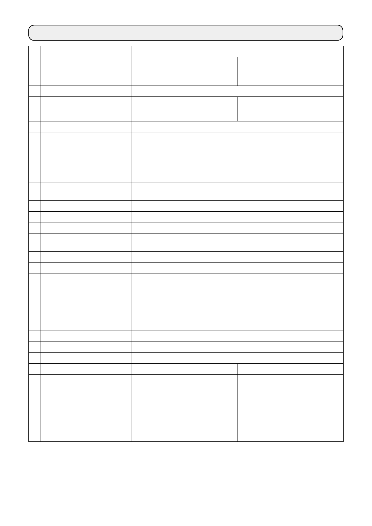
2-1. Installation of the sewing machine
1) To prevent possible accidents caused by the full
of the sewing machine, perform the work by two
persons or more when the machine is moved.
Do not hold the pulley and the reverse feed
lever.
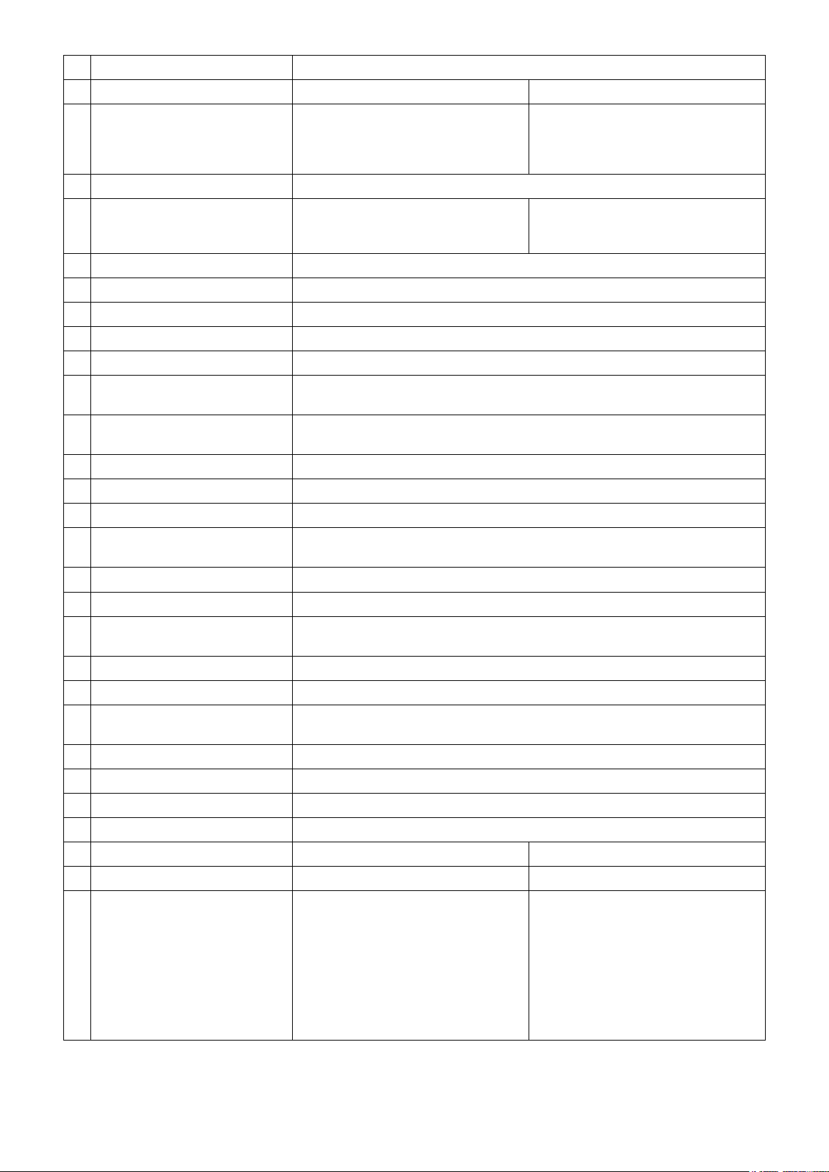
2) Do not put protruding articles such as the
screwdriver and the like at the location where
the sewing machine is placed.
❸
❷
Sheet B
❺
Sheet C
❹
❶
Sheet A
❹
25 mm
❺
❺
❸
19 mm
3) Attaching the hinge seats and the support rubbers of the machine head
Place sheets A and B (standard: three pieces)
and C (standard: one piece) between hinge seat
and machine head support rubbers ❷ and ❸.
❶
Then, x them on the table with nail.
Use nail ❺ for sheet C. Use nail ❹ for other
sheets.
There are two different machine head support
rubbers ❸; i.e., the rubber for the right and that
for the left. Be sure to check the types of the
support rubbers before xing them.
Sheets A and B (eight pieces each) and
sheets C (four pieces) are supplied with the
machine as accessories.
For the sheets A and B, three sheets are
to be used as standard for each mounting
position. For the sheet C, one sheet is to be
used as standard. (The state shown in the
left gure)
The sheets A, B and C are used for adjusting the height of the top surface of the bed.
Use one more sheet to increase the height,
or use only one sheet to decrease it.
– 4 –
Be sure to use a short nail ❺ for sheet C. If
long nail ❹ is used, the nail tip can penetrate the table giving rise to a risk of injury.
Page 7
Operator’s side
❺
Align
Table
Align
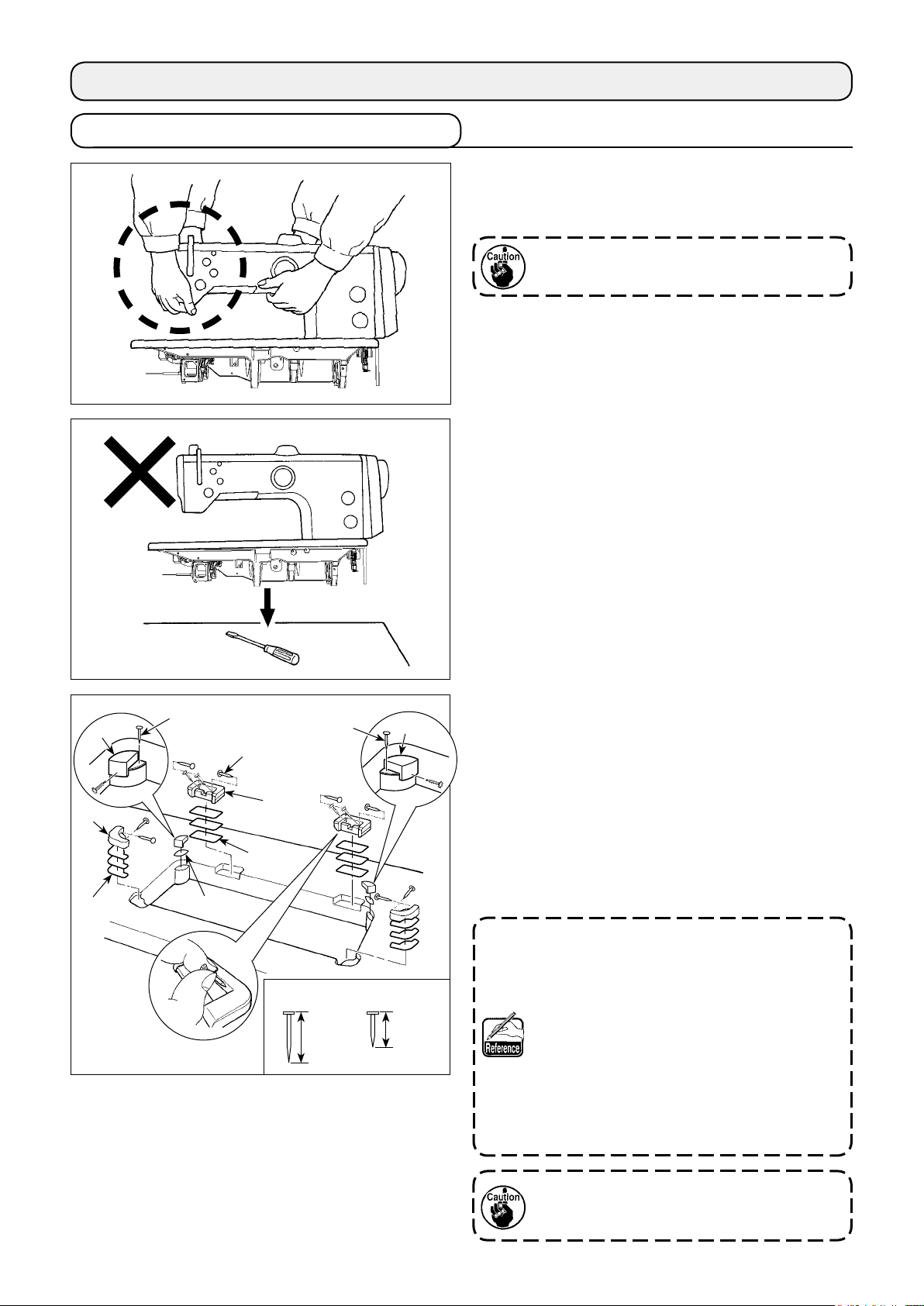
4) Attaching the oil pan
Fix the oil pan ❺ supplied with the machine on
the table by tightening ten wood screws.
Top surface
Multi-layered part
❻
5) Attach a lter ❻ to the oil pan ❺ as shown in
the gure.
Install lter ❻ so that its multi-layered part is
brought to the right side as observed from you.
❼
❺
6) Install hinge ❼ on the bed with screw ❽. En-
gage the hinge with the rubber hinge of the
table. Then, place the machine head on the
machine head support rubber.
❽
– 5 –
Page 8
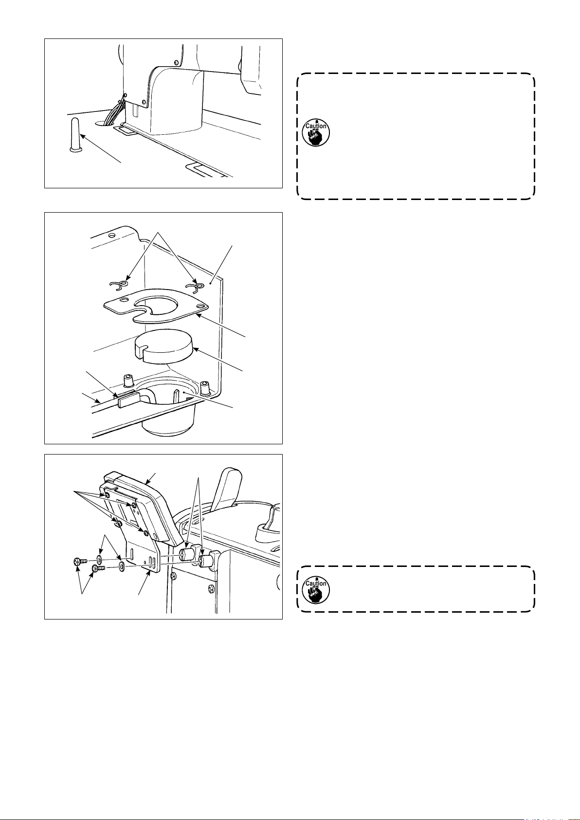
❾
❺
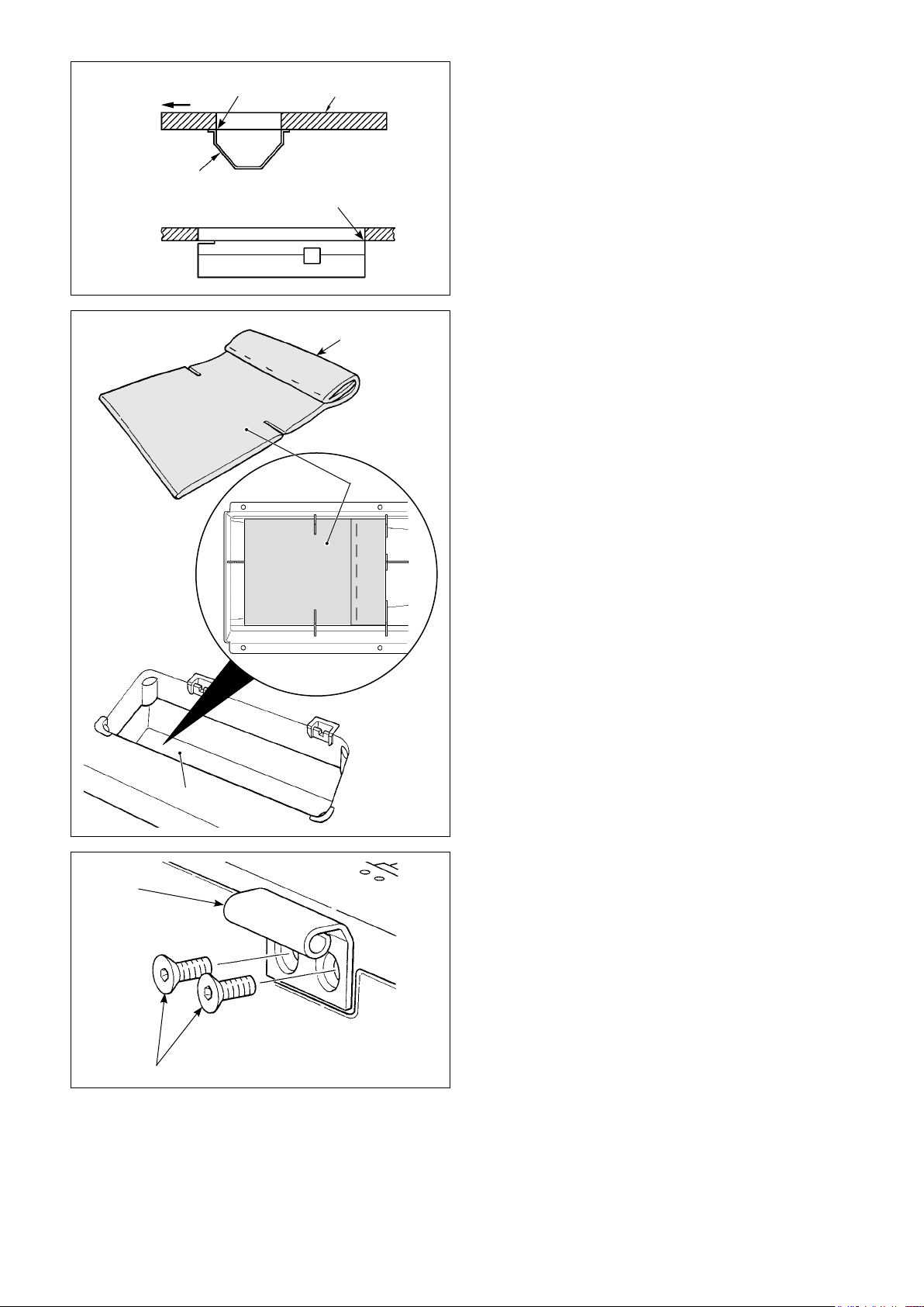
7) Securely attach head support rod ❾ until its rib
is closely pressed against the table.
When it is really necessary to conduct work
with the machine head supporting rod removed for the purpose of maintenance and
repair, it is necessary to carry out the work
with two or more persons.
In the case the machine head is tilted more
than necessary, oil can leak from the oil inlet of the oil tank. It is, therefore, necessary
to remove oil from the oil tank before tilting
the machine head.
8) Put reux pipe in the oil reservoir A of oil
pan ❺. Secure the pipe in groove .
9) Fix lter and lter clamp with tting .
A
10) Mount spacers supplied with the machine
head on the frame.
11) Install bracket on CP panel with screws
supplied with the panel.
12) Install bracket on spacer with screws
supplied with the machine head and washers
supplied with the panel.
Do not use the screws supplied the panel
instead of screws supplied with the machine head.
* Accessory screw supplied with the machine
head: Thread diameter M5; Length: 8 mm
– 6 –
Page 9
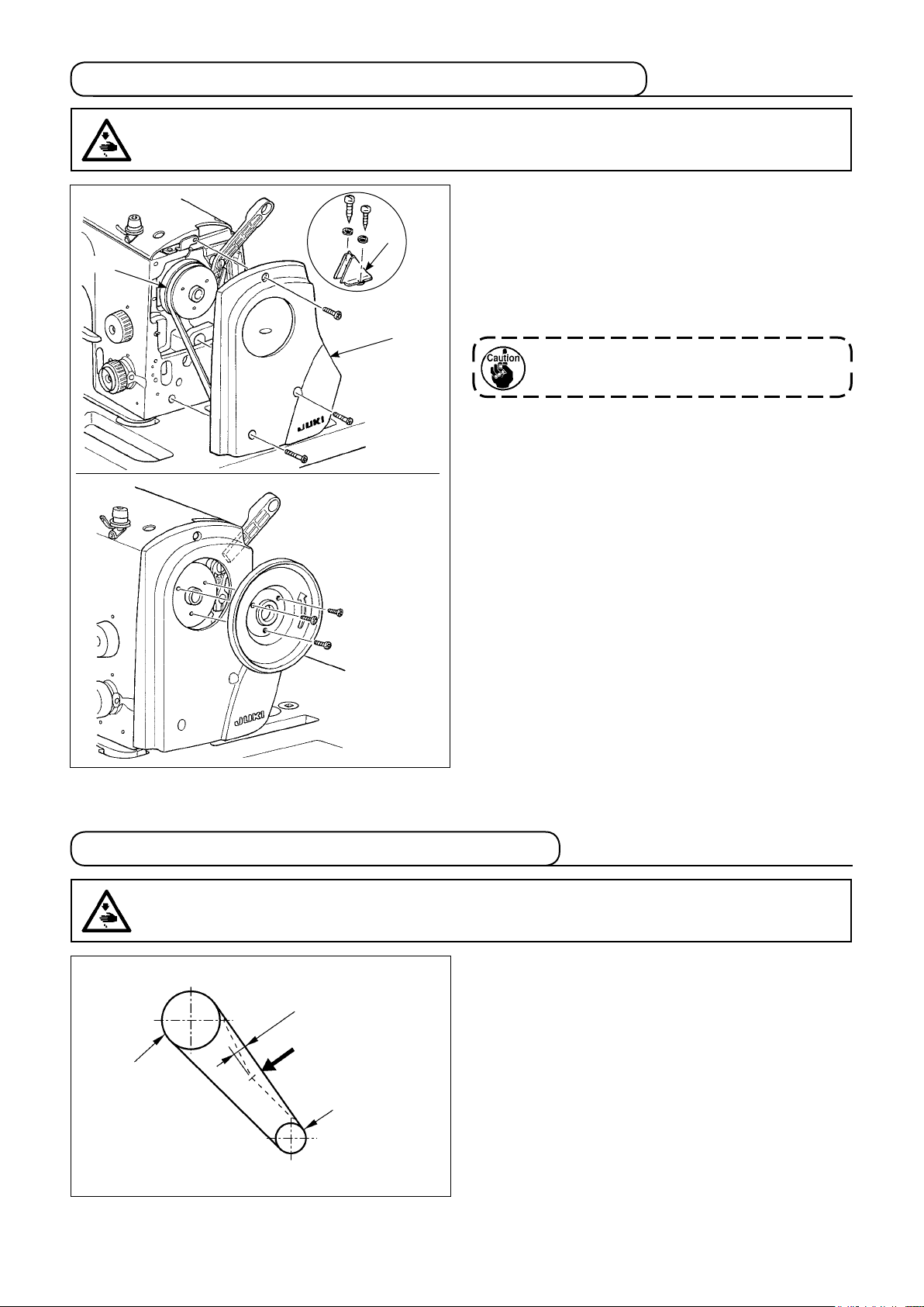
2-2. Installing the belt cover and the belt (LU-2810, LU-2860)
WARNING :
To protect against possible personal injury due to abrupt start of the machine, be sure to start the
following work after turning the power off and ascertaining that the motor is at rest.
(Installation procedure)
1) Put the V-belt on the sewing machine pulley.
❷
V-belt
❶
2) Install belt cover ❶ on the machine arm.
3) Install belt cover B ❷ on the table.
4) Mount the handle section of the pulley with a
screw.
When the sewing machine is used, covers
and ❷ must be installed without fail.
❶
2-3. Adjusting the belt tension (LU-2810, LU-2860)
WARNING :
To protect against possible personal injury due to abrupt start of the machine, be sure to start the
following work after turning the power off and ascertaining that the motor is at rest.
Adjust the belt tension with the height of the motor
so that the belt sags 15 mm when the center of V
15mm
9.8N
Handwheel
Motor pulley
belt is applied with a 9.8 N load.
– 7 –
Page 10
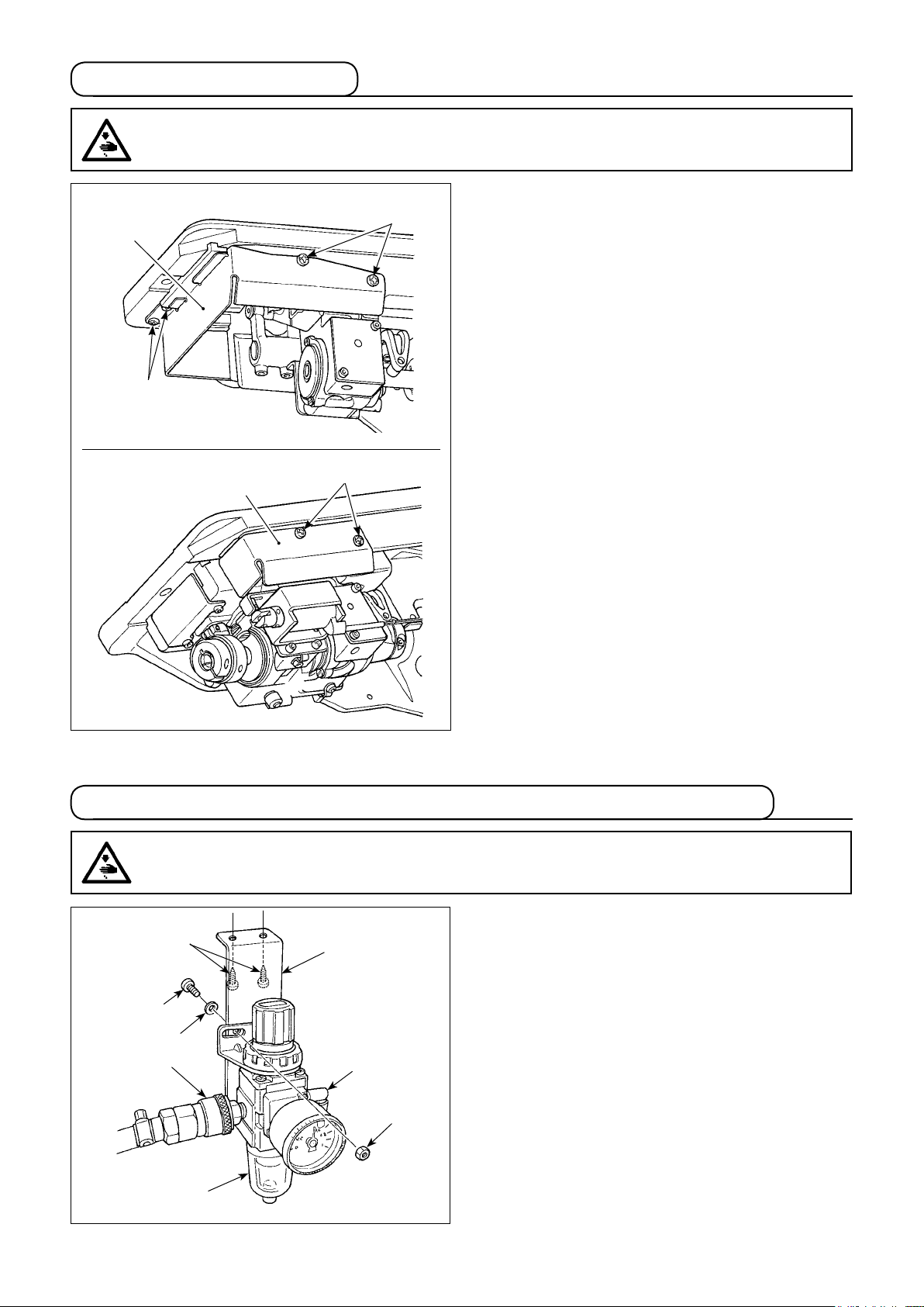
2-4. Installing the oil shield
WARNING :
To protect against possible personal injury due to abrupt start of the machine, be sure to start the
following work after turning the power off and ascertaining that the motor is at rest.
LU-2810, LU-2810-7, LU-2818-7
❶
❷
LU-2860, LU-2860-7, LU-2868-7
❶
❷
❷
Install oil shield ❶, supplied with the unit, on the
frame with screws ❷.
2-5. Pneumatic components (LU-2810-7, LU-2860-7, LU-2818-7, LU-2868-7)
WARNING :
To protect against possible personal injury due to abrupt start of the machine, be sure to start the
following work after turning the power off and ascertaining that the motor is at rest.
(1) Installing the regulator
❷
❼
❸
❽
❺
❻
❹
❶
1) Install regulator (asm.) ❶ on mounting plate
with screw ❷, spring washer ❸ and nut ❹
❺
which are supplied with the unit.
2) Install couplings ❻ and ❼ on regulator ❶.
3) Attach mounting plate ❺ on the undersurface of
the table with accessory screws ❽ supplied with
the plate.
4) Connect ø6 air tube coming from the sewing
machine to coupling ❻.
– 8 –
Page 11
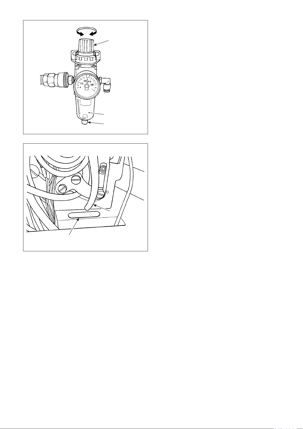
Decrease Increase
❶
A
❷
(2) Adjusting the air pressure
1) The operating air pressure is 0.5 to 0.55 MPa.
Adjust the air pressure using air pressure regu-
lating knob ❶ of the lter regulator.
2) In the case uid accumulation is observed in A
section of the lter regulator, turn drain cock ❷
to drain the uid.
(3) Exhaust tube
Pass ø8 exhaust tube ❶ coming from the sew-
ing machine through hole ❷ in the table.
In the case of high humidity, water may ow out
from the exhaust tube.
❷
❶
– 9 –
Page 12
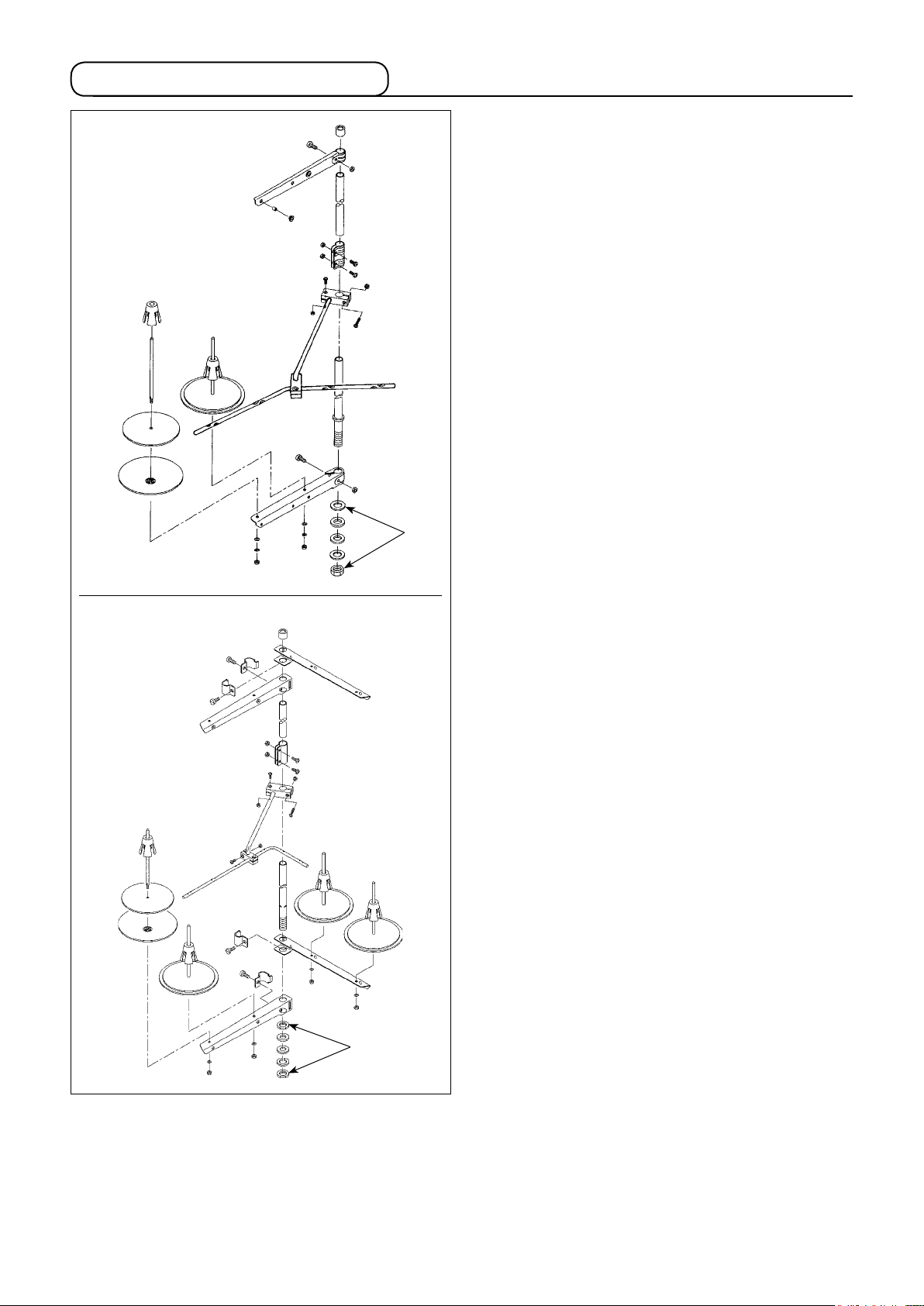
2-6. Installing the thread stand
LU-2810, LU-2810-7,
LU-2818-7
Assemble the thread stand, set it up on the machine
table using the installation hole in the table and tight-
en nut ❶ gently.
❶
LU-2860, LU-2860-7,
LU-2868-7
❶
– 10 –
Page 13
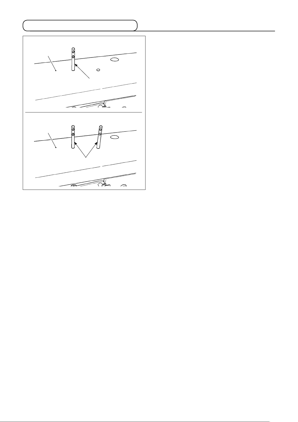
2-7. Installing the thread guide pin
LU-2810, LU-2810-7, LU-2818-7
❷
LU-2860, LU-2860-7, LU-2868-7
❷
❶
❶
Insert needle thread guide pin ❶ into the corresponding hole in top cover ❷.
LU-2810, LU-2810-7, LU-2818-7:
・
One needle thread guide pin
LU-2860, LU-2860-7, LU-2868-7:
・
Two needle thread guide pins
– 11 –
Page 14
3. PREPARATION OF THE SEWING MACHINE
3-1. Lubrication
WARNING :
1. Do not connect the power plug until the lubrication has been completed so as to prevent accidents
due to abrupt start of the sewing machine.
2. To prevent the occurrence of an inammation or rash, immediately wash the related portions if oil
adheres to your eyes or other parts of your body.
3. If oil is mistakenly swallowed, diarrhea or vomitting may occur. Put oil in a place where children
cannot reach.
LU-2810, LU-2810-7
LU-2860, LU-2860-7
❶
LU-2818-7, LU-2868-7
C
C
❷
A
B
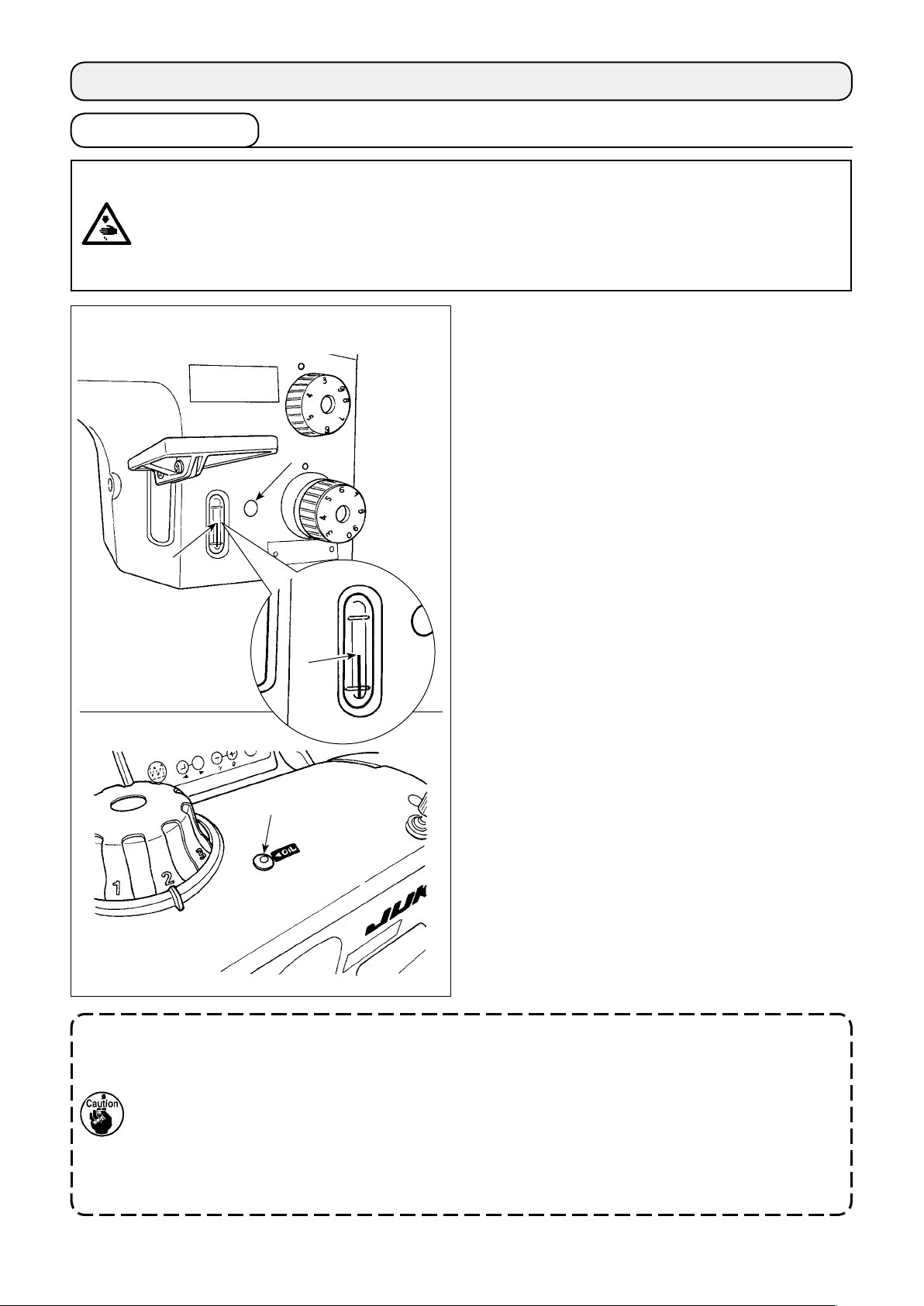
■ Lubrication procedure
Fill the oil tank with oil before operating the sewing
machine.
1) Fill the oil tank with JUKI NEW DEFRIX OIL
No.1 (Part No. : MDFRX1600C0) or JUKI MA-
CHINE OIL #7 (Part No. : MML007600CA) using
the oiler supplied with the machine from section
.
C
2) Fill the oil tank with the oil until the top end of
oil amount indicating rod ❷ comes between the
upper engraved marker line A and the lower
engraved marker line B of oil amount indicating
window ❶.
If the oil is lled excessively, it will leak from the
air vent hole in the oil tank or proper lubrication
will be not performed. In addition, when the oil
is vigorously lled, it may overow from the oil
hole. So, be careful.
3) When you operate the sewing machine, rell
oil if the top end of oil amount indicating rod ❷
comes down to the lower engraved marker line
of oil amount indicating window ❶.
B
1. When using a new sewing machine for the rst time or using the sewing machine which has not
been used for a long time, run in the sewing machine at a sewing speed of 1,000 sti/min or less and
check the oil quantity in the hook before use.
If the quantity of oil in the hook is insufcient, adjust the quantity of oil by turning the oil quantity
adjusting screw counterclockwise to ensure that the oil quantity in the hook is adequate. After that,
adjust the quantity of oil to the adequate one. (Refer to "■ Adjusting the oil quantity in the hook" p.13.)
2. For the oil for hook lubrication, purchase JUKI NEW DEFRIX OIL No. 1 (Part No. : MDFRX1600C0) or
JUKI MACHINE OIL #7 (Part No. : MML007600CA).
3. Be sure to lubricate clean oil.
– 12 –
Page 15
❷
❸
❶
❺
❹
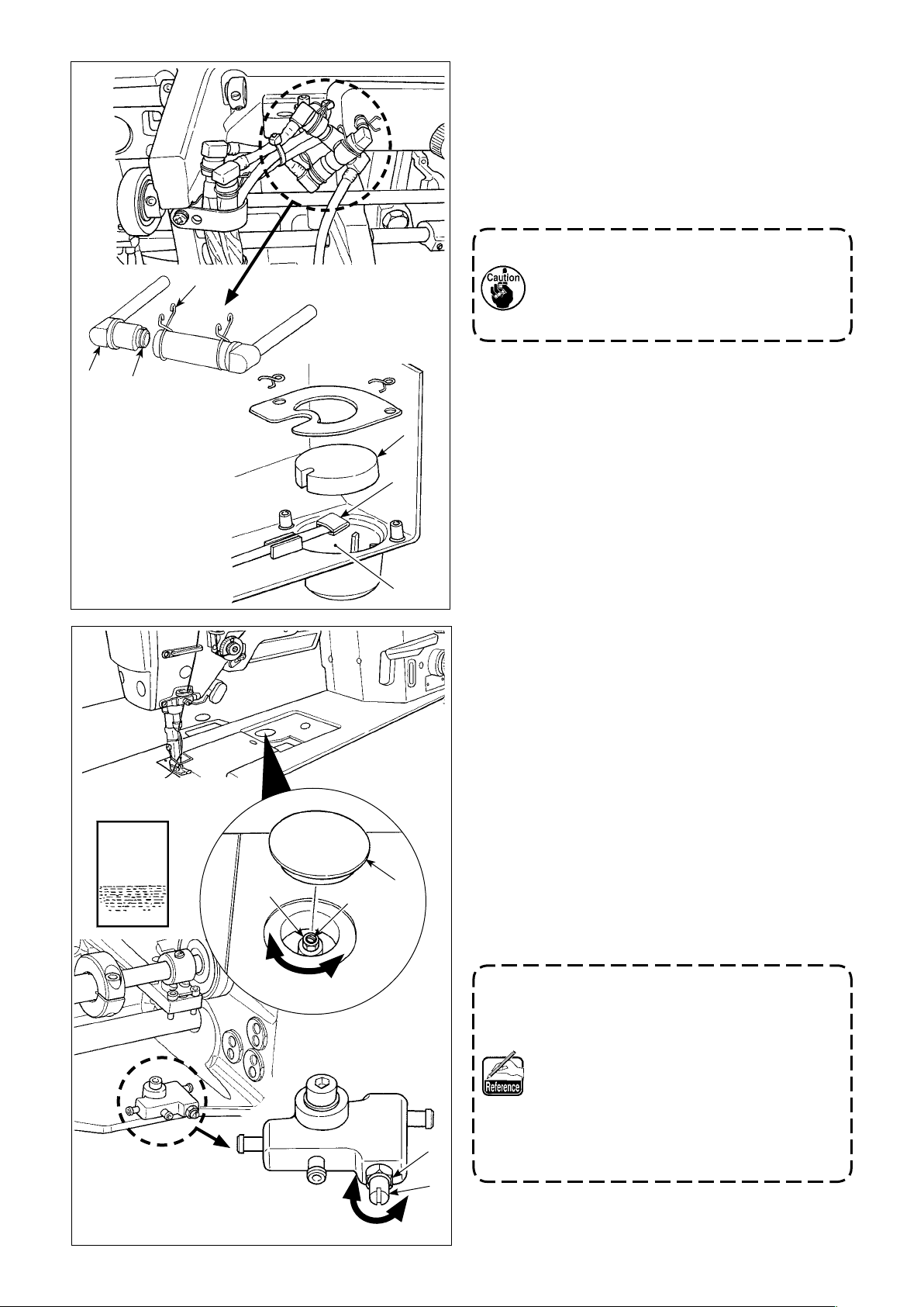
■ Cleaning the oil lter
1) Loosen fastening plate ❶ on the back-ow side.
Remove oil lter joint (asm.) ❷ on the back-ow
side.
2) Clean up lters ❸, ❹ and ❺ and oil reservoir
of the oil pan.
❻
Be sure to clean up the oil reservoir of the
oil pan and the lter case approximately
once a month.
If the lter is clogged with soil, lubrication
fails resulting in trouble.
A sheet of
paper
❻
■ Adjusting the oil quantity in the hook
LU-2810, LU-2810-7, LU-2818-7
1) Remove rubber cap❶.
2) Loosen nut ❷ and turn oil amount adjustment
screw ❸ to adjust the amount of oil in the hook.
Turning the screw clockwise A will decrease the
amount of oil in the hook or counterclockwise B
will increase it.
3) The appropriate amount of oil, when a sheet of
paper is placed near the periphery of the hook,
❷
❸
❶
is to such an extent that splashes of oil from the
hook appear in approximately ve seconds as
A
B
❹
shown in the gure on the left.
In the case the oil quantity in the hook cannot be adjusted to the proper quantity, it
should be adjusted by loosening nut ❹ and
turning oil quantity adjusting screw ❺. The
oil quantity in the hook is increased by turning the oil quantity adjusting screw counterclockwise C, or is decreased by turning it
clockwise D.
Also check to be sure that the oil is fed to the
hook at the sewing speed of 1,000 sti/min.
❺
D
C
– 13 –
Page 16

❶
A sheet of
paper
LU-2860, LU-2860-7, LU-2868-7
❷
1) Adjust distribution board ❶ to adjust
the oil quantity in the left hook or distribution board ❷ to adjust the oil quantity in the right hook as described below.
2) Loosen nut ❸ and turn oil amount adjustment screw ❹ to adjust the amount
of oil in the hook.
Turning the screw clockwise A will de-
crease the amount of oil in the hook or
counterclockwise B will increase it.
3) The appropriate amount of oil, when a
❸
sheet of paper is placed near the periphery of the hook, is to such an extent
that splashes of oil from the hook ap-
❹
A
pear in approximately ve seconds as
shown in the gure on the left.
3-2. Attaching the needle
WARNING :
To protect against possible personal injury due to abrupt start of the machine, be sure to start the
following work after turning the power off and ascertaining that the motor is at rest.
LU-2810, LU-2810-7, LU-2818-7
❷
❶
Long groove
LU-2860, LU-2860-7, LU-2868-7
B
❺
❻
D
C
In the case the oil quantity in the
hook cannot be adjusted to the
proper quantity, it should be adjusted by loosening nut ❺ and
turning oil quantity adjusting
screw ❻. The oil quantity in the
hook is increased by turning the
oil quantity adjusting screw counterclockwise C, or is decreased by
turning it clockwise D.
Also check to be sure that the oil
is fed to the hook at the sewing
speed of 1,000 sti/min.
Switch "off" the motor.
Use 135x17 needles.
1) Turn the handwheel to bring the needle bar to
the highest position of its stroke.
2) Loosen needle clamp screw ❷. Hold the needle so that the long groove on needle ❶ faces
directly to the right for the LU-2810, 2810-7 and
2818-7, and so that the long groove on each the
two needles faces inward for the LU-2860, 28607 and 2868-7.
3) Push needle ❶ deep into the needle clamp hole
until it will go no further.
4) Tighten needle clamp screw ❷ rmly.
❷
❶
❶
❷
Long groove
When replacing the needle, check the clearance provided between the needle and the
blade point of hook. (Refer to "4-5. Needle-
to-hook relation" p.27 and "4-6. Adjusting
the hook needle guard" p.28.)
If there is no clearance, the needle and the
hook will be damaged.
– 14 –
Page 17

3-3. Attaching and removing the bobbin
WARNING :
To protect against possible personal injury due to abrupt start of the machine, be sure to start the
following work after turning the power off and ascertaining that the motor is at rest.
1) Lift latch ❶ of hook, and take out the bobbin.
2) Put the bobbin into the shaft in the hook correct-
ly and release the latch.
1. Do not make the machine run idle with
the bobbin (bobbin thread). The bobbin
thread is caught in the hook. As a result,
the hook may be damaged.
2. Be careful so as not to get hurt with the
top end of the counter knife.
❶
3-4. Threading the hook
WARNING :
To protect against possible personal injury due to abrupt start of the machine, be sure to start the
following work after turning the power off and ascertaining that the motor is at rest.
LU-2810, LU-2860
❷
❶
LU-2810-7, LU-2860-7, LU-2818-7, LU-2868-7
1) Pass the thread through thread path ❶ in the
inner hook and between ❷ the opener and in-
ner hook, and slowly draw the thread. Now, the
thread passes under the tension spring.
2) Make sure that the bobbin revolves in the direc-
tion of the arrow when you draw the thread.
1) Pass the thread through thread path ❶ in the
inner hook and thread hole ❷ in the lever, and
slowly draw the thread. Now, the thread passes
under the tension spring.
2) Make sure that the bobbin revolves in the direc-
tion of the arrow when you draw the thread.
❷
❶
– 15 –
Page 18

3-5. Winding a bobbin
❻
❼
❹
❸
❶
❷
1) Pass the thread through sections ❶ to ❹ in the
numerical order.
2) Put the thread until the root of bobbin thread
clamp ❺ is reached. Then, trim the thread. (The
thread end is retained under the looper thread
clamp.)
3) Load a bobbin on bobbin winder shaft ❻.
4) Press bobbin winder lever ❼ in the direction of
the arrow.
5) When you start the sewing machine, the bobbin
rotates to automatically wind the thread on itself.
6) When the bobbin is lled up, the bobbin winder
lever automatically releases the bobbin and the
bobbin winder stops running.
1. The bobbin thread winding amount is ad-
justed by loosening setscrew ❽. The bobbin thread winding amount is increased
by moving bobbin wider lever ❼ upward.
2. If the thread comes off the thread tension
controller, wind the thread on the intermediate thread guide by one turn.
❽
❺
1. This is the one-touch type bobbin wind-
er. When the bobbin is fully wound with
thread, bobbin thread clamp ❺ automatically returns to the initial position.
2. To terminate bobbin winding before the
bobbin is fully wound with thread, turn the
handwheel, while slightly lifting bobbin
winder lever ❼, to bring bobbin thread
clamp ❺ back to its initial position.
3. If the thread is not brought to the root of
the bobbin thread clamp, the thread slips
off the bobbin at the beginning of bobbin
winding.
– 16 –
Page 19

3-6. Threading the machine head
[LU-2810, 2810-7, 2818-7]
WARNING :
To protect against possible personal injury due to abrupt start of the machine, be sure to start the
following work after turning the power off and ascertaining that the motor is at rest.
❷
❶
❾
❽
❼
❸
❹
❺
❻
❸
❹
❺
❻
❼
Thread the machine head following the order
as illustrated in the gure.
* Pass thread through the right side of
thread guide .
LU-2810-7
LU-2818-7
1. Thread guide is necessary to prevent the thread from slipping off the needle eyelet when performing thread trimming at a position which is outside the material.
2. If thread tangling failure occurs when starting sewing from the material edge, the thread should be
removed from the location where it is clamped with the spring of thread guide , or thread guide
should be changed with another one. The replacement thread guide is separately available.
Part number of replacement thread guide: 40084142
LU-2810
– 17 –
Page 20

[LU-2860, 2860-7, 2868-7]
WARNING :
To protect against possible personal injury due to abrupt start of the machine, be sure to start the
following work after turning the power off and ascertaining that the motor is at rest.
Left-hand
needle thread
Right-hand
needle thread
❾
❷
❽
❼
❻
❸
❺
❹
❺
❻
❶
❹
❸
❶
❸
❹
❺
❻
❼
Thread the machine head following the
LU-2860-7
LU-2868-7
1. Thread guide is necessary to prevent the thread from slipping off the needle eyelet when performing thread trimming at a position which is outside the material.
2. If thread tangling failure occurs when starting sewing from the material edge, the thread should be
removed from the location where it is clamped with the spring of thread guide , or thread guide
should be changed with another one. The replacement thread guide is separately available.
Part number of replacement thread guide: 40084142
LU-2860
order as illustrated in the gure.
– 18 –
Page 21

3-7. How to set the model of the machine head
CP-18
•
1) Call Function Setting No. 95 in refer-
ence to
"III-6. Function Setting of
SC-922" in the Instruction Manual
for the SC-922
.
❺❹❸
❻
2) The type of machine head can be se-
lected by pressing
switch ❺ (
switch ❻).
Select the model of the machine head
according to the table shown below.
Model Indication
LU-2810 LU81
LU-2860 LU86
❺❹❸
❻
LU-2810-7 L81d
LU-2860-7 L86d
LU-2818-7 L81L
LU-2868-7 L86L
3) After selecting the type of machine
head, by pressing switch ❸ (
switch ❹), the step proceeds to 94
or 96, and the display automatically
changes to the contents of the setting
corresponding with the type of ma-
chine head.
❺❹❸
❻
4) Turn the power OFF.
– 19 –
Page 22

CP-180
•
❶
1) Refer to
in the Instruction Manual for the CP-180
"18. FUNCTION SETTING SWITCH"
, and
call the function setting No. 95.
2) The type of machine head can be selected by
pressing switch ❶.
Select the model of the machine head accord-
ing to the table shown below.
Model Indication
LU-2810 LU81
LU-2860 LU86
LU-2810-7 L81d
LU-2860-7 L86d
LU-2818-7 L81L
LU-2868-7 L86L
3) After selecting the type of machine head, by
pressing switch ❷, the step proceeds to 96 or
94, and the display automatically initializes to
the contents of the setting corresponding with
the type of machine head.
❷
4) Turn the power OFF.
– 20 –
Page 23

CP-18
•
3-8.
Adjusting the machine head (LU-2810-7, LU-2860-7, LU-2818-7, LU-2868-7)
A
1) Simultaneously pressing switch
❸
❹
and
switch ❺, turn ON the
power switch.
2) is displayed A in the indicator
and the mode is changed over to the
adjustment mode.
❺❹
❻
B
3) Turn the pulley of the machine head by
hand until the main-shaft reference sig-
nal is detected. At this time, the degree
of an angle from the main-shaft refer-
ence signal is displayed on the indicator
.
B
(The value is the reference value.)
❺❹❸
❻
❽
4) In this state, align one of the marker
dots ❼ on the pulley with marker line
on the pulley cover as shown in the
❽
❼
gure.
5) Press switch ❻ to nish the adjust-
ment work. (The value is the reference
value.)
6) Turn the power OFF.
❺❹❸
❻
When checking the adjustment result, set "Function setting No. 90; Initial sewing machine movement
function" at "1: Initial operation - Sewing machine stops with its needle up". Then, check whether or not
marker dot ❼ is aligned with marker line ❽. If they are not aligned, carry out the adjustment again.
After checking the adjustment result, return the setting of No. 90 to the previous setting. (Initial value is
"2. Initial operation: Sewing machine turns in the reverse direction and stop with its needle up".)
For the function setting procedure, refer to "III-6. How to set the functions of the SC-922" in the Instruction Manual for the SC-922.
– 21 –
Page 24

CP-180
•
1) Simultaneously pressing switch ❶ and switch
, turn ON the power switch.
❷
❷❶
❽
2)
BA
is displayed A in the indicator and the
mode is changed over to the adjustment mode.
3) Turn the pulley of the machine head by hand
until the main-shaft reference signal is detected.
At this time, the degree of an angle from the
main-shaft reference signal is displayed on the
indicator B.
(The value is the reference value.)
4) In this state, align one of the marker dots ❼ on
the pulley with marker line ❽ on the pulley cov-
er as shown in the gure.
❼
❹
5) Press switch ❹ to nish the adjustment work.
(The value is the reference value.)
6) Turn the power OFF.
When checking the adjustment result, set
"Function setting No. 90; Initial sewing machine movement function" at "1: Initial operation - Sewing machine stops with its needle
up". Then, check whether or not marker dot
is aligned with marker line ❽. If they are
❼
not aligned, carry out the adjustment again.
After checking the adjustment result, return
the setting of No. 90 to the previous setting.
(Initial value is "2. Initial operation: Sewing
machine turns in the reverse direction and
stop with its needle up".)
For the function setting procedure, refer to
"18. How to set the functions" in the Instruction Manual for the CP-180.
– 22 –
Page 25

4. ADJUSTING THE SEWING MACHINE
4-1. Adjusting the stitch length
Turn standard feed adjusting dial ❶ and 2P feed ad-
❸
❹
❷
❸
❶
justing dial ❷ to align the desired number with mark-
er dot ❸ on the machine dial.
(1) Reverse feed stitching
1) Press down reverse feed control lever ❹.
2) Reverse feed stitches are made as long as you
keep pressing the lever down.
3) Release the lever, and the machine will run in
the normal feed direction.
(2) Manual one-touch reverse feed stitching
1) Press touch-back switch ❺.
2) Reverse feed stitches are made as long as you
keep pressing the lever down.
3) Release the switch, and the machine will run in
the normal feed direction.
❻
❺
(3) Changing over the stitching pitch (LU-2810-7,
2860-7, 2818-7 and 2868-7)
1) Press stitching pitch changeover switch ❻ to
change over the stitch length to the one cor-
responding to the scale mark on the 2P feed ad-
justing dial. (The LED on the switch lights up.)
1. Set 2P feed adjusting dial ❷ at a value
smaller than the value set by standard
feed adjusting dial
2. Adjust the 2P feed adjusting dial when
the stitching pitch changeover switch is
placed in OFF.
3. (LU-2810-7, LU-2860-7)
Scale mark on the 2P feed adjusting
dial smaller than 3 (at which the dial is
stopped by the dial stopper) is used for
the 0 (zero) alignment of the 2P dial. Scale
marks smaller than 3 cannot be used.
4. (LU-2818-7, LU-2868-7)
In the case standard stitch dial ❶ is set
at a small pitch value, move feed control
lever ❹ up and down several times before
starting sewing.
.
❶
– 23 –
Refer to "5-7. Operation switches (LU-2810-
7, LU-2860-7, LU-2818-7, LU-2868-7)" p.39
for the details of the 2P device.
Page 26

4-2. Thread tension
(1) Adjusting the needle thread tension
B A
1) Turn thread tension nut No. 1 ❶ clockwise A to
C
D
❶
❷
shorten the length of thread remaining on the
top of needle after thread trimming. Turn the nut
counterclockwise B to lengthen it.
2) Turn thread tension nut No. 2 ❷ clockwise C to
increase the needle thread tension, or counter-
clockwise D to decrease it.
Apply the same tension to both of the
thread tension nut No. 2.
In the case, the length of thread remaining
at the needle tip cannot be increased, re-
place the spring of tension controller No. 1
with 22945505 which is separately available.
WARNING :
To protect against possible personal injury due to abrupt start of the machine, be sure to start the
following work after turning the power off and ascertaining that the motor is at rest.
(2) Adjusting the bobbin thread tension
Turn tension adjustment screw ❸ clockwise A to
increase the bobbin thread tension, or counterclock-
wise B to decrease it.
A
❸
B
– 24 –
Page 27

4-3. Thread take-up spring
❹
❶
❷
❸
❺
(1) When you want to change the stroke of the
thread take-up spring
1) Loosen screw ❷. Adjust thread take-up spring
by moving it in the slot.
❶
2) Loosen screw ❹. Adjust thread take-up spring
by moving thread take-up spring adjusting
❸
plate ❺ along thread take-up spring base ❻.
* The LU-2810, 2810-7 and 2818-7 do not have
thread take-up spring ❸.
❶
❸
❾
❽
❼
❻
(2) When you want to change the tension of
the thread take-up spring
1) To adjust the tension of thread take-up spring ❶,
loosen nut ❼ rst. Turn spring shaft ❽ counter-
clockwise to increase the tension or clockwise
to decrease it.
After the adjustment, x the stud by tightening
nut ❼.
2) To change the tension of thread take-up spring
, loosen screw ❾ rst. Turn nut counter-
❸
clockwise to increase the tension or clockwise
to decrease it.
After the adjustment, x nut by tightening screw
.
❾
Decrease
* The LU-2810, 2810-7 and 2818-7 do not have
thread take-up spring ❸.
Increase
– 25 –
Page 28

4-4. Adjusting the pressure of the presser foot
Turn presser spring regulating dial ❶ clockwise A to
B
A
increase the pressure of the presser foot, or counter-
clockwise B to decrease it.
A
❶
Be sure to operate the sewing machine with
the pressure of the presser foot minimized
as long as the presser foot securely holds
the material.
The adjustable range extends from 38 mm to 60 mm
which represents the distance from the upper sur-
face A of the arm to presser spring regulating dial ❶.
The standard value at the time of shipment is 47
mm.
– 26 –
Page 29

4-5. Needle-to-hook relation
WARNING :
To protect against possible personal injury due to abrupt start of the machine, be sure to start the
following work after turning the power off and ascertaining that the motor is at rest.
1.5 mm
Hook driving shaft
setting collar
Hook driving shaft D
❷
❶
2.3 mm
0.05 to 0.1 mm
Hook driving shaft C
Hook driving shaft
setting collar
❸
❹
❺
The hook driving shaft
setting collar is aligned
with the end face of hook driving shaft D
❸
Left hook
Right hook
1) Adjust the standard feed adjusting dial to "0".
The hook driving shaft setting
collar is aligned with the end
face of hook driving shaft C
(Caution 1)
2) Loosen hook driving shaft set collar clamping screw ❸, and turn the handwheel counterclockwise to
make the needle bar ascend by 2.3 mm from the lowest position of its stroke.
3) In the state described in 2), align blade point ❶ of the hook with the center of needle ❷, and tighten
hook driving shaft set collar clamping screw ❸. At this time, a clearance of 1.5 mm is provided between the blade point of the hook and the top end of the needle eyelet. (The hook driving shaft set collar
should be ush with end faces C and D of the hook driving shaft.)
4) Loosen setscrews ❹ and ❺ of the hook driving shaft saddle on the top face of the bed. Adjust the clearance between the blade point of the hook and the needle to 0.05 to 0.1 mm by moving the hook driving
shaft saddle to the right or left to change its position. Then, tighten setscrews ❹ and ❺.
5) Align the largest scale mark of the standard feed adjusting dial with the marker dot on the machine arm.
Check to be sure that the blade point of the hook does not come in contact with the needle.
2. The operation panel could come in contact with the thread stand when tilting the machine head.
1. If stitch skipping and thread breakage occur when using elastic thread such as vinylon, adjust the
hook timing with the pitch used for sewing.
To protect the relevant parts from contact, shift the thread stand to a position at which the thread
stand does not interfere with the control panel.
[Only for the LU-2810-7, LU-2860-7, LU-2818-7 and LU-2868-7]
To check the needle bar position as described in the aforementioned 2) [i.e., "...the needle bar ascend
by 2.3 mm from the lowest position of its stroke"], you may use the display of the main shaft rotation
angel under the "machine head adjustment mode" of the SC-922.
Increase the numerical value displayed when the needle bar is in its lowest position of its stroke under
the "machine head adjustment mode" by 25 degrees of an angle, the needle bar goes up by 2.3 mm.
(When the needle bar ascends by 2.3 mm from its lowest position of its stroke, the main shaft rotation
angle is 25 degrees of an angle.)
* In the case of adjusting the needle-to-hook relation under the "machine head adjustment mode", do
not press switch. Refer to "II-10. Adjustment of the machine head" in the Instruction Manual for
the SC-922 for the machine head adjustment mode.
– 27 –
Page 30

4-6. Adjusting the hook needle guard
WARNING :
To protect against possible personal injury due to abrupt start of the machine, be sure to start the
following work after turning the power off and ascertaining that the motor is at rest.
❹
❶
❷
0.05 to
0.2 mm
a
B
b
❸
When a hook has been replaced, be sure to check
the position of the hook needle guard.
As the standard position of the hook needle guard,
A
hook needle guard ❷ must push the side face of
needle ❶ to lean the needle by 0.05 to 0.2 mm away
from its straight position.
If the state of the hook is not as shown above, fit
hexagon wrench ❹ into ❸ of needle guard adjusting
screw and adjust as follows:
1) To bend the hook needle guard in direction a,
turn the needle guard adjusting screw in direc-
tion A.
2) To bend the hook needle guard in direction b,
turn the needle guard adjusting screw in direc-
tion B.
3) At the nal step of procedure, appropriately ad-
just the clearance provided between the needle
and the hook.
– 28 –
Page 31

4-7. Adjusting the bobbin case opening lever
WARNING :
To protect against possible personal injury due to abrupt start of the machine, be sure to start the
following work after turning the power off and ascertaining that the motor is at rest.
❸
❹
❶
LU-2810, 2810-7, 2818-7
0.7 to 0.9 mm
LU-2860, 2860-7, 2868-7
0.9 to 1.1 mm
❷
A
LU-2810, LU-2810-7
1) Turn the handwheel in the normal direction of
rotation to bring bobbin case opening lever ❶ to
the closest position to inner hook ❷.
2) Turn inner hook ❷ in the direction of the arrow
until stopper ❸ is pressed against the slits in
throat plate ❹.
3) Loosen opener crank setscrew ❺. Adjust the
clearance provided between the bobbin case
opening lever and protruding portion A of the
inner hook to 0.7 to 0.9 mm.
Tighten setscrew ❺ while pressing down bobbin
case opening lever crank ❻.
LU-2810, 2810-7
LU-2860, 2860-7, 2818-7, 2868-7
❻
❺
LU-2860, LU-2860-7, LU-2818-7, LU-2868-7
1) Turn the handwheel in the normal direction of
rotation to bring bobbin case opening lever ❶ to
the closest position to inner hook ❷.
2) Turn inner hook ❷ in the direction of the arrow
until stopper ❸ is pressed against the slits in
throat plate ❹.
3) Loosen setscrews ❼ of the bobbin case open-
ing lever sleeve. Adjust the clearance provided
between the bobbin case opening lever and
protruding portion A of the inner hook to 0.9 to
1.1 mm for the LU-2860, -2860-7 and 2868-7, or
to 0.7 to 0.9 mm for the LU-2818-7.
Tighten setscrews ❼ while pressing bobbin
case opening lever ❶ downward and pressing
the bobbin case holding lever sleeve ❽ upward.
❽
❼
– 29 –
Page 32

4-8. Adjusting the position of counter knife, knife pressure and clamp pressure
WARNING :
To protect against possible personal injury due to abrupt start of the machine, be sure to start the
following work after turning the power off and ascertaining that the motor is at rest.
LU-2810-7, LU-2860-7 LU-2818-7, LU-2868-7
3.7 ± 0.1 mm
❸
❼
❹
Strike
❶
3.7 ± 0.1 mm
❸
❼
Strike
❹
❶
37 ± 0.1 mm
34.5 ± 0.1 mm
❻
1.2 to 1.5 mm
Knife pressure starts to be developed
❻
❺
❷
LU-2810-7:
6 to 7 mm
LU-2860-7:
8 to 9 mm
1.2 to 1.5 mm
Knife pressure starts to be developed
❺
❷
8
to
9 mm
1) Move the moving knife ❺ by hand to its forward travel end.
• Adjusting the counter knife
2) Loosen counter knife base setscrews ❶. Adjust the position of the counter knife so that top end of the
counter knife ❸ so that it is spaced 1.2 to 1.5 mm from the end face of the throat plate in terms of the
lateral direction, and so that it is pressed against the stepped section of hook driving shaft saddle in
terms of the longitudinal direction. Then, tighten setscrews ❶.
Loosen counter knife setscrews ❼. Adjust the distance between the bed slide mounting plane and the
counter knife tip to 37 ± 0.1mm for the LU-2810-7 and LU-2860-7, or 34.5 ± 0.1 mm for the LU-2818-7
and LU-2868-7. Then, tighten setscrews ❼.
• Adjusting the knife pressure
3) Loosen setscrews ❷ in the moving knife.
Turn the handwheel to move the moving knife and adjust the knife pressure.
As the standard adjustment, the knife pressure should be applied from the time when the distance from
the top end of the moving knife to the top end of the counter knife is 6 to 7 mm for the LU-2810-7, or 8
to 9 mm for the LU-2860-7, -2818-7 and -2868-7.
1. Adjust the knife pressure in the state that the clamp spring ❹ does not come in contact with the
moving knife ❺ (the clamp pressure is not developed).
2. Be sure to carefully prevent from getting injured by the moving knife ❺, counter knife ❸, blade
point of the hook, etc.
• Adjusting the clamp pressure
4) To adjust the clamp pressure, rstly loosen clamp spring setscrew ❻. Adjust the lateral position of
clamp spring so that a clearance of 3.7 ± 0.1 mm is provided between clamp spring ❹ and counter knife
. Then, adjust the longitudinal position of the clamp spring by tightening setscrew ❻ with the clamp
❸
spring pressed against the stepped portion of the counter knife base.
Check to make sure that the clamp pressure is applied when moving knife ❺ moves to its back end.
– 30 –
Page 33

4-9. Adjusting the condensation stitch (LU-2818-7, LU-2868-7)
WARNING :
To protect against possible personal injury due to abrupt start of the machine, be sure to start the
following work after turning the power off and ascertaining that the motor is at rest.
1) Place stitch dial plate ❺ at the desired conden-
sation amount.
(Pitch 2 in the case of condensation amount of
2 mm)
❹
❷
❶
❸
Loosen condensation stitch arm bracket screw
.
❶
2) Push up condensation cylinder ❹ in the di-
rection of the arrow. At this time, push down
reverse feed control lever ❻ by hand to put the
sewing machine in the reverse feed stitching
state. In this state, tighten condensation crank
clamping screw ❶ at the position where the top
end of slot in link ❷ comes in contact with hinge
screw ❸.
❻
❺
Contact
If the condensation amount is excessively
small, the material can be torn depending
on the type of seam to cause stitch skipping. This can cause a thread trimming failure.
– 31 –
Page 34

4-10. Adjusting the amount of the alternating vertical movement of the walking
foot and the presser foot
Adjust the amount of the alternating vertical move-
ment of the walking foot and the presser foot us-
❶
❸
ing dial ❶. Turn the dial clockwise to increase the
amount of the alternating vertical movement of the
walking foot and the presser foot, or counterclock-
wise to decrease it.
Excluding the 1-needle European gauge type sew-
ing machine, the amount of the alternating vertical
movement of the walking foot and the presser foot
has been factory-limited to 6.5 mm at the time of
shipment.
To cancel the restriction to the amount of the alter-
nating vertical movement of the walking foot and the
presser foot, remove the top cover, loosen setscrews
and shift stopper ❸ to the right.
❷
To release the stopper by means of the
standard gauge, the presser foot may interfere with the walking foot. The presser foot
❷
may also interfere with the needle bar when
a heavy-weight material is used.
Make sure that the presser foot interferes
with neither the walking foot nor the presser
bar before operating the sewing machine.
5. OPERATION OF THE SEWING MACHINE
5-1. Hand lifter
To lift the presser foot manually, pull hand lifter ❶ in
the direction of the arrow.
This makes the presser foot rise 10 mm and stay at
❶
that position.
– 32 –
Page 35

5-2. Resetting the safety clutch
WARNING :
To protect against possible personal injury due to abrupt start of the machine, be sure to start the
following work after turning the power off and ascertaining that the motor is at rest.
The safety clutch functions when an excessive load
is applied to the hook or the other components dur-
❶
ing sewing. At this time, the hook will never rotate
even if turning the handwheel. When the safety
clutch has functioned, remove the cause and reset
the safety clutch as given in the following procedure.
1) Pressing push button ❶ located on the top
surface of the machine bed, strongly turn the
handwheel in the reverse direction of rotation.
2) The resetting procedure completes when the
handwheel clicks.
Turn the handwheel by hand, and confirm
that push button ❶ has returned.
3) At the nal step of procedure, check the needle-
to-hook relation. (Refer to
relation" p.27
)
"4-5. Needle-to-hook
– 33 –
Page 36

5-3. Adjusting the automatic presser foot lifter
WARNING :
To protect against possible personal injury due to abrupt start of the machine, be sure to start the
following work after turning the power off and ascertaining that the motor is at rest.
1) Turn the power ON. Carry out thread trimming
once. Turn ON the automatic presser lifter.
2) Place a 20 mm spacer ❶ under the presser
foot.
3) Turn the power OFF.
❶
4) Remove rubber cap ❷ from the rear face of the
machine arm. Loosen setscrew ❸.
5) Turn presser bar lifting arm ❹ in the direction of
the arrow until it will go no further. Then, tighten
setscrew ❸.
❷
❸
For the standard gauge type machine, the
top end of the walking foot interferes with
the needle bar frame when the auto-lifter is
used in the case the amount of the alternating vertical movement of the walking
foot and the presser foot is set at 2 mm or
smaller and in the case it is set at 7 mm or
more and the reverse-rotation needle-up is
carried out.
To use the machine with the amount of the
alternating vertical movement of the walking
foot and the presser foot set at 2 mm or less,
set the lifting amount of the presser foot by
means of the auto-lifter at 17 mm or less.
❹
– 34 –
Page 37

5-4. Fixing the feed adjusting dial
LU-2810, 2810-7, 2860, 2860-7
❷
LU-2810, 2810-7, 2860, 2860-7
❹
❸
❶
❺
If the feed adjusting dial moves out of the set po-
sition when the automatic reverse feed device is
operated (LU-2810, 2810-7, 2860, 2860-7):
1) Remove rubber cap ❶. Tighten screws ❷.
To prohibit the adjustment of the feed adjusting
dial (LU-2810, 2810-7, 2860, 2860-7):
1) Remove the motor cover or the belt cover.
2) Insert stopper pin ❺ and screw ❻ in tapped
hole ❸ (or holes ❸ and ❹ for the LU-2810-7
and -2860-7) and tighten it.
Insert stopper pin ❺ into the tapped hole from
its thinner end as illustrated in the gure.
❻
Stopper pin ❺ and screw ❻ are separately
available.
Part number of stopper pin : TA0440401MO
Part number of screw : SM8060612TP
– 35 –
Page 38

LU-2818-7, 2868-7
❷
❶
A
❹
❸
❺
To prohibit the adjustment of the feed adjusting
dial (LU-2818-7, 2868-7):
1) Loosen stitch dial setscrew ❸ (or ❹). Remove
stitch dial ❶ (or ❷) and four washers ❺.
2) Insert stitch dial ❶ (or ❷) back to its original
position and push it in direction A.
Notch ❻ of the dial ts on projecting sections ❼
of the cover to x the dial so that it will not turn
any further.
3) In the state as described in 2), tighten feed reg-
ulating dial setscrews ❸ (or ❹) alternately to
x dial ❶ (or ❷).
❼
❻
❼
– 36 –
Page 39

5-5. How to change the maximum stitch length (LU-2818-7, LU-2868-7)
❸
❷
❹
❹
1) Loosen stitch dial setscrew ❶. Remove stitch
dial ❷.
2) Loosen dial cover setscrew ❸. Remove dial
cover ❹.
❶
3) Loosen dial plate setscrew ❺. Remove dial
plate ❻.
❺
Maximum stitch length
10 mm
9 mm
❼
6 mm
❻
4 mm
4) Insert stopper pin ❼ into one of the dial plate
holes which corresponds to the desired maxi-
mum stitch length until the pin will go no further.
Re-attach stitch dial ❷, dial cover ❹ and dial
plate ❻ respectively with setscrews ❶, ❸ and
.
❺
1. If inserted stopper pin ❼ and tightened
setscrew ❺ get loose, apply epoxy adhe-
sive to them.
2. Adjust the tightening depth of dial plate
setscrew ❺ to allow dial plate ❻ to move
smoothly with no backlash.
Stopper pin ❼ is separately available.
Part number of stopper pin : PH0400062C0
– 37 –
Page 40

5-6. Normal-/reverse-feed stitch needle entry points alignment at the time of
automatic reverse feed stitching (LU-2810-7, LU-2860-7, LU-2818-7, LU-2868-7)
When the sewing speed or stitch pitch is changed, the normal- and reverse-feed stitch needle entry points
may not be aligned at the time of automatic reverse feed stitching.
In such a case, correct the alignment of needle entry points by changing the ON/OFF timing of the automatic
reverse feed cylinder.
In the case the stitch pitch is large and correction of the timing is difcult, it is recommended to decrease the
reverse feed sewing speed or use the temporary stop function at each corner section of the sewing pattern.
Refer to
"III-8. Detailed explanation of selection of functions
noid for reverse feed stitching" in the Instruction Manual for the SC-922
Normal- and reverse-feed stitches may need to be adjusted according to the stitch pitch to be used. Refer to
the Engineer's Manual for how to adjust the stitches.
1) How to align needle entry points of the reverse feed stitching with those of the normal feed stitching
Carry out "correction of the timing of the reverse feed stitching" according to the difference between the
needle entry points of the reverse feed stitching and those of the normal feed stitching.
Refer to
"III-6. Setting the SC-922 functions" in the Instruction Manual for the SC-922
carry out the "correction of the timing of the reverse feed stitching".
Compensation of timing of the sole-
⑯
for detail.
for how to
ON-timing of the reverse feed
①
Sewing starting position
stitching at the beginning of sewing (Function setting No. 51)
Stitch length
is smaller
Decrease the set
value of No. 51.
Correction of the OFF-timing of
②
Stitch length is
smaller
Increase the set
value of No. 51.
Stitch length is smaller
the reverse feed stitching at the
beginning of sewing (Function
setting No. 52)
Decrease the set
value of No. 52.
Correction of the OFF-timing of
③
the reverse feed stitching at the
Stitch length is
smaller
Increase the set
value of No. 52.
end of sewing (Function setting
No. 53)
Sewing end
position
Decrease the set
value of No. 53.
Sewing end
position
Increase the set
value of No. 53.
2) Stitch-by-stitch reverse feed stitching speed (Function setting No. 8) and the temporary stop function at
each corner section of the sewing pattern (Function No. 151)
Default value
Stitch pitch (mm) 3 to 6 7 to 8 9 10 to 12
Reverse feed stitching speed (sti/min) 600 500 400 400
Temporary stop function at each
corner section of the sewing pattern
0 (OFF) 0 (OFF) 0 (OFF) 1 (ON)
Recommended value Recommended value Recommended value
– 38 –
Page 41

5-7. Operation switches (LU-2810-7, LU-2860-7, LU-2818-7, LU-2868-7)
Alternating vertical movement amount
❶
change-over switch
If this switch is pressed the amount of the alter-
nating vertical movement of the walking foot and
the presser foot will be maximized. (Lamp above
the switch lights up)
Use this switch when a multilayered portion of
the sewing product is not smoothly fed.
To change over the amount of the alternating
❶ ❷ ❸ ❹ ❺ ❻
Automatic reverse feed stitching cancellation/addition switch
❷
• If this switch is pressed when the following automatic reverse feed stitching has been specied, the reverse stitching will not take place (for once immediately after it is pressed). (Example 1)
• If this switch is pressed when no automatic reverse feed stitching has been specied, the reverse feed
stitching will take place (once immediately after it is pressed). (Example 2)
vertical movement of the walking foot and the
presser foot by means of the knee switch, join
the knee switch and the mounting plate, sup-
plied with the unit, together and x them on the
table with wood screw.
For the wiring, refer to
p.41
.
"5-8. Knee switch"
(Example 1) In the case where both automatic reverse feed stitching for start and that for end
have been specied :
A
B
C
D
C
D
If the switch is pressed before starting sewing, the automatic reverse feed stitching for
start (between A and B) will not be carried out.
A
B
C
D
If the switch is pressed during sewing, the
automatic reverse feed stitching for end (between C and D) will not be carried out.
A
B
(Example 2) In the case where neither automatic reverse feed stitching for start nor that for end
have been specied :
A
B
If the switch is pressed before starting
sewing, the automatic reverse feed stitching
for start (between A and B) will be carried out.
– 39 –
C
D
If the switch is pressed during sewing, the
automatic reverse feed stitching for end (between C and D) will be carried out.
Page 42

Needle lifting switch
❸
When the switch is pressed, the needle moves from its lower-end stop position to its upper-end stop position.
When raising the machine head which has been tilted, do not hold the operation switch to raise it.
Example
2P feed adjusting dial scale : 6
・
Standard feed adjusting dial scale : 9
・
When this switch is pressed, the stitch length is
・
changed over from 9 to 6 and the lamp lights up.
OFF ON
❹
2P switch
If this switch is pressed, the stitch length is
changed over to that of the scale on the 2P feed
adjusting dial. (Lamp in the button is lit up.)
Be sure to make the number of 2P feed
adjusting dial less than that of the standard
feed adjusting dial.
When this switch pressed again, the stitch length
・
returns from 6 to 9 and the lamp goes out.
Needle thread tension changeover switch
❺
When the switch is pressed, the double tension function is selected to increase the needle thread ten-
sion. (The lamp above the switch is lit up.)
This is not used for the LU-2810-7, 2860-7, 2818-7 and 2868-7.
❻
– 40 –
Page 43

5-8. Knee switch
WARNING :
To protect against possible personal injury due to abrupt start of the machine, be sure to start the
following work after turning the power off and ascertaining that the motor is at rest.
(1) Installation of the knee switch
❶
❸
White line
Black (No. 11)
❹
❺
White (No. 4)
14
8
❷
1) Install knee switch mounting plate ❶ on the
underside of the table with wood screw ❷ sup-
plied with the unit.
2) Install knee switch ❸ on knee switch mounting
plate ❶ with tapping screw ❹ and washer ❺
supplied with the unit so that the cord of knee
switch ❸ is brought to the downside of the
switch.
3) Connect the knee switch to #4 and #11 pins of
the machine connector 14P which is connected
to CN36 of the machine controller.
(2) Functions of the knee switch
If knee switch ❸ is pressed, the amount of the al-
7
ternating vertical movement of the walking foot and
the presser foot will be maximized. (Same with the
performance carried out by pressing the alternating
1
vertical movement amount change-over switch “ ”
on the machine head.)
The knee lifter switch can also be used as the press-
er bar lifting lever through the relevant function set-
ting. (When the switch is used as the presser lifting
switch, the function as the alternating vertical move-
ment amount changeover switch is lost.)
Black line
Cords of knee switch
– 41 –
Page 44

(3) Function setting of the knee switch
CP-18
・
1 2 TPo _
Po T _ni _
3i 1 rEv T
The lamps will be
on alternately.
3i 1
2L 4
2L 4
❸❷❶
❹
1) Enter the function setting mode referring to "6. Setting of functions of
SC-922, 1)" in the Instruction Manual for the SC-922.
2) Press switch ❶ or switch ❷ to call out function setting No.12
(option input/output function selection).
3) Press switch ❸ or switch ❹ and select the item for “in”.
4) Press switch ❷ and select display No.i31.
5) Press switch ❸ or switch ❹ to select the knee switch func-
tion. Refer to list 1 for the details of the functions.
6) Press switch ❷ and x the function.
Po T i n
nE d
1 2 TPo _
7) Press switch ❷ and end the option input.
8) Select “End” item using switch ❸ or switch ❹.
9) Press switch ❶ or switch ❷ and return to the function setting
mode.
List 1
Function code Abbreviation Functional item Remarks
5 FL Presser lifter switch function Presser output will be ON while the switch is being
pressed.
31 ALFL Presser lifter alternate switch function Presser output will be ON or OFF each time the
switch is pressed.
24 vErT Alternate vertical movement amount
conversion alternate switch function
25 vSW Alternate vertical movement amount
conversion switch function
Alternate vertical movement amount output will be
ON or OFF each time the switch is pressed.
Alternate vertical movement amount output will be
ON while the switch is being pressed.
– 42 –
Page 45

CP-180
・
❶
❸
❷
1) Enter the function setting mode referring to "18. FUNC-
TION SETTING SWITCH, 1)" in the Instruction Manual
for the CP-180.
2) Select function number 12 according to the function set-
ting method.
3) Select the item of " " by switch❸.
The lamps will be on alternately.
4) Select the displayed number " " by means of switch
.
❷
5) Select the knee switch function by switch❸. Refer to
list 1 for the details of the functions.
6) Fix the knee switch function by switch❷.
7) The above function is xed by switch ❷.
8) The option input is ended by switch ❷.
9) Select the item of " " by switch ❸, and return to
the function setting mode.
– 43 –
Page 46

5-9. Function setting for the SC-922 (LU-2818-7, LU-2868-7)
This section describes how to set the functions of the SC-922 specic to the LU-2818-7 and 2868-7 (Long
pitch type).
Refer to
"6. Function setting for the SC-922" in the Instruction Manual for the SC-922
.
Function setting list
No Item Description
158 Condensation
stitching
function during
thread trimming
The function is enabled when the SC-922 is used in combination with the machine head which is provided with condensation stitching function for thread trimming.
This item is used for setting whether or not the output of condensation stitching function for thread trimming is produced
while the thread trimmer is under control.
0 : The function is disabled
1 : The function is enabled
Setting
range
0/1
Indication of function
setting
1 5 8
1
Details of the function setting
Condensation stitching function during thread trimming (function setting No. 158)
●
This function setting number is used for setting whether or not the output of condensation stitching func-
tion for thread trimming is produced while the thread trimmer is under control.
When this setting is set to "0" (condensation stitching function is disabled), the same thread trimming
control as the LU-2810-7 is carried out.
0: Condensation stitching function is disabled
1: Condensation stitching function is enabled (initial value)
51 8 1
If thread trimming failure occurs, with a heavy-weight material, since the needle enters the same entry
points repeatedly when carrying out condensation stitching during thread trimming, the condensation stitching function during thread trimming should be disabled, or adjust to increase the condensation stitch pitch.
– 44 –
Page 47

6. SEWING SPEED TABLE
Operate the sewing machine at a speed equal to or lower than the maximum sewing speed selected from
those shown in the table below according to the sewing conditions.
For the LU-2810-7, 2860-7, 2818-7 and 2868-7, the sewing speed is automatically set according to the
amount of the alternating vertical movement of the walking foot and the presser foot.
In the case the stitch length exceeds 7 mm, change the maximum sewing speed referring to "6. Function set-
ting of SC-922" in the Instruction Manual for the SC-922.
Stitch length : More than 9
Amount of alternate vertical movement
of the walking foot and presser foot
3 or less 3,000 sti/min
More than 3 or 4 or less 2,400 sti/min
More than 4 or 5 or less 2,000 sti/min 2,000 sti/min 1,800 sti/min
More than 5 or 9 or less 1,800 sti/min 1,800 sti/min 1,800 sti/min
Stitch length : 7 mm or
less
*
*
* For the LU-2860, 2860-7 and 2868-7, the maximum sewing speed is 2,700 sti/min.
* In the case the LU-2860, LU-2860-7 or LU-2868-7 is used with the needle gauge of
20 mm or more, the sewing speed has to be set to 2,000 sti/min or less at all times.
Stitch length : More than 7
mm and 9 mm or less
2,000 sti/min 1,800 sti/min
2,000 sti/min 1,800 sti/min
mm and 12 mm or less
(Only for the LU-2818-7
and -2868-7)
7. MOTOR PULLEY AND V-BELT (LU-2810, LU-2860)
The M-type belt should be used.
The relation between the motor pulley and belt length and the sewing speed is as shown below.
Sewing speed
2,500 sti/min Φ 76 mm 2
Effective diameter
of handwheel
The 3-phase, 400 W, 2P clutch motor (1/2 HP) should be used.
Number
of poles
Frequency
50 Hz 2,840 rpm Φ 65 mm 42 inch
60 Hz 3,400 rpm Φ 55 mm 41 inch
Number of
revolutions of motor
Effective diameter of
motor pulley
V-belt size
– 45 –
Page 48

8. TROUBLES IN SEWING AND CORRECTIVE MEASURES
Troubles Causes Corrective measures
1. Thread breakage
(Thread frays or is
worn out.)
(Needle thread trails 2
to 3 cm from the wrong
side of the fabric.)
2. Stitch skipping
Thread path, needle point, hook blade
①
point or bobbin case resting groove on
the throat plate has sharp edges or burrs.
Needle thread tension is too high.
②
Bobbin case opening lever provides an
③
excessive clearance at the bobbin case.
Needle comes in contact with the blade
④
point of hook.
Amount of oil in the hook is too small.
⑤
Needle thread tension is too low.
⑥
Thread take-up spring works excessively
⑦
or the stroke of the spring is too small.
Timing between the needle and the hook
⑧
is excessively advanced or retarded.
Timing between the needle and the hook
①
is excessively advanced or retarded.
Pressure of the presser foot is too low.
②
The clearance provided between the top
③
end of the needle eyelet and the blade
point of hook is not correct.
Hook needle guard is not functional.
④
Improper type of needle is used.
⑤
Remove the sharp edges or burrs on the
○
blade point of hook using a ne emery paper.
Buff up the bobbin case resting groove on
the throat plate.
Decrease the needle thread tension.
○
Decrease the clearance provided between
○
the bobbin case opening lever and the
bobbin. Refer to
case opening lever" p.29
Refer to
○
p.27
Adjust the amount of oil in the hook properly.
○
Refer to
Increase the needle thread tension.
○
Decrease the tension of the spring and
○
increase the stroke of the spring.
Refer to
○
p.27
Refer to
○
p.27
Tighten the presser spring regulator.
○
Refer to
○
p.27
Refer to
○
guard" p.28
Replace the needle with one which is thicker
○
than the current needle by one count.
"4-5. Needle-to-hook relation"
.
"3-1. Lubrication" p.12
"4-5. Needle-to-hook relation"
.
"4-5. Needle-to-hook relation"
.
"4-5. Needle-to-hook relation"
.
"4-6. Adjusting the hook needle
"4-7. Adjusting the bobbin
.
.
.
3. Loose stitches
4. Thread slips off
the needle eyelet
simultaneously with
thread trimming.
Bobbin thread does not pass through the
①
tension spring of the inner hook.
The hook, feed dog or the thread path
②
of thread guide, etc. has worn out or has
aws.
Bobbin fails to move smoothly.
③
Bobbin case opening lever provides too
④
much clearance at the bobbin.
Bobbin thread tension is too low.
⑤
Bobbin has been wound too tightly.
⑥
The needle does not match the needle
⑦
hole in the feed dog.
Thread tension given by the tension
①
controller No. 1 is too high.
Thread the bobbin thread correctly.
○
Remove rough parts with a ne emery paper
○
or buff it up.
Replace the bobbin or hook with a new one.
○
Refer to
○
opening lever" p.29
Increase the bobbin thread tension.
○
Decrease the tension applied to the bobbin
○
winder.
Change the feed dog appropriately. (Refer to
○
the Parts List.)
Decrease the thread tension given by the
○
tension controller No. 1.
"4-7. Adjusting the bobbin case
.
– 46 –
Page 49

Troubles Causes Corrective measures
5. Thread slips off the
needle eyelet at the
start of sewing.
6. Thread is not cut
sharply.
7. Thread remains uncut
after thread trimming.
(Bobbin thread
trimming failure
when stitch length is
comparatively short.)
8. Thread breaks at the
start of sewing after
thread trimming.
Thread tension given by the tension
①
controller No. 1 is too high.
The clamp spring has deformed.
②
Bobbin thread tension is too low.
③
The blades of moving knife and counter
①
knife have been improperly adjusted.
The knives have blunt blades.
②
Bobbin thread tension is too low.
③
Initial position of the moving knife has
①
been improperly adjusted.
Bobbin thread tension is too low.
②
The needle thread is caught in the hook.
①
Decrease the thread tension given by the
○
tension controller No. 1.
Replace the clamp spring with a new one or
○
correct the current one.
Increase the bobbin thread tension.
○
Refer to
○
counter knife, knife pressure and clamp
pressure" p.30
Replace the moving knife and counter knife
○
with new ones, or correct the current ones.
Increase the bobbin thread tension.
○
Refer to the Engineer’s Manual.
○
Increase the bobbin thread tension.
○
Shorten the length of thread remaining on
○
the needle after thread trimming.
Refer to
"4-8. Adjusting the position of
.
"4-2. Thread tension" p.24
.
9. When a heave-weight
material is sewn, the
material warps.
10. Stitch skipping at the
beginning of sewing
(in the case of starting
sewing from the
material edge)
The feed amount of the top feed is
①
inadequate.
Needle thread and bobbin thread fail to
①
intertwine with each other.
Decrease the feed dog height and reduce
○
the feed amount of the bottom feed. (Refer
to the Engineer's Manual for the adjustment
procedure.)
Refer to
○
head" p.17
Retain the needle thread on the material.
○
"3-6. Threading the machine
.
– 47 –
 Loading...