

Page 1

ENGLISH
LK-1900AN
LK-1901AN LK-1902AN
LK-1903AN LK-1903AN-305
INSTRUCTION MANUAL
Page 2

CONTENTS
. EXPLANATION OF LK-1900AN, COMPUTER-CONTROLLED HIGH-SPEED
BARTACKING MACHINE .............................................................................................. 1
[1] SPECIFICATIONS .....................................................................................................................................1
[2] CONFIGURATION .....................................................................................................................................2
1. Names of main unit ................................................................................................................................................ 2
2. Names and explanation of switches on the operation panel ............................................................................3
[3] INSTALLATION .........................................................................................................................................4
1. Installing the electrical box...................................................................................................................................4
2. Attaching the connecting rod ............................................................................................................................... 4
3. Installing the head support rod ............................................................................................................................ 4
4. Installing and connecting the power switch .......................................................................................................5
5. How to carry the sewing machine ........................................................................................................................ 6
6. Installation of the sewing machine head ............................................................................................................. 6
7. Installing the drain receiver and the head support rubber ................................................................................ 7
8. Safety switch ..........................................................................................................................................................7
9. Tilting the sewing machine head .........................................................................................................................8
10. Installing the operation panel ............................................................................................................................... 8
11. Connecting the cord .............................................................................................................................................. 9
12. Managing the cord ...............................................................................................................................................10
13. Installing the eye protection cover .................................................................................................................... 11
14. Installing the thread stand .................................................................................................................................. 11
[4] OPERATION OF THE SEWING MACHINE ............................................................................................12
1. Lubrication ...........................................................................................................................................................12
2. Attaching the needle ...........................................................................................................................................12
3. Threading the machine head .............................................................................................................................. 13
4. Installing and removing the bobbin case .......................................................................................................... 13
5. Installing the bobbin ............................................................................................................................................14
6. Adjusting the thread tension .............................................................................................................................. 14
7. Adjusting the thread take-up spring .................................................................................................................. 15
8. Example of the thread tension ...........................................................................................................................15
[5] OPERATION OF THE SEWING MACHINE (BASIC) ..............................................................................16
1. Item data setting ..................................................................................................................................................16
2. Checking the contour of a sewing pattern ........................................................................................................ 18
3. Sewing ..................................................................................................................................................................19
4. Change to the other sewing pattern ..................................................................................................................19
5. Winding a bobbin .................................................................................................................................................20
6. Thread clamp device ...........................................................................................................................................21
[6] OPERATION OF THE SEWING MACHINE (ADVANCED) .....................................................................23
1. Performing sewing using the pattern keys ( , , , and ) ........................................ 23
2. Performing sewing using the combination function ........................................................................................ 26
3. Performing sewing using the “bobbin thread counter” ...................................................................................28
4. How to use the temporary stop .......................................................................................................................... 28
5. Setting the pattern thread tension .....................................................................................................................29
6. Cautions in operation .......................................................................................................................................... 30
[7] MAINTENANCE ......................................................................................................................................30
1. Adjusting the height of the needle bar ..............................................................................................................30
2. Adjusting the needle-to-shuttle relation ............................................................................................................ 31
3. Adjusting the lift of the work clamp foot ........................................................................................................... 32
4. The moving knife and counter knife ..................................................................................................................32
5. Needle thread clamp device ...............................................................................................................................33
6. Adjustment of the wiper ...................................................................................................................................... 33
7. Draining waste oil ................................................................................................................................................34
8. Amount of oil supplied to the hook ...................................................................................................................34
9. Replacing the fuse ............................................................................................................................................... 34
i
Page 3

10. Changing the voltage of 100/200V .....................................................................................................................35
11. Replenishing the designated places with grease ............................................................................................. 36
[8] HOW TO USE THE MEMORY SWITCH ..................................................................................................37
1. Start and change of the memory switch ............................................................................................................ 37
2. Example of the memory switch setting ............................................................................................................. 37
3. Table of functions of the memory switch ..........................................................................................................41
[9] OTHERS ..................................................................................................................................................44
1. Setting the DIP switch ......................................................................................................................................... 44
2. Tableofthestandardpatternspecications ....................................................................................................45
3. Table of the standard patterns ...........................................................................................................................46
4. Table of the work clamp foot ..............................................................................................................................48
5. LK-1900 data ROM ............................................................................................................................................... 50
6. Connection of the optional pedal ....................................................................................................................... 50
7. Error list ................................................................................................................................................................ 51
8. Troubles and corrective measures (sewing conditions)..................................................................................54
9. Table of the optional parts ..................................................................................................................................56
. EXPLANATION OF THE LK-1901AN, COMPUTER-CONTROLLED HIGH-SPEED
Ⅱ
EYELET BUTTONHOLE BARTACKING MACHINE ...................................................58
1. Specications ......................................................................................................................................................58
2. Installation of the sewing machine and preparation of the operation ............................................................ 58
3. Adjustment of the material closing amount ...................................................................................................... 59
4. Adjustment of the lift of the work clamp foot ................................................................................................... 59
5. Adjustment of the pressure of the work clamp unit ......................................................................................... 60
6. Setting of the material closing operation .......................................................................................................... 60
7. Selectionandconrmationofthesewingpatterns .........................................................................................61
. EXPLANATION OF THE LK-1902AN, COMPUTER-CONTROLLED HIGH-SPEED
Ⅲ
BELT-LOOP ATTACHING MACHINE .......................................................................... 62
1. Specications ......................................................................................................................................................62
2.
Installation of the sewing machine and preparation of the operation ..................................................................... 62
3. Threading the machine ....................................................................................................................................... 62
4. Selectionandconrmationofthesewingpatterns .........................................................................................63
5. Combination of the work clamp foot and the feed plate .................................................................................. 63
. EXPLANATION OF THE LK-1903AN, COMPUTER-CONTROLLED HIGH-SPEED
Ⅳ
LOCKSTITCH BUTTON SEWING MACHINE .............................................................64
1. Specications ......................................................................................................................................................64
2. Installation of the sewing machine and preparation of the operation ............................................................ 64
3. Needle and thread ................................................................................................................................................ 64
4. Various sewing modes ........................................................................................................................................ 65
5. Position of the button clamp jaw lever .............................................................................................................. 66
6. Adjusting the feed plate ...................................................................................................................................... 67
7. Adjusting the button clamp jaw lever ................................................................................................................ 67
8. Adjusting the lifting amount of the button clamp ............................................................................................. 68
9. Adjustment of the pressure of the work clamp unit ......................................................................................... 68
10. Adjustment of the wiper spring .......................................................................................................................... 69
11. Installing the save button bar (accessory part) ................................................................................................ 69
12. Modelclassicationaccordingtothebuttonsize ............................................................................................70
13. Attaching the shank botton (optional) ............................................................................................................... 71
. DRAWING OF THE TABLE
Ⅴ
......................................................................................... 75
ii
Page 4
. EXPLANATION OF LK-1900AN, COMPUTER-CONTROLLED HIGH-
SPEED BARTACKING MACHINE
[1] SPECIFICATIONS
1 Sewing area X (lateral) direction 40 mm Y (longitudinal) direction 30 mm
2 Max. sewing speed
3 Stitch length 0.1 to 10.0 mm (adjustable in 0.1 mm step)
4 Feed motion of work clamp foot Intermittent feed (2-shaft drive by stepping motor)
5 Needle bar stroke 41.2 mm
6 Needle DP x 5, DPx17
7 Lift of work clamp foot 13 mm (standard) Max. 17 mm
8 Shuttle Standard semi-rotary hook (oil wick lubrication)
9 Lubricating oil New Defrix Oil No. 2 (supplied by oiler)
10 Data recording EEPROM (128Kbyte) EPROM (32kbyte)
11 Enlarging / Reducing facility 20% to 200% (1% step) in X direction and Y direction respectively
12 Enlarging / Reducing method
13 Max. sewing speed limitation 400 to 3,200 sti/min* (100 sti/min steps)
3,200 sti/min* (When sewing pitches are less than 5 mm in X-direction
and 3.5 mm in Y -direction.)
Pattern enlargement / reduction can be done by increasing/decreasing
the stitch length
14 Pattern selection Specifying pattern No. type (1 to 200)
15 Bobbin thread counter UP/DOWN type (0 to 9999)
16 Sewing machine motor Servo motor
17 Dimensions
18 Weight Machine head 42 kg, Control box 16.5 kg
19 Power consumption 450 VA (Pattern No. 1, 3,200 sti/min, 1-sec pause time)
20 Operating temperature range 5 ˚C to 35 ˚C
21 Operating humidity range 35% to 85% (No dew condensation)
22 Line voltage Rated voltage ± 10% 50/60 HZ
23 Noise - Equivalent continuous emission sound pressure level (LpA) at the
W : 1,200 mm L : 660 mm H : 1,100 mm
(Use the standard table and stand.)
workstation :
A-weighted value of 82.5 dB; (Includes KpA = 2.5 dB); according to
ISO 10821- C.6.3 -ISO 11204 GR2 at 3,200 sti/min
cycle, 1.0s ON (Pattern : No.1).
- Sound power level (LWA) ;
A-weighted value of 90.5 dB; (Includes KWA = 2.5 dB); according
to ISO 10821- C.6.3 -ISO 3744 GR2 at 3,200 sti/min
cycle, 1.0s ON (Pattern : No.1).
for the sewing
for the sewing
* Reduce the max. sewing speed in accordance with the sewing conditions.
Max. sewing speed of LK-1900ANWS (double capacity hook) is 2,700 sti/min.
1
Page 5
[2] CONFIGURATION
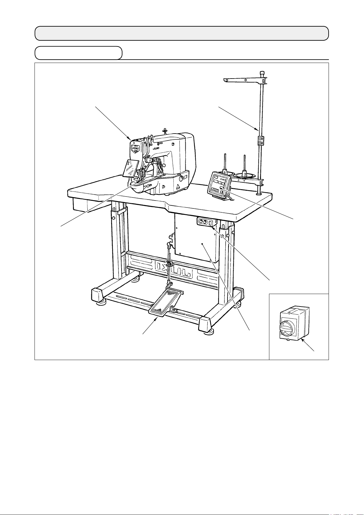
1. Names of main unit
Machine head
Work clamp feet
Thread stand
Operation panel
Power switch
Control box
Pedal switch
Power switch
(EU type)
2
Page 6
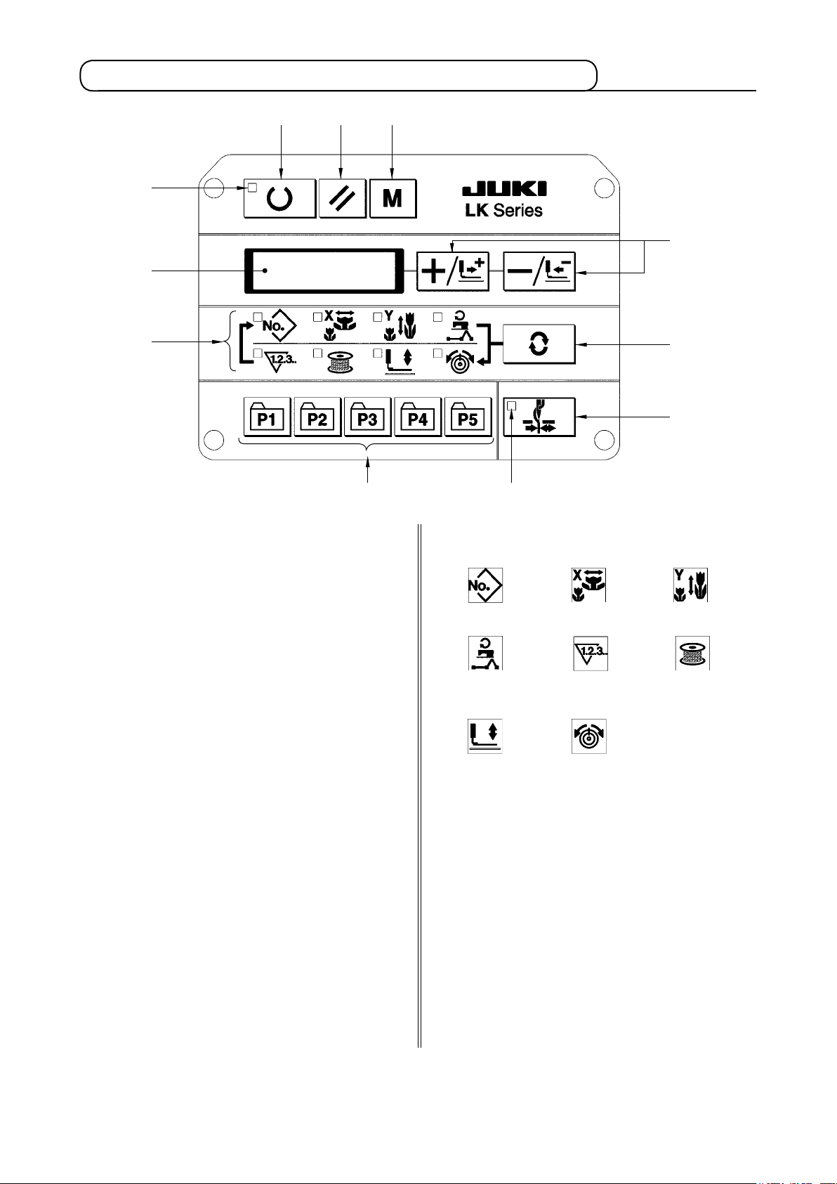
2. Names and explanation of switches on the operation panel
“Ready” key
This key changes over the setting state from the
panel to the sewing state where the sewing machine actually operates.
Sewing LED
This LED goes off at the time of setting state and
lights up at the time of sewing state. Changeover
can be performed with “Ready” key.
“Reset” key
This key is used for canceling error or returning
the set value to the initial value.
“Mode” key
This key makes the setting mode of the memory
switch.
“+/Feed forward” key and “-/Feed backward” key
This key is used for changing pattern No. and X/
Y scale, and feed forward/feed backward.
“Selection” key
This key selects the item to be set. Item selec-
tion LED of the selected item and the set value
are displayed.
Data indication LED
This LED indicates the set values of the select-
ed items such as pattern No., X/Y scale, etc.
Item selection LED
LEDs of the selected items light up.
Pattern No.
Max. speed
limitation
Work clamp
foot lowering
Needle thread clamp ON/OFF key
X scale
Sewing
counter
Thread
tension
Y scale
Bobbin
winder
This key selects effective/ineffective of needle
thread clamp. When it is effective, needle thread
clamp display LED lights up.
Needle thread clamp display LED
(Note 1)
When this LED lights up, needle thread clamp
operates.
Needle thread clamp display LED
This key registers the pattern. When this key is
pressed, the pattern registered here can sew
immediately.
X/Y scale, sewing position, etc. can be changed
and registered.
(Note 1) LK-1903AN is set to needle thread clamp prohibited (no motion) with memory switch No. 35
at the time of standard delivery.
3
Page 7
[3] INSTALLATION
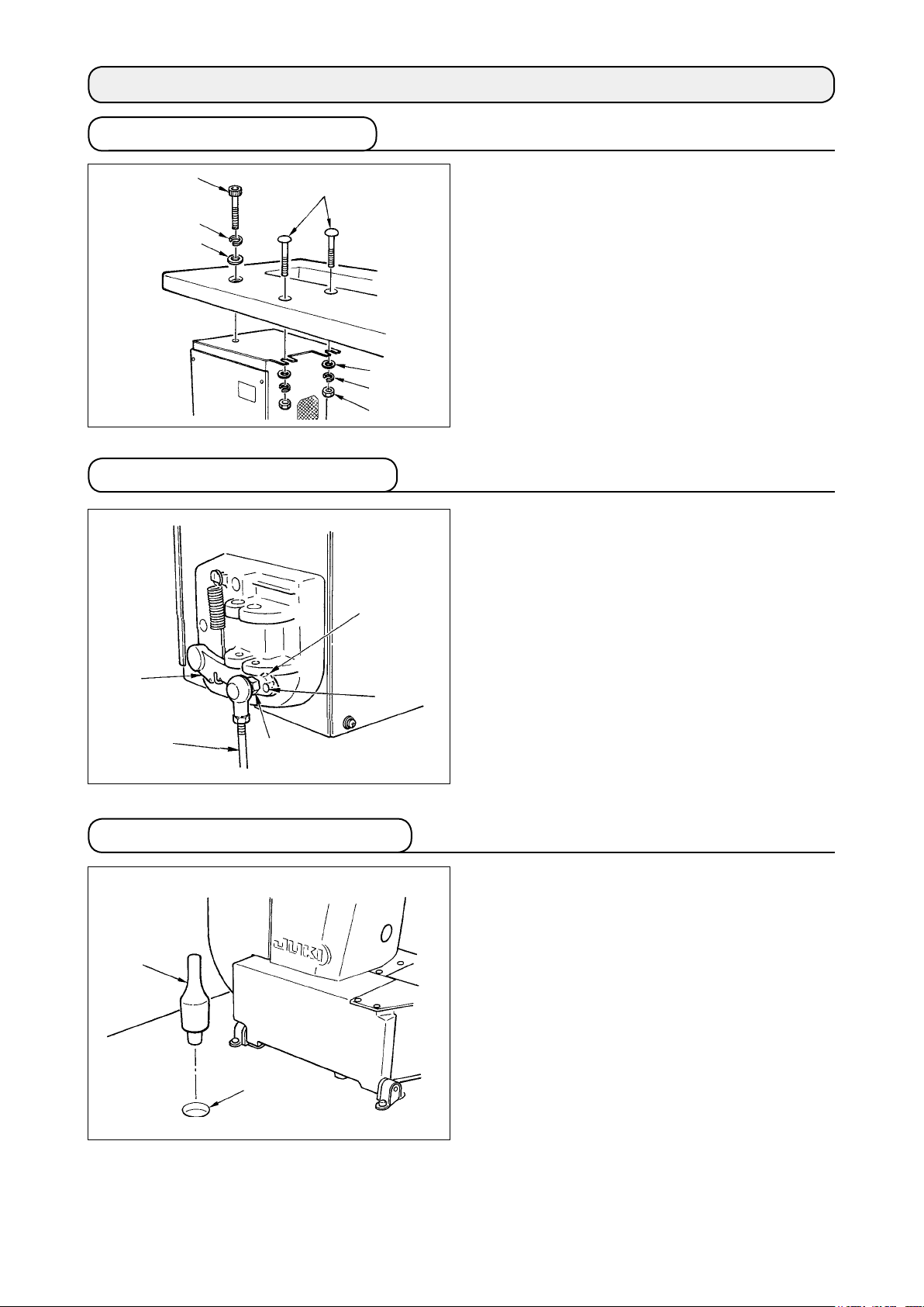
1. Installing the electrical box
2. Attaching the connecting rod
Install the electrical box on the underside of the table
at the location illustrated using round-head bolt ,
plain washer , spring washer and nut sup-
plied with the machine, and using bolt having hexag-
onal indentation on the head , spring washer
and plain washer supplied with the machine.
1) Fix connecting rod to installing hole of pedal
lever with nut .
2)
when connecting rod is installed in installing hole
, the depressing stroke of the pedal is increased.
3. Installing the head support rod
Drive head support rod in hole in the machine
table.
4
Page 8
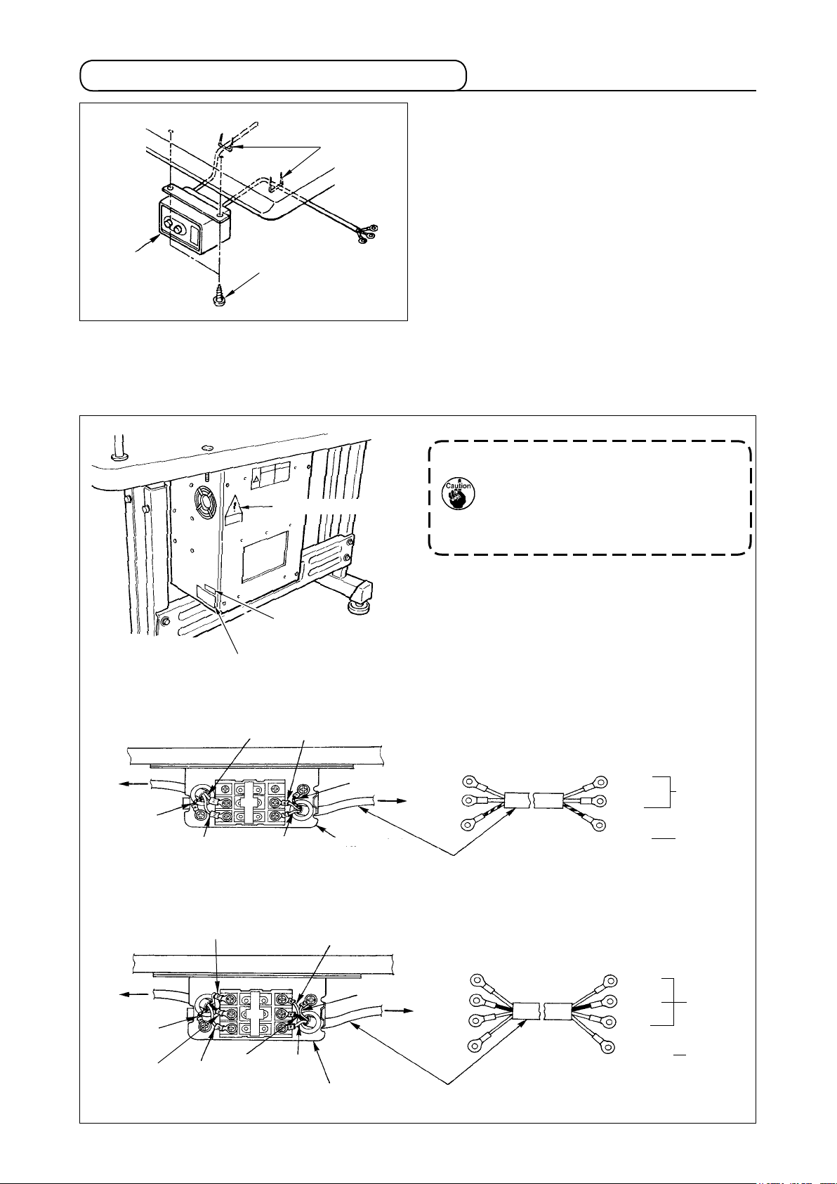
4. Installing and connecting the power switch
(1) Installing the power switch
Fix power switch under the machine table with
(2) Connecting the power source cord
Voltage specications at the time of delivery from the factry are indicated on the voltage indication seal.
Connect the cord in accordance with the specications.
Voltage caution seal
wood screws .
Fix the cable with staples supplied with the machine
as accessories in accordance with the forms of use.
* Five staples including the staple for fixing the
operation panel cable are supplied as accessories.
1. Never use under the wrong volt-
age and phase.
2. When changing the voltage, refer
to the item of ".[7]-10. Chang-
ing the voltage of 100 / 200V" p.35.
Voltage indication seal (3-phase type only)
Rating label
• Connecting single phase 200V, 220V, 230V and 240V
Light blue
Table
Control box
Green/Yellow
Brown
Light blue
Brown
Green/Yellow
Plug
Power switch
• Connecting three phase 200V, 220V and 240V
Table
Control box
Green/Yellow
Black
White
Red
Black
White
Red
Power switch
Green/Yellow
Plug
Power source cord
Power source cord
Brown
Light
blue
Green/
Yellow
White
Black
Red
Green/
Yellow
AC200 V
AC220 V
AC230 V
AC240 V
GND
AC200 V
AC220 V
AC240 V
GND
5
Page 9
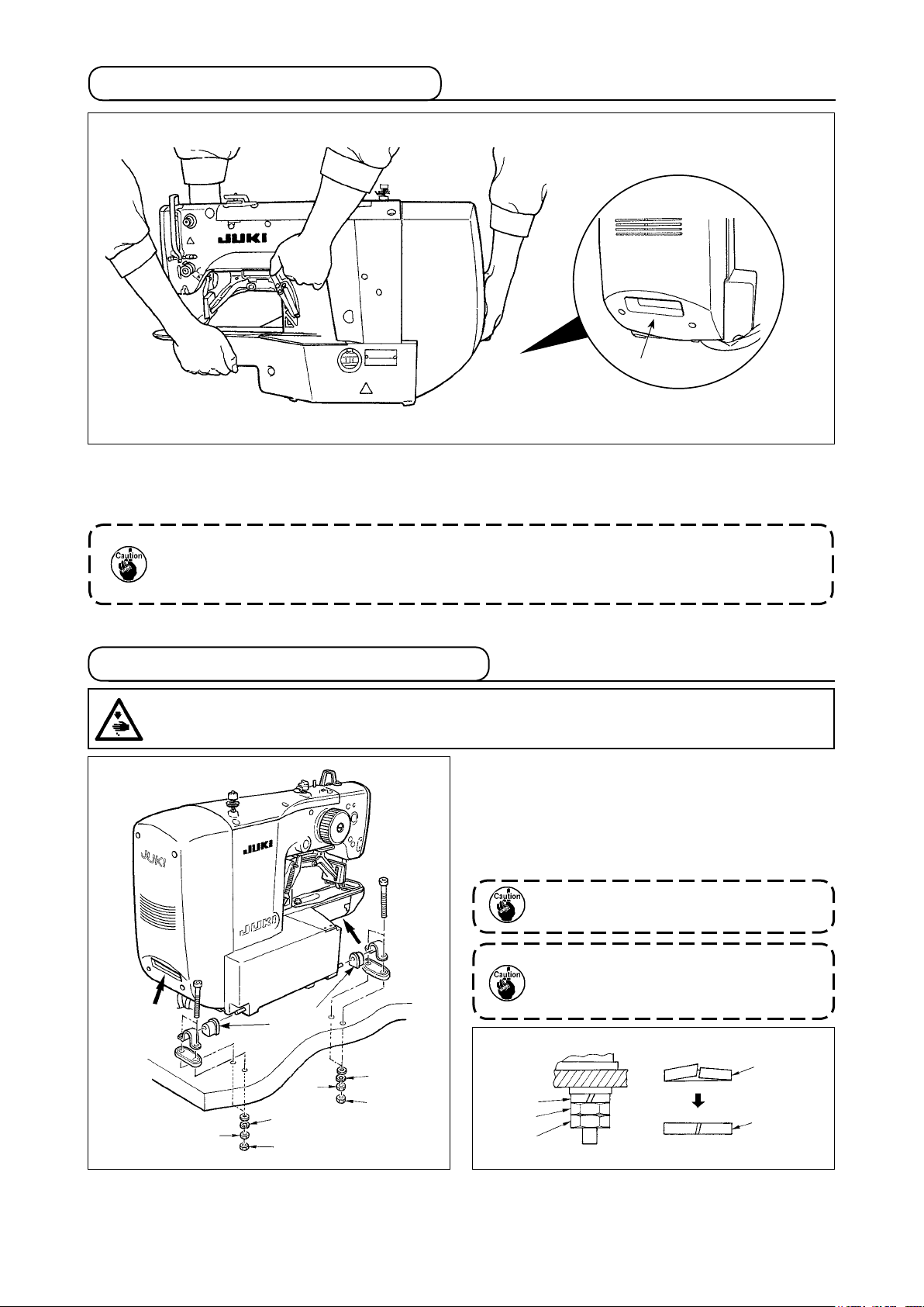
5. How to carry the sewing machine
A
To carry the sewing machine, it is necessary to hold A section and support the side faces of the sewing
machine by hand as illustrated in the gure.
1. Carefully prevent slippage of your hand that holds the cover.
2. The sewing machine weighs over 42 kg. Be sure to carry the sewing machine with two
or more people without exceptions.
6. Installation of the sewing machine head
WARNING :
To prevent possible accidents caused by the full of the sewing machine, perform the work by two
persons or more when the machine is moved.
1) Fit hinge rubber to the hinge shaft ,and x the
sewing machine main unit.
2) When tightening nut to hinge rubber , tight-
en nut until spring washer becomes as B in
the illustration, and x it with nut .
If tightening hinge rubber excessively,
it will not work properly. So, be careful.
When carrying the sewing machine, hold
sections with hands to support the
side faces of the sewing machine.
6
A
B
Page 10
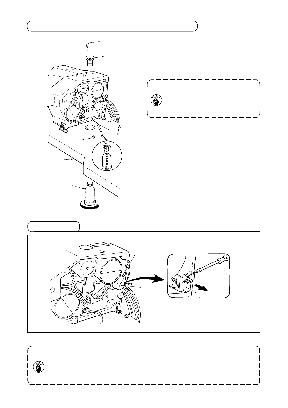
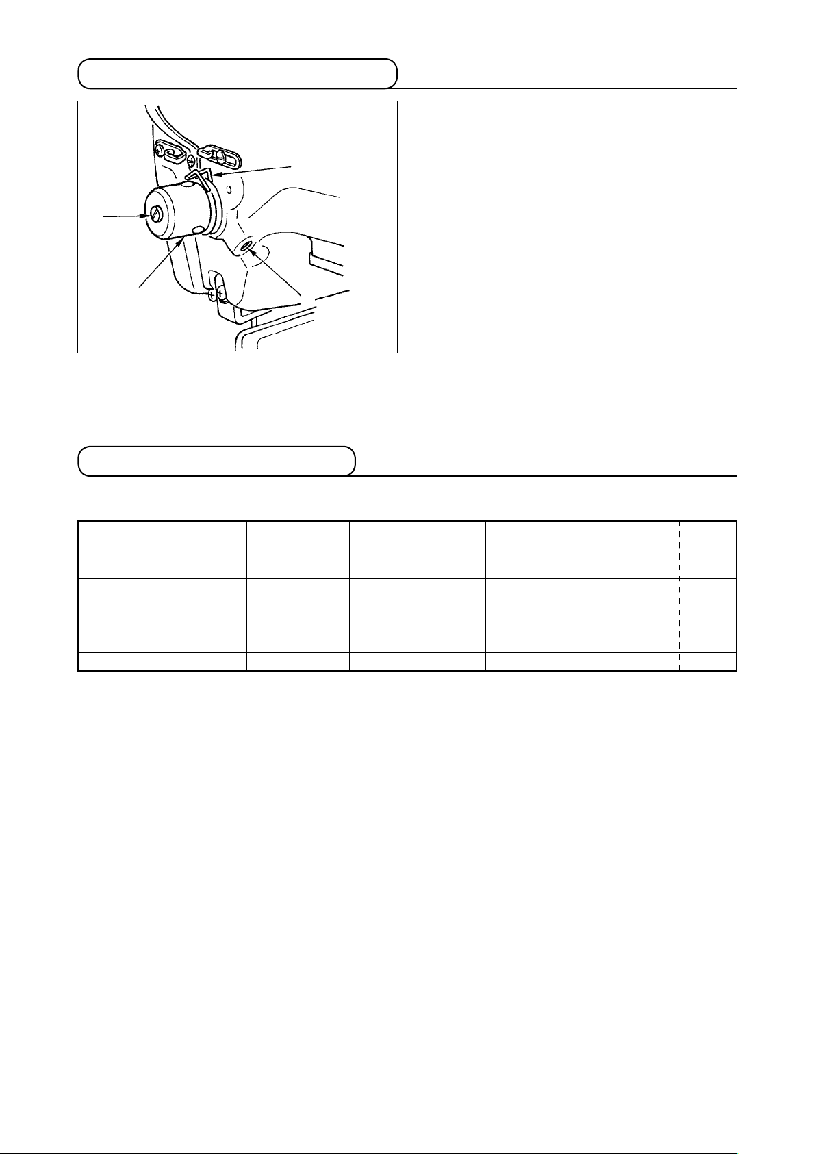
7. Installing the drain receiver and the head support rubber
1) Fix drain receiver in the installing hole of table
with two setscrews .
2) Screw in drain bin to drain receiver .
3) Insert sewing machine drain pipe into drain bin
.
4) Insert head support rubber into table .
1. Insert drain pipe until it will go no
further so that it does not come off
drain bin when tilting the machine
head.
2. Removethetapexingdrainpipe.
8. Safety switch
Remove tape xing the lever section of safety switch .
1. When using the safety switch without removing tape , it is very dangerous since the
sewing machine works even in the state that it is tillted.
2. In case error 302 occurs when the sewing machine works after setup, loosen the safe-
tyswitch ttingscrewwithascrewdriver,and lowertheswitchtothedownside ofthe
sewing machine.
7
Page 11
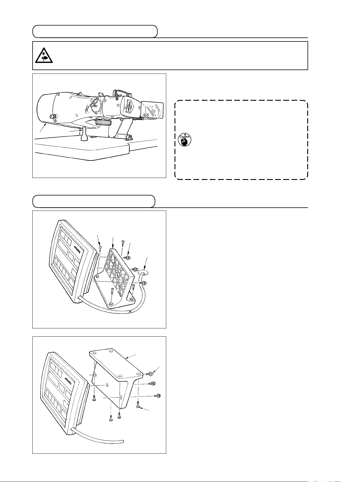
9. Tilting the sewing machine head
WARNING :
Tilt/raisethesewingmachineheadwithbothhandstakingcarenottoallowyourngerstobecaught
in the head. Turn OFF the power before starting the work so as to prevent accidents caused by abrupt
start of the sewing machine.
When tilting the sewing machine head, tilt the head
gently until it comes in contact with head support rod
.
1. Before tilting the sewing machine
head, make sure that head support rod
is attached to the machine table.
2. When raising the sewing machine
head, do not raise it while holding
motor cover . It will be the cause of
breakage of motor cover .
3.
Be sure to tilt the sewing machine head
onaatplacetopreventitfromfalling.
10. Installing the operation panel
Fix operation panel installing plate on the ma-
chine table with wood screws and pass the cable
through hole in the machine table.
Fix the operation panel on panel installing plate
with screws supplied as accessories.
Fix the cable on the bottom surface of the table with
the staples supplied with the machine as accessories.
Refer to the gure on the left side when installing the
panel under the table.
8
Page 12
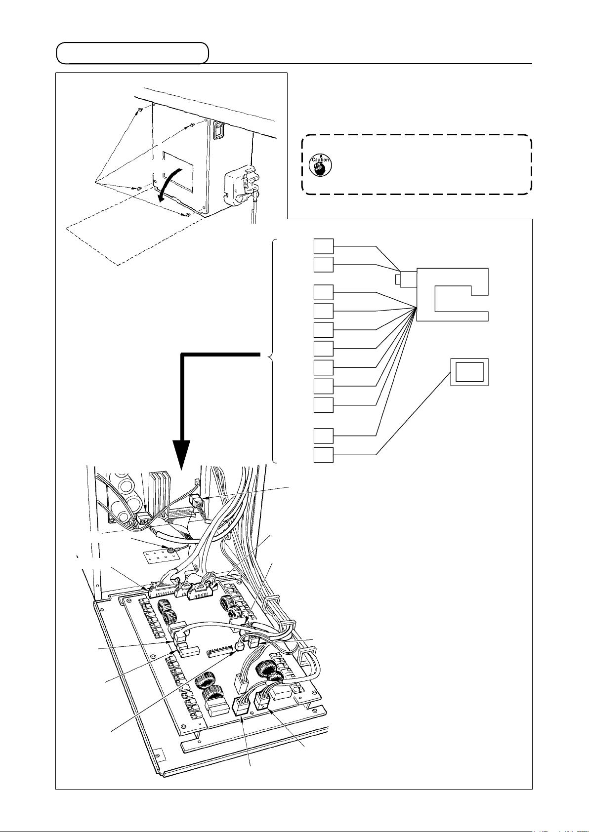
11. Connecting the cord
Slowly
Remove four screws E fixing the rear cover of the
electrical box. When opening the rear cover, press-
ing it with your hands, slowly open it by approximate-
ly 90˚ until it stops as illustrated.
Be sure to lend your hand to the rear
cover in order not to let the rear cover
fall. In addition, do not apply force to the
rear cover opened.
CN16 White
CN16
CN14
CN39
CN42
CN43
CN44
CN45
CN40
CN47
(LK-1901AN)
CN38
CN34
CN14 White
4P
9P
2P
6P
6P
6P
6P
4P
2P
16P
26P
White
White
Yellow
White
Blue
Red
Yellow
White
White
Gray
Gray
Sewing machine head
Operation panel
Earth cord
CN34 Gray
CN45
Yellow
CN47
White
CN40
White
CN38 Gray
CN44 Red
CN42 White
CN43 Blue
9
CN39 Yellow
Page 13
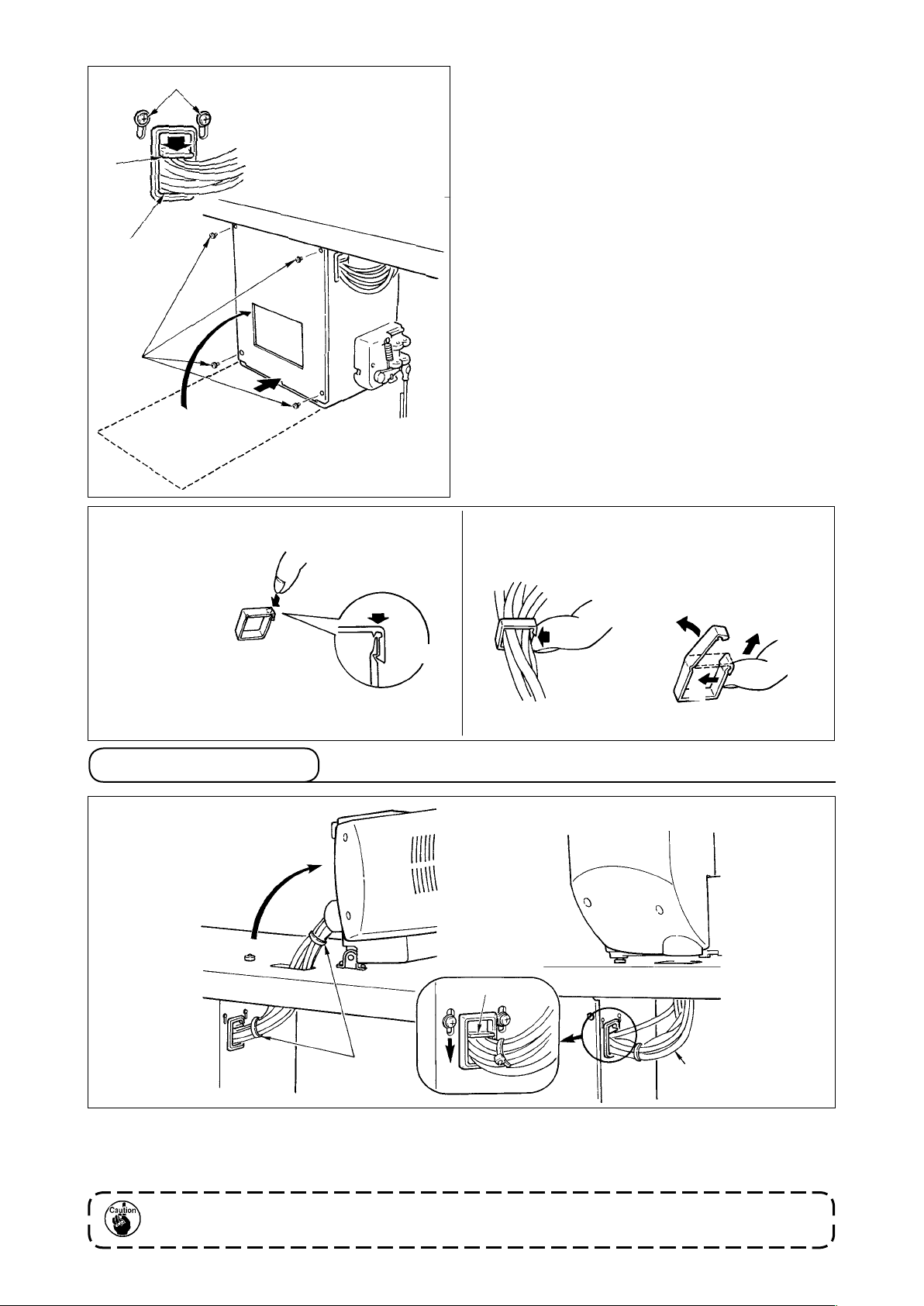
1) Take care so that the cord is not caught between
the rear cover and the electrical box main body,
close the rear cover while pressing section A on
the lower side of the rear cover, and tighten four
C
screws .
2) Lower downward the cord located on the side of
the control box and cord presser plate C in the
B
A
push hole B, press the cord and tighten screws .
How to lock the cord clamp
Lightly press the corner of clamp.
(Cord clamp is locked with a click.)
12. Managing the cord
Clamp
How to remove the cord clamp
Lightly pressing
Pull down the clamp.
The clamp goes up.
Slack
1) In the state that the sewing machine is tilted, connect the cords, and bundle them with clip band
as shown in the gure.
2) Fix the cords with cords setting plate in the state that the cords slacken as shown in the gure.
When you tilt the sewing machine, make sure that the sewing machine head support bar is
placed on the table.
10
Page 14
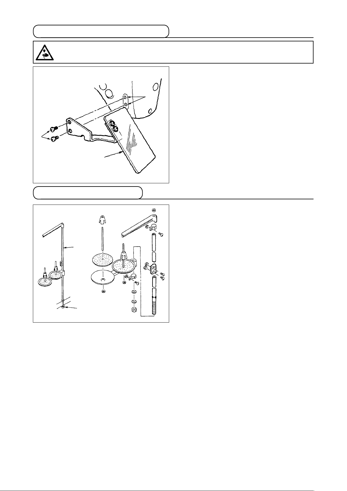
13. Installing the eye protection cover
WARNING :
Be sure to attach this cover to protect the eyes from the disperse of needle breakage.
14. Installing the thread stand
Be sure to use eye protection cover after installing
it on installing section with screws .
1) Assemble the thread stand unit, and insert it in
the hole in the machine table.
2) Tighten locknut to x the thread stand.
3) For ceiling wiring, pass the power cord through
spool rest rod .
11
Page 15
[4] OPERATION OF THE SEWING MACHINE
1. Lubrication
WARNING :
Turn OFF the power before starting the work so as to prevent accidents caused by abrupt start of the
sewing machine.
Check that the place between lower line B and upper
line A is lled with oil. Fill there with oil using the oiler
supplied with the machine as accessories when oil is
short.
* The oil tank which is lled with oil is only for lubri-
cating to the hook portion. It is possible to reduce
the oil amount when the number of rotation used
is low and the oil amount in the hook portion is
A
B
excessive. (Refer to
supplied to the hook" p.34
1. Do not lubricate to the places other
2. When using the sewing machine for
".[7]-8. Amount of oil
.)
than the oil tank and the hook of Cau-
tion 2 below. Trouble of components
will be caused.
thersttimeorafteranextendedpe-
riod of disuse, use the machine after
lubricating a small amount of oil to
the hook portion. (Refer to ".[7]-2.
Adjusting the needle-to-shuttle rela-
tion" p.31.)
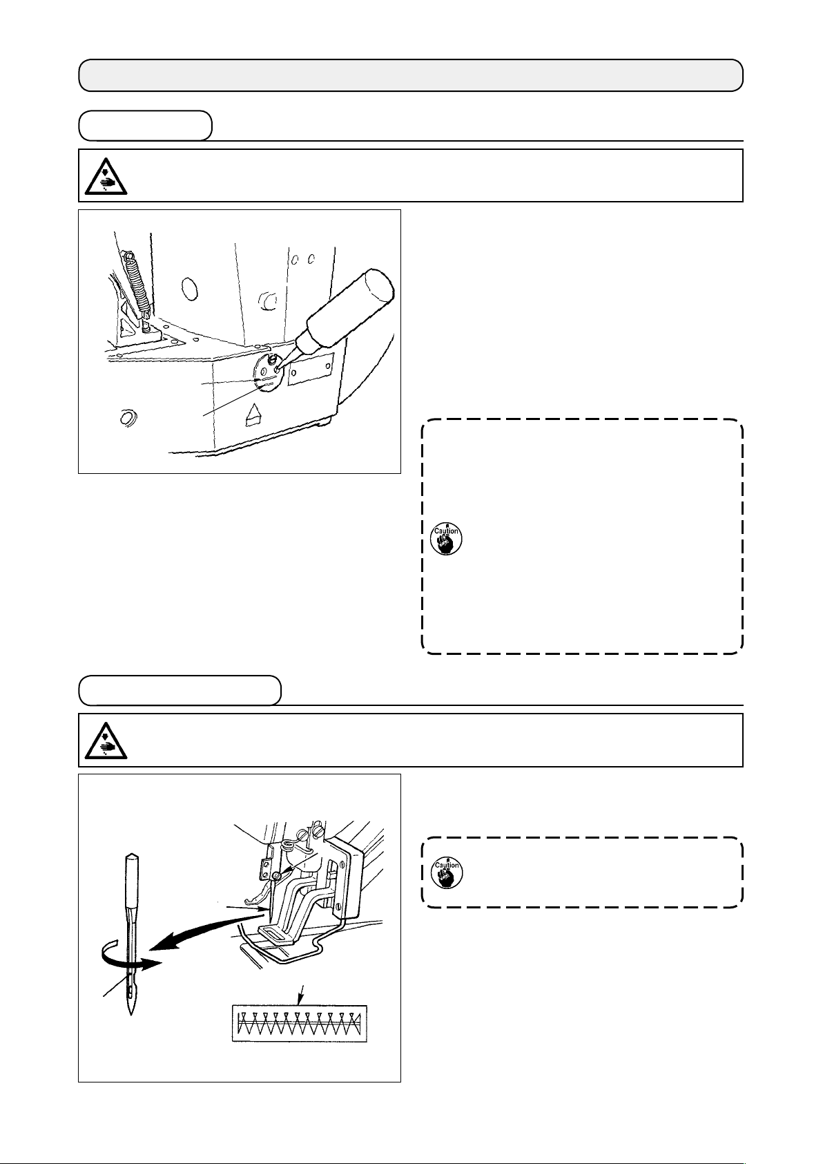
2. Attaching the needle
WARNING :
Turn OFF the power before starting the work so as to prevent accidents caused by abrupt start of the
sewing machine.
Loosen setscrew and hold needle with the long
groove facing toward you. Then fully insert it into
the hole in the needle bar, and tighten setscrew .
If the stitches are made as shown in ,
attach the needle facing to the direction
to a small extent.
12
Page 16
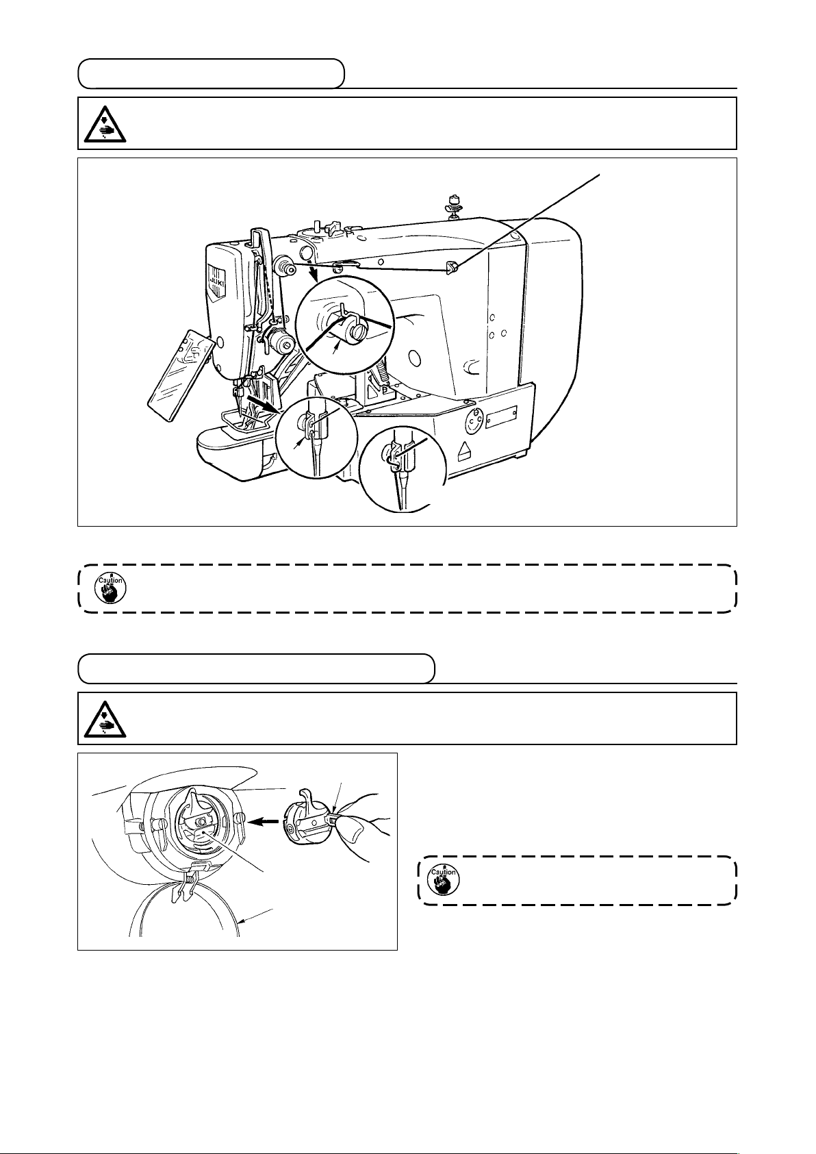
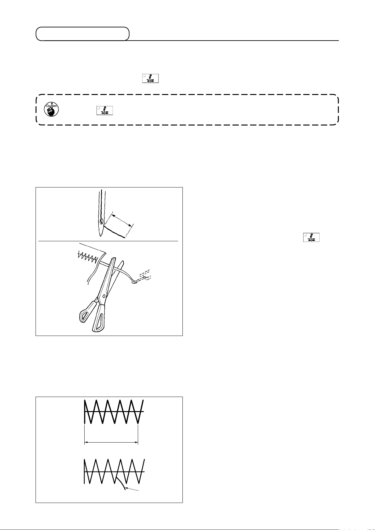
3. Threading the machine head
WARNING :
Turn OFF the power before starting the work so as to prevent accidents caused by abrupt start of the
sewing machine.
Thin synthetic thread or the like
Pull out the thread by approximately 40mm from the needle after threading through the needle.
1. When the silicon oil is used, thread through thread guide for silicon (Optional)
2. For thick thread, pass the thread through one hole only of needle bar thread guide .
4. Installing and removing the bobbin case
WARNING :
Turn OFF the power before starting the work so as to prevent accidents caused by abrupt start of the
sewing machine.
1) Open hook cover .
2) Raise latch of bobbin case , and remove the
bobbin case.
3) When installing the bobbin case, fully insert it into
the shuttle shaft, and close the latch.
If it is not fully inserted, bobbin case
may slip off during sewing.
13
Page 17
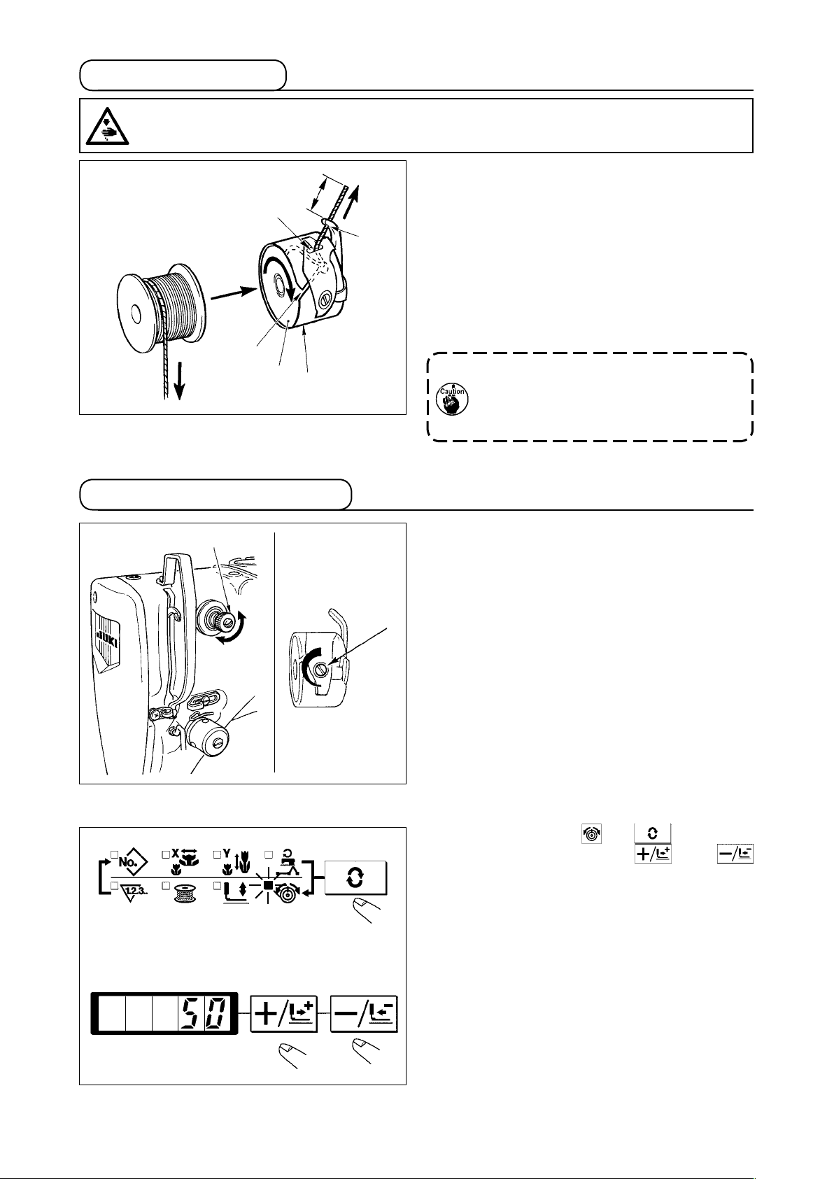
5. Installing the bobbin
WARNING :
Turn OFF the power before starting the work so as to prevent accidents caused by abrupt start of the
sewing machine.
25mm
1) Set the bobbin into bobbin case in the di-
rection shown in the gure.
2) Pass the thread through thread slit of bobbin
case , and pull the thread as it is. By so doing,
the thread will pass under the tension spring and
be pulled out from thread hole .
3) Pass the thread through thread hole of the
horn section, and pull out the thread by 25mm
from the thread hole.
If the bobbin is installed in the bobbin
case orienting the reverse direction, the
bobbin thread pulling out will result in
an inconsistent state.
6. Adjusting the thread tension
Long
Short
Adjusting the needle thread tension
If thread tension controller No. 1 is turned clock-
wise, the length of remaining thread on the needle
after thread trimming will be shorter. If it is turned
counterclockwise, the length will be longer.
Shorten the length to an extent that the thread is not
slipped off.
Adjust needle thread tension from the operation pan-
el and bobbin thread tension with .
1) Select thread tension with key.
2)
Set needle thread tension with key or
key. There is a setting range of 0 to 200. When the
set value is increased, the tension becomes higher.
* The tension is set so that 1.5 N (spun thread
#50) is obtained at the set value 50 at the time
of standard delivery. (When thread tension No.
1 is released.)
14
Page 18
7. Adjusting the thread take-up spring
8. Example of the thread tension
The standard stroke of thread take-up spring is 8
to 10 mm, and the pressure at the start is 0.1 to 0.3N.
1) Adjusting the stroke
Loosen setscrew , and turn thread tension
asm. .
Turning it clockwise will increase the moving
amount and the thread drawing amount will in-
crease.
2) Adjusting the pressure
To change the pressure of the thread take-up
spring, insert a thin screwdriver into the slot of
thread tension post while screw is tightened,
and turn it. Turning it clockwise will increase the
pressure of the thread take-up spring. Turning it
counterclockwise will decrease the pressure.
When using the sewing machine for the rst time, adjust the thread tension referring to the table below.
Thread
Polyester lament thread #50
Polyester spun thread #50
Polyester spun thread #60
(Thread clamp OFF)
Cotton thread #50
Cotton thread #20
Material
Wool
Wool
T/C broad
Denim
Denim
Needle thread tension
setting
30 to 35
50 to 55
30 to 35
35 to 45
35 to 45
Thread take-up spring moving
amount [Thread drawing amount]
10mm [13mm]
10mm [13mm]
8 to 10mm [11 to 13mm]
10mm [13mm]
8 to 10mm [11 to 13mm]
Strength
0.1N
0.2N
0.1N
0.1N
0.1N
15
Page 19
[5] OPERATION OF THE SEWING MACHINE (BASIC)
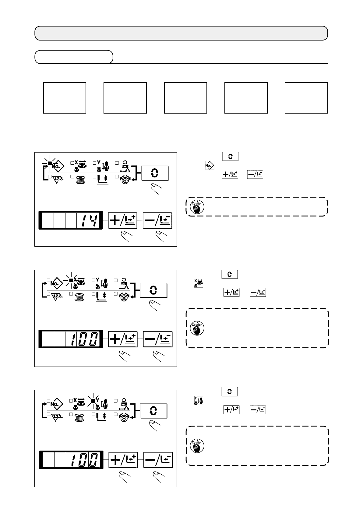
1. Item data setting
Set each item following the procedure described below.
Setting of the
pattern No.
(1) Turn ON the power switch.
Pattern No. of the item selection lights up, and the pattern No. is indicated on the data display.
(2) Setting of the pattern No.
Setting of the
X scale
Setting of the
Y scale
1) Press the key to indicate the item “Pattern
2) Press the or key to indicate “ 14 ”on
NO” .
the display. (Pattern No. is set to 14.)
Setting of the
max. sewing
speed limitation
Refer the pattern No. to the separate table.
(3) Setting of the X scale
Setting the
thread tension
(4) Setting of the Y scale
1) Press the key to indicate the item “X Scale”
.
2) Press the or key to indicate “100”.
(Set X scale to 100%.)
The setting exceeding 100% is danger-
ous since needle and the cloth presser
interferes with each other and needle
breakage or the like will occur.
1) Press the key to indicate the item “Y Scale”
.
2) Press the or key to indicate “100”.
(Set Y scale to 100%.)
The setting exceeding 100% is danger-
ous since needle and the cloth presser
interferes with each other and needle
breakage or the like will occur.
16
Page 20
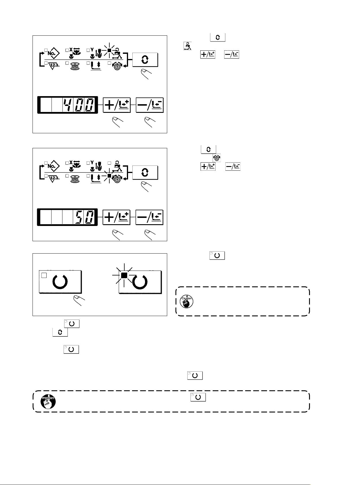
(5) Setting of the max. sewing speed limitation
(6) Setting the thread tension
1) Press the key to indicate the item “Speed”
.
2) Press or key to indicate “400”. (Setting of 400 sti/min)
1) Press key to indicate the item “THREAD
TENSION” .
2) Press or key to indicate “50”. (0 to
200 can be set.)
(7) Finish of setting
1) Press the key.
2) After the work clamp feet have moved and gone
up, the sewing LED lights up, and the sewing is
* When key is pressed, the set values of pattern No., X/Y scale, etc. are memorized.
* If key is pressed, you can make sure of the respective setting items again. However, the items
can not be changed in the state that the SEWING LED is lit up.
*
When key is pressed, the READY LED goes off. Set values of the respective items can be changed.
* Thread tension can be changed even when the sewing LED lights up. Thread tension can be mom-
orized with the start switch as well.
ready.
When the presser is raised, be careful that
ngersarenotcaughtinthepressersince
the presser moves after having lowered.
* Use the machine after conrming the pattern No. When key is pressed while pattern No. is indicat-
ed "0" (state at the time of delivery), error display E-10 appears. At this time, re-set the pattern No.
When turning OFF the power without pressing key, the set values of pattern No., X/
Yscale,numberofmax.rotation,andthreadtensionarenotmemorized.
17
Page 21
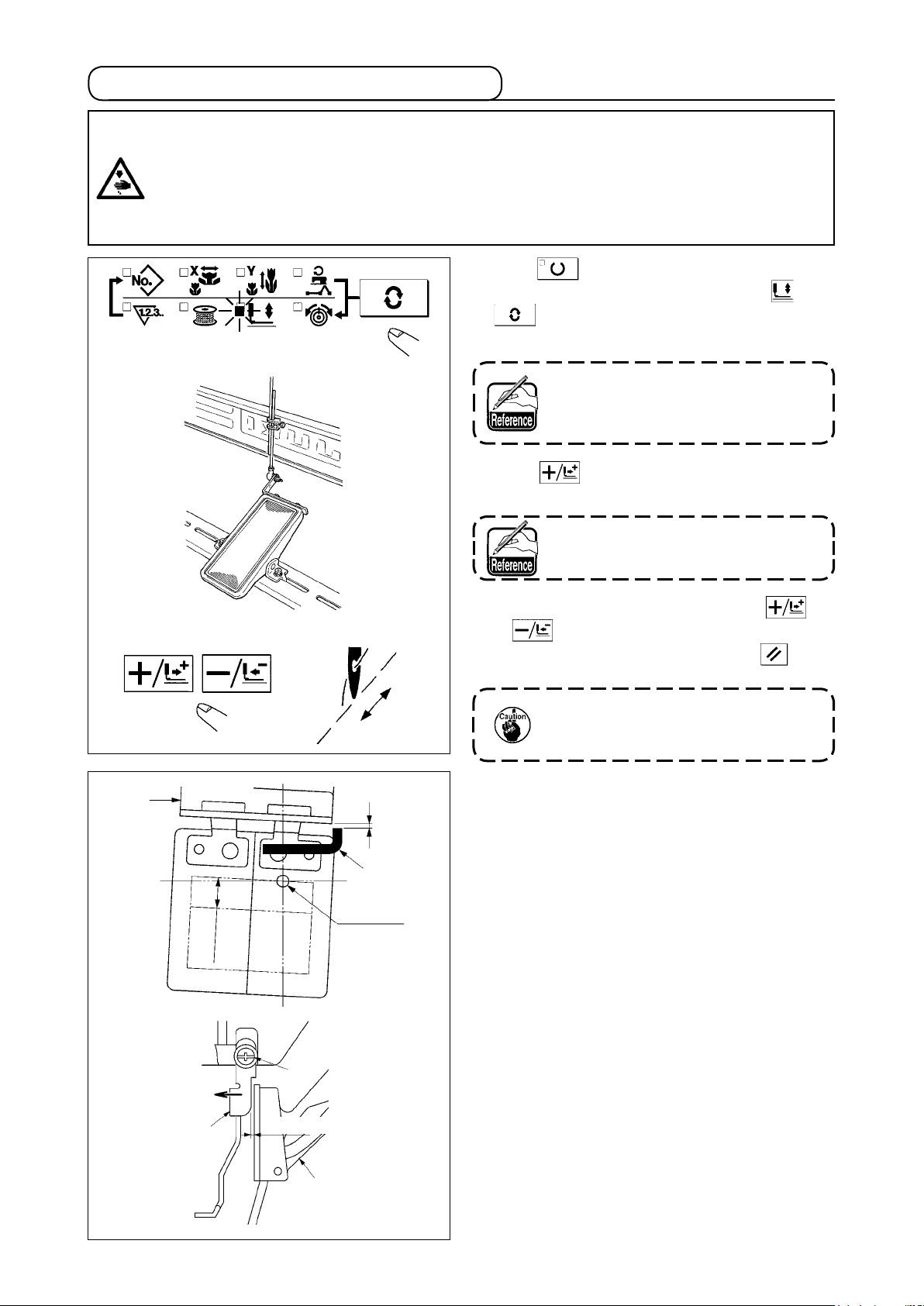
2. Checking the contour of a sewing pattern
WARNING :
2. When making sure of the contour of the sewing pattern, press + / - key with the needle bar lowered,
1. Make sure without fail of the contour of the sewing pattern after selection of the sewing pattern.
If the sewing pattern extends outside the work clamp feet, the needle will interfere with the work
clamp feet during sewing, causing dangerous troubles including needle breakage.
and the work clamp feet move after automatically making the needle bar return to the upper position.
1)
Press key to make the READY LED light up.
2) Select the work clamp foot lowering with
key.
3) Lower the work clamp feet with the foot switch.
⇩
The sewing machine does not start
even when the foot switch is de-
pressed under this mode.
4) Press key in the state that the work clamp
feet are lowered.
❷
10mm
⇩
➡
Clearance
❶
Needle
The work clamp feet do not go up even
when the foot switch is detached.
5) Conrm the contour of the pattern with key
or key.
6) The work clamp feet will go up when key is
pressed.
The work clamp feet do not come
down immediately after turning ON
the power.
(Caution) When using a sewing pattern which is
full in lengthwise direction (+10 mm),
make sure of the clearance between
cloth feed base ❷ and wiper base ❶.
If there is no clearance, loosen set-
screw ❸ and move the wiper to the
needle side. Especially when the nee-
dle position comes to the rear on the
right side, the clearance is decreased.
❶
❸
Clearance
❷
-
18
-
Page 22
3. Sewing
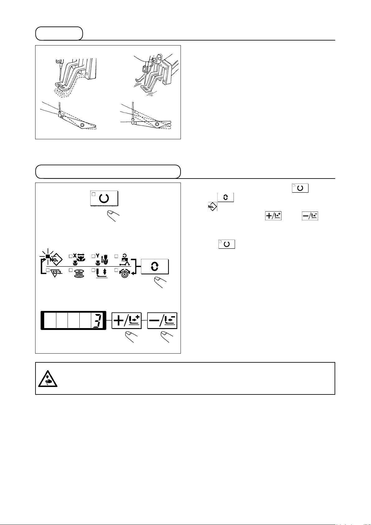
4. Change to the other sewing pattern
1) Set a workpiece on the work clamp foot section.
2) Depress the pedal switch to the rst step, and the
work clamp feet will come down. If you detach
your foot from the pedal switch, the work clamp
feet will go up.
3) Depress the pedal switch to the second step after
descending the work clamp feet at the rst step,
and the sewing machine will start sewing.
4) After the sewing machine completes sewing, the
work clamp feet will go up, and return to the sew-
ing start position.
1) Make the Sewing LED go off with key.
2) Press key and select the item of pattern
No .
3) Set the pattern No. with key or key
4) Similarly, setting of X/Y scale, speed, etc. is per-
formed.
5) When key is pressed, the Sewing LED
lights up and the sewing machine is in the sewing
ready state.
WARNING :
Make sure without fail of the contour of the sewing pattern after selection of the sewing pattern.
If the sewing pattern extends outside the work clamp feet, the needle will interfere with the work
clamp feet during sewing, causing dangerous troubles including needle breakage.
19
Page 23
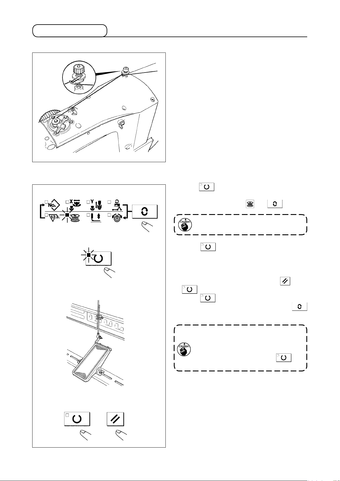
5. Winding a bobbin
5-1. To wind a bobbin while the sewing machine is performing sewing
Thread the bobbin winder and wind the bobbin
thread onto the bobbin as illustrated in the gure.
5-2. To wind a bobbin independently
1) Press key to make the SEWING LED go
off.
2) Select the bobbin winder with key.
Selection cannot be performed when the
Sewing LED is lit up.
3) Press key. The work clamp feet come
down and the Sewing LED lights up.
4) When the pedal switch is depressed, the sewing
machine rotates.
5) When the pedal is depressed again, or key or
key is pressed, the sewing machine stops.
6) When key is pressed, the Sewing LED
goes off, the work clamp feet go up and
key becomes effective.
Bobbin winder does not work immediate-
ly after turning ON the power. Perform the
bobbin winding after setting pattern No.
or the like once, pressing the key,
and making the sewing LED light up.
20
Page 24
6. Thread clamp device
Trouble of sewing (slip-off of needle thread, stitch skipping, or stain of needle thread) at the time of high-
speed start can be prevented with the thread clamp device. The thread clamp device works in the state
that the thread clamp indication LED lights up and does not work when the LED goes off. Changeover of
ON/OFF motion is performed with key. When the thread clamp device is OFF, the start automatically becomes the slow start.
1. When memory switch No. 35 is "1" (prohibited), the thread clamp does not work. In ad-
dition, key is ineffective.
2. Memory switch, refer to ".[8] HOW TO USE THE MEMORY SWITCH" p.37.
* Matters that demand special attention when using the needle thread clamp device
(1) In case of with the needle thread clamp (motion), make shorter the length of needle thread remaining on
the needle at the sewing start for use. When the length of needle thread is lengthened, needle thread on
the wrong side of material is apt to protrude. In addition, when the length is excessively lengthened, the
end of needle thread held by the needle thread clamp may be rolled in the seams.
1)
33 to 36mm
3)
1) In case of with the needle thread clamp, the stan-
dard of the length of needle thread is 33 to 36
mm.
2)
When needle thread is long after replacing thread
or the like or sewing while holding needle thread by
hand, turn OFF the THREAD CLAMP key.
3) When the needle thread held with the thread
clamp is rolled in the seams, do not draw the
material forcibly and cut the connecting needle
thread with the scissors or the like. The seams
are not damaged since it is the needle thread at
the sewing start.
(2) It is possible to adjust needle thread shorter by making the needle thread clamp work while holding the
stabilized sewing at the start of sewing and the gathering (bird's nest) of needle thread on the wrong side
of material can be lessened. However, for the pattern which the stitch length for neatly rolling in needle
thread is short, needle thread may protrude from the wrong side of material. Select with/without thread
clamp referring to the item below.
1) When the sewing length is short (less than ap-
(Right side)
proximately 10 mm), the end of needle thread
may protrude like beard even when adjusting
needle thread shorter.
10mm
(Wrong side)
Needle thread
21
Page 25

(3) When the type of lower plate that material does not come in close contact with throat plate is used,
needle thread on the wrong side of material may be rolled in the seams regardless of needle thread play
or sewing length.
(Wrong side)
Needle thread
(4) For LK-1903AN (button sewing), the thread clamp is set to the motion prohibited in the state of standard
delivery due to the aforementioned (2) and (3). For (memory switch No. 35) with cross-over stitch ( ,
etc.) or X shape ( , etc.), needle thread on the wrong side of material becomes easy to be rolled in. In
this case, it is recommended to use the thread clamp.
(5) When the thread clamp is used, and bobbin thread at the sewing start appears on the right side of material,
reduce thread tension at the sewing start (2 to 3 stitches) and bobbin thread becomes less conspicuous.
[Example of setting] Tension of 1 to 2 stiitches at the sewing start is “20” when sewing tension setting is “35”.
* For the setting of tension at the sewing start, refer to
". [6]-5. Setting the pattern thread tension"
p.29
22
Page 26

[6] OPERATION OF THE SEWING MACHINE (ADVANCED)
1. Performing sewing using the pattern keys ( , , , and )
Patterns (No.1 to 200) which have been already registered can be registered to P1 to P50. It is possible
to change and register the scale, max. speed limitation, thread tension and sewing position. Same as the
patterns (No.1 to 200), P1 to P50 are used by the selection by scrolling the pattern Nos. The pattern call-
ing from P1 to P25 can be made by one-touch as well.
* When selecting P6 to P25, perform the selection by combination (simultaneous pressing) of ,
, , and keys as shown in the table below.
P-No. Selection key P-No. Selection key P-No. Selection key P-No. Selection key
P1 P1 P8 P1+P4 P15 P4+P5 P22 P2+P3+P4
P2 P2 P9 P1+P5 P16 P1+P2+P3 P23 P2+P3+P5
P3 P3 P10 P2+P3 P17 P1+P2+P4 P24 P2+P4+P5
P4 P4 P11 P2+P4 P18 P1+P2+P5 P25 P3+P4+P5
P5 P5 P12 P2+P5 P19 P1+P3+P4
P6 P1+P2 P13 P3+P4 P20 P1+P3+P5
P7 P1+P3 P14 P3+P5 P21 P1+P4+P5
(1) Register to the pattern key
Setting example : Register following setting to the P2., Pattern No. 3, X scale rate : 50%, Y Scale rate :
80%, Max. speed limitation : 2,000 sti/min, Thread tension : "50", Pattern position : 0.5
mm to the right and 1 mm to the front
1) Turn ON the power switch and press
key to enter mode setting (memory switch
setting). (Sewing LED should be put out.)
2) Indicate the pattern register mode with
or key.
3) Press key.
Enter the pattern register mode.
4)
Press key. (Select P-No. to be registered.)
Selection can be performed with or
key.
5)
Press key to indicate the Pattern No .
Set the Pattern No. to "3" with or
key.
23
Page 27

6) Press key and set as follows with
or key.
X Scale rate : “50”%, Y Scale rate :
“80”%, Max. speed limitation : “2000” sti/
min, Thread tension : “50”
7) Press key and “X Scale rate ” indi-
cation becomes 0.0. Traveling amount in X di-
rection can be set in 0.1 mm unit. Set 0.5 with
or key.
8) Press key and “Y Scale rate ” indication becomes 0.0. Traveling amount in Y
direction can be set in 0.1 mm unit. Set –1.0
with or key.
9) Press key to nalize the setting.
10) Press key.
Pattern register mode is nalized.
11) Press key.
Mode setting is nalized and the mode returns to the normal mode.
24
Page 28

(2) Sewing operation
Operation example : After performing sewing with the contents of the registered P2, perform sewing with
the contents of P3.
1) Turn ON the power switch.
2) Press the key.
3) Press the key, and when the sewing LED
lights up, the work clamp foot goes up after it has
moved.
⇩
⇩
⇔
4) Check the contour of the sewing pattern.
(Refer to the item
tour of a sewing pattern" p.18.)
5) If the contour of the sewing pattern is acceptable,
the sewing can be made.
6) Press key after completion of sewing and
the presser comes down. The presser moves to
the sewing start point after origin retrieval and
goes up. (The P keys can operate the pattern
chage by one-touch even when the sewing LED
is lighting up.)
7) Perform the above items 4) and 5).
"Ⅰ.[5]-2. Checking the con-
➡
* The P1 to P25 can be indicated on the display
when selecting the pattern by pressing the
or key.
⇩
0 to 200
→
←→
P1 to 25
←
➡
⇩
⇔
P1 to P25 which have not been registered are not
indicated.
Press P1 to P25 key while the sewing
LED lights up and the presser comes
down. Be careful that your fingers are
not caught in the presser.
Pattern register from P26 to P50 can be
performed. Register can not be performed
in to key. Designate the pattern
by the pattern selection only. Indicate the
pattern with or key.
0 to 200
→
Pattern selection from P26 to P50 cannot be performed while the sewing LED
lights up.
P1 to P25
←→
P26 to P50
←→
←
-
25
-
Page 29

2. Performing sewing using the combination function
By arranging in the order of use of the pattern register (P1 to P50) which have been already registered
and registering in C1 to C20, the sewing pattern will change in the order every time the sewing machine
nishes the sewing. Every one combination No. can be registered up to the maximum 30 patterns.
(1) Register of the combination
Setting example : Combine in the order of P1, P2 and P3, and register them in the C1.
1) Turn ON the power switch and press key
to enter the mode setting (memory switch set-
ting). (Sewing LED should be put out.)
2) Indicate the combination mode with or
key.
3) Press key. Sewing LED lights up to enter the combination mode.
C1 to C20 can be selected with or
key.
4) Press key, and then press key.
P1 is set to the rst pattern of C1. P1 to P50 can
be selected with or key as well.
5) Press key, and then press key.
P2 is set to the second pattern of C1. P1 to P50
can be selected with or key as well.
6) Press key, and then press key.
P3 is set to the third pattern of C1. P1 to P50 can
be selected with or key as well.
7) Press key to nalize the register.
8) Press key.
Combination register mode is nalized.
9) Press key.
Mode setting is nalized and the mode returns
to the normal mode.
26
Page 30

(2) Sewing operation
Operation example : Perform sewing with the contents of the registered C1.
1) Turn ON the power switch.
2) Set the pattern No. to “C1-1 ” using the or
key. Scroll as follows :
0 to 200 P1 to P50 C1 to C20
3) Press the key. When the sewing LED lights
up, the work clamp feet will go up after having
moved.
4) If the contour of the pattern is acceptable, the
sewing can be made.
5) Every time the sewing is nished, the step is made
in the order of the combination. After completing
one cycle of sewing, the step returns to the first
step. The sewing can be made repeatedly.
“C1. 1” “C1. 2” “C1. 3”
* When you desire to return the pattern to the pre-
vious one or skip the next pattern after sewing,
press or key in a state that the sewing LED lights up. The indication of the pattern
will change, and the work clamp feet will move to
the sewing start point.
* If the contents of P1 to P50 are changed after reg-
istration of C1 to C20, the contents of P1 to P50
used in C1 to C20 will change. So, be careful.
* Make sure of the contour of the pattern for each
of the patterns. (Refer to the item
Checking the contour of a sewing pattern"
p.18
.)
".[5]-2.
27
Page 31

3. Performing sewing using the “bobbin thread counter”
The production counter can be used as the bobbin thread counter. In case a same sewing pattern is sewn
in repetition, the sewing machine will stop sewing when the number of times (the specied number) that
can be sewn with a bobbin is reached. The bobbin thread counter is of the subtracting method.
The counter at the time of delivery is set to the production counter (adding method).
If it is used as the bobbin thread counter, it is necessary to change over memory switch
No. 18. (Refer to the item ".[8] HOW TO USE THE MEMORY SWITCH" p. 37.)
1) Press key to indicate the Counter .
2) Then press the key.
3) Then press the or key, and set the
specied number of times that can be sewn with
a bobbin.
4) Every time the sewing machine nishes a sewing
cycle, counting-down is made by one.
5) When the sewing machine nishes the specied
number of times, the sewing machine does not
start even if depressing the pedal.
6) Replace the bobbin with a new one, and press
the key. The value of the counter returns to
the set value.
7) Repeat the steps of procedure from the steps 4)
to 6).
4. How to use the temporary stop
When memory switch No. 31 is set to "1", key can be used as the temporary stop key. (Refer to
".[8] HOW TO USE THE MEMORY SWITCH" p.37
1) Sewing machine stops by means of key.
Error 50 is indicated, the error release is per-
formed using key.
2) There are three operations after the release as below.
Re-start of sewing by means of the start switch.
.)
Press key to perform thread trimming, perform positioning with or key, and re-
start by means of the start switch.
Press key to perform thread trimming, and press again key to return to the origin.
28
Page 32

5. Setting the pattern thread tension
Needle thread tension for 6 stitches at the sewing start, the portion which is changed over from basting
stitch to zigzag stitch, and the portion of tie stitch at the sewing end can be individually set.
1)
2)
3), 4)
1) While the sewing LED lights up, press key
to indicate the needle thread tension .
2) Lower the presser with the foot pedal.
When the foot pedal is depressed until
it will go no further, the sewing machine
starts. So, be careful.
3) Move the feed with key.
4) “c” is indicated at the position where the tension
setting is possible.
5) Pressing key, set the tension with or
key.
6) Repeat steps 3), 4) and 5) to set the tension.
7) When setting is completed, press key.
The presser moves to the origin and goes up.
5)
7)
29
Page 33

6. Cautions in operation
(1) When the error indicator lamp lights up, be sure to check the cause of trouble and take a proper cor-
rective measure.
(2) Do not draw, by hand, the material being sewn during sewing. Doing so will cause the needle shift
from the correct position. If the needle moves from the correct position, press the key two times.
This will return the needle to the normal origin.
(3) Do not turn OFF the power in a state that the needle is lowered. The presser comes down and the
wiper interferes with needle. As a result, there is a danger of needle breakage or the like.
Reference for the sewing speed to be applied
Sewn product / thread / needle Head type / Sewing speed
8-layered denim / Cotton thread #50 / DPx5 #16 S (Standard) / 3,200 sti/min
8-layered woolen gabardine / Polyester lament #50 / DPx5 #14 S (Standard) / 2,300 sti/min
8-layered denim / Cotton thread #20 / DPx17 #19 H (Heavy-weight material)/3,200 sti/min,
W (Double-capacity hook)/2,700 sti/min
Overlapped sewing of 6 x 12-layered denim / Cotton thread #20 / DPx17 #19
Tricot + shoulder strap (3 + 1) layered section / Polyester spun #60 / DPx5 #11 F (Foundation) / 2,000 sti/min
* To prevent the thread breakage due to the needle heat, set the sewing speed referring to the above ta-
ble in accordance with the sewing conditions.
* For sewing the foundation or the like, lower the height of the needle bar to prevent the stitch skipping.
(Refer to the item “Adjusting the height of the needle bar”)
H (Heavy-weight material) / 2,500 sti/min
[7] MAINTENANCE
1. Adjusting the height of the needle bar
WARNING :
Turn OFF the power before starting the work so as to prevent accidents caused by abrupt start of the
sewing machine.
: Engraved line
for DP x 5
: Engraved line
for DP x 17
is for H and W types only
Bring needle bar to the lowest position of its stroke. Loosen needle bar connection screw and adjust
so that upper marker line engraved on the needle bar aligns with the bottom end of needle bar bushing, lower . For F type only, adjust the needle bar to the position where it is lowered by 0.8 mm to 1 mm
from the center of upper marker line engraved on the needle bar.
: Upper
engraved line
0.8 to 1mm
F type only.
After the adjustment, make sure that there is no uneven torque.
When stitch skipping occurs in accordance with the sewing conditions, adjust the height of the needle
bar so as to lower it by 0.5 to 1 mm from the needle bar engraved line .
30
Page 34

2. Adjusting the needle-to-shuttle relation
WARNING :
Turn OFF the power before starting the work so as to prevent accidents caused by abrupt start of the
sewing machine.
Relation between needle and engraved lines
0 mm
1) Turn the handwheel by hand. When needle bar
has gone up, adjust so that lower marker line
engraved on the needle bar aligns with the
bottom end of the needle bar bushing , lower.
2) Loosen setscrew in the driver. Open inner
hook pressers to the right and left, and re-
move inner hook presser .
At this time, be careful not to let inner
hook come off and fall.
3)
Adjust so that the blade point of inner hook aligns
with the center of needle , and that a clearance
of 0 mm is provided between the front end of the
driver and the needle as the front end face of driver
receives the needle to prevent the needle from
being bent. Then tighten setscrew of the driver.
0.05 to 0.1 mm
0 mm
7.5 mm
4) Loosen setscrew of the shuttle, and adjust
the longitudinal position of the shuttle. To do this
adjustment, turn shuttle race adjusting shaft
clockwise or counterclockwise to provide a 0.05
to 0.1 mm clearance between needle and the
blade point of inner hook .
5) After adjusting the longitudinal position of the
shuttle, further adjust to provide a 7.5 mm clear-
ance between the needle and the shuttle by
adjusting the rotating direction. Then tighten set-
screw of the shuttle.
Apply a small amount of oil to race sec-
tion and oil wick
, and use the sew-
ing machine after an extended period of
disuse or cleaning the periphery of hook
portion.
31
Page 35

3. Adjusting the lift of the work clamp foot
WARNING :
As the work is performed while the power is ON, never touch the switches other than the necessary
one so as to prevent accidents caused by the malfunction of switches.
Max. 17 mm
At this time, be careful not to cause work clamp foot lever support plate to interfere with
feed bracket .
If the work clamp foot lever support plate interferes with the wiper, readjust the height of
the wiper using setscrew in the wiper installing base.
1) With the machine in stop mode, remove six set-
screws of the top cover, and take off top cover
.
2) Apply L-shaped wrench to socket bolt of
clamp , and loosen the socket bolt.
3) Push down L-shaped wrench to increase
the lift of the work clamp foot, or pull it up to de-
crease the lift.
4) After the adjustment, securely tighten socket bolt
.
5) If the right and left work clamp feet are not lev-
elled, loosen xing screw and adjust the posi-
tion of the work clamp foot lever support plate
to level them.
4. The moving knife and counter knife
WARNING :
Turn OFF the power before starting the work so as to prevent accidents caused by abrupt start of the
sewing machine.
0.5 mm
Throat plate
18.5 mm
1) Loosen adjusting screw so that a clearance of
18.5 mm is provided between the front end of the
throat plate and the top end of thread trimmer le-
ver, small . To adjust, move the moving knife in
the direction of arrow.
2)
Loosen setscrew so that a clearance of 0.5 mm
is provided between needle hole guide and
counter knife . To adjust, move the counter knife.
32
Page 36

5. Needle thread clamp device
WARNING :
Turn OFF the power before starting the work so as to prevent accidents caused by abrupt start of the
sewing machine.
1) When thread is caught at top end of the
thread clamp, thread clamp becomes incomplete
and sewing trouble at the sewing start will be
caused. Remove it with tweezers or the like.
2) When removing thread waste or thread dust
collected on the thread clamp device, remove it
after removing the throat plate.
6. Adjustment of the wiper
WARNING :
Turn OFF the power before starting the work so as to prevent accidents caused by abrupt start of the
sewing machine.
1.5 mm or more
23 to 25 mm
1) Loosen screw to adjust so that a clearance of
1.5 mm or more is provided between the wiper
and the needle.
At this time, the standard of the distance between
the wiper and the needle is 23 to 25 mm. By
adjusting the distance wide, the work clamp foot
can prevent stepping on needle thread when it
comes down.
Especially when the thin needle is used, adjust
the distance wide to such an extent of 23 mm.
* The position of the needle is when the sewing
mechine has stopped after the sewing nished.
33
Page 37

7. Draining waste oil
8. Amount of oil supplied to the hook
When polyethylene oiler becomes lled with oil,
remove polyethylene oiler and drain the oil.
1) Loosen setscrew and remove setscrew .
2) When screwing in adjustment screw , the
amount of oil of oil pipe, left can be reduced.
3) After the adjustment, screw in setscrew and
x it.
1. The state of standard delivery is the
position where is lightly screwed
in and returned by 4 turns.
2. When reducing the amount of oil,
do not screw in the screw at once.
Observe the state for approximately
half a day at the position where is
screwed in and returned by 2 turns.
If reducing is excessive, worn-out of
the hook will result.
9. Replacing the fuse
DANGER :
1. Toavoid electricalshockhazards,turn OFFthepowerand openthecontrolboxcover afterabout
veminuteshavepassed.
2. Open the control box cover after turning OFF the power without fail. Then, replace with a new fuse
withthespeciedcapacity.
The machine uses the following three fuses :
For pulse motor power supply protection
5A (time-lag fuse)
For solenoid and pulse motor power supply
protection
3.15A (time-lag fuse)
For control power supply protection
2A (fast-blow type fuse)
34
Page 38

10. Changing the voltage of 100/200V
WARNING :
To preventpersonalinjuries caused byelectricshockhazardsor abrupt startofthesewing
machine, carry out the work after turning OFF the power switch and a lapse of 5 minutes or more.
To prevent accidents caused by unaccustomed work or electric shock, request the electric expert
or engineer of our dealers when adjusting the electrical components.
It is adaptable to the voltage of single phase 100V to 120V/3-phase 200V to 240V by changing the voltage
changeover connector mounted on FLT p.c.b.
(Caution) When the changing procedure is wrong, the control box will be broken. So, be very careful.
Changing procedure of the changeover connector
1. Turn OFF the power source with the power switch
after conrming that the sewing machine has
stopped.
2. Draw out the power cord from the power plug
socket after conrming that the power switch is
turned OFF. Then wait for ve minutes or more.
3. Remove the front cover.
4. Remove four screws xing the rear cover of the
control box and slowly open the rear cover.
• Changing the changeover connector
Connect to 200V the 100/200V changeover
A. In case of using with 3-phase 200V to 240V
A
connector of FLT p.c.b. located on the side
of the Box Side of the control box.
•
Connect the crimp style terminal of AC input cord
to the power plug as shown in the gure.
B. In case of using with single phase 100V to 120V
• Changing the changeover connector
Connect to 100V the 100/200V changeover
connector of FLT p.c.b. located on the side
of the Box Side of the control box.
•
Connect the crimp style terminal of AC input cord
to the power plug as shown in the gure.
WHITE
BLACK
RED
GREEN/
YELLOW
(Plug side)
WHITE
BLACK
RED
GREEN/
YELLOW
(Caution) Securely perform the insulation
B
treatment to the red terminal which is
not used with insulation tape or the like.
(Whentheinsulationisinsufcient,
there is a danger of electric shock or
leakage current.)
WHITE
BLACK
RED
GREEN/
YELLOW
(Plug side)
WHITE
BLACK
RED
GREEN/
YELLOW
C.
In case of using with single phase 200V to 240V
• Changing the changeover connector
Connect to 200V the 100/200V changeover
connector of FLT p.c.b. located on the side
of the Box Side of the control box.
•
Connect the crimp style terminal of AC input cord
to the power plug as shown in the gure.
C
(Caution) Securely perform the insulation
treatment to the red terminal which is
not used with insulation tape or the like.
(Whentheinsulationisinsufcient,
there is a danger of electric shock or
leakage current.)
5.
Check that the change has been performed without
fail before closing the rear cover.
6. Be careful that the cord is not pinched between
the rear cover and the control box main unit. Close
the rear cover while pressing the lower side of rear
WHITE
BLACK
RED
GREEN/
YELLOW
(Plug side)
WHITE
BLACK
RED
GREEN/
YELLOW
cover, and tighten four screws.
35
Page 39

11. Replenishing the designated places with grease
When the sewing machine has been used for a certain number of times of sewing, error code No. E220
is displayed on the operation panel at the time of turning ON the power. This display informs the operator
of the time of replenishing the designated places with grease. Be sure to replenish the places with the
grease below. Then call the memory switch No. 245 and set it to "0" with the RESET key.
Even after the display of the error No. E220, when the RESET key is pressed, the error is released, and
the sewing machine can be continuously used. Afterwards, however, the error No. E220 is displayed every time the power is turned ON.
In addition, when the sewing machine is used further for a certain period of time after the display of error
No. E220, the error No. E221 is displayed and the sewing machine fails to operate since the error cannot
be released even when the RESET key is pressed.
When the error No. E221 is displayed, be sure to replenish the designated places below with grease.
Then start up the memory switch and set No. 245 to "0" with the RESET key.
1. After replenishing the places with grease, the error No. E220 or No. E221 is displayed
again unless the memory switch No. 245 is changed to "0".
2. Use grease tube (Part No. 40013640) supplied as accessories to replenish the designated places below with grease.If grease other than the designated one is replenished,
damage of components will be caused.
WARNING :
Turn OFF the power before starting the work so as to prevent accidents caused by abrupt start of the
sewing machine.
(1) Replenishing the eccentric cam section with grease
1) Open crank rod cover .
2) Remove setscrew from the grease inlet cover
3) Fill coupling with grease through JUKI Grease
4) Sink screw supplied with the unit into the cou-
5) After adding the grease, securely tighten set-
(2) Replenishing the oscillator pin section with grease
1) Tilt the machine head and remove the grease
2) Remove setscrew in oscillator gear .
3) Fill coupling with grease through JUKI Grease
4) Sink screw supplied with the unit into the cou-
5) Securely tighten setscrew which has been re-
6) Install grease cover at the location where felt
located at periphery of crank rod .
B tube .
pling to add the grease.
screw which has been removed.
cover .
B tube .
pling to add the grease.
moved after replenishing with the grease.
comes in contact with gear .
1. Do not strongly press felt against
gear . It can cause a moving failure.
2. JUKI grease A is applied to felt . Do
not add JUKI grease B to the felt.
36
Page 40

[8] HOW TO USE THE MEMORY SWITCH
The sewing machine operation can be changed by changing the setting of the memory switch.
1. Start and change of the memory switch
1) When key is pressed in the state that the
sewing LED is put out, the memory switch
setting mode is obtained.
1.32 which is indicated when "M" key is
pressed indicates that the max. speed limitation
oftherstmemoryswitchis3,200sti/min.(State
at the time of delivery from the factory)
2) Change the memory switch No. with or
key.
3) Adjust the memory switch No. to the No. you
desire to change, and press key. The
sewing LED lights up.
4) Change the contents of the memory switch
with or key.
Three figures from
the top are memory
switch Nos.
Two gures from the
bottom are contents
of setting.
5) The value can be returned to the value at the time of delivery from the factory with key.
6) Press key to register the contents of change. Sewing LED goes off and the mode returns to the
selective state of the memory switch No.
7) Press key to nalize the memory switch setting mode and the mode returns to the normal mode.
2. Example of the memory switch setting
(1) Setting the max. sewing speed limitation
Setting example : Setting the max. sewing speed limitation to 1,800 sti/min
1) Press key in the state that the sewing
LED is put out.
The memory switch is started and the con-
tents of memory switch No. 1 are indicated.
It is not necessary to change the sewing
speed since the max. speed limitation of the
sewing machine is set with memory switch
No. 1. The indicated memory switch No. can
be changed over with or key.
37
Page 41

2) Press key in the state that memory
switch No. 1 is indicated to make the sewing
LED light up. The contents of memory switch
No. 1 (max. sewing speed limitation value of
the sewing machine) are indicated.
3) Set "1800" with or key.
4) Register the value with key. Sewing LED goes off.
5) Press key to return to the normal state.
The sewing machine speed in the normal state cannot be increased more than the value
which has been set here.
(2) Setting the soft start speed at the sewing start
The speed of the rst stitch to the fth stitch at the sewing start can be set in a unit of 100 sti/min. Two
kinds of settings, in case of with needle thread clamp and of without needle thread clamp can be per-
formed. (See
".[8] -3. Table of functions of the memory switch" p.41.
)
In case of with needle thread clamp Unit : sti/min
State when delivered Setting range
1st stitch 1500 400 to 1500
2nd stitch 3200 400 to 3200
3rd stitch 3200 400 to 3200
4th stitch 3200 400 to 3200
5th stitch 3200 400 to 3200
For the max. sewing speed, the memory switch No. 1 (max. sewing speed limitation) has
priority.
Setting example : In case of with needle thread clamp, the speed is changed as follows.
1st stitch from 1,500 to 1,000 sti/min and 2nd stitch from 3,200 to 2,000 sti/min
1) Press key in the state that the sewing
LED is put out.
2) Indicate memory switch No. 2 with or
key.
Here, set the sewing speed of the rst stitch.
3) Press key. The sewing LED lights up
and the set value of the rst stitch is indicated.
38
Page 42

4) Indicate "1000" with or key. The
value returns to the initial value at the time of
delivery from the factory with key.
Press key to cancel the operation here
and return to the state of step 2).
5) Press key. The sewing LED goes off
and the set value of the rst stitch is registered.
6) Indicate memory switch No. 3 with or
key.
Here, set the sewing speed of the second stitch.
7) Press key The sewing LED lights up and
the set value of the second stitch is indicated.
8) Indicate "2000" with or key.
The value returns to the initial value at the
time of delivery from the factory with key.
Press key to cancel the operation here
and return to the state of step 6).
9) Press key. The sewing LED goes off
and the set value of the second stitch is regis-
tered.
10) Press key. The memory switch setting mode is nalized and the mode returns to the normal mode.
(3) Setting whether the calling of pattern data is operative or not
By making inoperative the calling of the unnecessary pattern, this setting prevents the different pattern
from calling by mistake.
Also, it is possible to call and use the necessary pattern.
Setting example : Make the calling of pattern Nos. 2 and 3 inoperative.
1) Press key in the state that the sewing
LED is put out.
2) Indicate memory switch No. 201 with or
39
key.
Page 43

3) Press key. The sewing LED lights up
and the set value of pattern No. 1 is indicated.
Set value 1 : Calling is operative.
Set value 0 : Calling is inoperative.
4) Set pattern No. 2 with or key.
5) Set the set value to "0" with key.
6) Set pattern No. 3 with or key.
7) Set the set value to "0" with key.
8) Press key to register the set value. The
sewing LED goes off.
9) Press key. The memory switch setting mode is nalized and the mode returns to the normal mode.
(4) Setting the counter operation
Setting example : The production counter (adding method) can be changed to the bobbin thread counter
(subtracting method).
1) Press key in the state that the sewing
LED is put out.
2) Indicate memory switch No. 18 with or
key.
3)
Press key. The sewing LED lights up
and the set value of counter motion is indicated.
4) Set the set value to "1" with key.
Set value 0 : Production counter
Set value 1 : Bobbin thread counter
5) Press key to register the set value. The sewing LED goes off.
6) Press key. The memory switch setting mode is nalized and the mode returns to the normal mode.
40
Page 44

3. Table of functions of the memory switch
Various operations of sewing machine can be set in programs by operating the memory switches.
There are items that change the initial values at the time of delivery according to the models.
Indication
Function
Max. sewing speed (Speed can
be set in a unit of 100 sti/min.)
Sewing speed of 1st stitch (With
needle thread clamp) (Speed can
be set in a unit of 100 sti/min.)
Sewing speed of 2nd stitch (With
needle thread clamp) (Speed can
be set in a unit of 100 sti/min.)
Sewing speed of 3rd stitch (With
needle thread clamp) (Speed can
be set in a unit of 100 sti/min.)
Sewing speed of 4th stitch (With
needle thread clamp) (Speed can
be set in a unit of 100 sti/min.)
Sewing speed of 5th stitch (With
needle thread clamp) (Speed can
be set in a unit of 100 sti/min.)
Thread tension of 1st stitch
(With needle thread clamp)
Thread tension at the time of
thread trimming
Changeover timing of thread
tension at the time of thread
trimming
Sewing speed of 1st stitch
(Without needle thread clamp)
(Speed can be set in a unit of
100 sti/min.)
Sewing speed of 2nd stitch
(Without needle thread clamp)
(Speed can be set in a unit of
100 sti/min.)
Sewing speed of 3rd stitch
(Without needle thread clamp)
(Speed can be set in a unit of
100 sti/min.)
Sewing speed of 4th stitch
(Without needle thread clamp)
(Speed can be set in a unit of
100 sti/min.)
Sewing speed of 5th stitch
(Without needle thread clamp)
(Speed can be set in a unit of
100 sti/min.)
Thread tension of 1st stitch
(Without needle thread clamp)
Changeover timing of thread
tension at the sewing start
(Without needle thread clamp)
Setting whether or not
indication or change of X/Y
scale rate and max. speed
limitation is acceptable.
(Prevention of misapplication)
Setting range
400 to 3200
400 to 1500
400 to 3200
400 to 3200
400 to 3200
400 to 3200
0 to 200
0 to 200
-6 to 4
400 to 1500
400 to 3200
400 to 3200
400 to 3200
400 to 3200
0 to 200
-5 to 2
0 : Operative
1 : Inoperative
State when delivered
3200
1500
3200
3200
3200
3200
200
0
0
400
900
3200
3200
3200
0
-5
0
Remarks
For LK-1903AN and LK-
1900ANW set to 2700.
In case of setting 1, use of
M key is prohibited as well.
When changing memory
switch, pressing M key, turn
ON the power switch.
41
Page 45

Indication
Function
Counter operation
Selection of pedal
Selection of start pedal
Optional pedal 1 operation
Optional pedal 2 operation
Height of work clamp foot at
the time of 2-step stroke
Selection of base point of pat-
tern enlargement/reduction
Sewing machine operation can be
stopped with panel key (clear key).
Buzzer sound can be prohibit-
ed.
Number of stitches that needle
thread clamp releases is set.
Clamping timing of needle
thread clamp can be delayed.
Needle thread clamp control
can be prohibited.
Feed timing is selected.
When stitches are not
well-tightened, set the value in
“–” direction.
State of work clamp foot after
completion of sewing can be
selected.
Execution of origin retrieval
every time after completion
of sewing can be performed.
(Except cycle stitching)
Setting of origin retrieval in
cycle stitching can be set.
Setting range
0 : Production counter
(adding)
1 : Bobbin thread counter
(subtracting)
0 : Standard pedal
1 : Standard pedal (2-step
stroke)
2 : Optional pedal
3 : Optional pedal (2-step
stroke)
0 : Standard pedal
1 : Optional pedal
0 : OFF when depressing
pedal again
1 : OFF when detaching
from pedal
0 : OFF when depressing
pedal again
1 : OFF when detaching
from pedal
50 to 90
0 : Origin
1 : Sewing start point
0 : Ineffective
1 : Panel reset key
2 : External switch
0 : Without buzzer sound
1 : Panel operation sound
2 : Panel operation sound
+ error sound
1 to 7 stitches
-10 to 0
0 : Normal
1 : Prohibited
-8 to 16
0 : Work clamp foot goes
up after moving at the
sewing start
1 : Work clamp foot goes
up immediately after
the end of sewing.
2 : Work clamp foot goes
up by pedal operation
after moving at the
sewing start.
0 : Without origin retrieval
1 : With origin retrieval
0 : Without origin retrieval
1 : Every time 1 pattern is
completed
2 : Every time 1 cycle is
completed
State when delivered
0
0
0
0
0
70
0
0
2
2
0
0
12
1
0
0
Remarks
Height is lowered when the
set value is increased.
Timing is delayed in “-” direc-
tion.
Misapplication of panel is pro-
tected. For LK-1903AN, set to
"1".
Setting on excessive “–” side
may cause needle break-
age. Be careful when sewing
heavy-weight material.
For LK-1903AN/BR35, set to
“0”.
42
Page 46

Indication
Function
State of work clamp foot when
machine stopped by temporary
stop command can be select-
ed.
Needle bar stop position is set.
Thread trimming can be pro-
hibited.
Route of origin return by means
of clear key can be selected.
Bobbin winding speed can be set.
Setting range
0 :
Work clamp foot goes up.
1 : Work clamp foot goes
up with work clamp
foot switch.
2 : Lift of work clamp foot
is prohibited.
0 : UP position
1 : Upper dead point
0 : Normal
1 : Thread trimming pro-
hibited
0 : Straight line return
1 :
Reverse return of pattern
800 to 2,000
State when delivered
0
0
0
0
1600
Remarks
Needle bar rotates in the re-
verse direction after the UP
position stop and stops when
upper dead point stop is set.
This function is used when
straight line return from the
midway of pattern to the start
of sewing is not possible.
Max. speed limitation has priority.
Operation timing of material
closing is selected.
LK-1901AN only
Wiper operation method can
be selected.
Tie stitching at the start of
sewing of the pattern for but-
ton sewing can be prohibited.
For LK-1903AN only
Position of origin moves 5 mm
to the front.
This function sets whether or
not the calling of the pattern
data is operative.
Grease replenishing time in-
formation counter
Register of the pattern is per-
formed.
Register of the cycle stitching
is performed.
0 : Output prohibited
1 :
Operation when work
clamp foot comes down.
2 : Operation at the time
of start
0 : Without wiper at the
time of thread trimming
on the way
1 : With wiper at the time
of thread trimming on
the way
2 : With wiper at the time
of thread trimming on
the way
3 : Magnet wiper
0 : Tie stitching effective
1 : Tie stitching ineffective
0 : Standard
1 : Front
0 : Calling inoperative
1 : Calling operative
2
1
0
0
Setting depends on
the model used.
–
For the machines other than
LK-1901AN, this function is
not indicated.
:
Without return of the last wiper
: With return of the last wiper
For the machines other than
LK-1903AN, thus function is
not indicated.
Necessary to set this function
when using work clamp foot
and pattern of LK-1904
Service pattern Nos. 1 to 64
can be individually set.
Refer to the item
Replenishing the designated
places with grease” p.36
Refer to the item
Performing sewing using
the pattern keys” p. 23.
Refer to the item
Performing sewing using the
combination function” p. 26
“.[7]-11.
.
“.[6]-1.
“.[6]-2.
.
43
Page 47

[9] OTHERS
1. Setting the DIP switch
SDC p.c.b.
MAIN p.c.b.
When “4” of DIP switch on SDC circuit board is
turned ON, the penetrating force is increased. Turn it
ON when the penetrating force is insufcient.
Turn OFF all DIP switches other than the switch above.
Perform the changeover of DIP switch
after turning OFF the power.
Be very careful of the heat of the main
shaft motor.
Turn OFF all DIP switches of MAIN p.c.b.
44
Page 48

2.Tableofthestandardpatternspecications
NO Lengthwise Crosswise Number of stitches Pattern S, F, H M
1 2.0 16 42 Large size bartacking
2 2.0 10 42 Large size bartacking
3 2.5 16 42 Large size bartacking
4 3.0 24 42 Large size bartacking
5 2.0 10 28 Large size bartacking
6 2.5 16 28 Large size bartacking
7 2.0 10 36 Large size bartacking
8 2.5 16 36 Large size bartacking
9 3.0 24 56 Large size bartacking
10 3.0 24 64 Large size bartacking
11 2.5 6 21
12 2.5 6 28
13 2.5 6 36
14 2.0 8 14 Knit goods bartacking
15 2.0 8 21 Knit goods bartacking
16 2.0 8 28 Knit goods bartacking
17 0 10 21 Straight line bartacking
Small size bartacking (eyelet)
Small size bartacking (eyelet)
Small size bartacking (eyelet)
18 0 10 28 Straight line bartacking
19 0 25 28 Straight line bartacking
20 0 25 36 Straight line bartacking
21 0 25 41 Straight line bartacking
22 0 35 44 Straight line bartacking
23 20 4.0 28 Lengthwise bartacking
24 20 4.0 36 Lengthwise bartacking
25 20 4.0 42 Lengthwise bartacking
26 20 4.0 56 Lengthwise bartacking
27 20 0 18
28 10 0 21
29 20 0 21
30 20 0 28
38 2.0 8 28 Knit goods bartacking
In the condition of delivery from the factory, the pattern sewing with marks can be made.
When using the standard patterns other than the pateterns with marks, refer to
whether the calling of the pattern data is operative or not” p.39
use the memory switch.
Lengthwise straight line bartacking
Lengthwise straight line bartacking
Lengthwise straight line bartacking
Lengthwise straight line bartacking
“.[8]-2.(3) Setting
described in the item of the how to
45
Page 49

3. Table of the standard patterns
No
Stitch diagram
1
(51)
2
3
4
Large size bartacking
5
6
7
8
9
10
11
Small size bartacking Knit goods bartacking
Number of
stitches
42
28
36
56
64
21
Sewing size
(mm)
Length-
Cross-
wise
wise
2.0
16
2.0
10
2.5
16
3.0
24
2.0
10
2.5
16
2.0
10
2.5
16
3.0
24
3.0
24
2.5
6
(Note 2)
No. of work
clamp foot
1
2
3
1
2
3
1
4
6
7
1
2
3
1
4
1
2
3
1
4
6
7
6
7
8
Number of
stitches
No
Stitch diagram
17
18
Length-
21
28
Straight line bartacking
19
20
21
22
23
Lengthwise bartacking
(Other side)
24
(Other side)
25
(Other side)
26
Lengthwise straight line bartacking
(Other side)
27
36
41
44
28
(This side)
36
(This side)
42
(This side)
56
(This side)
18
Sewing size
(mm)
Cross-
wise
wise
0
10
0
10
0
25
0
25
0
25
0
35
20
4.0
20
4.0
20
4.0
20
4.0
20
0
(Note 2)
No. of work
clamp foot
1
2
3
1
2
3
6
7
6
7
6
7
(Note3)
9
10
9
10
9
10
9
10
11
12
13
14
15
16
28
36
14
21
28
2.5
2.5
2.0
2.0
2.0
(Other side)
6
6
8
5
8
8
46
28
(Other side)
29
(Other side)
30
(Other side)
1.Sewingsize shows the dimensionswhen
the scale rate is 100%.
2. Refer the No. of work clamp foot to the
separate table of work clamp foot.
3. For No. 22, process the work clamp foot
blank for use.
4.
5. No. 51 is for the machine without thread
Use the patterns with marks for sewing denim.
clamp device.
(This side)
21
(This side)
(This side)
28
(This side)
10
20
20
0
0
0
Page 50

No
Stitch diagram
31
32
33
Semilunar bartacking
34
35
Number of
stitches
52
63
24
31
48
Sewing
size (mm)
Cross-
Length-
wise
wise
7
7
6
6
10
10
12
10
12
7
(Note 2)
No. of work
clamp foot
13
13
13
13
14
No
41
42
Stitch diagram
Number of
stitches
29
39
Sewing
size (mm)
Cross-
Length-
wise
wise
20
2.5
25
2.5
(Note 2)
No. of work
clamp foot
12
12
36
Large size bartacking
37
Knit goods bartacking
38
Round bartacking
39
48
90
28
28
10
3
2
ø12
24
43
45
25
2.5
12
Lengthwise bartacking
7
14
44
58
30
2.5
12
6
7
45
8
5
46
75
42
30
30
2.5
2.5
12
12
16
40
48
(Caution)
Pattern Nos. 41 to 46 are for the optional
work clamp foot No. 12. The origin of the
patterns is different by 5 mm up and down
from that of lengthwise bartacking pattern
Nos. 23 to 26.
47
47
Radial tacking
48
49
50
91
99
148
164
ø8
15
Page 51

4. Table of the work clamp foot
1 2 3 4 5
13518659 (asm.) 13548557 (asm.) 13542964 (asm.)
Work clamp foot
Feed plate
Sewingspecication
Finger guard
40
20
27
32.8
4.5
40
21
27
32.3
5.1
40
10
22
14116107 14116404 14116800 14116305 14116206
(With knurl)
25
17.5
29
(Without knurl)(Without knurl)
25
14.5
17.5
29
14.5
20
(With knurl)
4.6
21.2
(With knurl)
5.4
11.4
S F F H / W M
13533104
33.4
3.4
4.8
Supplied with F (foundation)
type machine head.
(Depends on the destination)
Remarks
Standard accessory for S
(standard) type
machine head.
Install a nger guard suitable for each work clamp foot when replacing the work clamp foot.
Optional
Standard accessory for M (knit
goods) type machine head.
48
Page 52

6 7 8 9 10 11
13548151(asm.) 13542451 (asm.) 13571955 (asm.) 13561360 (asm.)
Work clamp
foot
Feed plate
Sewing
specication
Finger
guard
Remarks
24.1
23
20
2
40.5
27
35
32.6
5
40
10
22
32.8
4.5
50
5.6
12
13548003 13554803 14116602 14116503 14116909 14116701
(With knurl)
25
18.5
37.3
(With knurl)
15
27.4
(With knurl)
5.4
24
(Without knurl) (Without knurl) (Without knurl)
22
2.4
17.5
15
25
40
23
5.6
S H / W S F F F
13548300 13533104 13573407
Standard accessory for H type
Optional Optional
(Heavy-weight
material) and W
type(Double-capacity hook) machine head.
Accessory part for F (foundation)
type. (Depends on the destination)
Optional
54
24
Work clamp
foot
Feed plate
Sewing
specication
Finger
guard
12
14137509 (right)
14137608 (left)
60
4
13.6
14137707
(Without knurl)
30
16.6
F
14135305
13
14
40021871 (right)
40021872 (left)
23.5
41
33
14
23
28
9
40021873
(With knurl) (With knurl)
50
9.4
14.4
S
40021874 (right)
40021875 (left)
45
ø12
40021876
ø12.4
S
13533104
15
40021877 (right)
40021878 (left)
45
12 29
40021879
(With knurl)
S
16
40021880 (right)
40021881 (left)
30
45
10
ø10
40021882
(With knurl)
ø10.4
28
14
ø14
ø14.4
S
Remarks
Install a nger guard suitable for each work clamp foot when replacing the work clamp foot.
Optional
Optional
Optional
49
Optional
Optional
Page 53

5. LK-1900 data ROM
6. Connection of the optional pedal
Insert LK-1900 data ROM to the IC socket on MAIN
p.c.b for use.
1. Be careful of the inserting direction.
2. EEPROM cannot be used.
3. When the pattern No. is the same
as that of the standard pattern, the
pattern in the data ROM is prior to
other pattern.
ROM which can be used :
27C256 EPROM
JUKI Part No. : HL008423000
(1) Connection of PK-57
❷
❶
1) Connect PK-57 change cable ❷ with CN41 of
MAIN circuit board ❶ .
2) Connect the cord of PK-57 ❸ with the PK-57
change cable at the rear face of the control box.
Then clamp two places with adhesive clamp ❹ .
In addition, tighten with a screw the PK-57
ground cable as illustrated in the gure.
PK-57 : Part No. GPK570010B0
PK-57 change cable : Part No. M90135900A0
Adhesive clamp : Part No. E9607603000
3) Set the memory switches as follows.
Memory switch No. Set value
19 2
20 1
24 1
❷
❸
❹
Ground
cable
-
50
-
Page 54

Remarks
.[7]-
Ⅰ
.[7]-
Ⅰ
This error is output when
max. sewing area, 30 x 40
is over. Interference of the
work clamp foot with needle
is not protected.
Turn OFF the power switch and remove the cause
of troubles.
Press the reset switch and check the pattern No.
Check the contents of memory switch No. 201.
Turn the hand pulley to return the needle bar to its
specied position.
Press the reset switch and check the pattern and
X/Y scale rate.
Press the reset switch and check the pattern and
X/Y scale rate.
Turn OFF the power switch and check the data
Re-start or return-to-origin after thread trimming by
ROM.
means of the reset switch (For the details, refer to the
How to use the temporary stop”, p.28.)
.[6]-4.
Ⅰ
item “
Replenishing the
designated places with
11.
Refer to the item “
Turn the power OFF and contact JUKI or your
distributor.
Replenish the designated places with grease and
set memory switch No. 245 to “0” with the reset
key. Error can be released with the reset key when
immediate replenishing with grease cannot be
Replenishing the
grease” p.36.
Refer to the item “
designated places with
grease” p.36.
11.
performed during sewing operation.
Immediately perform replenishing with grease and
set memory switch No. 245 to “0” with the reset key.
The sewing machine cannot be operated with the
head tilted.Return the sewing machine head to its
proper position.
Turn OFF the power switch and check whether
CN14 of SDC circuit board is disconnected or loose.
Turn OFF the power switch and check whether
CN66 of INT circuit board is disconnected or loose.
Description of error
Name of error
7. Error list
Indication Corrective measure
The main shaft of the sewing machine does not
rotate due to some troubles.
Back-uped pattern No. has not been registered in
the data ROM, or it is set to readout inoperative.
Pattern No. is set to “0”.
Needle bar is not in the specied position.
The sewing area is beyond the limit.
Machine lock error
Pattern No. error
Needle bar position error
Sewing area over
The sewing pitch is beyond 10 mm.
The pattern data cannot be adopted.
Temporary stop by operating the reset switch while
the sewing machine is running. (Refer to memory
switch No. 31.)
The type of machine head and the type of control
box do not match.
Information as to the time of replenishing the
designated places with grease
Enlargement error
Pattern data error
Temporary stop
Machine head identication error
Grease replenishing time
information
Sewing machine has stopped since the time of
Grease replenishing warning error
replenishing the designated places with grease
has come.
Head tilt detection switch is turned ON.
Head tilt error
Detection of the upper dead point of the sewing
machine cannot be performed.
The thread trimmer is not in the proper position.
Z phase detection error
Thread trimmer position error
-51-
Page 55

Remarks
Corrective measure
Turn OFF the power switch and check whether
CN65 of INT circuit board is disconnected or loose.
Turn OFF the power switch and check whether
CN14 is loose or disconnected.
Turn OFF the power switch and check whether
CN14 is loose or disconnected.
Turn OFF the power switch and check whether
coupling of the main motor is loose.
Check the power source voltage.
Check the power source voltage.
Check the cause of blown-
out of the fuse.
Check the cause of blown-
out of the fuse.
Turn OFF the power switch and turn ON the power
switch again after some time.
Turn OFF the power switch and check F1 fuse of
SDC circuit board.
Turn OFF the power switch and check F2 fuse of
SDC circuit board.
Turn OFF the power switch and turn ON the power
switch again after some time.
Turn OFF the power switch and check whether
CN62 of INT circuit board or CN42 of MAIN circuit
board is disconnected or loose.
Turn OFF the power switch and check whether
CN63 of INT circuit board or CN43 of MAIN circuit
board is disconnected or loose.
Turn OFF the power switch and check whether
CN64 of INT circuit board or CN44 of MAIN circuit
board is disconnected or loose.
Turn OFF the power switch and check whether
CN65 of INT circuit board or CN45 of MAIN circuit
board is disconnected or loose.
Turn OFF the power switch and check whether
coupling of the main motor is loose.
Description of error
The needle thread clamp device is not in the
proper position.
Encoder A or B phase cannot be detected.
Encoder U, V or W phase cannot be detected.
Needle thread clamp position
error
Encoder trouble A
Encoder trouble B
Indication Name of error
The motor is reversing.
Power source voltage is beyond the specied value.
Power source voltage is short.
Error from the motor driver is detected.
Power source of the stepping motor is not output.
Power source of the solenoid is not output.
Overheat of SDC circuit board
Reverse rotation of motor
Overvoltage error
Low voltage error
Motor driver trouble
Stepping motor power source
trouble
Solenoid power source trouble
SDC circuit board overheat
X origin sensor does not change.
X origin retrieval error
Y origin sensor does not change.
Y origin retrieval error
Work clamp foot origin sensor does not change.
Work clamp foot origin retrieval
Needle thread clamp origin sensor does not change.
error
Needle thread clamp origin
Timing lag between feed and main shaft has
occurred.
retrieval error
Feed trouble error
-
52
-
Page 56

Remarks
Corrective measure
Turn OFF the power switch and check whether
CN34 of MAIN circuit board is loose.
Turn OFF the power switch and check whether
CN32 of MAIN circuit board or CN15 of SDC
circuit board is disconnected or loose.
Turn OFF the power switch and turn ON the power
switch again after some time.
Turn OFF the power switch and check the
insertion of ROM of U22 of MAIN circuit board.
Turn OFF the power switch and check whether
CN38 of MAIN circuit board is disconnected or loose.
Turn OFF the power switch and check the power
source voltage and check whether CN3 of FLT
circuit board or CN13 of SDC circuit board is
disconnected or loose.
Description of error
Communication between the panel and MAIN
cannot be performed.
Communication between MAIN and SDC cannot
be performed.
Name of error
Communication error between
panel and MAIN
Communication error between
panel and SDC
Indication
Overheat of MAIN circuit board
Memory write-in of MAIN circuit board cannot be
performed.
Memory write-in of the head circuit board cannot
be performed.
Power source voltage type is different.
The connector is disconnected.
MAIN circuit board overheat
MAIN memory write-in trouble
INT memory write-in trouble
Abnormal power source
Disconnection of connector
(Without indication)
-53-
Page 57

8. Troubles and corrective measures (sewing conditions)
Trouble
1. The needle thread
slips off at the start
of bar-tacking.
2. Thread often
breaks or synthetic
fiber thread splits
nely.
3. The needle often
breaks.
4. Threads are not
trimmed.
(Bobbin thread only)
5. Stitch skipping
often occurs.
Cause
Stitches are slipped at the start.
①
The needle thread remaining on
②
the needle after thread trimming
is too short.
The bobbin thread is too short.
③
Needle thread tension at 1st
④
stitch is too high.
Thread clamp is unstable
⑤
(material is apt to be expanded,
thread is hard to slide, thread is
thick, etc.).
Pitch at 1st stitch is too small.
⑥
The shuttle or the driver has
①
scratches.
The needle hole guide has
②
scratches.
The needle strikes the work
③
clamp foot.
Fibrous dust is in the groove of
④
the shuttle race.
The needle thread tension is too
⑤
high.
The tension of the thread take-
⑥
up spring is too high.
The synthetic ber thread melts
⑦
due to heat generated on the
needle.
The needle is bent.
①
The needle hits the work clamp
②
foot.
The needle is too thin for the
③
material.
The driver excessively bends the
④
needle.
Needle thread is stepped on by
⑤
the work clamp foot at the start
of sewing. (Needle bend)
The counter knife is dull.
①
The difference in level between
②
the needle hole guide and the
counter knife is not enough.
The moving knife has been
③
improperly positioned.
The last stitch is skipped.
④
Bobbin thread tension is too low.
⑤
The motions of the needle
①
and shuttle are not properly
synchronized.
The clearance between the
②
needle and shuttle is too large.
The needle is bent.
③
The driver excessively bends the
④
needle.
Corrective measures
Adjust the clearance between the needle
◦
and the shuttle to 0.05 to 0.1 mm.
Set soft-start sewing at the start of
◦
bartacking.
Correct the thread tension release timing
◦
of the thread tension controller No. 2.
Increase the tension of the thread take-
◦
up spring, or decrease the tension of
the thread tension controller No. 1.
Decrease the tension of the bobbin
◦
thread.
Increase the clearance between the
◦
needle hole guide and the counter knife.
Decrease the tension at 1st stitch.
◦
Decrease the number of rotation at 1st
◦
stitch at the sewing start. (Extent of 600
to 1,000 sti/min)
Increase the number of stitches of
◦
thread clamp to 3 to 4 stitches.
Make the pitch at 1st stitch longer.
◦
Decrease the needle thread tension at
◦
1st stitch.
Take it out and remove the scratches
◦
using a ne whetstone or buff.
Buff or replace it.
◦
Correct the position of the work clamp
◦
foot.
Take out the shuttle and remove the
◦
brous dust from the shuttle race.
Reduce the needle thread tension.
◦
Reduce the tension.
◦
Use silicone oil.
◦
Replace the bent needle.
◦
Correct the position of the work clamp
◦
foot.
Replace it with a thicker needle
◦
according to the material.
Correctly position the needle and the
◦
shuttle.
Widen the distance between the needle
◦
and the wiper. (23 to 25 mm)
Replace the counter knife.
◦
Increase the bend of the counter knife.
◦
Correct the position of the moving knife.
◦
Correct the timing between the needle
◦
and the shuttle.
In crease the bobbin thread tension.
◦
Correct the positions of the needle and
◦
shuttle.
Correct the positions of the needle and
◦
shuttle.
Replace the bent needle.
◦
Correctly position the driver.
◦
Page
31
37
15
15
32
32
14
15
13
12
32
31
33
32
31
31
31
12
31
-
54
-
Page 58

Trouble
6. The needle thread
comes out on the
wrong side of the
material.
7. Threads break
at time of thread
trimming.
8. The thread clamp
is entangled with
needle thread.
9. Uneven length of
the needle thread
10.
The length of
needle thread does
not become short.
11.
The knotting
section of bobbin
thread at 2nd stitch
at the sewing start
appears on the
right side.
Cause
The needle thread tension is not
①
high enough.
The tension release mechanism
②
fails to work properly.
The needle thread after thread
③
trimming is too long.
Number of stitches is too few.
④
When sewing length is short (End
⑤
of needle thread protrudes on the
wrong side of sewing product.)
Number of stitches is too few.
⑥
The moving knife has been
①
improperly position.
The needle thread at the sewing
①
start is too long.
The tension of thread take-up
①
spring is too low.
The tension of thread tension
①
controller No. 1 is too low.
The tension of thread take-up
②
spring is too high.
The tension of thread take-up
③
spring is too low and motion is
unstable.
Idling of bobbin is large.
①
The bobbin thread tension is too
②
low.
The needle thread tension at 1st
③
stitch is too high.
Corrective measures
Increase the needle thread tension.
◦
Check whether or not the tension disc
◦
No. 2 is released during bar-tracking.
Increase the tension of the thread
◦
tension controller No. 1.
Correct the position of the moving knife.
◦
Turn OFF the thread clamp.
◦
Turn OFF the thread clamp.
◦
Use the lower plate, the hole of which
◦
is larger than the presser.
Correct the position of the moving knife.
◦
Tighten thread tension controller No. 1
◦
and make the length of needle thread
33 to 36 mm.
Increase the tension of the thread take-
◦
up spring.
Increase the tension of thread tension
◦
controller No. 1.
Decrease the tension of thread take-up
◦
spring.
Increase the tension of thread take-up
◦
spring and lengthen the stroke as well.
Adjust the position of the moving knife.
◦
Increase the bobbin thread tension.
◦
Decrease the needle thread tension at
◦
1st stitch.
Turn OFF the thread clamp.
◦
Page
14
14
32
-55-
Page 59

9. Table of the optional parts
Name of Parts
Feed plate blank
t = 1.2
Work clamp foot face plate (asm.)
Type
Without knurl / processed
Sewing area lengthwise 20 X crosswise 40
With knurl / processed
Sewing area lengthwise 20 X crosswise 40
Without knurl / stainless steel
Sewing area lengthwise 20 X crosswise 40
Without knurl / processed
Sewing area lengthwise 30 X crosswise 40
Without knurl / without processing
Sewing area lengthwise 30 X crosswise 40
Without knurl / stainless steel
Sewing area lengthwise 30 X crosswise 40
With knurl / processed
Sewing area lengthwise 30 X crosswise 40
With knurl / without processing
Sewing area lengthwise 30 X crosswise 40
Part No.
14120109
14120307
14120505
40021855
40021856
40021857
40021858
40021859
14121263
Remarks
t = 0.5
t = 0.5
Face plate for
presser blank
Presser blank
Needle hole guide
Finger guard (1)
ØB
t = 3.2
ØA
With knurl / Processed (right)
Sewing area lengthwise 20 X crosswise 40
With knurl / Processed (Left)
Sewing area lengthwise 20 X crosswise 40
With knurl / Processed (right)
Sewing area lengthwise 30 X crosswise 40
With knurl / Processed (Left)
Sewing area lengthwise 30 X crosswise 40
With knurl / without processing (right)
Sewing area lengthwise 30 X crosswise 40
With knurl / without processing (Left)
Sewing area lengthwise 30 X crosswise 40
A=1.6 B=2.6 With relief slit
A=1.6 B=2.0 Without relief slit
A=2.3 B=4.0 Without relief slit
A=2.7 B=3.7 Without relief slit
A=56.5 B=64
14121701
14121800
40021851
40021852
40021853
40021854
B2426280000
D2426282C00
14109607
D2426MMCK00
13533104
Standard type
F and M types
H and W types
For extra heavy-
weight material
A
B
A=59 B=74
-
56
-
13548300
For large size
bartacking
Page 60

Name of Parts
Finger guard (2)
B
Type
A=66.5 B=43
A
Part No.
13573407
Remarks
For
lengthwise
bartacking
Finger guard (3)
B
A
Work clamp foot blan
24
22
14
14
36
SM8040302TP
7
7
A=21.5 B=35.5
With knurl / processed (right)
With knurl / processed (left)
14120000
40021869
40021870
For specially
ordered work
clamp
-57-
Page 61

. EXPLANATION OF THE LK-1901AN, COMPUTER-CONTROLLED
Ⅱ
HIGH-SPEED EYELET BUTTONHOLE BARTACKING MACHINE
1.Specications
Different specications from those of the LK-1900AN only are described.
1 Max. sewing speed 3.000 sti/min
2 Needle DPx5 #14, #16
3 Lift of the work clamp foot Max. 17mm
4 Number of standard patterns 3 patterns
2. Installation of the sewing machine and preparation of the operation
DANGER :
Be sure to perform the work with two persons or more when moving the sewing machine.
❶
❷
1) Except for the connection of the work clamp foot bracket unit solenoid, installation of LK-1901AN and
preparation of the operation are the same as those of the LK-1900AN.
Refter to the instruction manual for the LK-1900AN.
2) Connect connector CN47 ❶ of the relay cable of the work clamp foot bracket unit with connector
CN47 ❷ mounted on the MAIN circuit board inside the control box.
-
58
-
Page 62

3. Adjustment of the material closing amount
WARNING :
Turn OFF the power before starting the work so as to prevent accidents caused by abrupt start of the
sewing machine.
C
C
Graduation
B
A
❶❷
1) The maximum material closing amount is 4 mm. However, the amount is set to 2 mm at the time of
delivery because of the relation of the feed plate window and the work clamp foot (dimension C).
(Graduation position : 2)
2) Loosen bolt ❶ and move work clamp foot regulator ❷ in the direction of arrow to adjust the material
closing amount. The material closing amount will be dereased when work clamp foot regulator ❷ is
moved in the direction of A , and be increased when it is moved in the direction of B .
To increase the material closing amount more than 3 mm, widen the feed plate window
by additional work (increase the dimension C.) so that the feed plate window does not
interfere with the work clamp foot.
4. Adjustment of the lift of the work clamp foot
WARNING :
Turn OFF the power before starting the work so as to prevent accidents caused by abrupt start of the
sewing machine.
❷
B
A
❶
Max. 17mm
1) Loosen two setscrews ❶ and adjust by moving work clamp foot lifting plate ❷ back and forth in the
direction os arrow. The amount of the lift os the work clamp foot will be decreased when work clamp
lifting plate ❷ is moved in the direction of A, and be increased when it is moved in the direction of B.
After the adjustment, securely tighten setscrews ❶ .
-59-
Page 63

5. Adjustment of the pressure of the work clamp unit
WARNING :
Turn OFF the power before starting the work so as to prevent accidents caused by abrupt start of the
sewing machine.
❷
❶
1) The pressure of the work clamp unit should be minimized as long as the material does not warp during
sewing. Loosen adjusting screw ❶ and turn adjusting screw ❷ to obtain the aforementioned pressure.
6. Setting of the material closing operation
1) The material closing operation is performed by the electromagnetic solenoid, and change-over of
the operation setting (effective / ineffective) is available. The material closing has been set to work
simultaneously with sewing at the time of delivery.
2) If the material closing is not performed, the change-over is made by the memory switch. For the way
of operation, refer to item
manual for the LK-1900AN.
List of memory switch functions
◎
No.
50
Setting range “1” : The material closing simultaneously works when the work clamp foot comes down.
※
Setting of material closing
operation
Function
Setting range “2” : The material closing simultaneously works with the sewing after the work clamp foot
has come down.
As for the contents of memory switch function Nos. other than memory switch No. 50, refer to the
※
“Ⅰ.[8]-3. Table of functions of the memory switch” p.41
the LK-1900AN.
“Ⅰ.[8]. How to use the memory switch” p.37
Setting range
0 : Ineffective
1 :
Synchronized with work clamp
foot
2 : Synchronized with start
State at time of delivery
described in the Instruction Manual for
described in the instruction
2
-
60
-
Page 64

7.Selectionandconrmationofthesewingpatterns
WARNING :
In case of using an exclusive work clamp foot, make sure of the shape of the sewing pattern. If the
sewing pattern extends outside the work clamp foot, the needle interferes with the work clamp foot
during sewing, resulting in the danger of the needle breakage or the like.
1) The patterns for eyelet buttonhole bartacking are from No. 11 to No. 13.
2) When the material closing operation is performed, the maximum sewing size is 3x7mm. Set the most
appropriate size using the enlargement/reduction function. As for the way of operation for setting,
checking or changing the sewing pattern, refer to the item
MACHINE (BASIC)” p.16
described in the instruction material for the LK-1900AN.
After setting, check the needle entry point whether or not the needle interferes with the
work clamp foot.
“Ⅰ.[5] OPERATION OF THE SEWING
Pattern No. Number of stitches
11
12
13
Sewing size (mm)
Lengthwise
2.5
2.5
2.5
Crosswise
6
6
6
21
28
36
Sewing size is the dimension when
the enlargement rate is 100%.
-61-
Page 65

. EXPLANATION OF THE LK-1902AN, COMPUTER-CONTROLLED
Ⅲ
HIGH-SPEED BELT-LOOP ATTACHING MACHINE
1.Specications
Different specications from those of the LK-1900AN only are described.
1 Max. sewing speed 3.000 sti/min
2 Needle DPx5 #14, #16
3 Lift of the work clamp foot Max. 17mm
4 Number of standard patterns 6 patterns
2.
Installation of the sewing machine and preparation of the operation
DANGER :
Be sure to perform the work with two persons or more when moving the sewing machine.
Control box
Operator
WARNING :
Tilt slowly the sewing machine head until it hits against the machine head support bar when tilting the
sewing machine head.
3. Threading the machine
WARNING :
Turn OFF the power before starting the work so as to prevent accidents caused by abrupt start of the
sewing machine.
1) The standard installing position of the belt-loop
attaching machine should be lateral on the table.
2) Install the control box the same as the longitudinal
installation.
3) Use the extension cord packed in the machine
head box to connect the control box with the
machine head.
Thread the machine in the order as illustrated in the
left figure. Leave thread of approximately 40 mm
after passing through the needle.
❶
-
62
For a thick thread, pass the thread
through only one of the two holes in
needle bar thread guide ❶ .
-
Page 66

4.Selectionandconrmationofthesewingpatterns
WARNING :
In case of using an exclusive work clamp foot, make sure of the shape of the sewing pattern. If the
sewing pattern extends outside the work clamp foot, the needle interferes with the work clamp foot
during sewing, resulting in the danger of the needle breakage or the like.
1) The patterns for the belt-loop attaching are from No. 17 to No. 22.
As for the way of operation for setting, checking or changing the sewing pattern, refer to the item
OPERATION OF THE SEWING MACHINE (BASIC)” p.16
described in the instruction manual for the LK-1900AN.
After setting, make sure of the needle entry point whether or not the needle interferes with
the work clamp foot.
* The calling has been set to ineffective at the time of delivery since the needle interferes with the
standard work clamp foot which has been provided with the machine. When using this function, use
“Setting the pattern data calling effective or ineffective” of the memory switch function to make the
calling effective. As for the way of operation for setting, refer to the item
memory switch” p.37
described in the instruction manual for the LK-1900AN.
“Ⅰ.[8]
How to use the
“Ⅰ.[5]
Pattern No.
17
18
※
※
※
※
19
20
21
22
Sewing size (mm)
Lengthwise
0
0
0
0
0
0
Crosswise
10
10
25
25
25
35
Number of stitches
21
28
28
36
42
42
Sewing size is the dimension when
the enlargement rate is 100%.
5. Combination of the work clamp foot and the feed plate
WARNING :
In case of using an exclusive work clamp foot, make sure of the shape of the sewing pattern. If the
sewing pattern extends outside the work clamp foot, the needle interferes with the work clamp foot
during sewing, resulting in the danger of the needle breakage or the like.
Make use of the appropriate combination of the work clamp foot and the feed plate in accordance with the sewing
conditions. The combination for the standard delivery and the special order is shown in the following table.
Work clamp footSpec
10
24.8
Part No.
14143002
LK-1902AN
Standard
Feed plate
17
2
7
Part No.
13544465
For large size
(Special order part)
For extra large size
(Special order part)
37
27
2.4
2.4
7
7
-63-
Part No.
13545660
Part No.
13547161
27.4
37
37.4
10
2.8
2.8
Part No.
13545504
Part No.
13545801
Part No.
13547005
Page 67

. EXPLANATION OF THE LK-1903AN, COMPUTER-CONTROLLED
Ⅳ
HIGH-SPEED LOCKSTITCH BUTTON SEWING MACHINE
1.Specications
Different specications from those of the LK-1900AN only are described.
1 Max. sewing speed 2.700 sti/min
2 Needle DPx17 #14
3 Lift of the work clamp foot Max. 13mm
4 Number of standard patterns 50 patterns
* The needle thread clamp device is set to prohibition (state of standard delivery) with memory
switch No. 35. Refer to
2. Installation of the sewing machine and preparation of the operation
“Ⅰ.[5]-
6. Thread clamp device” p.21
.
DANGER :
Be sure to perform the work with two persons or more when moving the sewing machine.
3. Needle and thread
Needle Needle thread
#60
DPx17 #14
#60
#50
#40
Set of button
tray base
Bobbin thread
#80
#60
#60
#60
1) Installation of the sewing machine head and
the control box is the same as that of the LK-
1900AN. Refer to the instruction manual for the
LK-1900AN.
2) Install a set of the button tray base to a convenient
place for the work as the set is included in the ac-
cessories.
3) The way of operation is the same as that of the
LK-1900AN.
Make sure before operation that the
needle does not strike against the but-
ton hole.
Needle and thread will vary in accordance with the
sewing conditions. When using the needle and the
thread, select them referring to the left table. Cotton
thread and polyester spun thread are recommended.
-
64
-
Page 68

4. Various sewing modes
(1) List of sewing patterns
Number of threads and standard sewing size of X and Y are as shown in the following list.
< Sewing program list >
Pattern
No.
1 • 34
2 • 35
3
4
5 • 36
6 • 37
7
8
Stitch
shape
Number
of threads
(thread)
6-6
8-8
10-10
12-12
6-6
8-8
10-10
12-12
Standard
sewing size X
(mm)
Standard
sewing size Y
(mm)
Pattern
No.
18 • 44
19 • 45
20
21
22
23 • 46
24
25
Stitch
shape
Number
of threads
(thread)
6
8
10
12
16
6
10
12
Standard
sewing size X
(mm)
3.4
0
Standard
sewing size Y
(mm)
0
3.4
9 • 38
10 • 39
11
12 • 40
13 • 41
14
15 • 42
16 • 43
17
6-6
8-8
10-10
6-6
8-8
10-10
6-6
8-8
10-10
3.4
3.4
26 • 47
27
28 • 48
29
30 • 49
31
32 • 50
33
6-6
10-10
6-6
10-10
5-5-5
8-8-8
5-5-5
8-8-8
3.4
3.0
3.4
2.5
* The standard sewing sizes of X and Y are when the enlargement / reduction rate is 100%.
Use the pattern No. 34 to No.50 when the button hole is small (ø1.5 mm or less).
-65-
Page 69

(2) Selection of the sewing pattern and the sewing width
◦
Selection of the sewing pattern is the same as that of the LK-1900AN.
◦
When the distance between holes of the button used does not t the standard sewing width of the
sewing pattern No., adjust the sewing width by enlarging/reducing the sewing width.
The way of enlarging/reducing is the same as that of the LK-1900AN. Refer to the table given below for
the scale for enlargement/reduction in terms of the sewing width.
◦
After changing the sewing pattern No. and the sewing width, make sure of the needle entry point.
As for the way of conrmation, refer to the
"
Ⅰ
Checking the contour of a sewing pattern" p.18
.[5]
-2.
the instruction manual for the LK-1900AN.
Table of XY scale in terms of the sewing width
◎
X•Y
2.4 2.6 2.8 3.0 3.2 3.4 3.6 4.0 4.3 4.5 4.7 5.2 5.6 6.0 6.2 6.4
(mm)
% 71 76 82 88 94 100 106 118 126 132 138 153 165 176 182 188
5. Position of the button clamp jaw lever
WARNING :
When change of the shape of button, change of the sewing pattern or enlargement/reduction of the
sewing width is performed, make sure the needle entry point. If the needle extends outside the button
hole or the sewing pattern extends outside the button clamp unit, the needle interferes with the button
hole or the button clamp unit, resulting in the danger of the needle breakage or the like.
in
❶
Needle entry point
Button
Hole in the button
❷
1) Press key in the state that the swing LED
goes off using the operation panel.
2) Press key.
→
3) Press key. The button clamp unit goes to
the origin position and goes up.
4) Place a button in button clamp jaw levers ❶ .
5) Depress the pedal to the first step and detach
your foot from the pedal when the button clamp
unit comes down.
6) Turn the hand pulley and check that the center of
the needle enters the center of the button.
7)
If the center of the needle is not located in the
center of the button, loosen screws ❷ in the button
clamp jaw lever base to adjust so that the center of
the needle enters the center of the button.
8) When depressing the pedal to the second step
at step 5), the button clamp unit moves again to
the origin position. In addition, when the button
clamp unit comes down, depress the pedal to
the rst step and detach the foot from the pedal.
Then the button clamp unit goes up.
9) After the adjustment, perform the conrmation of
the pattern shape and make sure that the needle
surely has entered the button hole.
-
66
-
Page 70

6. Adjusting the feed plate
WARNING :
When change of the shape of the button, change of the sewing pattern or enlargement/reduction of the
sewing width is performed, make sure of the shape of the sewing pattern. If the feed plate interferes with
the needle hole guide, it will result in the danger of the needle breakage or the like. Also, if the pedal is
depressed during the adjustment, the button clamp unit will go up or come down. So, be careful.
1) Press key in the state that the swing LED
goes off using the operation panel.
❷
❶
7. Adjusting the button clamp jaw lever
WARNING :
Turn OFF the power before starting the work so as to prevent accidents caused by abrupt start of the
sewing machine.
❹
❸
0.5mm to 1mm
❷
2) Press key.
→
3) Press key. The button clamp unit goes to
the origin position and goes up.
4) Adjust feed plate ❶ so that needle hole guide
❷
comes to the center of the recessed part of feed
plate ❶ .
Bring the machine to its stop-motion state. Then
lift button clamp ❶ . Loosen screw ❷ in the button
clamp jaw lever and adjust so that a clearance of
0.5 to 1 mm is provided between button clamp jaw
lever ❸ and hinge screw ❹ when placing a button in
between button clamps ❶ . Then tighten screw ❷ in
the button clamp jaw lever.
❶
❶
-67-
Page 71

8. Adjusting the lifting amount of the button clamp
WARNING :
Turn OFF the power before starting the work so as to prevent accidents caused by abrupt start of the
sewing machine.
❷
B
A
❶
Max. 13mm
Loosen two setscrews ❶ , and move moving plate ❷ back and forth in the direction of arrow to adjust. The
lifting amount of the button clamp will be decreased when moving plate ❷ is moved in the direction of A , and
be increased when it is moved in the direction of B . After the adjustment, securely tighten setscrews ❶ .
9. Adjustment of the pressure of the work clamp unit
WARNING :
Turn OFF the power before starting the work so as to prevent accidents caused by abrupt start of the
sewing machine.
❷
❶
The pressure of the work clamp unit should be minimized as long as the material does not warp during
sewing. Loosen adjusting screw ❶ and turn adjusting screw ❷ to obtain the aforementioned pressure.
-
-
68
Page 72

10. Adjustment of the wiper spring
WARNING :
Turn OFF the power before starting the work so as to prevent accidents caused by abrupt start of the
sewing machine.
Wiper spring ❶ retains the needle thread after
thread trimming in between wiper ❷ and the wiper
spring. Correct properly the tension of wiper spring
so that the tension at that time becomes 0.2 to
❶
0.3N (a little higher tension than that of the bobbin
thread coming out of the bobbin case).
❷
❶
11. Installing the save button bar (accessory part)
WARNING :
Turn OFF the power before starting the work so as to prevent accidents caused by abrupt start of the
sewing machine.
1) Install save button bar ❸ on button clamp base
with hexagon screw ❷.
❶
2) Adjust so that a clearance of 3.5 to 4 mm is
provided between the center of the button and
the top end of the save button bar.
3) To adjust the raising amount of the save button
bar, loosen screw ❹ , and move the save button
bar up or down.
❸
❹
❷
❶
If the retaining of the needle thread is
excessive, the thread may protrude
from the upper side of the button.
3.5 to 4mm
-69-
Page 73

12.Modelclassicationaccordingtothebuttonsize
Model
Button size classication
Outside diameter of applicable buttons (mm)
Sewing size (mm)
Button clamp jaw lever
Right
Left
Needle hole guide
Feed plate
Length
Width
Thickness (mm)
Part No.
LK-1903AN-301
For small-sized buttons
ø10 to ø20
0 to 3.5
0 to 3.5
2.2 (2.7)
MAZ155070B0 B
(MAZ156070B0) C
MAZ155080B0 B
(MAZ156080B0) C
MAZ15501000
MAZ15502000
※
LK-1903AN-302
For medium-sized button
ø10 to ø20
0 to 4.5
0 to 4.5
2.7 (2.2)
MAZ156070B0 C
(MAZ155070B0) B
MAZ156080B0 C
(MAZ155080B0) B
MAZ15601000
MAZ15602000
※
The part in parentheses are those to be specially orderd.
Engraved marker
※
-
70
-
Page 74

13. Attaching the shank botton (optional)
(1)Specications
Model
Needle
Shape of button
Optional
TQx3 #14
Outside diameter
Diameter of hole
Position of hole
Shape of shank section
Max. ø20
Min. ø1.5
t
1.5 mm or more
t
Minimum
1
ℓ
3
5
ℓ
(mm)
Maximum
4
3
–
9
8
7
Sewing speed
Stitch shape
As for the dimensions of the shape of shank section,
reder to the above table for reference.
Max. speed of the pattern data is limited to 2,700 sti/min. However, set it to 1,500
sti/min for the shank button.
Sewing pattern program No.18 to No.22
(Refer to
"Ⅳ.[4]
. Various sewing modes <Sewing program list>" p.65
.)
-71-
Page 75

(2) Adjusting the height of the needle bar
WARNING :
Turn OFF the power before starting the work so as to prevent accidents caused by abrupt start of the
sewing machine.
❶
4.3mm
❷
❸
A
1) Loosen needle bar connection screw ❶ and move the needle bar ❷ up or down so that second
engraved marker line A as counted from the bottom is aligned with the bottom end of needlebar
bushing ❸ when turning the hand pulley to bring the needle bar to its lowest position. Then further
raise only the needle bar by 4.3mm, and tighten needle bar connection screw ❶ .
2) Attach the needle (TQx3 #14).
(3) Adjusting the feed plate base
WARNING :
Turn OFF the power before starting the work so as to prevent accidents caused by abrupt start of the
sewing machine.
❶
Center
❷
Adjust so that the slot of feed plate ❶ becomes the center of the boss section of the needle hole guide,
and tighten setscrew ❷ .
When the sewing state between the button and the material is loose, replace feed plate ❶
with the feed plate B to obtain a stronger sewing state. At this time, however, the outside
diameter of the button is limited to max. ø19. So, be careful.
-
72
-
Page 76

(4) Adjusting the button clamp support
WARNING :
Turn OFF the power before starting the work so as to prevent accidents caused by abrupt start of the
sewing machine.
❸
❶
❹
(5) Checking the needle entry point
WARNING :
Turn OFF the power before starting the work so as to prevent accidents caused by abrupt start of the
sewing machine.
Second
stitch
Loosen setscrew ❶ , and place the button to be used
❷
in between the button clamps. Then determine the
longitudinal position of the button hole and the slot of
button clamp base ❹ by moving button clamp support,
front ❷ and rear ❸ back and forth. Then securely tighten
the setscrew. At this time, if the clearance between
button clamp support, front ❷ and rear ❸ is a little
smaller (approx. 0.5mm) than the outside diameter of the
button to be placed, the button is securely clamped.
Allow the needle to come as near as
the left side of the button hole without
striking the button hole.
❶
When checking the shape of the sewing pattern, t the second stitch of the needle entry to the button
hole, and tighten screw ❶ . (Refer to the item of checking the shape of the sewing pattern in the
instruction manual for the LK-1900AN.)
(6) Adjusting the button clamp base and the feed plate
WARNING :
Turn OFF the power before starting the work so as to prevent accidents caused by abrupt start of the
sewing machine.
❶
❹
❷
X
0.5mm
❶
❸
1)
As for the attaching height of button clamp base ❶ , adjust the vertical position so that the bottom face of the button
clamp base and the top face (knurl face) of feed plate A ❷ can equally press the material. Then tighten setscrew ❸ .
2) Adjust the position X (protrusion of the material), position of feed plate A ❷ against button clamp base ❶,
according to the thickness of the material using setscrew ❹ . The standard adjustment value is 0.5 mm.
-73-
Page 77

(7) Adjusting the button support rubber
WARNING :
Turn OFF the power before starting the work so as to prevent accidents caused by abrupt start of the
sewing machine.
❶
❷
(8) Adjusting the button support link
WARNING :
Turn OFF the power before starting the work so as to prevent accidents caused by abrupt start of the
sewing machine.
❸
To adjust the position of button support rubber asm.
, loosen setscrews ❷ and ❸ , and adjust so that
❶
the pressing section of the button support rubber can
press the center of the button at right angles to the
button. Then tighten the setscrews.
❶
A
Long slit
B
❷
❸
Loosen screw ❶ , and move button support link ❷ in the direction A to make early the opening of the
button support rubber when button clamp attaching base ❸ goes up. Move it in the direction B to retard
the opening of the button support rubber. The standard adjustment is to adjust so that the button support
rubber starts opening when button clamp attaching base ❸ has gone up by 1 mm.
-
74
-
Page 78

. DRAWING OF THE TABLE
Ⅴ
(1) Longitudinal installation type table (Part No. 40006886)
❷
❶
❹
❺
❻
❼
❾
❸
4- drilled hole 2, 10 deep on the rear side (Stand installing hole)
❶
Drawer stopper installing position (One place on the rear side)
❷
JUKI logotype
❸
4- drilled hole 8
❹
Drilled hole 30, 51 spot face 16 deep
❺
Oil drain funnel installing hole
❻
3- drilled hole 7, 6 deep
❼
❽
Z-Z Y-Y (x2)
Drilled hole 8
❽
Drilled hole 9, 20 spot face 17 deep
❾
2- drilled hole 2, 10 deep on the rear side (Power switch installing
hole)
Drilled hole 17
Drilled hole 28
R2 (all corners)
Right side
-
75
-
Page 79

(2) Lateral installation type table (Part No. 40006887)
❷
❶
❹
❼
❽
❺
❻
❸
4- drilled hole 2, 10 deep on the
❶
rear side (Stand installing hole)
Drawer stopper installing position
❷
One place on the rear side
JUKI logotype
❸
Drilled hole 8
❹
Drilled hole 9, 20 spot face 17 deep
❺
4- drilled hole 8
❻
Drilled hole 30, 51 spot face 16
❼
deep
Oil drain funnel installing hole
❽
3- drilled hole 7, 6 deep
❾
Drilled hole 17
Drilled hole 28
2- drilled hole 2, 10 deep on the rear
side (Power switch installing hole)
R2 (all corners)
Right side
Z-Z Y-Y(x2)
❾
-
76
-
 Loading...