

Page 1

DLU-5494N-7/SC-922/M51N/IT-100A
INSTRUCTION MANUAL
Page 2

CONTENTS
1. PREFACE......................................................................................................................................1
2. SET-UP
(1) Installing the motor unit ....................................................................................................................... 1
(2) Installing the control box .....................................................................................................................2
(3) Installing the belt ..................................................................................................................................2
(4) Adjusting the pulley cover ...................................................................................................................3
(5) Installation and adjustment for the protecting pin and the belt slip-off preventing bracket ......... 4
(6) Connecting the cords ........................................................................................................................... 5
(7) Attaching the connecting rod ............................................................................................................13
(8) Installing the operation display panel ...............................................................................................14
(9) How to use the operation display panel ...........................................................................................14
(10) Adjusting the bottom feed pitch display ......................................................................................... 15
3. INSTALLING THE OPERATION PANEL .................................................................................... 15
4. HOW TO USE THE OPERATION PANEL
(1) Names and functions of each components ......................................................................................16
(2) Adjusting the contrast of the operation panel display .................................................................... 17
(3) Production control switch connecting connector ........................................................................... 18
(4) USB port ..............................................................................................................................................18
5. SCREEN LIST ............................................................................................................................. 19
(1) Fundamental screen list ..................................................................................................................... 19
(2) Pop-up list ...........................................................................................................................................20
(3) Other screens ...................................................................................................................................... 21
(4) Transition of screen ............................................................................................................................22
6. OPERATING PROCEDURE OF THE SEWING PATTERN ........................................................ 23
(1) Selecting procedure of the sewing pattern ......................................................................................23
(2) Editing procedure of the sewing pattern .......................................................................................... 23
(3) Teaching mode .................................................................................................................................... 26
(4) Selecting the sleeve to be sewn ........................................................................................................ 26
(5) Selection of the alternate sewing ...................................................................................................... 27
(6) Insertion and deletion of the step .....................................................................................................28
(7) Operating procedure of the number of stitches of the reverse stitching ...................................... 29
7. PATTERN OPERATION .............................................................................................................. 30
(1) Sewing pattern register ...................................................................................................................... 30
(2) Copy of the sewing pattern ............................................................................................................... 32
(3) Deletion of the sewing pattern ...........................................................................................................33
8. HOW TO USE THE BOBBIN THREAD COUNTER ................................................................... 34
9. NO. OF PCS. COUNTER
10. PRODUCTION SUPPORT FUNCTION
11. BOTTOM FEED AMOUNT DISPLAY
12. RE-SEWING SWITCH
13. NEEDLE UP/DOWN COMPENSATION SWITCH
14. ON/OFF SWITCH
15. AUTOMATIC THREAD TRIMMING SWITCH
16. ONE-SHOT AUTOMATIC STITCHING SWITCH
17. THREAD TRIMMING PROHIBITION SWITCH
18. KEY-LOCK FUNCTION SETTING
19. INFORMATION
(1) Information operator level ..................................................................................................................39
(2) Setting for functions ........................................................................................................................... 42
(3) External interface ................................................................................................................................ 47
20. ERROR DISPLAY ..................................................................................................................... 47
(1) Error code list (Error display in panel) .............................................................................................48
.......................................................................................................................................... 1
.................................................................................. 16
............................................................................................................ 35
.................................................................................... 35
........................................................................................ 36
............................................................................................................... 36
.................................................................... 36
OF THE MATERIAL EDGE SENSOR ................................................... 37
..................................................................... 37
................................................................ 37
................................................................... 38
............................................................................................ 38
......................................................................................................................... 39
i
Page 3
1. PREFACE
For setup or handling of DLU-5494N-7 (1-needle, bottom and variable top feed lockstitch machine with auto-
matic thread trimmer), refer to the Instruction Manual for DLU-5494N-7.
In addition, for the details of handling of SC-922 (sewing machine controller) and IT-100, similarly, refer to the
respective Instruction Manuals.
2. SET-UP
The SC-922 can be used with the direct-motor type machine head as a stand-alone control box.
It can also be used with the belt-driven type machine head by installing on the motor unit.
Install the control box on the motor unit following the instructions given below.
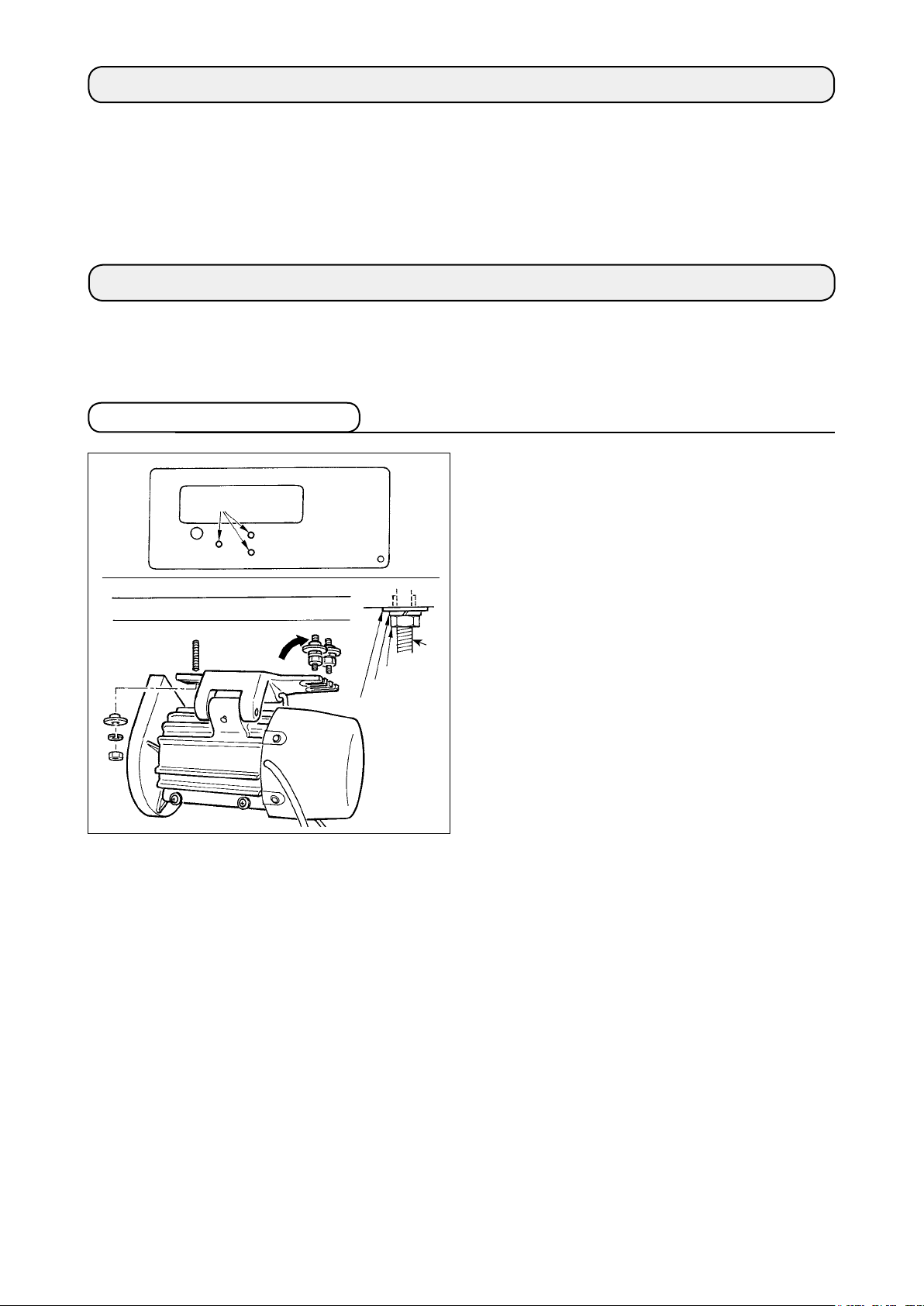
(1) Installing the motor unit
Install the motor unit on the table with the tting bolt
(asm.) supplied with the unit as accessories.
❶
❶
❹
❸
❷
At this time, insert the nuts and washers supplied
with the unit as accessories as shown in the gure
so that the motor unit can be securely xed on the
table.
1) Press three bolts
accessories into the motor hanging bolt hole in
the table and x them.
2) Temporarily tighten convex washer
washer ❸ and nut ❹ on the side where two bolts
are attached.
3) Hang the motor unit to the washer which has
been temporarily tightened, and attach convex
washer ❷, spring washer ❸ and nut ❹ to the
other bolt on the opposite side.
4) After adjusting the installing position of the motor,
securely tighten the respective nuts ❹.
supplied with the unit as
❶
, spring
❷
– 1 –
Page 4
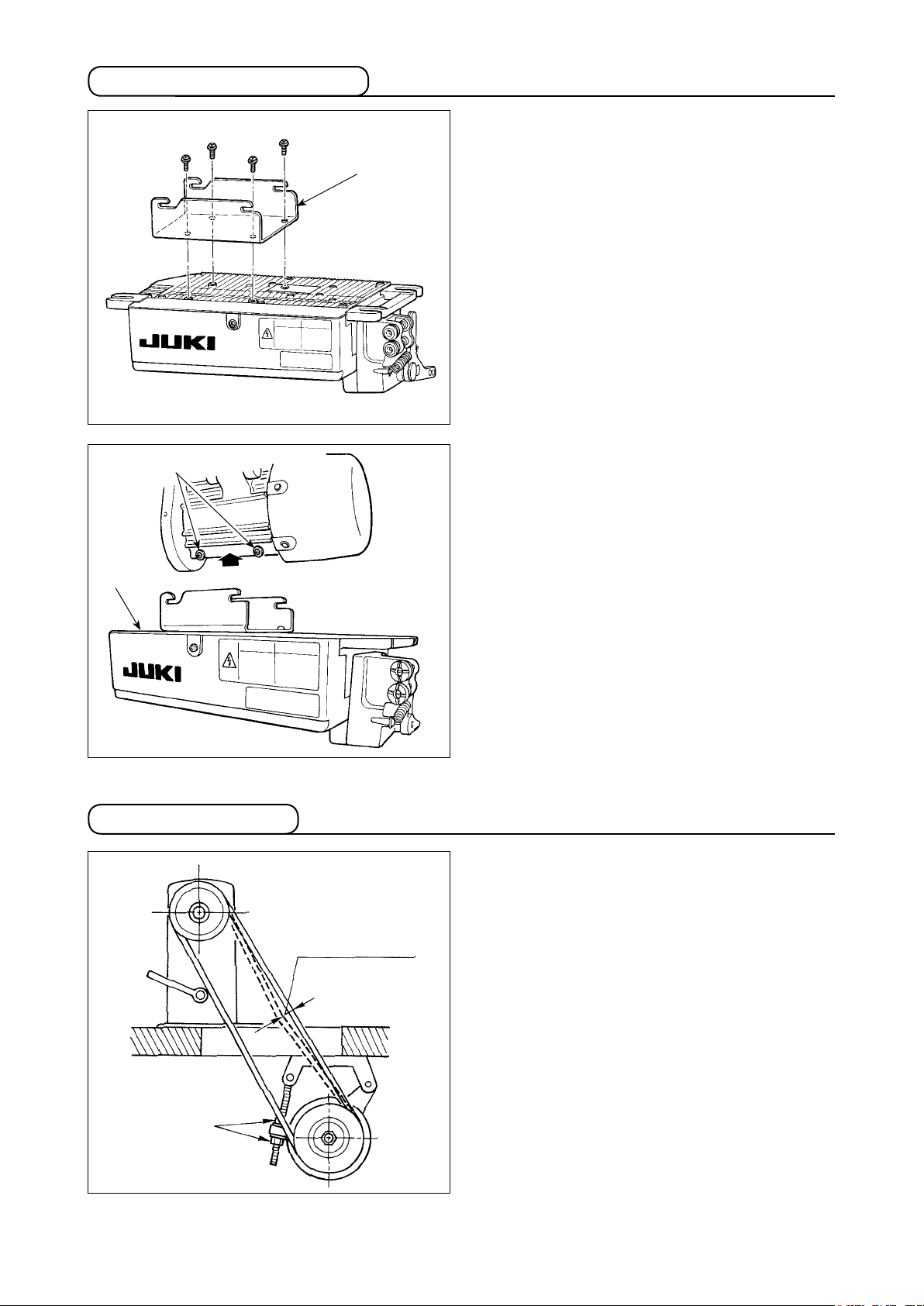
(2) Installing the control box
❷
❶
1) Attach bracket
four supplied screws (M5 × 10) as shown in the
gure.
2) Loosen four screws
tor unit as accessories, tighten screws ❷ after
hanging control box unit ❸ to the screws, and x
control box unit ❸.
supplied with the unit using
❶
supplied with the mo-
❷
❸
(3) Installing the belt
15 mm (9.8N)
1) The belt distance, between sewing machine pul-
ley and motor pulley, must be parallel.
2) The belt tension should be adjusted by turning
the tension adjust nuts ❶ to change height of the
motor, so that the belt sinks down by about 15
mm (9.8N) when it is depressed by band at the
center of the belt span.
If the belt tension is not tight, speed is unstable
at low-speed or medium-speed operation, and
the needle will not stop exactly in position.
❶
– 2 –
Page 5
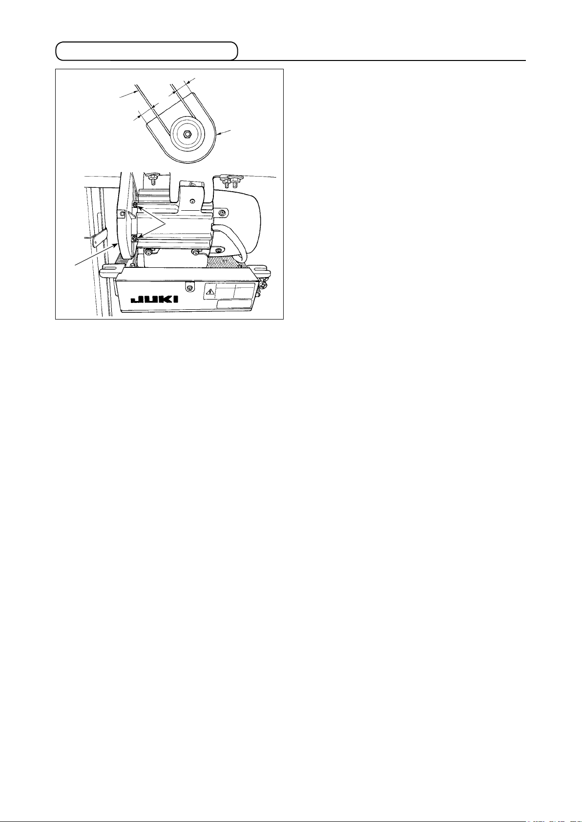
(4) Adjusting the pulley cover
❶
❸
b
❷
a
❶
1) After adjusting the belt tension, adjust the pulley
cover ❶ so that the clearances between the belt
and the pulley cover ❶, a and b should be
❸
the same.
2) After the completion of adjustment, tighten screws
located on the side of pulley cover ❶ and
❷
securely x the pulley cover ❶ so that it does not
slip out of position.
– 3 –
Page 6
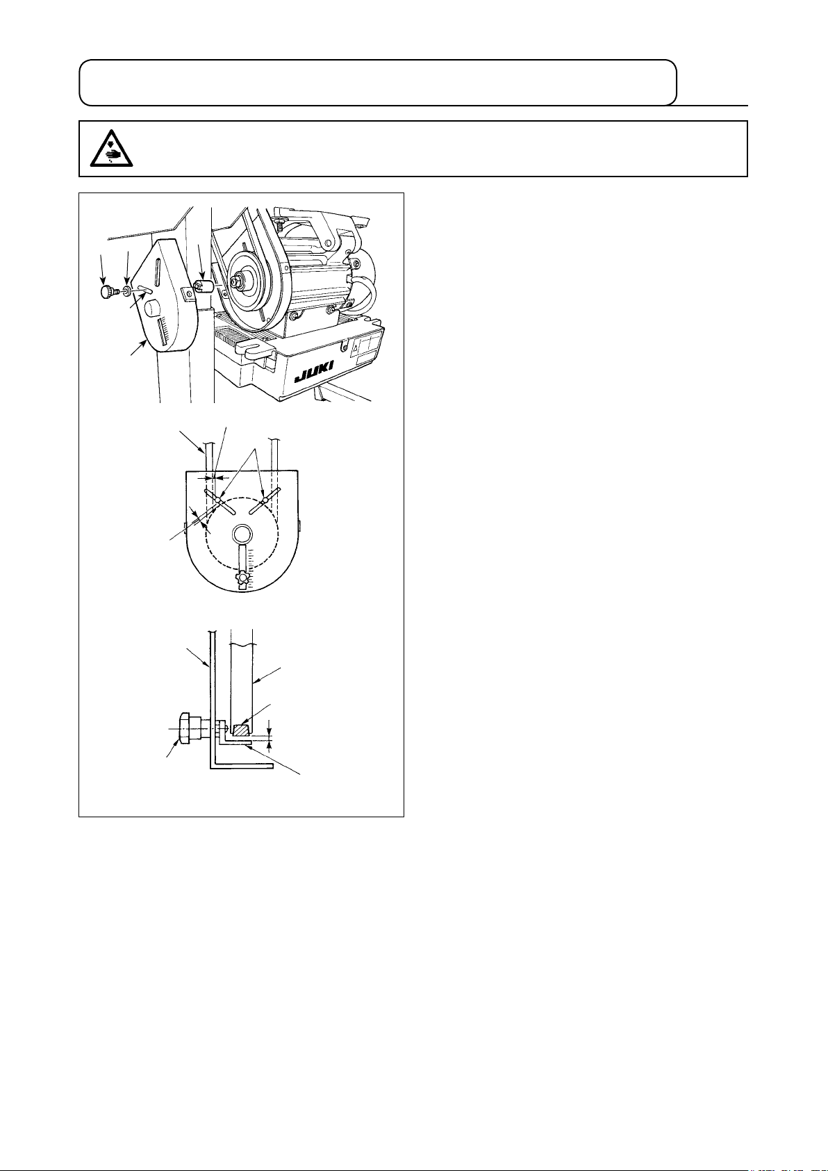
(5) Installation and adjustment for the protecting pin and the belt slip-off
preventing bracket
WARNING :
To protect against possible personal injury due to abrupt start of the machine, be sure to start the
following work after turning the power off and ascertaining that the motor is at rest.
1) Attaching hole for the protecting pin
Fit protecting pin ❶ in mounting hole A of motor
❷
❸
❶
pulley cover ❽ with accessory screw ❷ and
washer ❸ supplied with the unit.
A
❽
4 mm or less
❻
❶
4 mm or less
Adjusting position for protecting pin
❽
❻
❼
2) Adjustment for the protecting pin and the belt
slip-off preventing bracket
Adjust the position of protecting pin ❶ and belt
slip-off preventing bracket ❹ in accordance with
the gure on the left.
a) Adjusting the protecting pin
Loosen screw ❷ and adjust so that protecting
pin ❶ is positioned at the location indicated in
the gure on the left.
b) Adjusting belt slip-off preventing bracket
Loosen screw ❺ and adjust so that belt slip-
off preventing bracket ❹ is positioned at the
location indicated in the gure on the left.
If protecting pin ❶ is not properly adjusted, it
is possible that your ngers may be caught in
the clearance provided between the pulley ❼
and the belt ❻ resulting in injury.
If belt slip-off preventing bracket ❹ is not
properly adjusted, it is possible to allow the
belt ❻ to slip off causing safety hazard.
3 mm or less
❺
❹
Adjusting position for belt slip-off preventing bracket
3) After the adjustment, tighten screws ❷ and ❺
so as to secure protecting pin ❶ and belt slip-off
preventing bracket ❹ to prevent these compo-
nents to uctuate because of vibration.
4) Before starting the operation of the sewing
machine, ascertain that protecting pin ❶ and
belt slip-off preventing bracket ❹ do not come in
contact with the pulley ❼ and the belt ❻.
– 4 –
Page 7
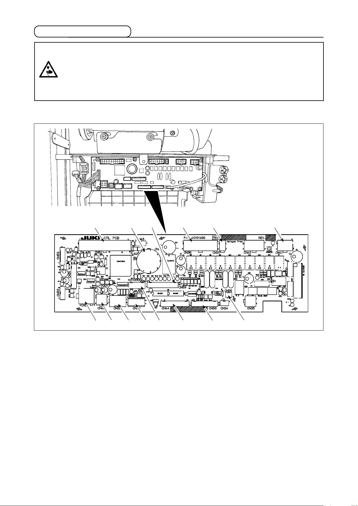
(6) Connecting the cords
WARNING :
• To prevent personal injury caused by abrupt start of the sewing machine, carry out the work after
turning OFF the power switch and a lapse of 5 minutes or more.
• To prevent damage of device caused by maloperation and wrong specifications, be sure to
connect all the corresponding connectors to the specied places.
• To prevent personal injury caused by maloperation, be sure to lock the connector with lock.
• As for the details of handling respective devices, read carefully the Instruction Manuals supplied
with the devices before handling the devices.
Following connectors are prepared on the SC-922. Connect the connectors coming from the machine head
to the corresponding places so as to t the devices mounted on the machine head.
❷
❶
CN30 Motor signal connector
❶
CN33 Needle bar position detector (+5V type): It
❷
❺ ❻
detects the needle bar position.
CN36 Machine head solenoid: Provided with
❸
solenoids for thread trimming, reverse
feed stitching, one-touch type reverse feed
switch.
CN37 Presser foot lifting solenoid (Only for the
❹
automatic presser foot lifter type)
CN38 Operation panel: Various kinds of sewing
❺
can be programmed.
CN39 Standing machine pedal : JUKI standard
❻
PK70, etc. Sewing machine can be controlled with external signals.
CN41 Stepping motor: It is used only with the
❼
DLU-5494N-7.
CN43 Synchronizer (+12V type) : It detects the
❽
needle bar position.
CN44 Hand switch: Hand switch other than the
❾
touch-back switch.
❽
❸ ❹ ❼
❾
CN48 Safety switch (standard) : When tilting the
sewing machine without turning the power
OFF, the operation of the sewing machine
is prohibited so as to protect against danger.
OPTION switch: Input function can be
changed by changing over the internal
function with this switch.
CN51 Extended input/output connector
CN55 LED lamp (+5V type): The LED lamp
can be connected optionally. (Refer to
"Instruction Manual for SC-922" for how to
adjust the quantity of light.)
CN58 Top-feed amount origin detector (+5V
type): This detector detects the origin of the
top feed amount.
Extended input connector (for the sensor
input, etc.)
CN59 Extended output connector (for the sole-
noid valve output)
– 5 –
Page 8
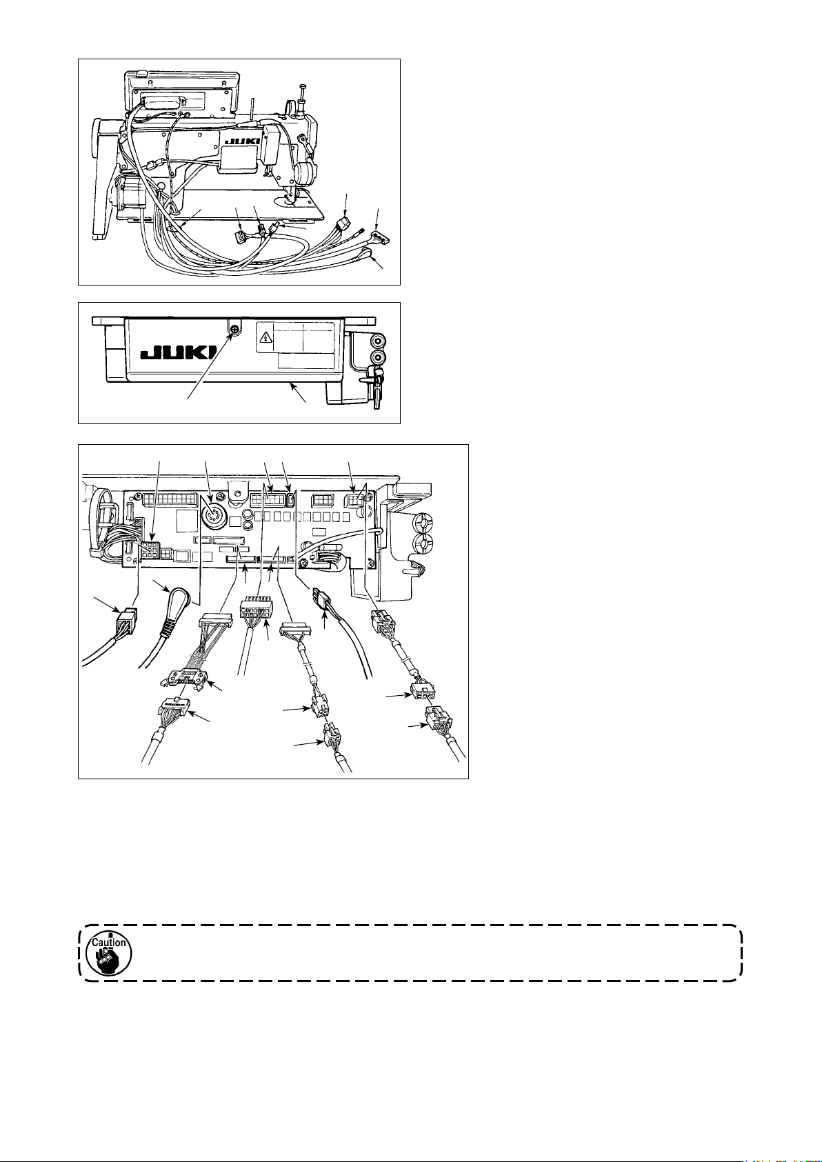
1) Pass through table hole
of thread trimer solenoid, reverse feed stitch-
❶
under the table cords
A
ing solenoid, etc., synchronizer cord ❷, IT panel
cord ❸, operation display panel cord ❹, top
feed detection cord ❺ and motor control cord ❻.
❷
❻
❹
A
B
❽
❶
❹
❺
❼
❺
❾
❶
❸
❷
2) Loosen screw
open the cover ❼.
❻
in cover ❼ with a screwdriver to
B
3) Connect 14P code
coming from
❶
the machine head to connector
(CN36).
When the optional AK device is
attached, connect 2P connector
coming from the AK device to con-
nector (CN37).
Insert connector
coming from the
❷
detector into connector (CN33).
Connect 9P connector
coming
from the motor to connector (CN30)
on the circuit board.
❽
❾
Relay 14P cord
coming from the operation display panel to sub-panel junction cord (asm.)
❹
(40148262) and insert the former into connector (CN44).
Relay top-feed detection 4P cord
to origin detector junction cord (asm.) (40148267) and insert the
❺
former into connector (CN58).
Relay 6P cord
coming from the stepping motor to stepping motor junction cord (asm.) (40148268)
❻
and insert the former into connector (CN41).
When using the AK device, set whether to use the AK device after conrming how to select the au-
to-lifter function. (Refer to "Instruction Manual for SC-922".)
– 6 –
Page 9
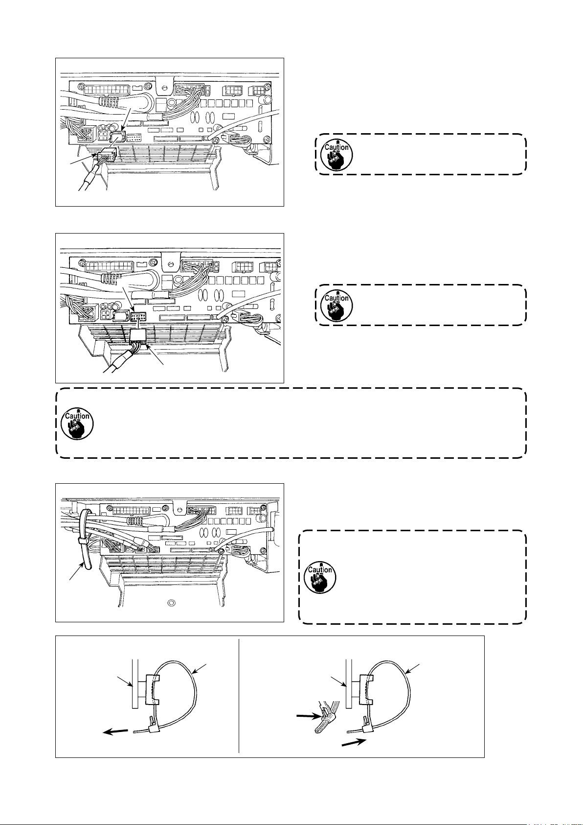
[Connecting the connector for the operation panel]
[Connection of the pedal of standing-work machine]
4) The connector for the operation panel is provided.
Paying attention to the orientation of the connec-
tor , connect it to connector (CN38) located
on the circuit board. After connecting, securely
lock the connector.
Be sure to turn OFF the power before
connecting the connector.
5) To use the pedal unit with the sewing machine
for standing work, insert PK70 connector into
connector (CN39: 12P) on the PCB.
Be sure to turn OFF the power before
connecting the connector.
Be sure to securely insert the respective connectors after checking the inserting directions since all
connectors have the inserting directions. (When using a type with lock, insert the connectors until
they go to the lock.) The sewing machine is not actuated unless the connectors are inserted properly.
In addition, not only the problem of error warning or the like occurs, but also the sewing machine and
the control box are damaged.
[How to bundle all cords]
How to x cable clip band
Panel
Pull
6) After inserting the connector, put all cords togeth-
er with cable clip band located on the side of
the box.
1. Fix the cord clamp and the cable clip
band following the attaching proce-
dure.
2. When removing the connector, remove it
from the wire saddle and remove it while
pressing the hook of the cable clip band
How to remove cable clip band
Panel
Push the hook.
Push
.
Pushing the
hook portion,
push the band
to remove it.
– 7 –
Page 10
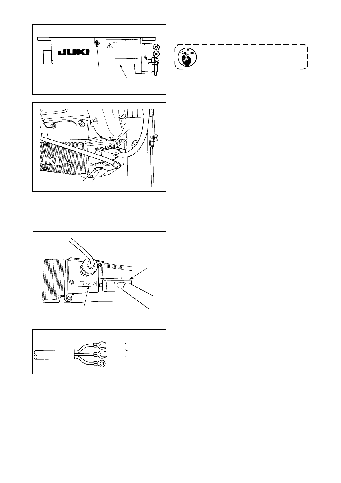
B
7) Close cover ❼ and x the cover by tightening
screw B with a screwdriver.
Take care not to allow the cord to be caught
under cover ❼.
❼
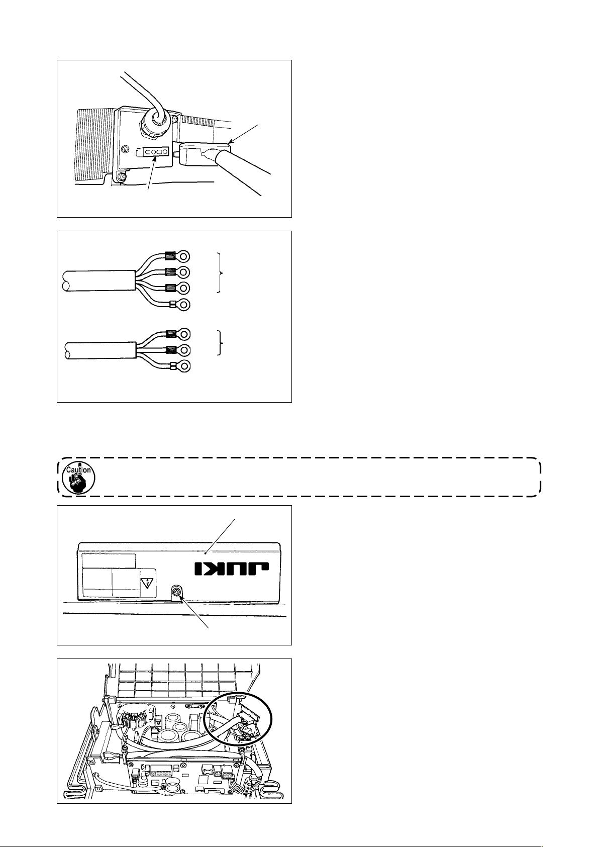
[For CE specications only]
8) Connect 4P connector to connector locat
on the side of the box.
9) Connect motor
outpu
t cord of the power
switch to connector .
Connect motor output cord to connector locat-
ed on the side of the box.
ed
CE 1ø 230V
Brown
Blue
Green / Yellow
(Ground wire)
AC 220V-240V
Installing power switch
Connect power supply cord to the power switch.
[CE specications]
Single phase 230V :
Power supply cords : Brown, Blue, and green/yellow
(ground wire)
– 8 –
Page 11
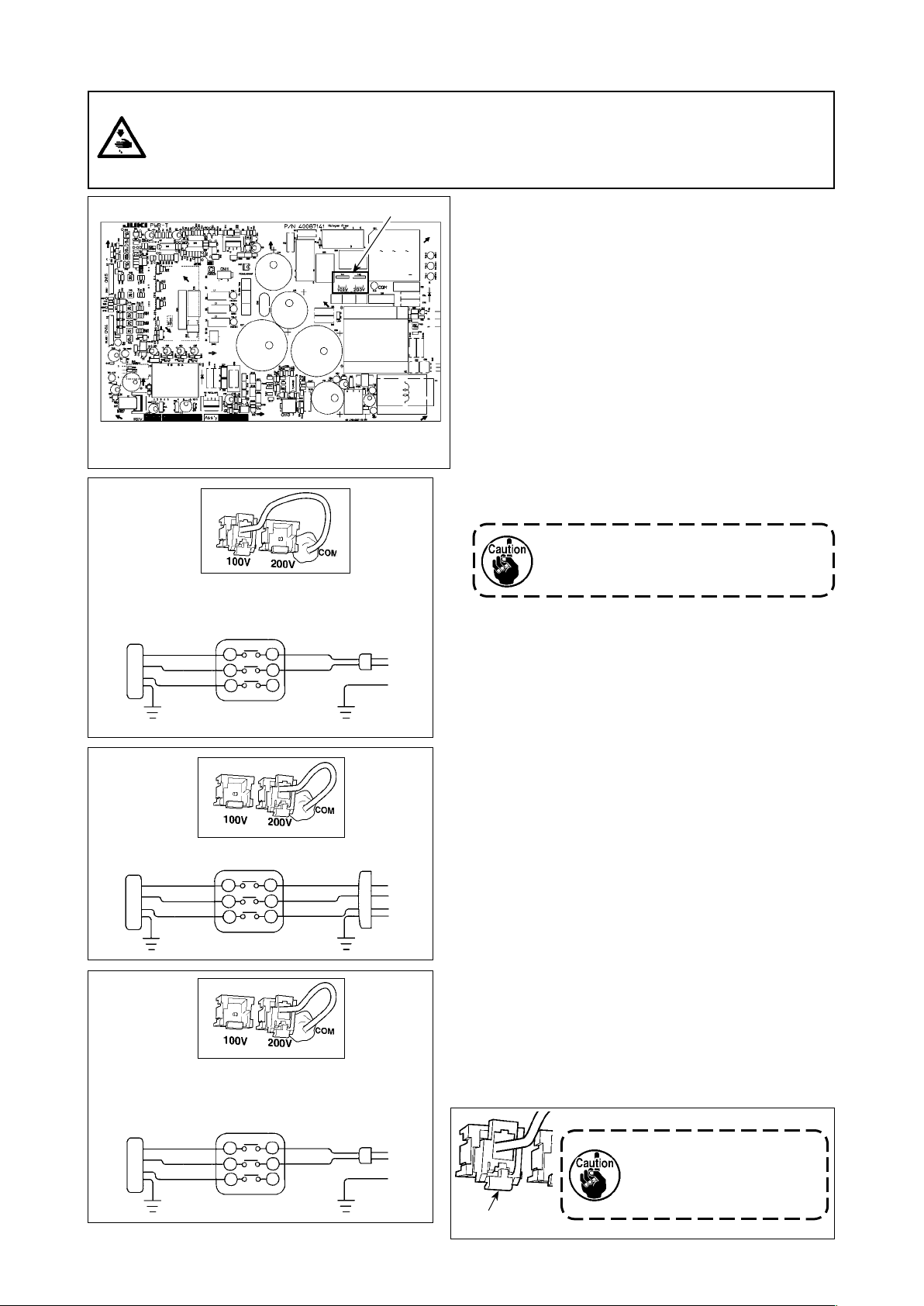
[Changing over the voltage between 100 V and 200 V]
WARNING :
To prevent personal injuries caused by electric shock hazards or abrupt start of the sewing machine,
carry out the work after turning OFF the power switch and a lapse of 5 minutes or more. To prevent
accidents caused by unaccustomed work or electric shock, request the electric expert or engineer of
our dealers when adjusting the electrical components.
* The illustration below shows the PWR-T PCB.
The type of PCB differs by destination.
A
Wiring for the single-phase 100 V
(Box side)
Be sure to connect the wire between 1 and 2.
If it is connected between 1-3 or 2-3, the sewing
machine will be inoperative.
WHITE
BLACK
RED
GREEN/
YELLOW
1
2
3
YELLOW
WHITE
BLACK
GREEN/
(Plug side)
B
Wiring for the 3-phase 200 V
(Box side)
WHITE
BLACK
RED
GREEN/
YELLOW
1
2
3
YELLOW
(Plug side)
WHITE
BLACK
RED
GREEN/
C
Wiring for the single-phase 200 V
(Box side)
Be sure to connect the wire between 1 and 2.
If it is connected between 1-3 or 2-3, the sewing
machine will be inoperative.
WHITE
BLACK
RED
GREEN/
YELLOW
1
2
3
YELLOW
WHITE
BLACK
GREEN/
(Plug side)
By making the following two changes, the SC-922
can be used with three different power supplies, i.e.,
single-phase 100 - 120 V, single-phase 200 to 240 V
and 3-phase 200 to 240 V.
* Only the control box which uses PWR-T PCB can
be changed.
Replacement of the power cords
①
Changing-round of connector on the PWR PCB
②
1) Turn OFF the power with the power switch after
checking that the sewing machine has stopped.
2) Draw out the power cord from the power receptacle after checking that the power switch has
been turned OFF. Then wait for 5 minutes or
more.
3) Loosen the screws which are used to secure the
rear lid of the control box cover. Carefully open
the rear cover.
4) Changing procedure of the power voltage
If the supply power changing is carried out
in a wrong manner, the control box can
break. Be extremely careful when taking the
supply voltage changing procedure.
A. To change over the supply voltage from 200 -
240 V to 100 - 120 V
Change the power cord with the JUKI genuine cord
・
with the part number (M90355800A0). Change
the earth cord with the one with the part number
(M90345800A0).
Change over supply voltage changeover connector
・
mounted on the PWR PCB with the connector for 100 V.
Connect the crimp style terminal of AC input cord to
・
the power plug as shown in the gure A.
B,C. To change over the supply voltage from 100 -
120 V to 200 - 240 V
Change the power cord with the JUKI genuine cord
・
with the part number (M90175800A0).
Change over supply voltage changeover connector
・
mounted on the PWR PCB with the connector for 200 V.
Connect the crimp contact of the AC input cord to the
・
power plug as illustrated in Fig. B for the 3-phase power supply or as illustrated in Fig. C for the single-phase
one.
5) Before closing the rear lid of the cover, ascertain
again that the relevant parts have been correctly
changed without fail.
6) Close the read lid while pressing it, taking care not
to allow the wiring to be caught between the read lid
of the cover and the main body of the control box.
Then, secure the lid with the screws.
Be sure to remove the connector while holding its lock-
ing section with your ngers.
Be extremely careful not to
Locking section
pull the connector forcibly.
– 9 –
Page 12
[In case of using the power switch for LA]
JA 3ø 220V
JA 1ø 120V
Black
Red
White
Green / Yellow
(Ground wire)
Black
White
Green / Yellow
(Ground wire)
AC 200V-240V
AC 100V-120V
Connect motor output cord to connector locat-
ed on the side of the box.
Installing power switch
Connect power supply cord to the power switch.
[JA specications]
3-phase 220 V :
Power supply cords : black, white, red and green/
yellow (ground wire)
Single phase 120V :
Power supply cords : black, white, and green/yellow
(ground wire)
When the metallic conduit is used, be sure to change over the power cord section following the steps of procedure described below.
Be sure to carry out this procedure before installing the control box on the machine table.
Place the control box with its frame side down on
❼
①
the machine table as illustrated in the sketch.
Loosen screw
②
in underside cover ❼ to open
B
the cover.
B
Change over the cord shown in the red-line
③
circle following the steps of procedure described
below.
– 10 –
Page 13
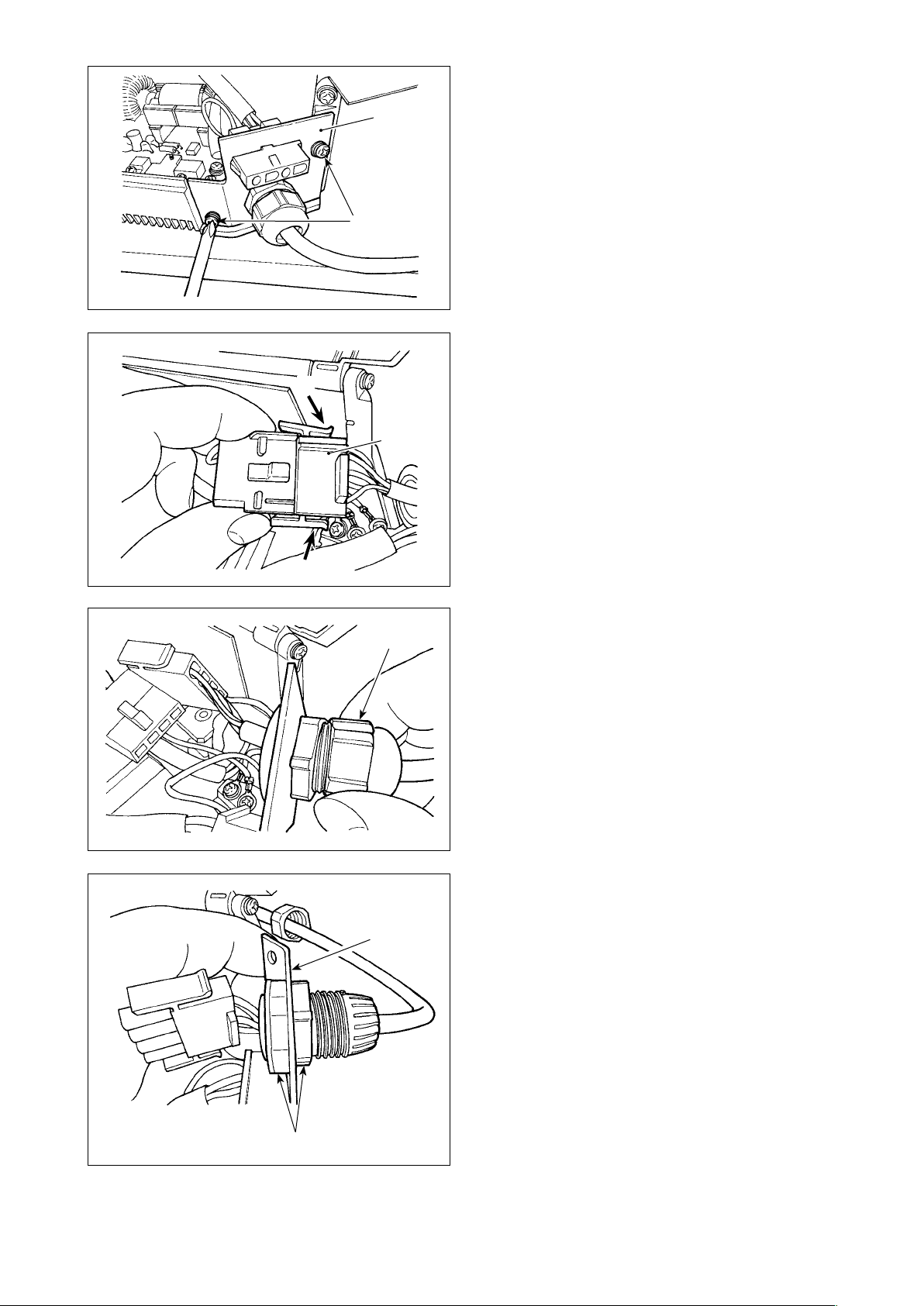
F
C
D
E
Remove two screws C to remove clamping plate
④
from the main body of the control box.
D
Remove connector E while holding its locking
⑤
section F with your ngers.
F
D
G
Turn connector G to remove the cord locking
⑥
section.
Loosen nut H to remove the connector from
⑦
clamping plate D.
H
– 11 –
Page 14
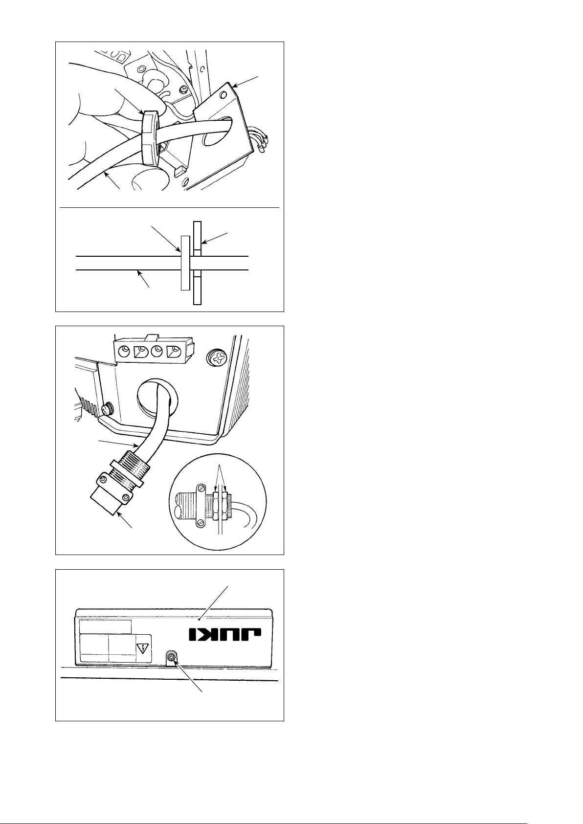
I
J
D
Put locknut I on the power cord and draw out
⑧
the cord J from inside clamping plate D.
J
I
J
I
D
Install clamping plate D back to the control box.
⑨
Pass power cord J through conduit K.
⑩
Fix conduit K with locknuts I with clamping
⑪
plate D placed between the locknuts.
K
B
❼
– 12 –
Close underside cover ❼ and secure the cover
⑫
with screw B.
Page 15
10) Make sure that the power switch is turned OFF
and insert power supply cord coming from the
power switch into the power plug socket.
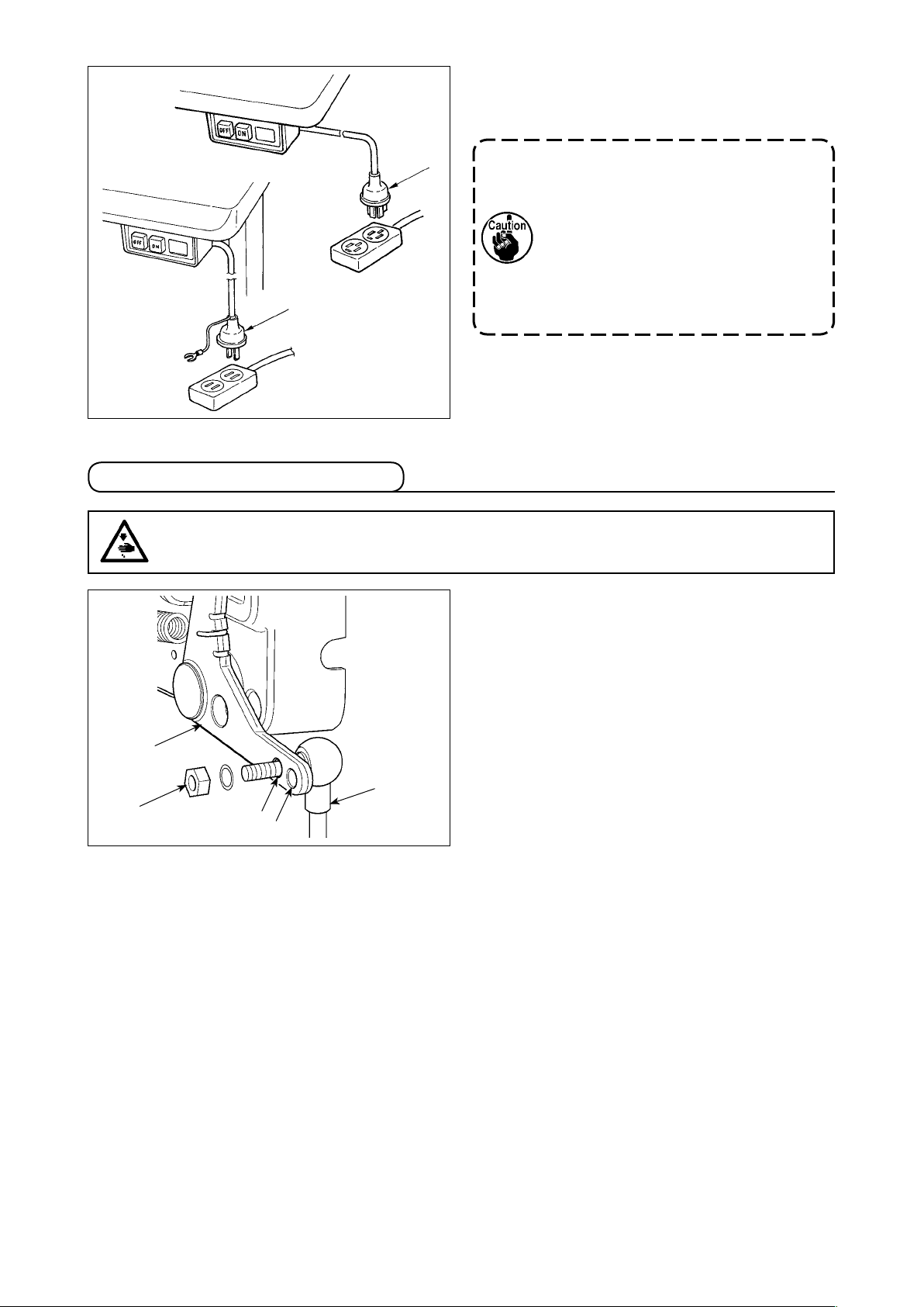
(7) Attaching the connecting rod
WARNING :
To protect against possible personal injury due to abrupt start of the machine, be sure to start the
following work after turning the power off and a lapse of 5 minutes or more.
1. Top end of power supply cord varies in
accordance with destination or supply
voltage. Check again the supply voltage
and the voltage designated on the con-
trol box when installing the switch.
2. Be sure to prepare power plug con-
formed to the safety standard.
3. Be sure to connect the ground wire (green
/ yellow).
1) Fix connecting rod ❶ to installing hole B of ped-
al lever ❷ with nut ❸.
2) Installing connecting rod ❶ to installing hole A
will lengthen the pedal depressing stroke, and
the pedal operation at a medium speed will be
easier.
❸
❷
B
❶
A
– 13 –
Page 16
(8) Installing the operation display panel
❸
❷
A
❶
❶
1) Fix operation display panel ❶ in tapped hole
in the rear section of the machine arm using
A
screw ❷ and washer ❸.
2) Attach operation display panel ❶ to the afore-
mentioned place so that it is in parallel to the bed
surface and does not come in contact with the
lower section of the machine arm.
Parallel to the bed surface
No contact
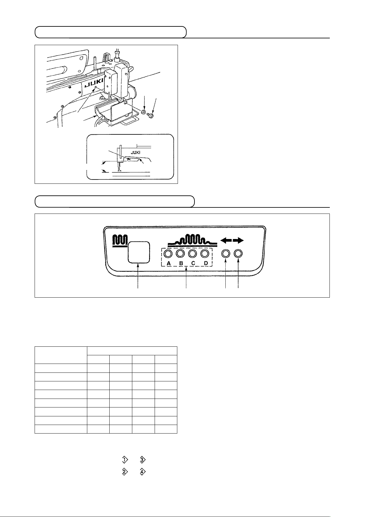
(9) How to use the operation display panel
• Operation
Partial shirring switch
❶
・ This is the switch used to change over the partial shirring process.
Indicator lamp (LED) of the partial shirring process step
❷
・ Indicates the current state of partial shirring process step.
indication panel
❶
❷
❸
❹
Partial shirring
process step
1
2
3
4
5
6
7
8
Partial shirring pattern indicator lamps (LEDs) under the alternate stitching mode
❸,❹
If partial shirring pattern or is selected under the alternate stitching mode, LED ❸ will light up.
・
Indicator lamp (LED)
A B C D
○ ● ● ●
○ ○ ● ●
○ ○ ○ ●
○ ○ ○ ○
● ○ ○ ○
● ● ○ ○
● ● ● ○
● ● ● ●
(Note)
……
○
……
●
Lights up
Goes out
If partial shirring pattern or is selected under the aforementioned mode, LED ❹ will light up.
If the machine is not operated under the alternate stitching mode, both LEDs ❸ and ❹ will go out.
・
– 14 –
Page 17

(10) Adjusting the bottom feed pitch display
When the display of the bottom feed pitch does not correspond with the scale of the pitch dial, perform the
setting below.
1) Adjust the scale of the bottom feed pitch dial to
"0".
2) Turn the variable resistor VR1 ❶ located on the
right side of the rear of the operation display
panel, and adjust so that the bottom feed display
is set to the minimum display.
3) Adjust the scale of the bottom feed pitch dial to
"5".
4) Turn the variable resistor VR2 ❷ located on the
right side of the rear of the operation display
panel, and adjust so that the bottom feed display
is set to "5.0".
❷
❶
VR2
VR1
3. INSTALLING THE OPERATION PANEL
WARNING :
To protect against possible personal injury due to abrupt start of the machine, be sure to start the
following work after turning the power off and ascertaining that the motor is at rest.
1) Attach operation panel ❶ to the machine head
2) Use B hole of bracket A as the operation panel
❶
❷
A
Type A (Type name plate TYPE A0*)
A
❹
❸
B
using screw ❷, plain washer ❸ and toothed
lock washer ❹ supplied with the operation panel.
mounting hole.
– 15 –
Page 18

4. HOW TO USE THE OPERATION PANEL
(1) Names and functions of each components
❶ ❹ ❺
❷
❸
Re-sewing switch
❶
Teaching switch
❷
Needle up/down compensating switch
❸
Screen changeover switch
❹
With/without reverse feed stitch at sewing start
❺
switch
With/without reverse feed stitch at sewing end
❻
switch
Material edge sensor switch
❼
One-shot automatic sewing switch
❽
❻
❼
❽
❾
With/without automatic thread trimmer switch
❾
Thread trimming prohibiting switch
Backlight switch
Reset switch
Information switch
+ switch
– switch
Counter/speed changeover switch
General-purpose switch
Power display lamp
Re-sewing switch
❶
Teaching switch
❷
Needle up/down com-
❸
pensating switch
Screen changeover
❹
switch
With/without reverse
❺
feed stitch at sewing
start switch
With/without reverse
❻
feed stitch at sewing
end switch
Edge sensor switch
❼
Switch Description
This switch is used to continue sewing from the step on the way
after replacing bobbin thread when bobbin thread has run out
during program stitching step.
This is the switch to set the setting of the number of stitches with
the value of number of stitches which has been actually sewn.
This is the switch to perform needle up/down compensating
stitching. (Needle up/down compensating stitching and one stitch
compensating stitching can be changed over with function setting
No. 22.)
This is the switch to change over the screen.
This is the switch to turn ON/OFF automatic reverse feed stitch at
sewing start.
* This switch cannot be used with the sewing machine which is not
provided with automatic reverse feed stitching device.
This is the switch to turn ON/OFF automatic reverse feed stitch at
sewing end.
* This switch cannot be used with the sewing machine which is not
provided with automatic reverse feed stitching device.
Selects use/disuse of the material edge sensor in the case the material edge sensor (edge) is installed on the sewing machine.
– 16 –
Page 19

Switch Description
One-shot automatic
❽
sewing switch
When this switch is pressed, the sewing machine automatically
operates until the material edge sensor detects the material edge
or until the set number of stitches is reached.
With/without automatic
❾
thread trimmer switch
This switch is used to automatically trim the thread when the material edge sensor detects the material edge or until the set number
of stitches is reached.
* This switch cannot be used with the sewing machine which is not
provided with the automatic thread trimming device.
Thread trimming prohib-
iting switch
This switch prohibits all thread trimmings.
* This switch cannot be used with the sewing machine which is not
provided with the automatic thread trimming device.
Backlight switch This switch is used to change over the operation of the backlight of
the LCD between ON and OFF.
Reset switch This is the switch to make the value of bobbin thread counter or
sewing counter the set value. This switch is enabled after thread
trimming.
Information switch This switch is used to change over the screen between the in-
formation function screen (sewing common data mode, function
setting mode, communication mode, version display, etc.) and the
normal sewing screen.
This switch is enabled after thread trimming.
Plus switch This switch is used to increase the set value of the bobbin thread
counter or the number of pcs. counter at the time of setting. It
should be remembered that this switch is enabled after thread
trimming.
Minus switch This switch is used to decrease the set value of the bobbin thread
counter or the number of pcs. counter at the time of setting. It
should be remembered that this switch is enabled after thread
trimming.
Counter/speed change-
over switch
This switch is used to change over the display between the counter display and the maximum sewing speed limitation display.
General-purpose switch This switch has different functions depending on the screen.
Power display lamp Lights up when the power switch is turned ON.
(2) Adjusting the contrast of the operation panel display
1) Press in the direction of arrow mark the click of
Light
❷
Shade
❸
❶
section A of cord outlet cover ❷ assembled in
the rear of operation panel ❶ and remove the
cover.
2) Turn LCD screen display brightness adjustment
variable resistor ❸ to adjust the brightness (con-
trast) of LCD screen.
1. To prevent the operation panel from
breakage, do not touch the circuit board
pattern and the connector terminal.
2. Do not disassemble the operation panel
to prevent it from breakage.
A
– 17 –
Page 20

(3) Production control switch connecting connector
1) Press in the direction of arrow mark the click of
section A of cord outlet cover ❷ assembled in
❸
❶
the rear of operation panel ❶ and remove the
cover.
2) Connect the optional relay cable connector to
CN105 ❸ of the production control switch con-
necting connector.
Prepare the switch main unit by the cus-
tomers or ask JUKI business ofce about
it.
❷
Optional relay cable A (asm.)
JUKI Part No. : 40008168
3 2 1
A
5V
+
SW
GND
CN105
1
2
3
(4) USB port
Precautions to be taken when handling USB devices
①
• Do not leave the USB device or USB cable connected to the USB port while the sewing machine is in
operation. The machine vibration can damage the port section resulting in loss of data stored on the USB
device or breakage of the USB device or sewing machine.
• Do not insert/remove a USB device during reading/writing a program or sewing data.
It may cause data breakage or malfunction.
• When the storage space of a USB device is partitioned, only one partition is accessible.
• Some type of the USB device may not be properly recognized by this sewing machine.
• JUKI does not compensate for loss of data stored on the USB device caused by using it with this sewing
machine.
USB specications
②
• Conform to USB 1.1 standard
• Format supported ������ FAT 32
• Consumption current ���� The rated consumption current of the applicable USB devices is 500 mA at the
maximum.
– 18 –
Page 21

5. SCREEN LIST
(1) Fundamental screen list
WELCOME screen is displayed immediately after turning ON the power.
The screen immediately after WELCOME screen becomes the pattern edit screen.
Every time switch is pressed, the screen changes.
Pattern edit screen
■
Step editing of the pattern is performed.
Number of stitches of back tuck stitching setting screen
■
Setting of number of stitches of reverse stitching is performed.
Pattern operation screen
■
Register, copy or deletion of the pattern is performed.
– 19 –
Page 22

Work management screen
■
On this screen, the contents of display related to the production support function and those called up by op-
erating the switches can be set or changed.
When the production support function is enabled under the information mode, the respective produc-
tion support function screens can be displayed by means of the screen changeover switch
the work management screen. For the details, refer to "II-2-2. Displays on the screen for the produc-
tion support function" of Instruction Manual for IT-100.
from
(2) Pop-up list
Pattern step insertion/deletion pop-up
■
Insertion/deletion of the step is performed.
Pattern register pop-up
■
Selection of the pattern to be registered is performed.
Pattern copy pop-up
■
Pattern of copy source or pattern of copy destination is selected.
– 20 –
Page 23

Pattern deletion pop-up
■
Pattern to be deleted is selected.
(3) Other screens
Pattern register screen
■
When DETERMINE key is pressed at the "pattern register pop-up" of (2) Pop-up list, this screen is dis-
played.
Register and edit of the pattern is performed in this screen.
– 21 –
Page 24

(4) Transition of screen
Pattern edit screen
Number of stitches of
back tuck stitching setting screen
Pattern operation screen
Pattern step insertion/deletion pop-up
Pattern deletion pop-up
Screen for the production support function
Pattern copy pop-up
Pattern register pop-up
Pattern register screen
– 22 –
Page 25

6. OPERATING PROCEDURE OF THE SEWING PATTERN
(1) Selecting procedure of the sewing pattern
As many as 16 patterns can be held as the sewing patterns.
❶
❷
When changing the pattern, change it with pattern change switches ❶ and ❷.
Change of the pattern can be performed not only in the step edit screen but also in the number of stitches of
back tuck stitching screen or the pattern operation screen.
(2) Editing procedure of the sewing pattern
Press switch to display the pattern edit screen.
❸
❷❶❹
and ❷ Number of stitches of the selected step is set.
❶
(Setting range : 0 to 500 stitches)
When 0 stitch is registered to the number of stitches, automatic update of the step by the number
of stitches is not performed. The step is manually changed over with the shirring step changeover
switch located at the jaw section of the machine head.
❺ ❻
and ❹ Shirring amount of the selected step is set.
❸
(Setting range : 0.0 to 8.0 mm)
and ❻ Selected step can be moved.
❺
– 23 –
Page 26

Example of the pattern
Step 3
20 stitches/3.5 mm
Editing procedure is shown
as an example in the pattern
on the left-hand side.
Step 2
10 stitches/3.0 mm
Step 1
10 stitches/2.0 mm
Number of stitches
Shirring amount
Step 4
18 stitches/3.0 mm
[Step 1]
1) Conrm that step 1 is selected, and set the number of stitches to 10 using switches ❶ and ❷.
2) Set the shirring amount to 2.0 using switches ❸ and ❹.
3) Select the next edit step using switches ❺ and ❻.
After editing step 1
■
❸
❺ ❻
❷❶❹
[Step 2]
4) Conrm that step 2 is selected, and set the number of stitches to 10 using switches ❶ and ❷.
5) Set the shirring amount to 3.0 using switches ❸ and ❹.
6) Select the next edit step using switches ❺ and ❻.
After editing step 2
■
❸
❺ ❻
❷❶❹
– 24 –
Page 27

[Step 3]
7) Conrm that step 3 is selected, and set the number of stitches to 20 using switches ❶ and ❷.
8) Set the shirring amount to 3.5 using switches ❸ and ❹.
9) Select the next edit step using switches ❺ and ❻.
After editing step 3
■
❸
❷❶❹
[Step 4]
10) Conrm that step 4 is selected, and set the number of stitches to 18 using switches ❶ and ❷.
11) Set the shirring amount to 3.0 using switches ❸ and ❹.
After editing step 4
■
❸
❺ ❻
❺ ❻
❷❶❹
– 25 –
Page 28

(3) Teaching mode
By using the teaching mode, it is possible to input the number of stitches of the step in a program with the
number of stitches that has been actually sewn.
Press switch to display the pattern edit screen.
❸
❹
<Teaching switch>
❶
1) In the pattern edit screen, press teaching switch ❶ to select the teaching mode.
2) The indication shown on the number of stitches input section changes to . This shows that the sewing
machine has entered the teaching mode.
3) Depress the front part of the pedal to make the sewing machine perform sewing until the last stitch of the
step. (Caution : the number of stitches is not inputted by manual turning or needle up/down compensating switch.)
4) Return the pedal to its neutral position to make the sewing machine stop running, and the number of
stitches which has been sewn is displayed.
5) Number of stitches can be corrected by pressing switches ❸ and ❹ in the state that the sewing machine
has stopped.
6) Proceed to the next step using switch ❷ or make the sewing machine perform thread trimming. This
completes the input of the number of stitches of step 1.
❷
(4) Selecting the sleeve to be sewn
One sewing pattern has the data on left sleeve and right sleeve.
Press switch to display the pattern edit screen.
❶
❷
In the pattern edit screen, changeover of data on left sleeve and those on right sleeve can be performed with
sleeve selection switches ❶ and ❷.
is displayed while left sleeve is being selected.
is displayed while right sleeve is being selected.
When "Without reference" is selected in the data creation reference of the pattern register, the sleeve
selection pictograph is not displayed.
– 26 –
Page 29

(5) Selection of the alternate sewing
There is the alternate sewing function that when performing thread trimming after completion of sewing of
one sleeve, the sewing automatically changes to the sewing of the other one.
Press switch to display the pattern edit screen.
❶
❷
Changeover of alternate sewing function ON/OFF can be performed with alternate sewing selection switches
and ❷.
❶
When the alternate sewing function is ON, is displayed.
When the alternate sewing function is OFF, is displayed.
When "Without reference" is selected in the data creation reference of the pattern register, the sleeve
selection pictograph is not displayed.
– 27 –
Page 30

(6) Insertion and deletion of the step
When any insufcient step or any unnecessary step occurs at the time of editing the pattern, insertion or de-
letion of the step can be performed.
Press
Step insertion/deletion pop-up
■
switch to display the pattern edit screen.
❷❶
❸
❹
❺
[Common operation]
1) Move the step to the position where you desire to insert or delete with step selection switches
2) Press step edit switch
3) When the step insertion/deletion pop-up is displayed by mistake or the insertion/deletion position is se-
lected by mistake, press cancel switch ❹.
[In case of insertion]
4) When step insertion switch
A new step is inserted at the selected position. The steps which are positioned at and after the selected
position respectively move backward.
[In case of deletion]
5) When step deletion switch
to display the step insertion/deletion pop-up.
❸
is pressed, insertion of the step is executed.
❺
is pressed, deletion of the step is executed.
❻
❻
and ❷.
❶
– 28 –
Page 31

(7) Operating procedure of the number of stitches of the reverse stitching
[Sewing pattern diagram]
❶
OFF ON OFF ON
A
B
A
B
Sewing pattern
C
D
❷
OFF OFF ON ON
C
D
[Operating procedure]
Press switch to display the number of stitches of reverse stitching setting screen.
❶
❸
❷
❹
1. When changing the number of stitches, change it with switches ❸ and ❹ for setting the number of stitch-
es A through D.
(The range of the number of stitches that can be changed : 0 to 99 stitches)
2. Press switch ❶ to set the reverse stitching at the start of sewing.
No setting Double reverse stitching
Reverse stitching at
the start of sewing
at the start of sewing
3. Press switch ❷ to set the reverse stitching at the end of sewing.
No setting
Reverse stitching at
the end of sewing
Double reverse stitching
at the end of sewing
– 29 –
Page 32

7. PATTERN OPERATION
Creation of the new sewing pattern, copy of the sewing pattern or deletion of the sewing pattern can be performed in the pattern operation screen.
(1) Sewing pattern register
Press switch to display the pattern edit screen.
❶
Press sewing pattern register switch ❶ in the sewing pattern operation screen.
When the information is registered to all patterns, the pattern register pop-up is not displayed.
Pattern register pop-up
■
❷ ❹ ❺
❸ ❺ ❼
and ❸ Pattern to be registered is set.
❷
and ❺ Data creation reference at the time of creating the pattern is set.
❹
References below can be selected.
Left reference
This is the cancel switch. Screen returns to the pattern operation screen.
❻
This is the determination switch. Screen moves to the pattern register screen.
❼
, Right reference , Without reference
The pattern which has been already registered cannot be selected.
– 30 –
Page 33

Pattern register screen
■
❶ ❸ ❺ ❻ ❾
❷ ❹ ❼ ❽
and ❷ Number of stitches of the step is set.
❶
and ❹ Shirring amount of the step is set.
❸
and ❻ Move of the step is performed.
❺
Step is inserted to the selected step.
❼
Selected step is deleted.
❽
Register is cancelled and the screen returns to the pattern operation screen.
❾
Determination of register of the set data is performed. At this time, the data which is inverted to the left or
right is automatically registered to the sleeve on the opposite side.
[Teaching mode]
Teaching mode can be used in the pattern register screen.
❷❸
❹
<Teaching switch>
❶
1. Press teaching switch ❶ in the pattern register screen, and select the teaching mode.
2. The indication shown on the number of stitches input section changes to . This shows that the sewing
machine entered the teaching mode.
3. Depress the front part of the pedal to make the sewing machine perform sewing until the last stitch of the
step.
(Caution : the number of stitches is not inputted by manual turning or needle up/down compensating
switch.)
4. Return the pedal to its neutral position to make the sewing machine stop running, and the number of
stitches which has been sewn is displayed.
5. Number of stitches can be corrected by pressing switches ❸ and ❹ in the state that the sewing machine
has stopped.
6. Proceed to the next step using switch ❷ or make the sewing machine perform thread trimming. This
completes the input of the number of stitches for step 1.
– 31 –
Page 34

(2) Copy of the sewing pattern
Press switch to display the pattern edit screen.
❶
Press sewing pattern copy switch ❶ in the sewing pattern operation screen.
When the information is registered to all patterns, the pattern copy pop-up is not displayed.
Pattern copy pop-up
■
❶
❷ ❹
and ❷ Pattern to be the pattern source is set.
❶
and ❹ Pattern to be the pattern destination is set.
❸
Copy is cancelled.
❺
Copy is executed.
❻
The pattern which has been already registered cannot be selected to the copy destination.
❸
❺
❻
– 32 –
Page 35

(3) Deletion of the sewing pattern
Press switch to display the pattern edit screen.
❶
Press sewing pattern deletion switch ❶ in the sewing pattern operation screen.
When the pattern which has been registered is one, the deletion pop-up is not displayed.
Pattern deletion pop-up
■
and ❷ Pattern to be deleted is set.
❶
Deletion is cancelled.
❸
Deletion is executed.
❹
❶
❷
❸
❹
– 33 –
Page 36

8. HOW TO USE THE BOBBIN THREAD COUNTER
The number of stitches sewn by the sewing machine is detected. The detected number of stitches is dec-
remented from the preset counter value (in units of the number of stitches preset using function setting No.
7 "Unit of bobbin thread counting down"). When the counter value changes from the positive value to the
negative value (...→ 1 → 0 → -1), the buzzer sounds (3 sets of two consecutive blips) and the notication is
shown on the pop-up window to alert the operator to change the bobbin.
❷ ❸
Initial value on the bobbin thread
counter for reference
1) Press counter/speed changeover switch
to change over
❶
the screen to the counter screen. Press switch ❷ to select the
bobbin counter. Then, press counter reset switch ❸ to return
❹
the bobbin counter display to the initial set value (set value at
the time of delivery is "0").
❺
The bobbin thread counter cannot be reset during sew-
ing. In this case, make the thread trimmer actuate once.
❶
2) Set an initial value using counter value setting switches
.
❺
The table below gives the initial setting values for reference when
the bobbin is wound with thread to the extent that the pinhole in
the outside of the bobbin case is reached as shown in the gure
on the left side.
Thread tension rate 100 %
Thread used
Polyester spun
thread #50
Cotton thread #50
Length of thread wound
round the bobbin
36 m 1200 (Stitch length : 3 mm)
31 m 1000 (Stitch length : 3 mm)
Value on bobbin thread
counter
* The aforementioned values actually vary depending on the
material thickness and sewing speed. Adjustment is necessary
according to the conditions of use.
❹
and
3) Once the initial value is specied, start the sewing machine.
4) When a minus value is shown on the counter, the buzzer peeps three times and the pop-up display ap-
pears, replace the bobbin thread.
Bobbin thread replacement warning pop-up
5) After the bobbin thread has been properly replaced, press counter reset switch
to return the value on
❸
the bobbin thread counter to the initial value. Now, re-start the sewing machine.
6) If the remaining amount of bobbin thread is excessive or the bobbin thread runs out before the bobbin
thread counter indicates a minus value, adjust the initial value appropriately using counter value setting
switches ❹ and ❺.
If the remaining amount of bobbin thread is excessive.....Increase the initial value using the “+” switch.
If the remaining amount of bobbin thread is insufcient....Decrease the initial value using “–” switch.
The remaining amount of thread may vary depending on how the thread is wound on the bobbin and
the material thickness. It is therefore better to set the remaining amount of thread with a slight allowance.
– 34 –
Page 37

9. NO. OF PCS. COUNTER
❷ ❸
Press counter/speed changeover switch ❶ to change over the
screen to the counter screen.
Press switch ❷ to select the sewing counter.
The sewing counter works as the thread trimming counter in the
❹
case the production volume management function of the IT-100 is
disabled, or works as the number of pcs. counter in the case the
❺
production volume management function is enabled.
When the sewing counter works as the thread trimming counter,
❶
the counter value can be corrected by means of counter-value
setting switches ❹ and ❺. In addition, the counter value is reset
to zero (0) by pressing counter reset switch ❸.
When the sewing counter works as the number of pcs. counter,
the counter value cannot be changed since the value displayed on
the counter is coupled with the production volume management
function.
Once the target production volume is reached under the teaching
mode on the pattern registration screen, its notication is given
when the target value of the counter is reached after the exit from
the pattern registration screen.
Refer to the Instruction Manual for the IT-100 for details of the
number of pcs. counter.
10. PRODUCTION SUPPORT FUNCTION
For the details, refer to "Instruction Manual for IT-100".
– 35 –
Page 38

11. BOTTOM FEED AMOUNT DISPLAY
Observation of the bottom feed amount is performed and the value is displayed on the panel. There are the
direct display and the ratio display for the way of display.
Direct display
■
❸
For the direct display, the bottom feed amount is displayed at bottom feed amount display section ❷, and
the set value is displayed at top shirring amount display section ❸. When switch ❶ is pressed, the display
changes to the ratio display.
Ratio display
■
❸
For the ratio display, 1.0 (xed display) is displayed at bottom feed amount display section ❷, and the value
that the top shirring amount is divided by the bottom feed amount is displayed at top shirring amount display
section ❸. When switch ❶ is pressed, the display changes to the direct display.
❶
❶
❷
❷
12. RE-SEWING SWITCH
For the details, refer to "Instruction Manual for IT-100".
13. NEEDLE UP/DOWN COMPENSATION SWITCH
For the details, refer to "Instruction Manual for IT-100".
– 36 –
Page 39

14. ON/OFF SWITCH OF THE MATERIAL EDGE SENSOR
❶
• When material edge sensor ❶ is pressed, ON/OFF of the material
edge sensor is changed over.
• When the material edge sensor, which is optionally available, is
connected to the operation panel, the ON/OFF switch of the materi-
al edge sensor becomes effective.
• If the material edge sensor is specied, the sewing machine will
automatically stop running or perform thread trimming when the
sensor detects the material edge.
If the material edge sensor is used in combination with the
operation panel, carefully read the Instruction Manual for the
material edge sensor beforehand.
15. AUTOMATIC THREAD TRIMMING SWITCH
• When automatic thread trimming switch ❶ is pressed, ON/OFF of
the automatic thread trimming is changed over.
• This is the switch which makes the sewing machine automatically
execute thread trimming when the material edge sensor is used.
(When the reverse stitching at the end of sewing is specied, the
thread trimming is performed after performing the reverse stitching
at the end of sewing.)
❶
16. ONE-SHOT AUTOMATIC STITCHING SWITCH
❶
• When one-shot automatic stitching switch ❶ is pressed, ON/OFF of
the one-shot automatic stitching is changed over.
• This is the switch which makes the sewing machine automatically
perform sewing at the specied speed until the material edge is
detected when the material edge sensor is used.
– 37 –
Page 40

17. THREAD TRIMMING PROHIBITION SWITCH
is pressed, ON/OFF of
❶
❶
• When thread trimming prohibition switch
the thread trimming prohibition is changed over.
• This switch is used to temporarily make the thread trimming function
inoperative.
The other performance of sewing machine is not affected by this
switch.
(If the automatic reverse stitching (for end) is specied, the sewing
machine will perform the automatic reverse stitching at the end of
sewing.)
• If the automatic thread trimming switch and the thread trimming
prohibition switch are both specied, the machine will not per-
form thread trimming but stop with its needle up.
18. KEY-LOCK FUNCTION SETTING
In order to prevent the programmed pattern from being edited by mistake, it is possible to activate the key-
lock function.
Once the key-lock function is activated, the number of stitches of a step, insertion/deletion of an edit step of
shirring amount and the pattern operation (registration, copy and deletion) will be disabled. In addition, edit of
processes (A, B, C and D) will also be disabled.
Refer to the Instruction Manual for the IT-100 for how to set the key-lock function.
– 38 –
Page 41

19. INFORMATION
Setting and checking of various data can be performed with the information.
For the information, there are the operator level and the maintenance personnel level.
(1) Information operator level
<Information switch>
❶
1. Turn ON the power.
2. Press switch ❶ to display the information screen.
❶
Sewing common data
❶
Sewing management information
❷
Time setting
❸
1) Sewing common data
❸ ❺ ❼
❶
❷ ❹ ❻ ❽
and ❷ Shirring smoothing function setting is performed.
❶
and ❹ Smoothing shirring pitch setting is performed.
❸
and ❻ Smoothing shirring offset setting is performed.
❺
and ❽ Stepping motor origin position setting is performed.
❼
and Number of remaining stitches of the step setting is performed.
❾
Setting is completed.
Pattern data mirroring function is performed.
❷ ❸
❾
– 39 –
Page 42

[Explanation of the respective functions]
1. Shirring smoothing function setting
ON/OFF setting of smoothing (shirring between the steps is smoothly changed over) function is per-
formed.
Smoothing function ON ......... is displayed.
Smoothing function OFF ....... is displayed.
2. Smoothing shirring pitch setting
This function is used to set the amount of top-feed pitch change per stitch when carrying out smoothing.
Setting range is 0.0 to 8.0 [mm].
3. Smoothing shirring offset setting
Offset of the 1st stitch is set when performing the smoothing. Setting range is 0 to 9.
Set value 1 2 3 4 5 6 7 8 9
Ratio to enter 1st stitch 10% 11% 12% 14% 17% 20% 25% 33% 50%
* When offset is set to "0", the smoothing function does not work.
* "Ratio to enter rst stitch" is the ratio in terms of the difference of shirring amounts between the steps.
* From the second stitch and beyond, the top-feed pitch will change by the amount of top-feed change
set with the smoothing shirring pitch setting function on a stitch-by-stitch basis.
4. Stepping motor origin position setting
Origin compensation of the stepping motor which determines the shirring amount is performed.
Setting range is –2.5 to 2.5 [mm].
The motor may fail to properly work. Any person other than the service engineer should not operate
the motor.
5. Number of remaining stitches of the step display function
This is the function to display the number of remaining stitches of the number of stitches of the step
which is currently being sewn as against the number of stitches which has been set.
When this function is used, the display is updated every time the sewing machine stops (excluding during
the teaching mode).
Number of remaining stitches display function ON ........ is displayed.
Number of remaining stitches display function OFF ....... is displayed.
– 40 –
Page 43

6. Pattern data mirroring function
Mirroring (data inversion) processing of the pattern which has been already registered is performed.
❶
❸ ❺
❷ ❹ ❻
and ❷ Pattern to which mirroring is executed is set.
❶
and ❹ Sleeve to be the reference of mirroring is set.
❸
Mirroring from left sleeve to right sleeve...... is displayed.
Mirroring from right sleeve to left sleeve...... is displayed.
Mirroring processing is cancelled.
❺
Mirroring processing is executed.
❻
The pattern to which mirroring has been performed here is selected as the current pattern.
7. Completion of setting
Setting of the common data is completed and the screen returns to the information screen.
2) Sewing management information
For the details, refer to "Instruction Manual for IT-100".
3) Time setting
For the details, refer to "Instruction Manual for IT-100".
– 41 –
Page 44

(2) Setting for functions
1) How to change over to the function setting mode
For the details, refer to "Instruction Manual for IT-100".
2) Function setting list
For the details, refer to "Instruction Manual for IT-100".
3) Communication mode
For the entering procedure to the communication mode, refer to the item of “Information maintenance per-
sonnel level” of Instruction Manual for IT-100.
The matters below can be performed in the communication mode.
1. Parameter data (EPD) from the media can be overwritten to the sewing pattern and registered.
2. Sewing pattern can be uploaded to SU-1 or the media.
■
Communication setting screen
❶
❷ ❻❸
Example of download
Example) Parameter le No. 70 of the media is downloaded to the sewing pattern No. 10.
Open the media cover and insert USB thumb drive from the inserting opening.
①
Selection of data
②
EPD is selected from the beginning since the data of EPD form only is handled for DLU-5494.
Selection of communication method
③
Press ❷ in the communication setting screen to display the communication method setting screen.
– 42 –
Page 45

Communication setting screen
■
❶❺❷ ❸ ❹
[Explanation of the pictograph]
❶ : Down load from the media
❷ : Download from SU-1
❸ : Upload to the media
Communication method
which is selected at present
is shown in reverse video.
❹ : Upload to SU-1
Press ❶ to select download from the media. Then press ❺ to determine.
Selection of le No. of the media
④
Press ❸ in the communication setting screen to display the le No. of media input screen.
– 43 –
Page 46

File No. input screen
■
❷
❷
❶❸
Input le No. of the media at ❷. The le No. which has been inputted is displayed in . The No. is deter-
mined with ❶ after inputting the le No.
Custom pattern No. setting
⑤
Press ❹ and ❺ in the communication setting screen to set the custom pattern No.
Communication setting screen
■
❹
❺ ❻
Start of download
⑥
When all setting procedures have been completed, press ❻ in the communication setting screen to start
downloading.
– 44 –
Page 47

During communication screen
■
When the screen returns to the communication setting screen after display of the during communication
screen, communication is completed.
Example of upload
Example) Sewing pattern No. 8 is uploaded as the parameter form le No. 15 of the media.
Open the media cover and insert USB thumb drive from the inserting opening.
①
Selection of data
②
EPD is selected from the beginning since the data of EPD form only is handled for DLU-5494.
Selection of communication method
③
Press ❷ in the communication setting screen to display the communication method setting screen.
[Explanation of the pictograph]
Download from the media
❶
Download from SU-1
❷
Upload to the media
❸
Upload to SU-1
❹
Press ❸ in the communication setting screen and press ❺ to determine after selecting upload to the
media.
Setting of the custom pattern No.
④
Press ❹ and ❺ in the communication setting screen to set the custom pattern No.
Selection of le No. of the media
⑤
Press ❸ in the communication setting screen to display the le No. of media input screen.
Input the le No. of the media. The inputted le No. is displayed in .
After inputting the le No., determine it with ❶.
Start of the upload
⑥
When all setting procedures have been completed, press ❻ in the communication setting screen to start
uploading.
– 45 –
Page 48

Communication setting screen
■
❹ ❶
❺ ❸ ❷ ❻
When the screen returns to the communication setting screen after display of the during communication
screen, communication is completed.
[How to delete the le of media]
After selecting No. you desire to delete in the le No. of media input screen, press switch of ❸. Then the
screen moves to the deletion conrmation screen.
Deletion conrmation screen
■
❶
❷
Press ❶ and the deletion is discontinued. Then the screen returns to the le No. input screen.
Press ❷ and the deletion is executed. Then the screen returns to the le No. input screen.
The deleted le is not restored. Be very careful when executing the deletion.
– 46 –
Page 49

(3) External interface
External interface means the section to connect the operation panel and the system which is different from
the operation panel.
For the use and details, refer to the Engineer's Manual.
1. Media slot
Media slot is installed in the face cover located on the right side of operation panel.
2. Ethernet port
An Ethernet connector is installed in the face cover located on the right side of operation panel.
3. RS-232C port
RS-232C connector is installed in the rubber cap located on the back side of operation panel.
4. General input port (Production control switch connecting connector)
General input connector, CN105 is installed in the cord outlet cover located on the back side of operation
panel.
20. ERROR DISPLAY
There are two different kinds of errors, those output from the operation panel and those from the SC-
922 (control box). Both kinds of errors are notied by the error screen and the buzzer.
Two different kinds of screens of the panel display screen appear due to the difference of the procedures.
1) Press the reset switch, and remove the cause of error after eras-
ing the error screen.
2) Remove the cause of error after turning OFF the power.
– 47 –
Page 50

(1) Error code list (Error display in panel)
There are the following error codes in this device. These error codes interlock (or limit function) and inform
the problem so that the problem is not enlarged when any problem is discovered. When you request our ser-
vice, please conrm the error codes.
No.
E000 Execution of data initial-
E003 Disconnection of syn-
E004 Synchronizer lower posi-
E005 Synchronizer upper
E007 Overload of motor • When the machine head is locked.
E008 Undened machine
E011 Media is not inserted.
E012 Read error
E013 Write error
E014 Write protect
E015 Format error
E016 External media capacity
E019 File size over
E032 File interchangeability
E041 Sewing recorder error
E044 Date and time error • This error number is displayed in
E053 Notication of produc-
E055 Production management
E056 Work management error • This error number is displayed in
Description of error
detected
ization (This is not the
error.)
chronizer connector
tion sensor failure
position sensor failure
head is selected
over
error
tion support function
initialization (This is not
an error)
error
Cause of occurrence expected Items to be checked
• When the machine head is
changed.
• When the initialization operation is
executed.
• When position detection signal is
not input from the sewing machine
head synchronizer.
• When the synchronizer has broken.
• Belt is loose.
• Machine head is not proper.
• Motor pulley is not proper.
• When sewing extra-heavy material
beyond the guarantee of the machine head.
• When the motor does not run.
• Motor or driver is broken.
• The machine head that does not
support the SC-922 is selected.
• Media is not inserted. • Turn the power OFF and check the
• Data of media cannot be read. • Turn the power OFF and check the
• Data of media cannot be written. • Turn the power OFF and check the
• Media is in the state of writing prohibition.
• Formatting cannot be performed. • Turn the power OFF and check the
• Capacity of media is short. • Turn the power OFF and check the
• File is too large. • Turn the power OFF and check the
• There is no interchangeability of
le.
• This error number is displayed in
the event of a sewing recorder data
fault.
the event of operation/data fault
concerning date or time of day.
• This error number is displayed after
the execution of initialization of the
production support function or upgrading of the program.
• This error number is displayed in
the event of production management work management data fault.
the event of data fault.
• Check the synchronizer connector
(CN33) for loose connection and disconnection.
•
Check whether the synchronizer cord
has broken since the cord is caught in
the machine head.
• Check the belt tension.
• Check the setting of the machine
head.
• Check the setting of the motor pulley.
• Check whether the thread has been
entangled in the motor pulley.
• Check the motor output connector (4P)
for loose connection and disconnection.
• Check whether there is any holdup
when turning the motor by hand.
• Check the machine head selection
using function setting No. 95.
• Check the Revision of the PWR PCB.
If it is Rev. 01, replace the PWR PCB
with the one revision of which is Rev.
02 or later.
media.
media.
media.
• Turn the power OFF and check the
media.
media.
media.
media.
• Turn the power OFF and check the
media.
• Check whether the data has any fault.
• Check whether the data has any fault.
• Check whether the data has any fault.
• Check whether the data has any fault.
– 48 –
Page 51

No.
E057 Pitch time monitor error
E065 Network transmission
E067 ID reading failed
E070 Slip of belt • When the machine head is locked.
E071 Disconnection of motor
E072 Overload of motor at the
E204 USB insertion • This message is displayed in the
E205 Warning of ISS buffer
E220 Grease-up warning • When the predetermined number of
E221 Grease-up error
E302 Fall detection switch
E303 Semicircular plate sen-
E499 Simplied program data
Description of error
detected
failed
output connector
time of thread trimming
motion
remaining amount
failure
(When the safety switch
works)
(Thread trimming knife
sensor)
sor error
fault
Cause of occurrence expected Items to be checked
• This error number is displayed in
the event of pitch time monitor data
fault.
• This message is displayed in the
case data cannot be sent to the
personal computer by way of the
network.
• This message is displayed in the
case data in the ID le is broken.
• Belt is loose.
• Disconnection of motor connector • Check the motor output connector for
• Same as E007 • Same as E007
case the sewing machine is activated with the USB thumb drive
inserted.
• This message is displayed in the
case the buffer storage for storing
the ISS data is almost full.
If the sewing machine is continuously used with the buffer storage
full, the stored pieces of data will be
erased from the earliest one.
stitches has been reached.
• When the predetermined number of
stitches has been reached and the
sewing is not possible.
• When fall detection switch is input
in the state that the power is turned
ON.
• Machine-head tilt detector's connecter has come off.
• Thread trimming knife position is
not correct.
• Semicircular plate sensor signal
cannot be detected.
• Command parameter data is out of
specied range.
• Check whether the data has any fault.
• Check whether the network has any
fault.
• Check whether the data has any fault.
• Check whether there is any holdup
when turning the motor by hand.
• Check the belt tension.
loose connection and disconnection.
• Remove the USB thumb drive.
• Output the data.
• Replenish the specied places with
grease and reset.
(For the details, refer to the data of the
machine head.)
• Replenish the specied places with
grease and reset.
(For the details, refer to the data of the
machine head.)
• Check whether the machine head is
tilted without turning OFF the power
switch (sewing machine operation is
prohibited for safety sake).
• Check whether the fall detection
switch cord is caught in the sewing
machine or the like.
• Check whether the fall detection
switch lever is caught in something.
• Check whether the contact of the tilt
detection switch lever with the machine table is inadequate. (The table
has a dent or the mounting location of
the bed strut is too far)
• Check the machine-head tilt detector's
connector (CN48) for looseness and
slip-off.
• Positioning of the thread trimming
sensor
• Set the function setting No. 74 to 0
(zero) when the thread trimmer is not
installed on the sewing machine.
• Check whether the machine head
corresponds with the machine type
setting.
• Check whether the motor encoder
connector is disconnected.
• Re-enter the relevant simplied program.
• Set the simplied program in disable.
– 49 –
Page 52

No.
E703 Operation panel is
E704 System version mis-
E730 Encoder failure
E731 Motor hole sensor failure
E733 Inverse rotation of motor
E799 Thread trimming opera-
E808 Solenoid short circuit
E809 Holding motion failure
E810 Solenoid current abnor-
E811 Abnormal voltage • When voltage higher than guaran-
E906 Operation panel trans-
E924 Motor driver failure
E942 Faulty EEPROM • Data cannot be written on the EE-
Description of error
detected
connected to the unexpected sewing machine.
(Error of sewing machine model)
match
tion time-out
mality
mission failure
Cause of occurrence expected Items to be checked
• The operation panel and the sewing
machine model do not match in the
initial communication.
• The system version is different from
the correct one in the initial communication.
• When the motor signal is not properly inputted.
• This error occurs when the motor
is running at 500 sti/min or more
in the opposite direction of that of
rotation indication during motor is
running.
• The thread trimming control operation is not completed within the
predetermined time (within three
seconds).
• Solenoid power does not become
normal voltage.
• Solenoid is not changed over to
holding motion.
• Solenoid rare short-circuit. • Solenoid resistance
teed one is inputted.
• 200V has been inputted to SC-922
of 100V specications.
• JA : 220V is applied to 120V box.
• CE : 400V is applied to 230V box.
• When voltage lower than guaranteed one is inputted.
• 100V has been inputted to SC-922
of 200V specications.
• JA : 120V is applied to 220V box.
• Inner circuit is broken by the applied overvoltage.
• Disconnection of operation panel
cord
• Operation panel has broken.
• Motor driver has broken.
PROM.
• Connect the operation panel to the
correct model of the sewing machine.
• Re-write the system version to the one
that can be used with the operation
panel.
• Check the motor signal connector
(CN30) for loose connection and disconnection.
• Check whether the motor signal cord
has broken since the cord is caught in
the machine head.
• Check whether the inserting direction
of the motor encoder connector is
wrong.
• Check whether the machine head
corresponds with the machine type
setting.
• Check whether the main-shaft motor
encoder wire is connected incorrectly.
• Check whether the main-shaft motor
wire for power supply is connected
incorrectly.
• Check whether the machine head
actually installed is different from the
machine head selection.
• Check whether the motor-pulley diameter does not match its setting (effective diameter).
• Check whether the belt has slackened.
• Check whether the machine head
cord is caught in the pulley cover or
the like.
• Check whether the solenoid is abnormally heated. (CTL circuit board asm.
Circuit is broken.
• Check whether the applied power voltage is higher than the rated voltage +
(plus) 10% or more.
• Check whether 100V/200V changeover connector is improperly set.
In the aforementioned cases, POWER
p.c.b is broken.
• Check whether the voltage is lower
than the rated voltage - (minus) 10%
or less.
• Check whether 100V/200V changeover connector is improperly set.
• Check whether fuse or regenerative
resistance is broken.
• Check the operation panel connector
(CN38) for loose connection and disconnection.
• Check whether the operation panel
cord has broken since the cord is
caught in the machine head.
• Turn the power OFF.
– 50 –
 Loading...