

JUKI LZ-2290 Series, CP-760, SC-905, LZ-2290SS, LZ-2290SS-7 Manual Manual
...
ENGINEER’S MANUAL
29345808
No.01
Direct-drive, Computer-controlled, High-speed, 1-needle,
Lockstitch, Zigzag Stitching Machine
LZ-2290 Series
CP-760 / SC-905

− 1 −
1. SPECIFICATIONS
(1) Specifications of the machine head
* 1 : The sewing speed is regulated in accordance with the destination at the time of delivery. (Zigzag width is
also regulated.)
* 2 : Zigzag width is regulated to 8 mm at the time of delivery. (Max. 10 mm is only for 2-step and 3-step zigzag
machines.)
* 3 : Normal and reverse feed amounts are regulated to 2 mm at the time of delivery.
Model
Application
Max. sewing speed
Max. zigzag width
Max. feed amount
(Normal/reverse)
Stitch pattern
Needle
Dimension of the bed
Number of revolution
of resistor pack
Needle bar stroke
Bobbin winder
Wiper (WB only)
Automatic reverse
stitching
Lubrication
Lift of the presser foot
(by hand lifter)
Lift of the presser foot
(by knee lifter)
Lift of the presser foot
(by AK auto-lifter)
Kind of the hook
(Part No.)
Bobbin case (asm.)
Height of the feed dog
Lubrication of the face
plate section
Drive system
Transmission function
Motor output
Operating power
Solenoid drive power
Additional function
Device and optional
1
2
3
4
5
6
7
8
9
10
11
12
13
14
15
16
17
18
19
20
21
22
23
24
25
26
27
Light- to medium-weight materials
10 mm (*2)
8 kinds 14 patterns (Custom pattern : 64 stitches, 8 kinds can be stored.)
SCHMETZ 134UK, 438, ORGAN DPX5 : #65 to #90
178 mmX517 mm
4,000 rpm (Excluding a certain territory of export)
33.4 mm
Built-in in the upper face of machine head type (with bobbin thread retaining plate)
Electromagnetic front-wiping system
Built-in electromagnetic system
5.5 mm
10 mm
6 to 6.5 mm
Direct drive system (compact AC servo motor)
Timing belt system
Rated output 450W
3-phase 200V, Single phase 100V
DC34V
Presser foot micro-lifting screw is provided as standard.
AK-121 (auto-lifter device)
500 g tin of exclusive grease for maintenance (Part No. : 23640204)
Touch-back kit (asm.) (Part No. : 23546658)
LZ-2290SS / –7
5,000 rpm (*1)
5 mm/4 mm (*3)
(Stepless fine adjustment)
1.2 mm
LZ-2290SU / –7
4,500 rpm (*1)
2.5 mm/2.5 mm (*3)
(Stepless fine adjustment)
1.4mm
LZ-2290DS / –7
5 mm (*3)
(Stepless fine adjustment)
1.2 mm
LZ-2290DU / –7
2.5 mm (*3)
(Stepless fine adjustment)
1.4mm
Lubrication system to oil tank for hook
lubrication
JUKI New Defrix Oil No. 1 is used.
(Equivalent to ISO VG7)
Plunger pump is employed.
22525877
23537350 (with idle-prevention spring)
Minute quantity lubrication by oil wick
Full non-lubrication
23557259 (Non-lubrication hook)
23557556 (with idle-prevention spring)
Non-lubrication
4,000 rpm (*1)
− 2 −
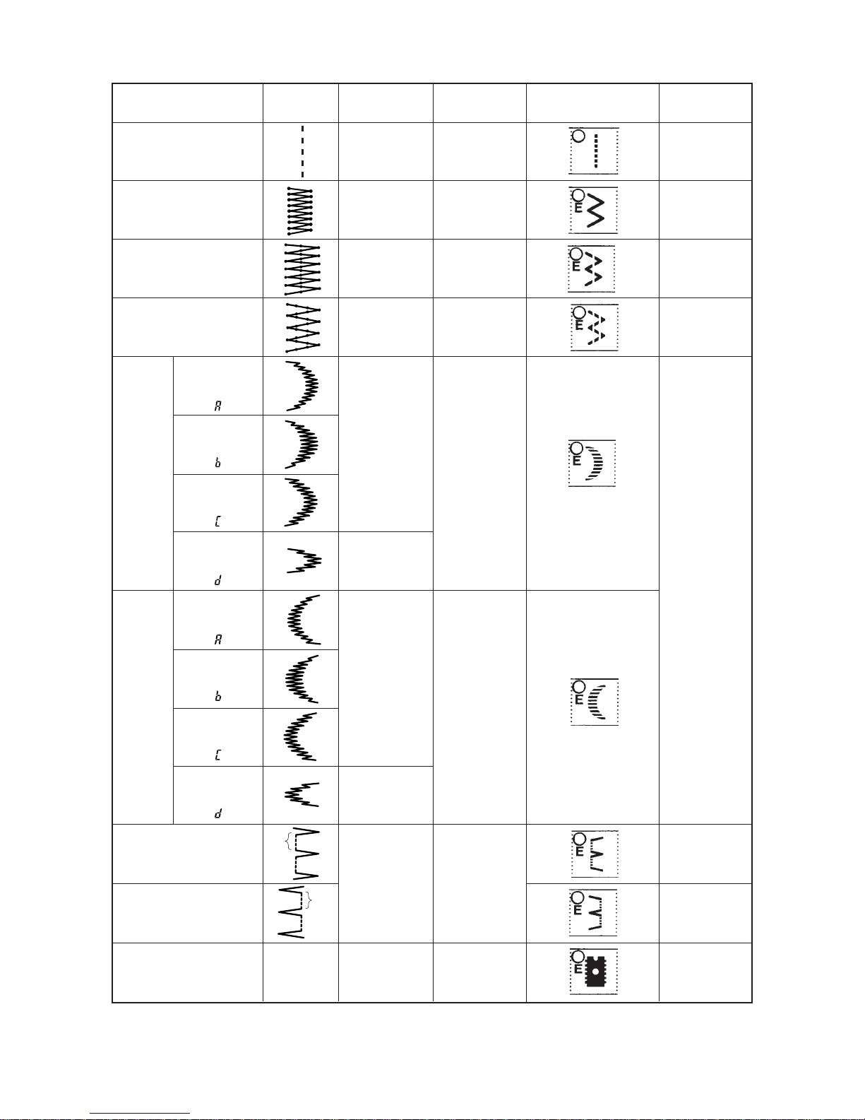
(2) Stitch pattern table
Straight stitch
Standard zigzag stitch
2-step zigzag stitch
3-step zigzag stitch
Scallop
(right)
Scallop
(left)
Blind stitch (right)
Blind stitch (left)
Custom pattern
Number of stitches
for pattern
Max. zigzag width
Pattern selection key Remarks
Scroll can be
performed by
pressing again.
Standard
scallop
Crescent
scallop
Equal-width
scallop
Equal-width
scallop
Standard
scallop
Crescent
scallop
Equal-width
scallop
Equal-width
scallop
1
2
4
6
24
12
24
12
2+a
–
8
10
10
8
8
8
10
–
Name of pattern Stitch pattern
Up to 64
a
a
( )
(
)
(
)
(
)
(
)
(
)
(
)
(
)

− 3 −
(3) Cautions in operation
1) Be sure to drain oil in the oil tank and attach the air vent cap (red rubber cap) supplied with the machine
to the air vent (golden bushing) located on the side face of the machine bed when transporting the
sewing machine.
2) In the case where placing SS or SU type machine on a stand or the like before setting the machine to
the machine table, to protect the oil tank from damage, take care if there is any protruding object under
the stand or the like.
3) Be sure to securely set the connector of the safety switch to the control box to prevent accidents at the
time of maintenance.
4) Oil is kept in the gear box for lubrication. It is not necessary to replace the oil. Do not remove the gear
box cover except when it is necessary.
* When the box cover has been removed, it is necessary to replace the packing.
5) Be sure to operate the sewing machine with the bobbin case removed when making the sewing machine
run idle.
If the bobbin thread is in the bobbin case, the thread protrudes from the bobbin case and is entangled
in the hook race or the hook shaft. As a result, the trouble will be caused.
− 4 −
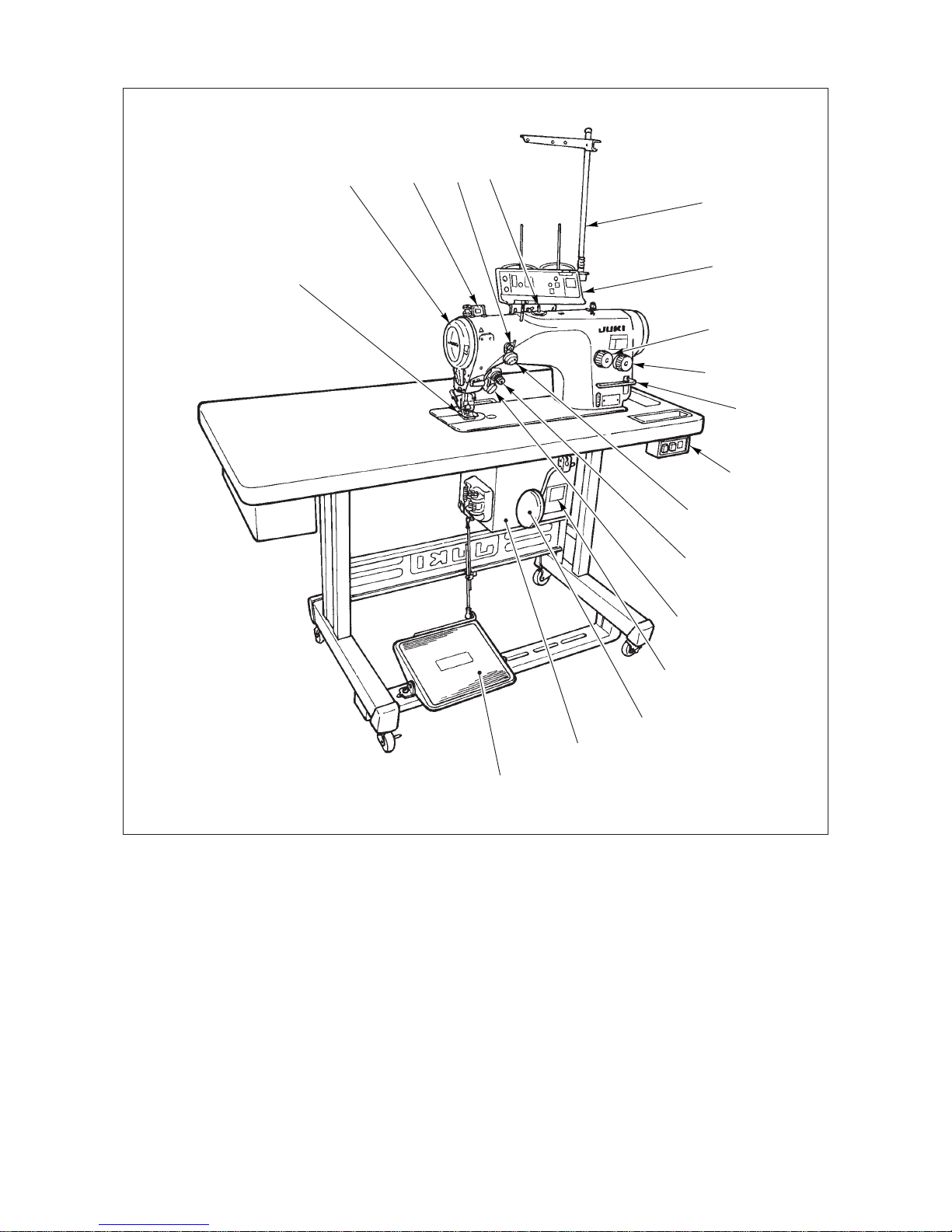
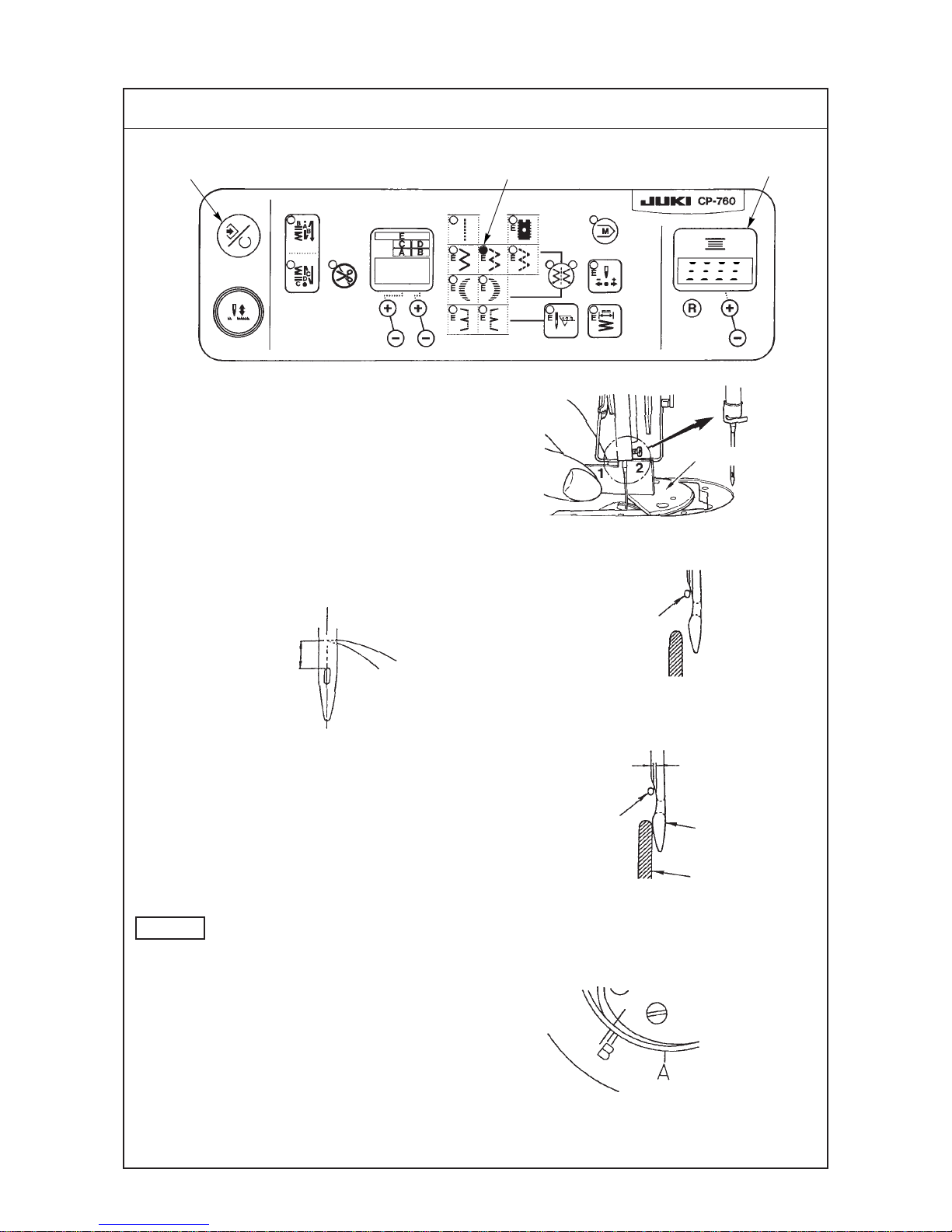
2. NAME OF EACH COMPONENT
1 Needle thread draw-out device 8 Knee lifter lever !5 Tension controller No. 1
2 Wiper evice 9 Power switch !6 Thread stand
3 Thread take-up cover !0 Hand switch !7 Setting display section
4 Finger guard !1 Stitch length dial !8 Reverse feed stitching lever
5 Thread tension controller !2 Condensation dial
6 Control box !3 Control panel
7 Pedal !4 Bobbin winder
1
2
3
4
5
6
7
8
9
!0
!1
!2
!3
!4
!5
!6
!7
!8

− 5 −
1 Needle thread draw-out device
This device draws out needle thread at the time of thread trimming.
2 Wiper device
This device wipes needle thread after thread trimming from the cloth by means of the wiper signal which
is output from the PSC box.
3 Thread take-up cover
This is a cover to protect the human body from the contact with the thread take-up.
4 Finger guard
This is a guard to protect the human body (mainly fingers) from the contact with needle.
5 Thread tension controller
6 Control box
This box contains circuit to control sewing machine and motor, output circuits to activate respective
outputs (thread trimming solenoid, reverse feed stitching solenoid, etc.), pedal sensor to detect pedal
action, and power circuit to activate respective functions.
7 Pedal
This pedal performs sewing machine speed control, thread trimming action, presser lifting action (for
AK118 only), etc. by operation of depressing the front part of pedal or the back part of pedal.
8 Knee lifter lever
9 Power switch
This is the power switch for motor, PSC, operation panel, etc.
!0 Hand switch
This is an operation switch to perform reverse feed stitching, inverting of scallop pattern, etc. by means
of the manual switch.
!1 Stitch length dial
!2 Condensation dial
!3 Control panel
This panel is used for setting automatic reverse feed stitching, pattern stitching, zigzag width, etc.
!4 Bobbin winder
This is a bobbin winder which is built in the machine head.
!5 Tension controller No. 1
!6 Thread stand
!7 Setting display section
!8 Reverse feed stitching lever
−6 −
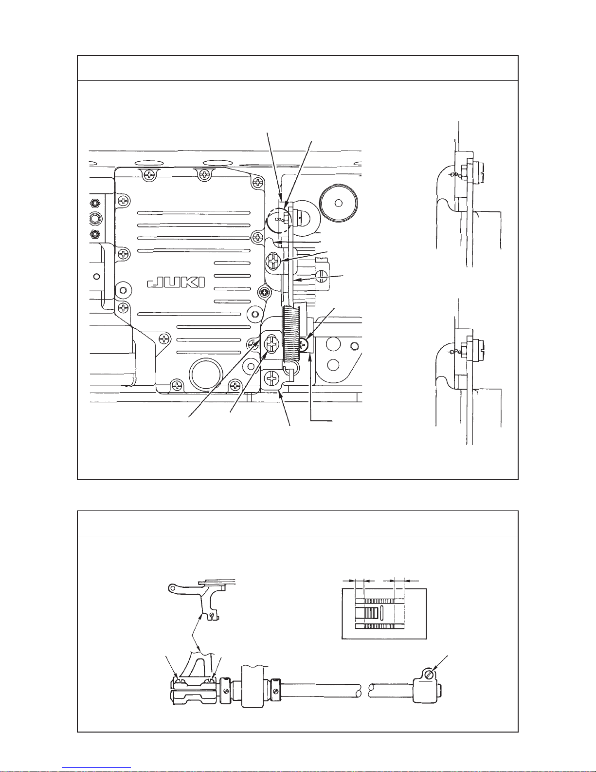
3. STANDARD ADJUSTMENT
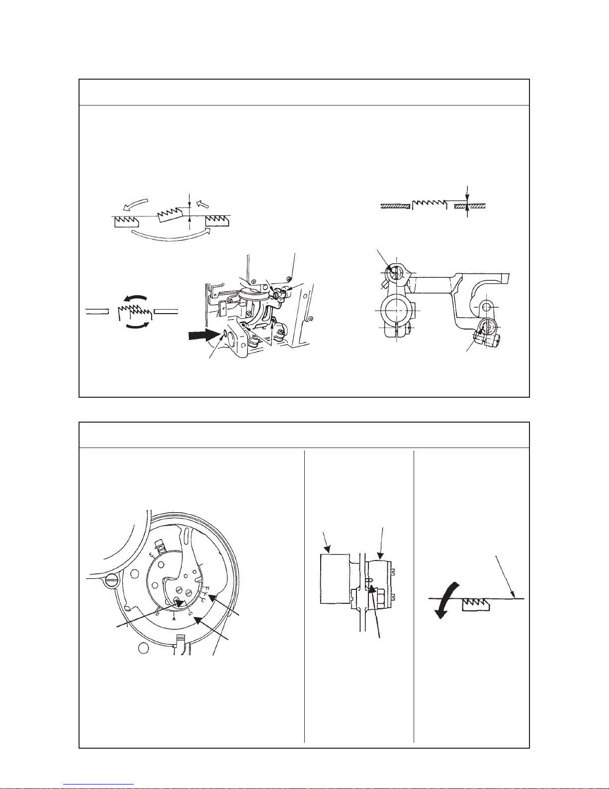
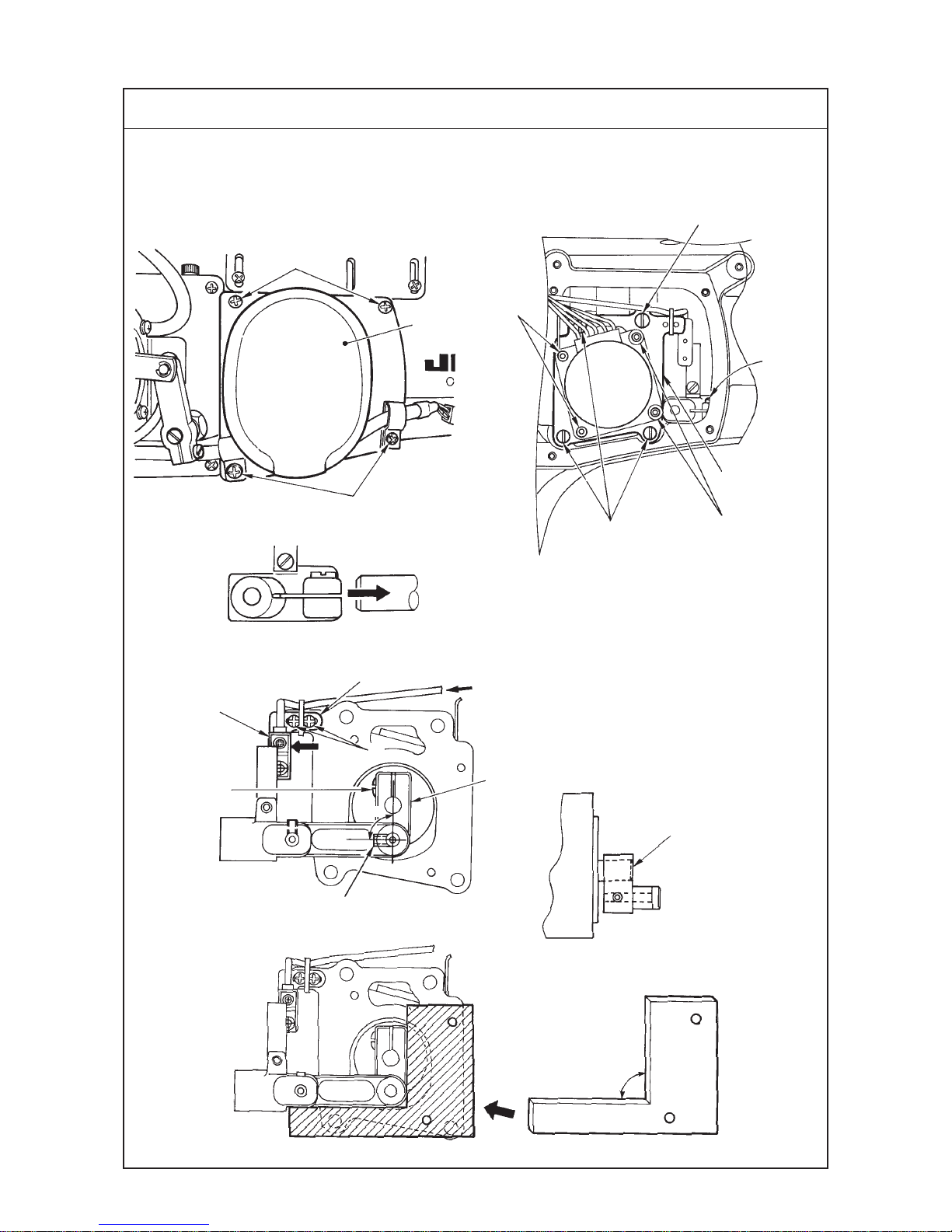
(1) Height and inclination of the feed dog
Standard Adjustment
(2) Adjusting the feed timing
Standard Adjustment
A B
Standard height : 1.2 mm : LZ-2290SS, LZ-229DS
: 1.4 mm : LZ-2290SU, LZ-2290DU
Inclination : The feed dog should be almost leveled
when the top surface of the ascending feed
dog is flush with the top surface of the
throat plate.
Reference for the height and inclination of the
feed dog
™ When the respective marker dots are
leveled, the height is 1.2 mm and the
inclination is leveled.
Timing mark F
engraved on
face plate
Feed rocker
cam
Feed
rocker rod
Alignment of
timing marks
Timing mark G
engraved on
face plate
Marker line
engraved on
thread takeup
1.2 mm
Throat plate
Feed dog
Hole for
screwdriver
Top suface of
throat plate
Comes down.
1.2 mm
LeveledLeveled
Operator’s
side
Position of marker dot
(Inclination)
Position of marker dot
(Height)
1
2
3

−7 −
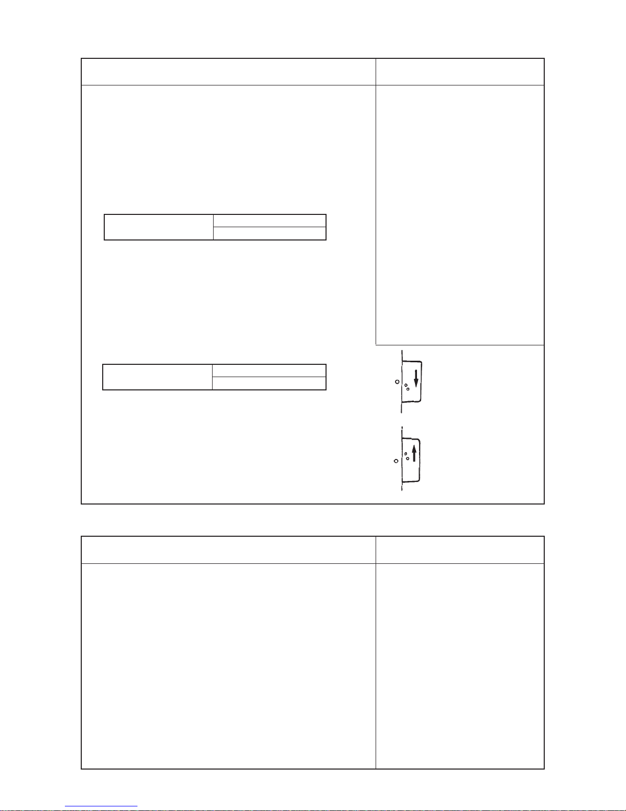
Adjustment Procedures Results of Improper Adjustment
Adjustment Procedures Results of Improper Adjustment
1) Set the feed amount to 2.5mm. (2 mm at the time of delivery)
Note, however, that the feed amount has to be set to “0” mm only for
LZ-2290SU and LZ-2290DU.
2) Adjusting the height of the feed dog
Loosen screw 1 and adjust the height of the feed dog by turning feed
driving link shaft 2.
3) Adjusting the inclination of the feed dog
Loosen screw 3. Put a screwdriver through the hole for the screwdriver
and adjust the inclination of the feed dog by turning the feed rocker
shaft with the screwdriver.
(Caution) 1. If the feed rocker shaft is not pressed in the direction A
(a) during the adjustment procedure, there will be a
play at the feed bar or washer will come off. So, be sure
to adjust the feed dog with the feed rocker shaft pressed
in the direction A (a).
2. Check to be sure that the feed dog is leveled with the
feed amount currently used when the top surface of
the ascending feed dog is flush with the top surface of
the throat plate.
™ Perform the adjustment of the
inclination of the feed dog according
to the sewing process.
(Example)
™ When the feed force is required in
such a process of tape attaching or
the like :
Adjust so that this side of the feed
dog is raised.
™ When using the slippery material in
such a process of attaching a facing
of girdle :
Adjust so that the feed dog should
be leveled.
A. Adjusting procedure by removing the gear box cover
1) Remove the gear box cover. (Refer to the item “4-(1).)
2) Adjust the marker line engraved on the thread take-up to the timing mark G
engraved on the face plate.
3) Set the feed amount to 2.5 mm. However, the feed amount has to be set to
“0” mm only for LZ-2290SU and LZ-2290DU.
4) In the aforementioned state, loosen the setscrew in the hook driving shaft
sprocket and adjust the timing mark engraved on the feed rocker cam to
the timing mark engraved on the feed rocker rod.
(Caution) In this case, the hook timing (thread trimming timing for the
machine equipped with a thread trimmer) changes. Be sure to perform
re-adjustment.)
B. Adjusting procedure with the gear box cover attached (For fine
adjustment)
1) Set the feed amount to 2.5 mm.
* Refer the adjusting procedure for LZ-2290SU and LZ-2290DU to page 11.
2) Adjust the marker line engraved on the thread take-up to the marker line
engraved on the face plate.
3) In the aforementioned state, loosen the setscrew in the hook driving shaft
sprocket. Now, turn the hook driving shaft to adjust so that the feed dog
comes down. Adjust so that the top surface of the feed dog is aligned with
the top surface of the throat plate when the feed dog comes down.
* There is a slight inclination at the feed dog. Adjust the feed dog so that “0”
to 6 teeth come out from the top surface of the throat plate.
(Caution) After the aforementioned adjustment, “hook timing” and
further “thread trimming cam timing” for the machine equipped with a
thread trimmer will change. Be sure to re-adjust them properly.
−8 −
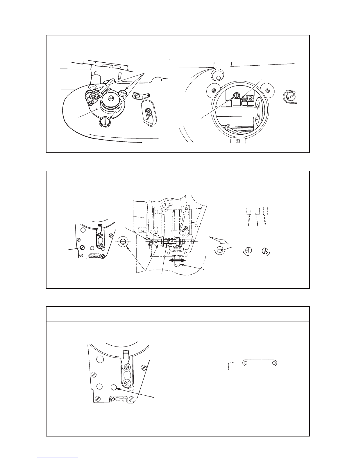
(3) Adjusting the feed amount
Standard Adjustment
(4) Position of the feed dog
Standard Adjustment
LZ-2290SS, DS
Condition : Feed amount : maximum
Feed bar
A
B
Feed crank stud
Timing mark
Normal feed amount
regulation metal fitting
Feed spring hook
Feed converting
arm A (asm.)
Feed adjusting link
Reverse feed amount
regulation metal fitting
LZ-2290SU, DU
1
2
3
1
2
1
−9 −
Adjustment Procedures Results of Improper Adjustment
Adjustment Procedures Results of Improper Adjustment
[Feed “0” adjustment]
1) Set the stitch length dial at “0”.
2) Loosen screw 1, and align the timing mark on the feed crank stud
with that on the feed crank stud support.
(The position of the timing mark differs with models.)
3) When loosening screw 1, confirm that there is no axial play at the
feed converting arm A (asm.) and tighten screw 1.
[Normal feed adjustment]
4) Set the stitch length dial at the maximum value of the gauge to be
used.
* Normal feed is regulated to 2 mm at the time of delivery.
5) Loosen screw 2, make the feed adjusting link come in contact with
the screw and tighten screw 2.
[Reverse feed adjustment]
6) Loosen screw 3, pushing the feed lever down to make the sewing
machine enter the reverse feed stitching mode, press reverse feed
amount regulation metal fitting against the projecting section of the
reverse feed adjusting link B. Now, tighten screw 3. (Set the
condensation stitch length adjusting dial to the maximum value on
the scale.)
* Reverse feed is regulated to 2 mm at the time of delivery.
7) To decrease the reverse feed stitching length for fastening stitching,
use the condensation stitching function. (Refer to “Adjusting the
condensation stitching mechanism” in the Instruction Manual for the
LZ-2290 Series.)
™ The engraved dot is for reference only and fine adjustment is
necessary. When the ratio of sewing length (as many as 10 stitches)
of normal and reverse feed is approximately 90% in case of straight
stitch feed amount of 2 mm, the adjustment is OK.
In case of thread trimming
™ If the timing marks are not aligned
with each other, the actual feed
amount will be different from the
feed amount specified on the stitch
length dial. If the timing marks
greatly separate from each other,
the normal or reverse feed amount
will be increased causing the feed
dog to come in contact with the
thread trimming counter knife.
™ The feed dog will come in contact
with the throat plate.
1) Set the stitch length dial at the maximum.
2) Turn the handwheel, and fix the feed dog so that the clearances in
front and rear are the same at the position where the feed dog does
not come in contact with the throat plate.
™ In the case where the gear box (large) cover is not opened, loosen
screw 1 to adjust the position.
™ In the case where the gear box (large) cover is opened, loosen screw
2 to adjust the position.
Max. normal feed amount
of the mechanism
LZ-2290SS, DS=5 mm
LZ-2290SU, DU=2.5 mm
Max. reverse feed amount
of the mechanism
LZ-2290SS, DS=4 mm
LZ-2290SU, DU=2.5 mm
Normal feed → large
Reverse feed → small
Nomal feed → small
Reverse feed → large
−10 −
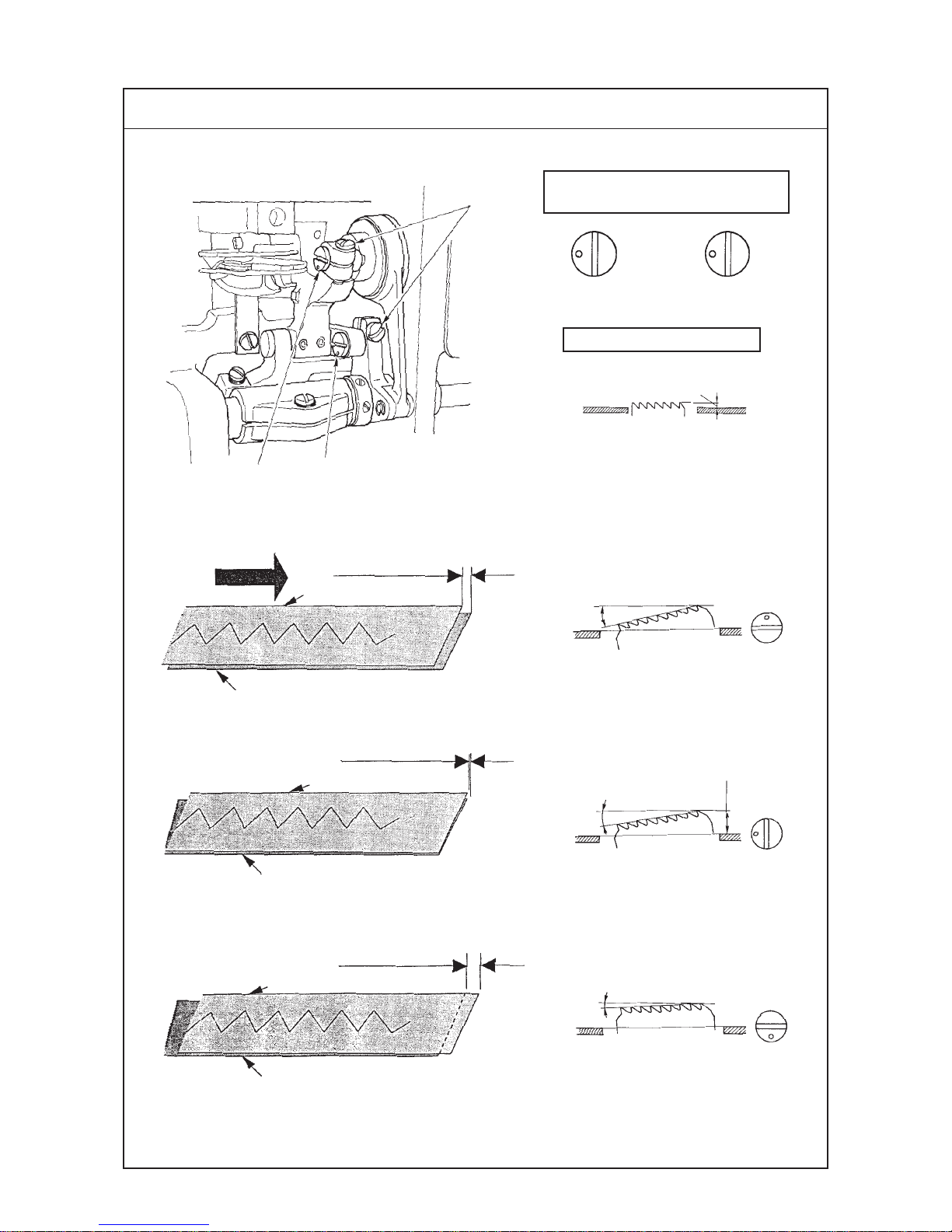
(5) Adjusting the slippage of materials (For LZ-2290SU and LZ-2290DU)
Standard Adjustment
1.4mm
θ
1.4 mm
θ
θ
Standard state of engraved marker
dot of vertical feed link shaft
Standard height of feed dog
Operator’s
side
Sewing direction
Upper material
Lower material
Minus slippage
of material
Upper material
Lower material
Upper material
Lower material
“0” slippage
of material
Plus slippage
of material
Standard position
1
2
3
23
3
3
3
−11 −
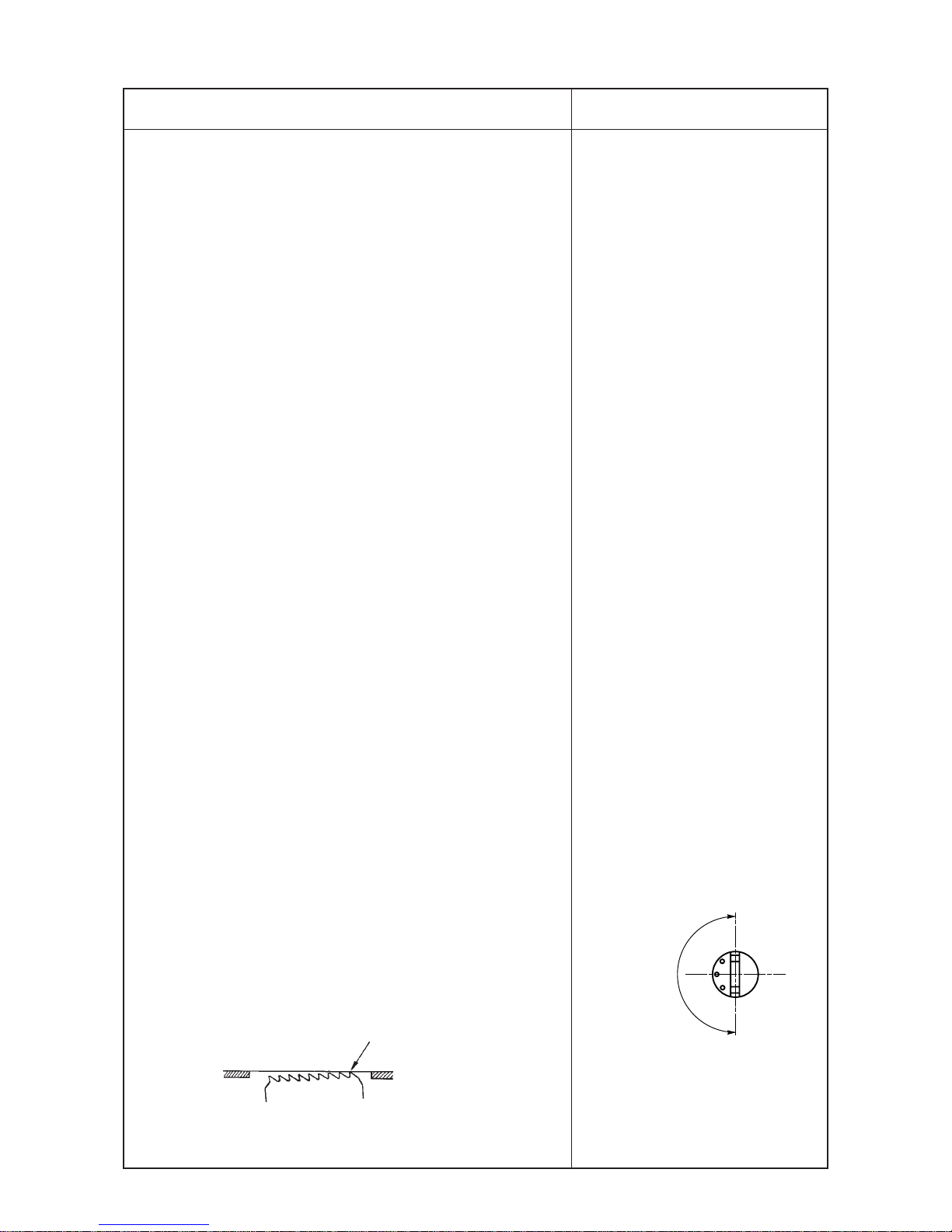
Adjustment Procedures Results of Improper Adjustment
1) To adjust the height and inclination of the feed dog, loosen setscrews
1 in the vertical feed link shaft and turn vertical feed link shafts 2
and 3 with a screwdriver.
2) The standard inclination is the position where the engraved marker
dots of vertical feed link shafts 2 and 3 face in the direction of 9
o’clock (left side).
3) The standard height of the feed dog is 1.4 mm from the top surface of
the throat plate.
<Adjusting the slippage of materials>
◎ This machine can adjust “Amount of slippage of materials” by
adjusting the height and inclination of the feed dog.
4) Mainly adjust vertical feed link shaft 3.
The amount of slippage of materials can be adjusted by the position
of the engraved marker dot which means the size of each theta θ of
the inclination of the feed dog.
* Points of adjustment
™ Quality of finished products is improved when the slippage of materials
is slightly adjusted to the minus state. (Operator’s hand pressure
should be considered in actual sewing.)
™ When performing the adjustment, simultaneously adjusting vertival
feed link shafts 2 and 3 makes it difficult to see the characteristic of
the slippage of the material. So, set 2 to the standard state (reference)
and mainly adjust 3.
™ In the case where the slippage of material (0 to minus) cannot be
obtained by adjusting vertical feed link shaft 3 only, adjust vertical
feed link shaft 2 so that theta θ , inclination of the feed dog is
increased.
* 1 Set the feed pitch to “0” mm.
2 Adjust with the hook driving shaft sprocket so that the feed dog
on this side is aligned with the top surface of the throat plate when
the marker line engraved on the thread take-up is aligned with
mark A on the face plate.
™ The height 1.4 mm of the feed dog
has been factory-set at the time of
delivery. Change the height in
accordance process the process.
(Characteristic of slippage of
materials changes. So, be careful.
™ Characteristic of slippage of
materials changes in accordance
with materials.
(The relation between the direction
of the engraved dot and slippage of
materials described in the
Engineer’s Manusl is the standard
of adjustment.)
™ Adjust on the left-hand side the
adjusting positions of the engraved
marker dots of vertical feed link
shafts 2 and 3.
If the position of the engraved
marker dot is on the right-hand side,
the effect of prevention of slippage
of material is difficult to be obtained.
™ When the adjustment of the height
of the feed dog has been performed,
the sewing pitch is different from the
scale on the stitch length dial. Readjust the scale with the actual
sewing pitch.
Range of use
of engraved
marker dot
Left Right
To align
Operator’s side
−12 −
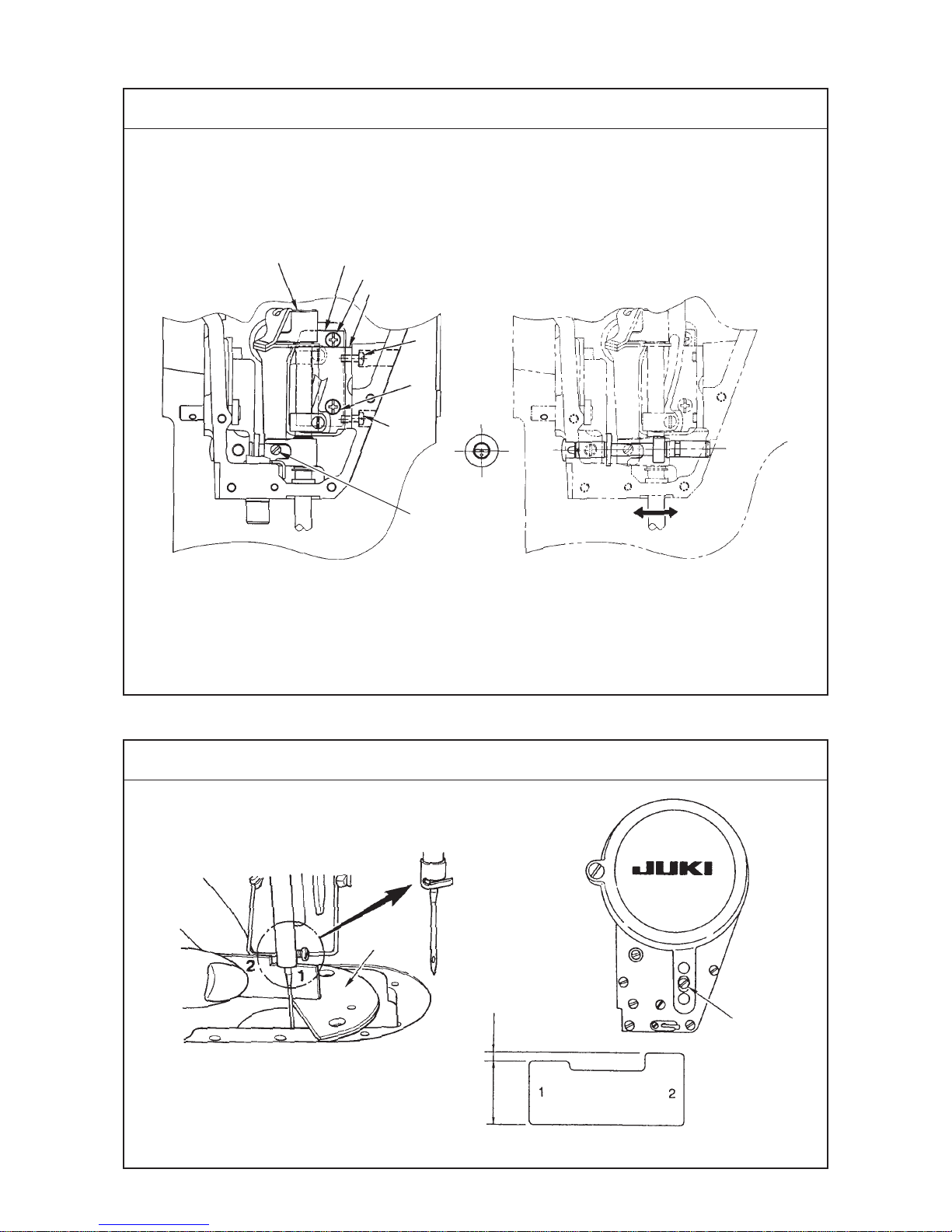
(6) Adjusting the origin of the needle rocking motor
Standard Adjustment
™ Adjustment of the origin is performed when the needle rocking amount in terms of the center is not
equal, or the motor or the sensor is required to be replaced.
Assemble link 9 and motor shaft
so as to be flush with each other.
<Condition of the origin “0”>
When the link is at 90˚, move the light-up sensor
from the rightend to the left. The position of the
origin “0” is when the sensor gose out.
1) 2), 5)
3)
4)
6)
Needle rocking
motor cover
Needle rocking
unit base
Motor
Origin sensor
(asm.)
Sensor
installing base
90˚
Positioning jig
90˚
1
2
3
4
6
5
7
8
9
1
6

−13 −
Adjustment Procedures Results of Improper Adjustment
1) Remove four setscrews 1 in the needle rocking motor cover.
2) Remove three setscrews 2 and counter sunk screw 3.
(At this time, loosen setscrew 4 in the needle bar support
base shaft connecting stud as well. Refer to the item “(7)
Adjusting the needle entry position”.)
* When assembling, after temporarily tightening screws 3 and
2, tighten in the order of 3 and 2.
3) Move the needle bar in the direction of the face plate, draw out
the needle bar support base shaft from the needle bar support
base shaft connecting stud, and remove the shaft together with
the needle rocking unit base from the machine arm.
In case of replacing or adjusting the needle rocking motor
* For the replacement of the sensor, refer to the item of the
sensor.
4) Loosen setscrew 5 in the motor link bracket and remove link
9.
5) Loosen four setscrews 6 in the needle rocking unit base and
remove the motor to replace.
6) Tighten setscrew 5 in the motor link bracket.
(Check also setscrew 7 in the motor link.)
In case of replacing or adjusting the sensor
7) Confirm that the sensor lamp lights up in the hook adjusting
mode.(See p.18.)
8) Loosen setscrews 8 in the sensor installing plate, move the
sensor installing plate to the right-hand end once, and gradually
move it to the left-hand side. Tighten setscrews 8 when the
sensor lamp goes out. This state is “0” of the origin. (However,
it is when the link is at 90˚.)
™ To determine the position of the sensor, it is convenient to
make a positioning jig as shown in the figure on the left.
−14 −
(7) Adjusting the needle entry position (In terms of needle rocking direction)
Standard Adjustment
(8) Adjusting the longitudinal play at the needle bar
Standard Adjustment
(9) Adjusting the needle entry position (In terms of longitudinal direction)
Standard Adjustment
Needle bar support base shaft
connecting stud
As observed from
the face plate side
Engraved
marker dot
For an
excessive play
Adjusting needle
entry position
Needle enters the
center of needle slot.
For an
excessive play
It is not necessary to remove the face plate.
Needle bar support
base guide shaft
Needle bar
1
2
3
1
2
3
−15 −
Adjustment Procedures Results of Improper Adjustment
Adjustment Procedures Results of Improper Adjustment
Adjustment Procedures Results of Improper Adjustment
B
A
A = B
1) Loosen setscrews 2 and remove bobbin winder unit 1.
2) Set both zigzag width and stitch base line to the position of “0”.
Set the position of the needle to the center and teporarily tighten it.
3) Set the zigzag width to 8 mm which is factory-adjusted at the time of
delivery, and securely tighten screw 3 at the position where the
clearances of zigzag widths A and B are equal.
Conditions : Needle enters the center of zigzag width.
: Max. zigzag width (8 mm)
(Caution) Do not flap or strongly press the needle bar at the time of
adjustment.
1) Loosen the screw, which can be observed through the hole for
adjustment, in the needle bar support base guide shaft with the face
plate attached.
2) Move the needle bar back or forth to adjust so that the needle enters
the center of the needle slot in the throat plate.
3) Fix the needle bar support base guide shaft.
4) Be sure to check the needle throw torque applied to the needle bar
support base.
(Caution)
1. The needle entry position in terms of the longitudinal direction
should be finely adjusted. If the needle bar has to be moved by
a large margin for the adjustment of the needle entry position in
case of replacement of gauges, carry out the adjustment
referring to “(10) Position of the needle bar connection guide”.
2. Be sure to check the left/right plays at the needle bar support
base.
In the case where there is any extra load applied to the base,
needle throwing action will be affected.
1) Loosen screw 1 in the face plate.
2) Remove rubber cap 2. Then tighten screw 1 while pressing pin 3 in
the needle bar support base guide located inside the face plate with a
screwdriver.
3) At this time, move the needle bar to the right and left by hand to confirm
that there is neither extra load nor a longitudinal play.
4) If the load applied to the needle bar and the longitudinal play existing at
the needle bar at the rightmost needle throw position differ from those
at the leftmost needle throw position, perform the adjustment by turning
pin 3 in the needle bar support base guide to change the orientation of
the engraved marker dot (toward the direction where the load and play
are larger).
(Caution) Be sure to check the longitudinal play at the needle bar
support base. In the case where there is any longitudinal play or
extra load, the needle throwing action will be affected.
™ Thread will not be uniformly tensed
when the needle throws to the right
and left, or thread breakage or
needle breakage will result.
−16 −
(10) Position of the needle bar connection guide
Standard Adjustment
(11) Height of the needle bar
Standard Adjustment
Conditions : Zigzag width : “0”
Position of needle position changing lever : Center
™ Part No. of engraved indication E
: 22536502
Dimension a: 12.2 mm
Dimension b: 3.4 mm
Woodruff
plate
Engraved
indication
Timing gauge
Needle bar
support base
Needle bar
connection guide
Needle bar crank
rod guide
1
2
3
4
5
1
a
b

−17 −
Adjustment Procedures Results of Improper Adjustment
Adjustment Procedures Results of Improper Adjustment
1) Loosen the screw in the needle bar support base shaft referring to “(7)
Adjusting the position of needle entry (in terms of the needle rocking
direction)”.
2) Remove the thread take-up cover, thread take-up and face plate. Then
loosen screws 2 and 3 in the needle bar connection guide together
with screws 4 and 5 in the needle bar crank rod guide.
3) Loosen screw 1 in the needle bar support base guide shaft and adjust
the needle entry point in terms of longitudinal direction. Then tighten
the screw. (Refer to “(9) Adjusting the needle entry position (in terms of
longitudinal direction”.)
4) Bring the needle bar to the lower dead position. Move the needle bar
support base in the needle rocking direction until a position at which the
base smoothly slide without a play is found. Now, temporarily tighten
screw 3 in the needle bar connection guide.
5) Bring the needle bar to the upper dead position. Move the needle bar
support base in the needle rocking direction until a position at which the
base smoothly slide without a play is found. Now, temporarily tighten
screw 2 in the needle bar connection guide.
6) Sliding the needle bar support base, tighten screws 2 and 3 in the
needle bar connection guide.
7) Tighten screws 4 and 5 in the needle bar crank rod guide the same as
the steps 4), 5) and 6).
* Set the needle throw torque at the needle bar support base to 500g or
less.
8) Tighten the screw in the needle bar support base shaft referring to “(7)
Adjusting the position of needle entry (in terms of the needle rocking
direction”.
9) Attach the thread take-up cover, thread take-up and face plate in position.
(Caution) Be sure to check the longitudinal play at the needle bar
support base. In the case where there is any longitudinal play or
extra load, the needle throing action will be affected.
1) Set the mode to the hook adjusting mode. (See p.18.)
2) Remove the presser foot, throat plate, woodruff plate and feed
dog.
3) Place the woodruff plate on the surface of the machine bed onto
which the throat plate is to be attached. Now, loosen screw 1
and adjust so that the distance from the top face of the woodruff
plate to the bottom end of the needle bar is equal to the height
ofthe “1” side of the timing gauge.
(Caution) Thickness of the throat plate may be different from
that of the woodruff plate. So, be sure to use the woodruff
plate for the adjustment. (Thickness of the woodruff plate :
2 mm)
™ Engraved indication “1” side is the height of the needle bar and
“2” side the needle-to-hook timing.
(Caution) Even when the timing gauge is used, the indented
part of the needle may come in contact with the blade point
of the hook in accordance with the kind or size of the needle.
In this case, slightly lower the needle bar to adjust the height
to the indented part of the needle.
For the LZ-2290 Series, use timing gauge E.
−18 −
(12) Adjusting the needle-to-hook timing and the needle guard
Standard Adjustment
™ Hook adjusting mode
™ Lifting amount of the nedle (bar) : 3.4 mm
™ When the zigzag width is maximized, a distance of
0.2 to 0.5 mm should be provided between the top
end of the needle eyelet and the blade point of the
hook when the needle reaches the leftmost end of
the zigzag stroke.
™ The needle guard :
• has to guard the needle both on the right- and lefthand sides.
• A clearance of 0 to 0.05 mm should be provided
between the needle and the blade point of the hook
(when the needle reaches the rightmost end of the
zigzag stroke).
Remarks Marker lines engraved on the face plate
™ The needle-to-hook timing is adjusted using the
timing gauge as described above. However, you
can use the marker lines engraved on the face plate
for reference when adjusting it.
™ Be sure to remember that the marker lines are used
only for reference. So, it is recommended to use
the timing gauge for adjusting the needle-to-hook
relation so as to make the most out of many
functions of the LZ-2290 Series models of sewing
machine.
0.2 to 0.5 mm
Woodruff plate
Or,
Fig. 1
Fit the blade point of the
hook onto the indented
part of the needle.
(Approximately 0.05 mm)
Fig. 2
0 to 0.05 mm
Blade point
of the hook
Needle
Needle guard
Fig. 3
1
2
3

−19 −
Adjustment Procedures Results of Improper Adjustment
Name of pattern Stitch pattern Max. zigzag width
Standard zigzag 8 mm
2-step zigzag 10 mm
3-step zigzag 10 mm
Scallop 8 mm
Blind stitch 8 mm
Custom pattern – 8 mm
1) Pressing setting switch 1, turn ON the power when performing
hook adjustment.
2) At this time, bobbin thread counter 2 displays lateral three
bars.
3) The sewing machine does not run even when depressing the
front part of pedal during the hook adjusting mode.
4) Zigzag operation works by turning the handwheel by hand.
5) For hook adjustment, make use of 2-step zigzag pattern 3 to
adjust left/right/center.
6) To return from hook adjusting mode to normal sewing mode,
turn off/on the power.
7) Set the needle bar to the position of zizag width “0”, and adjust
so that the blade point of the hook is brought to the center of
the needle at the height of the timing gauge on which “2” is
engraved. (Fig. 1)
8) At this time, adjust so that the blade point of the hook slightly
comes in cotact with the needle when the needle guard does
not come in contact with the needle (Fig. 2). Then tighten the
screw in the hook.
9) Maximize the zigzag width (see the table below). Adjust by
bending the needle guard so that the needle comes in contact
with the needle guard and does not come in contact with the
blade point of the hook at both the rightmost and leftmost needle
throwing positions. At this time, adjust so that a clearance of 0
to 0.05 mm is provided between the needle and the blade point
of the hook at the rightmost needle throwing position. (Fig. 3)
™ If the timing relation between the
needle and the blade point of the
hook is excessively advanced,
smaller thread loops will be
made particularly when the
needle throws to the right or
stitch skipping and thread
breakage will result.
™ If the timing relation between the
needle and the blade point of the
hook is excessively retarded,
larger thread loops will be made
particularly when the needle
throws to the left resulting in
tilted thread loops and stitch
skipping.
™ If the needle guard does not
come in contact with the needle,
the needle vibrates when the
sewing machine runs at high
speed resulting in thread
breakage and stitch skipping.
™ If the needle comes in contact
with the blade point of the hook,
the blade point will be damaged
resulting in an extraordinary
shortened service life of the
hook.
(Caution)
1. Hook is common to the LZ-2290 Series.
Part No. is 225258. Designate the hook with the part No.
when replacing it.
2. When changing the kind or size of the needle, be sure
to check the clearance between the needle and the blade
point of the hook.
3. The maximum zigzag width is regulated to 8 mm since
the standard gauge is 8 mm at the time of delivery.
−20 −
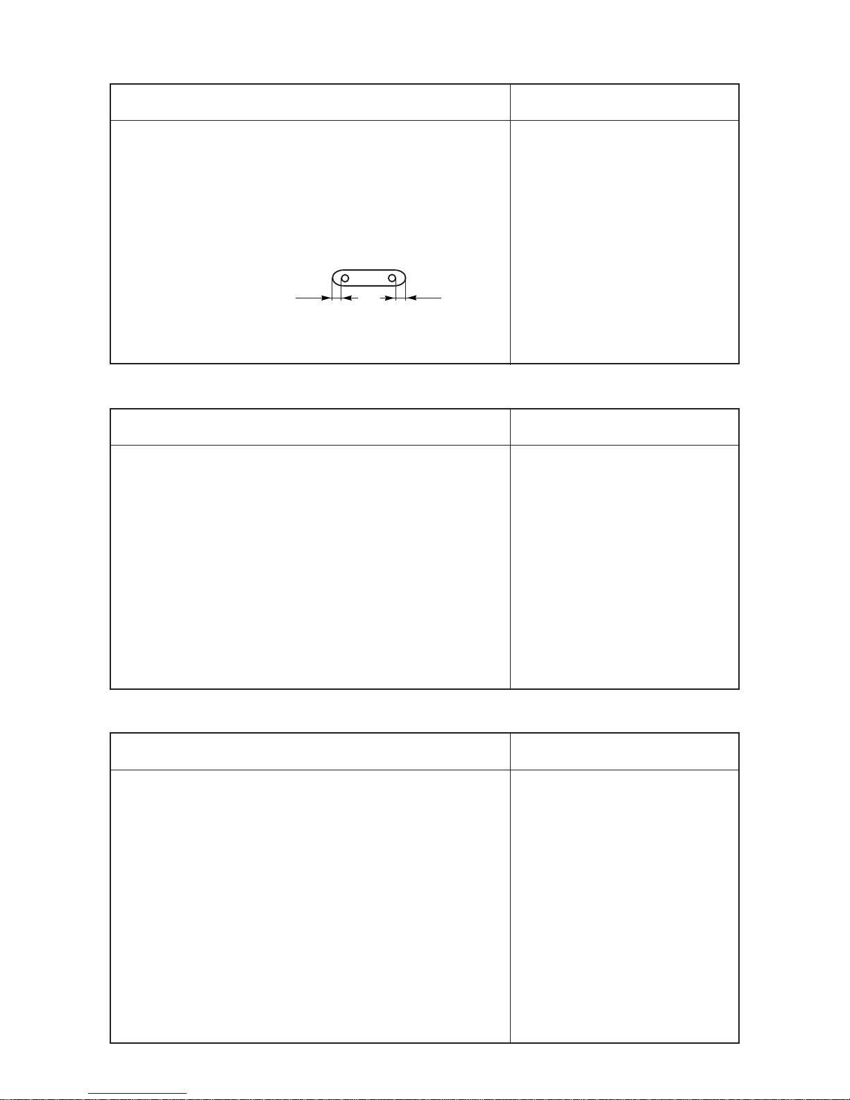
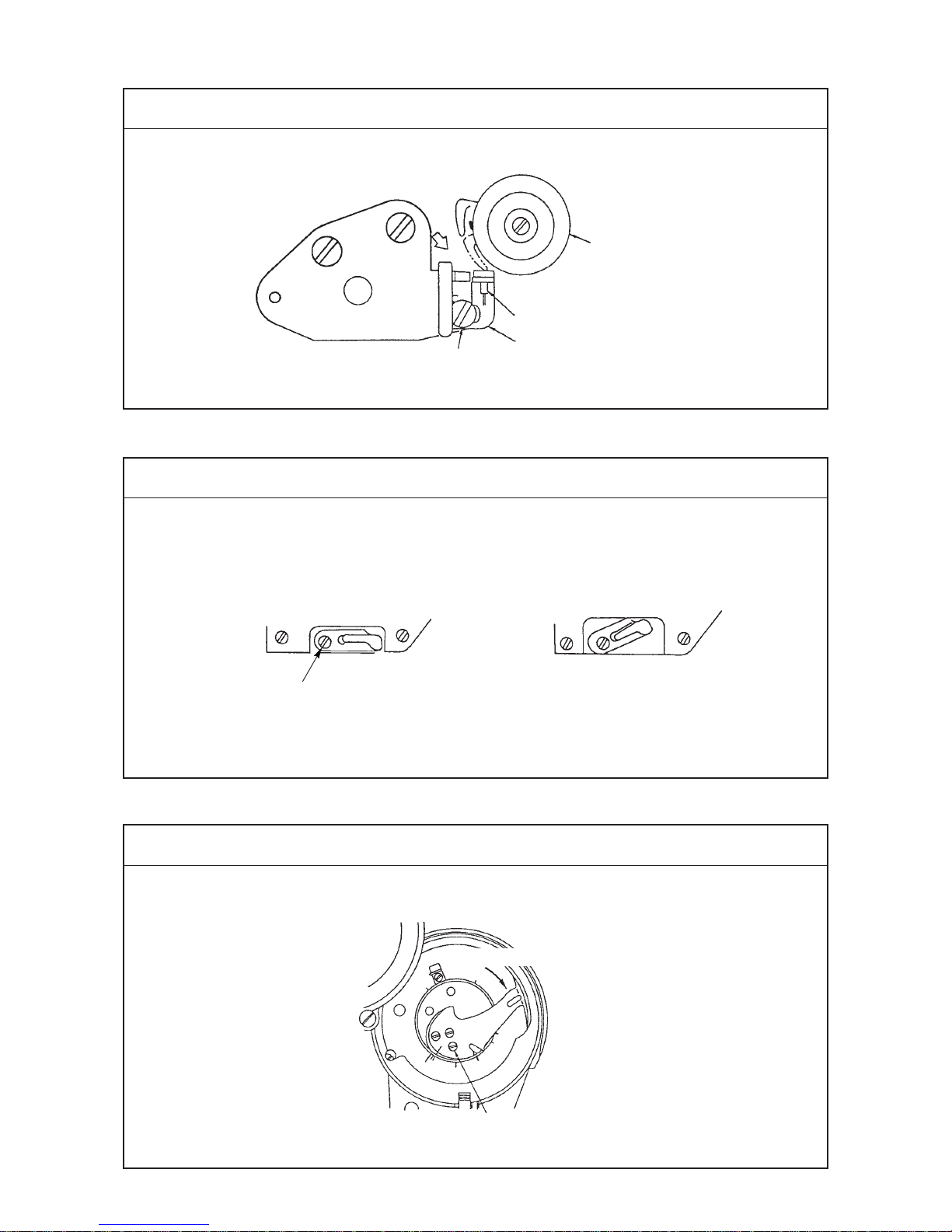
(13) Position of the bobbin case stopper
Standard Adjustment
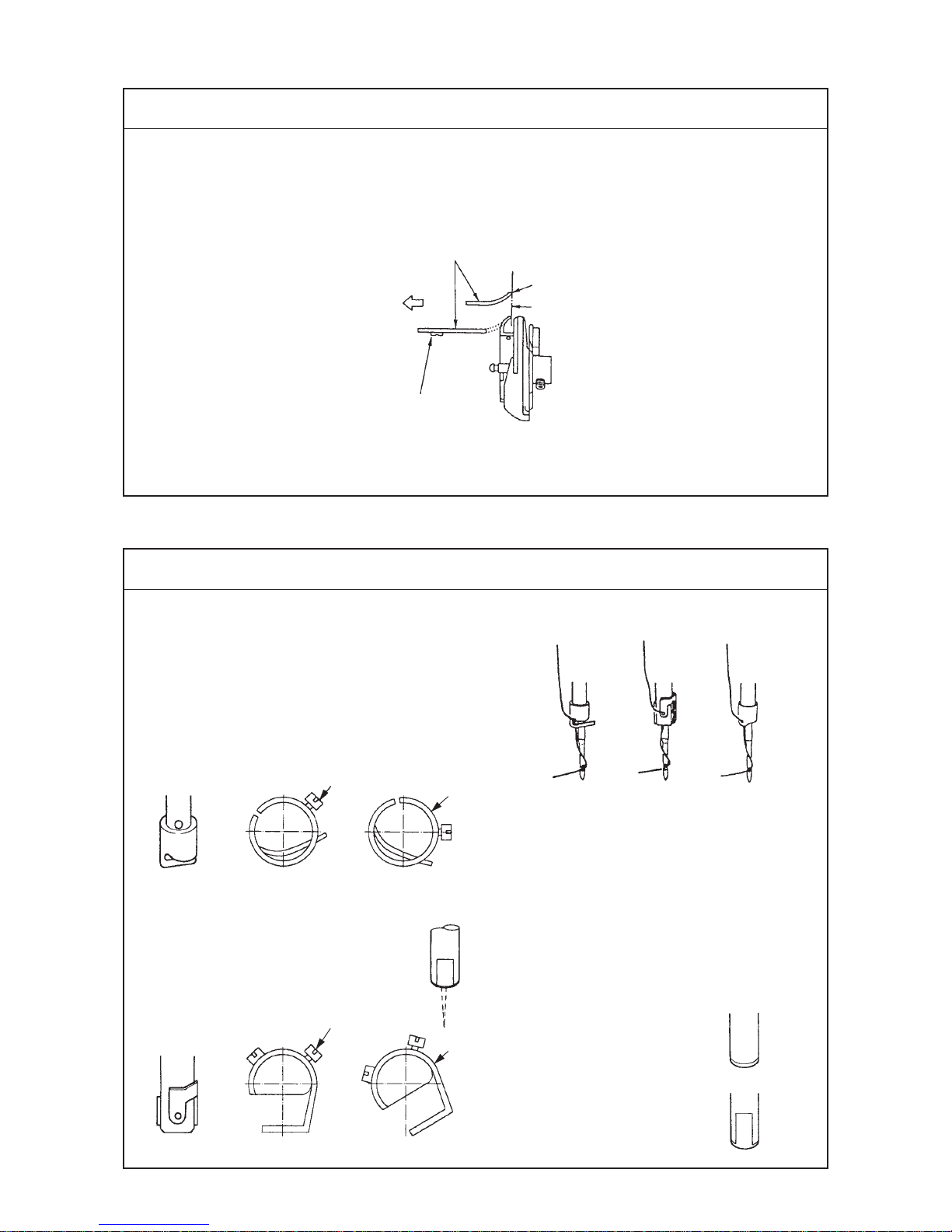
(14) Orientation of the needle bar thread holder
Standard Adjustment
™ The bobbin case stopper should be located within the range from the position at which top end A
of the bobbin case stopper is aligned with line B to the position that is 0.5 mm away from line B
in direction C.
Bobbin case stopper 2
Screw 1
™ The needle bar thread holder varies
in accordance with the needle bar.
1) In case of no flat portion at the bottom end of
needle bar
Install the holder so that the flat portion at
the bottom end of needle bar faces to this
side, or the right end faces to the rear end.
2) In case where the flat portion is at
the bottom end of needle bar
Install the holder so that the thread
hole faces to this side.
Front (Good) (No good)
Front (Good) (No good)
™ There are three different kinds of the needle
bar thread holders.
(1).... In ase of without auxiliary thread take-up
and without flat portion at the bottom of
needle bar
(2).... In case of with auxiliary thread take-up and
with flat portion at the bottom of needle bar
(3).... In case of without auxiliary thread take-up
and with flat portion at the bottom of needle
bar (Used for the machine equipped wuth
the wiper)
Without flat portion
(Part No. : 22507800)
With flat portion
(Part No. : 22507503)
Needle bar
(1) (2) (3)
A
B
C
1
2
3
3

−21 −
Adjustment Procedures Results of Improper Adjustment
Adjustment Procedures Results of Improper Adjustment
1) Loosen screw 1 and adjust the position of bobbin case stopper
2 by turning the entire unit of the bobbin case stopper.
(Caution) After the position of the bobbin case stopper has
been adjusted, turn the bobbin case by fingers in the
reverse direction of rotation to confirm that the bobbin case
will never slip out of the small claw.
™ Loosen needle clamp screw 2 or needle bar thread holder
screw 1, and adjust the position of needle bar thread holder
3 with respect to the needle bar.
™ Loosen the screw in the needle bar connection, and adjust the
entire unit of the needle bar and needle bar thread holder.
™ If the orientation of the needle
bar thread holder is not properly
adjusted, the thread is likely to
untwist resulting in thread
breakage.
−22 −
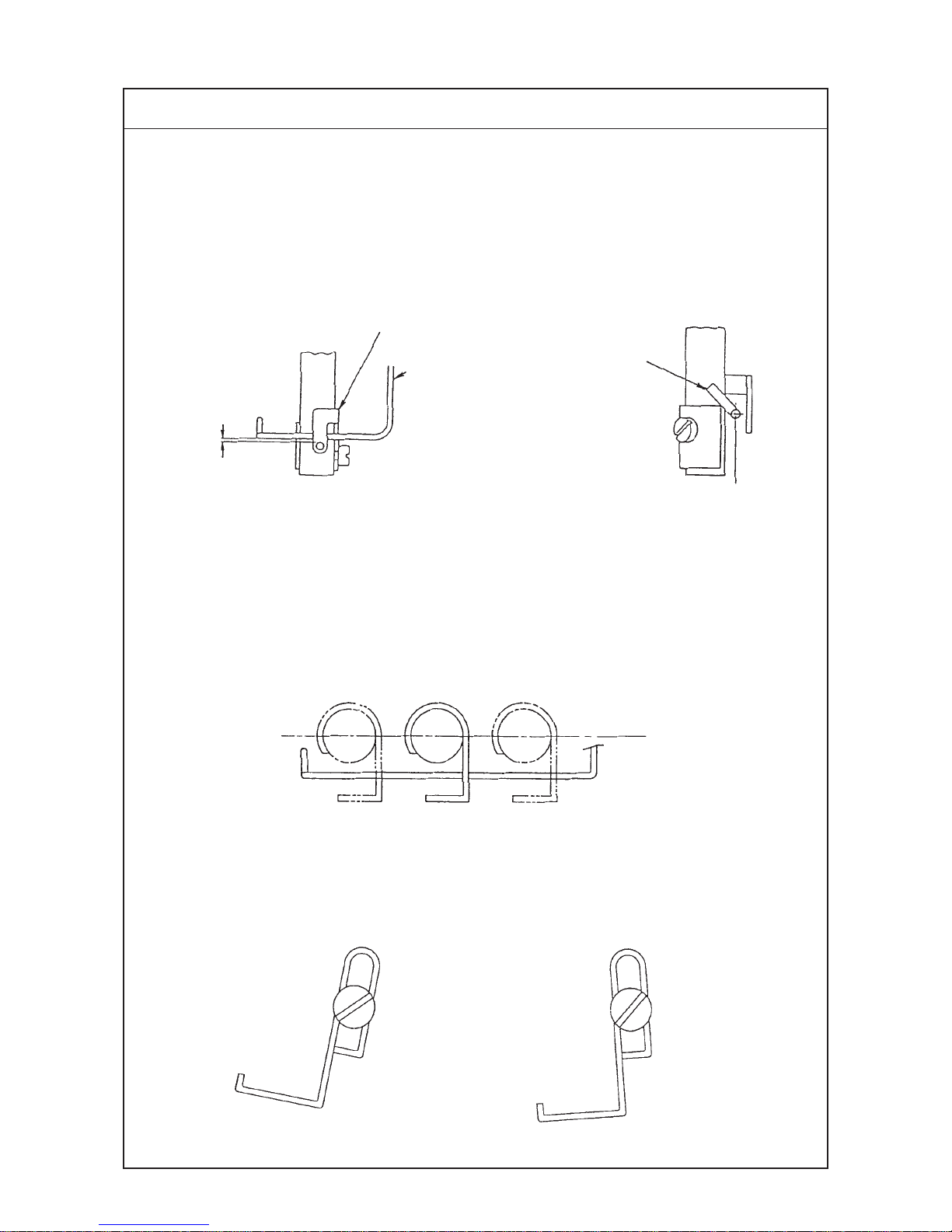
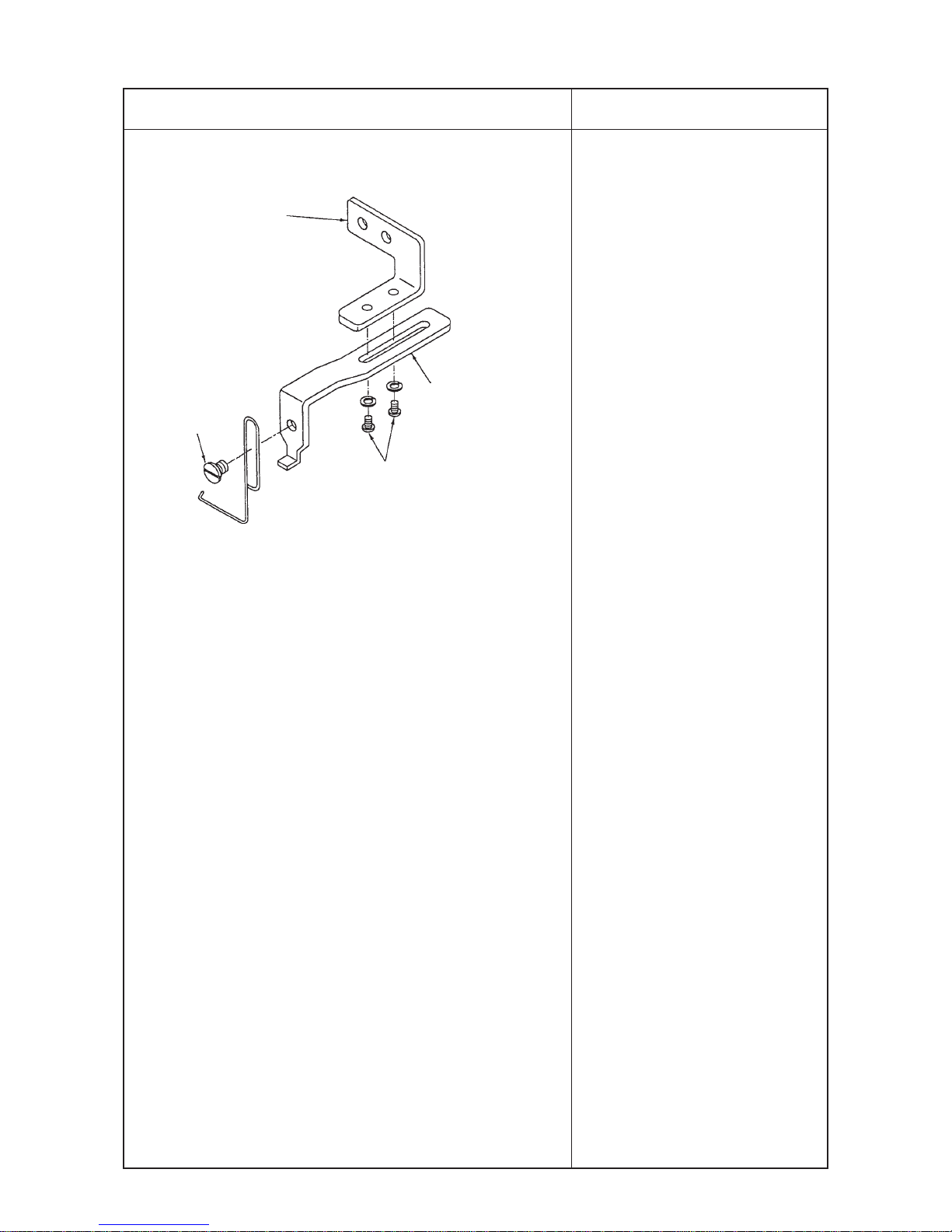
(15) Auxiliary thread take-up lever
Standard Adjustment
™ Vertical position
When the needle bar is in the lowest position of its stroke, the distance from the top end of the
eyelet in the needle bar thread holder to the bottom end of the auxiliary thread take-up lever
should be 0 to 1 mm.
™ Longitudinal position
The auxiliary thread take-up lever, as observed sideways, moves the center of the needle bar and
needle bar thread holder while keeping in parallel to the needle rocking stroke.
0 to 1 mm
Needle bar thread
holder
Auxiliary thread
take-up lever
Auxiliary thread
take-up lever
Center
Needle bar thread holder
In parallel to the needle rocking stroke
Auxiliary thread
take-up lever
Even when the auxiliary thread take-up
lever is positioned with its left-hand side
raised, no problem will result. ( ○)
The position of the auxiliary thread take-up
lever is not acceptable when it is positioned
with its left-hand side lowered. (X)
−23 −
Adjustment Procedures Results of Improper Adjustment
1) Loosen screw 1, and adjust the vertical position of the auxiliary
thread take-up lever. At this time, carefully position the auxiliary
thread take-up lever so that it is leveled or its left-hand side is
raised.
2) Loosen screws 2, and adjust the longitudinal position of the
auxiliary thread take-up lever. Use a thicker one of the hexagon
wrench keys supplied with the machine as accessories. At this
time, adjust so that the auxiliary thread take-up lever is in
parallel to the needle rocking stroke and tighten the screws.
™ If the auxiliary thread take-up
lever is lowered from the correct
vertical position, the thread takeup amount of the auxiliary
thread take-up lever will be
decreased and larger thread
loops will be produced.
™ On the contrary, if the auxiliary
thread take-up lever is raised,
the thread take-up amount of the
auxiliary thread take-up lever will
be increased and smaller thread
loops will be produced.
™ If the auxiliary thread take-up
lever is excessively raised from
the correct vertical position, the
auxiliary thread take-up lever will
come in contact with the needle
bar thread holder. So, be
careful.
™ If the longitudinal position of the
auxiliary thread take-up lever is
not proper or the auxiliary thread
take-up lever is not in parallel to
the needle rocking stroke,
thread breakage and stitch
skipping will be caused.
Auxiliary thread take-up
lever mounting bracket
Auxiliary thread
take-up lever base
1
2
−24 −
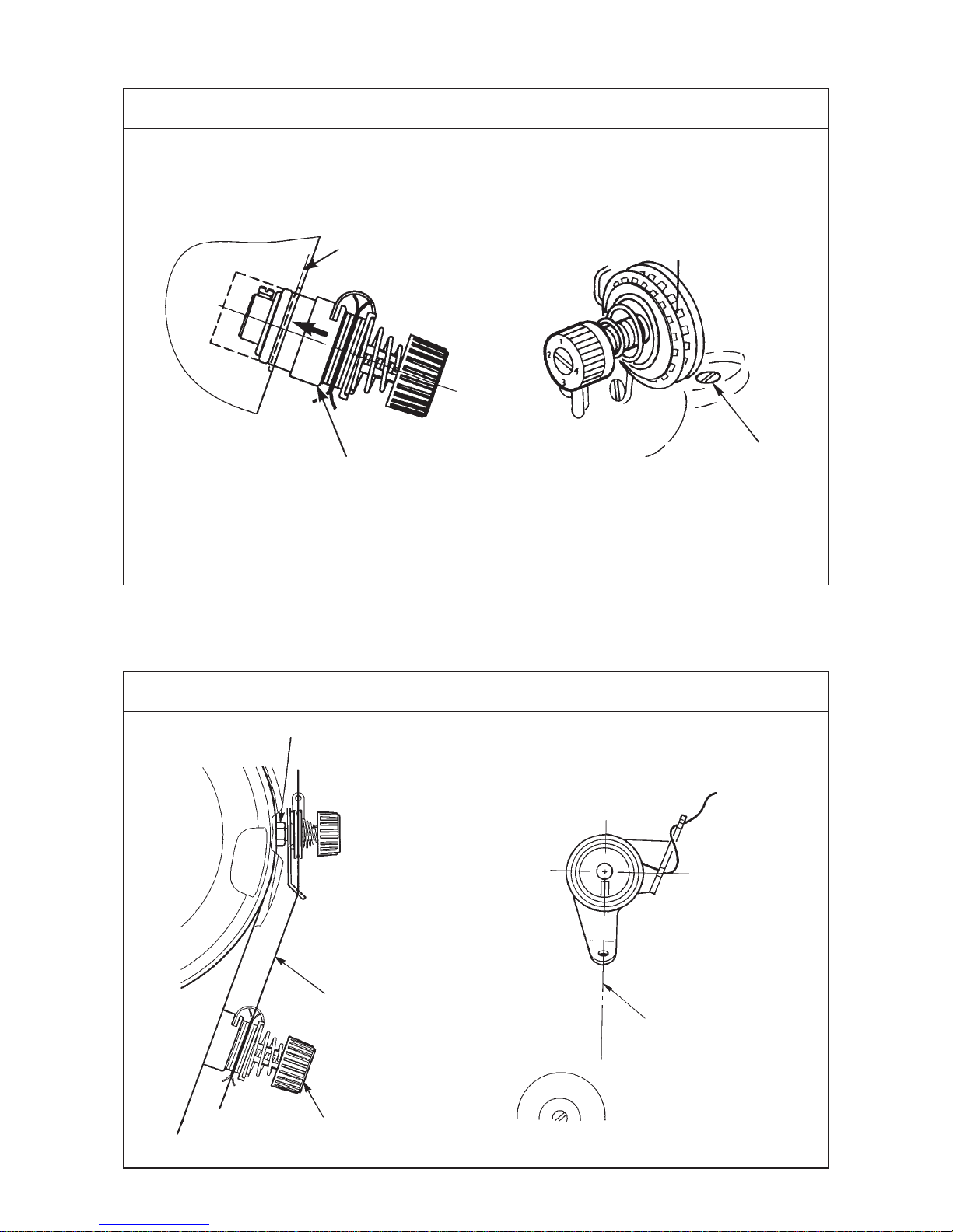
(16) Position of the thread tension
Standard Adjustment
(17) Position of the pre-tension
Standard Adjustment
Striking face on the
machine arm
Thread tension controller
Setscrew nut 1
Almost in parallel to
the machine arm
Thread should rnter the
rotary disk straight.
Fig. 2 Orientation
Fig. 1 Longitudinal position
Thread tension controller
1

−25 −
Adjustment Procedures Results of Improper Adjustment
Adjustment Procedures Results of Improper Adjustment
1) Loosen screw 1, and adjust the position of the thread tension
in the state that the thread tension controller is pushed to the
striking face on the machine arm.
1) Loosen setscrew nut 1, and adjust the longitudinal position of
the pre-tension so that the thread is in parallel to machine arm
as illustrated in Fig. 1.
2) Adjust the orientation of the pre-tension so that the thread
enters the rotary disk straight.
3) Adjust the pressure of the pre-tension so that the rotary disk
rotates smoothly.
™ If the orientation of the pre-
tension is improper, the thread
is bent, and unstable tension and
slip of the rotary disk will occur
resulting thread breakage or
stitch skipping.
1) Pressure of the pre-tension is
excessively low :
Rotary disk does not rotate
smoothly, and defective stitching
or thread breakage will occur.
2) In case of the sewing machine
with thread trimmer, if the
pressure of the pre-tension is
excessively high :
Thread slip at the needle top
after thread trimming or thread
slip at the needle top at the start
of sewing will occur.
−26 −
(18) Position of the thread take-up spring guard
Standard Adjustment
(19) Installing the thread take-up thread guide B
Standard Adjustment
(20) Installing the thread take-up
Standard Adjustment
D
F
C
G
A
B
E
Tension disk
Stopper rubber
Thread take-up spring guard
Direction of rotation
™ Fix the thread take-up with pressed in the direction of rotation.
1
1
NG
1
 Loading...