

Page 1

ENGLISH
CP-180
INSTRUCTION MANUAL
No.02
40088353
Page 2

CONTENTS
1. INSTALLING THE CONTROL PANEL ..........................................................................1
2. CONNECTING THE CORD ............................................................................................1
3. CONFIGURATION .........................................................................................................2
4. S
ETTING PROCEDURE OF THE MACHINE HEAD .....................................................2
5.
ADJUSTING THE MACHINE HEAD(direct-drive motor type sewing machine only)
6. EXPLANATION OF THE CONTROL PANREL ..............................................................4
7.
HOW TO OPERATE THE CONTROL PANEL FOR SEWING STITCHING PATTERNS
8. O
NE-TOUCH SETTING .................................................................................................9
9. P
RODUCTION SUPPORT FUNCTION .........................................................................9
10. HOW TO USE THE BOBBIN THREAD COUNTER ....................................................12
11. HOW TO USE THE THREAD TRIMMING COUNTER ................................................13
...3
...5
12. NEEDLE UP/DOWN COMPENSATION SWITCH .......................................................13
13. KEY LOCK FUNCTION ...............................................................................................14
14. ON/OFF SWITCH
15. AUTOMATIC THREAD TRIMMING SWITCH
16. ONE-SHOT AUTOMATIC STITCHING SWITCH
17. THREAD TRIMMING PROHIBITION SWITCH
18. FUNCTION SETTING SWITCH ...................................................................................15
19. O
PTIONAL INPUT/OUTPUT SETTINGS ....................................................................16
20. A
UTOMATIC COMPENSATION OF NEUTRAL POINT OF THE PEDAL SENSOR ...18
21. S
ETTING OF THE AUTO LIFTER FUNCTION ............................................................18
22. I
NITIALIZATION OF THE SETTING DATA ..................................................................19
23. C
HECKING PROCEDURE OF THE ERROR CODE ...................................................19
OF THE MATERIAL EDGE SENSOR ......................................14
.........................................................14
...................................................14
......................................................15
i
Page 3
WARNING :
This Instruction Manual is for the control panel, CP-180.
Read "Safety Instructions" of the Instruction Manual for the control box carefully beforehand and
understand them before using CP-180.
In addition, be careful not to splash water or oil on it, or shock such as dropping and the like since
this product is a precision instrument.
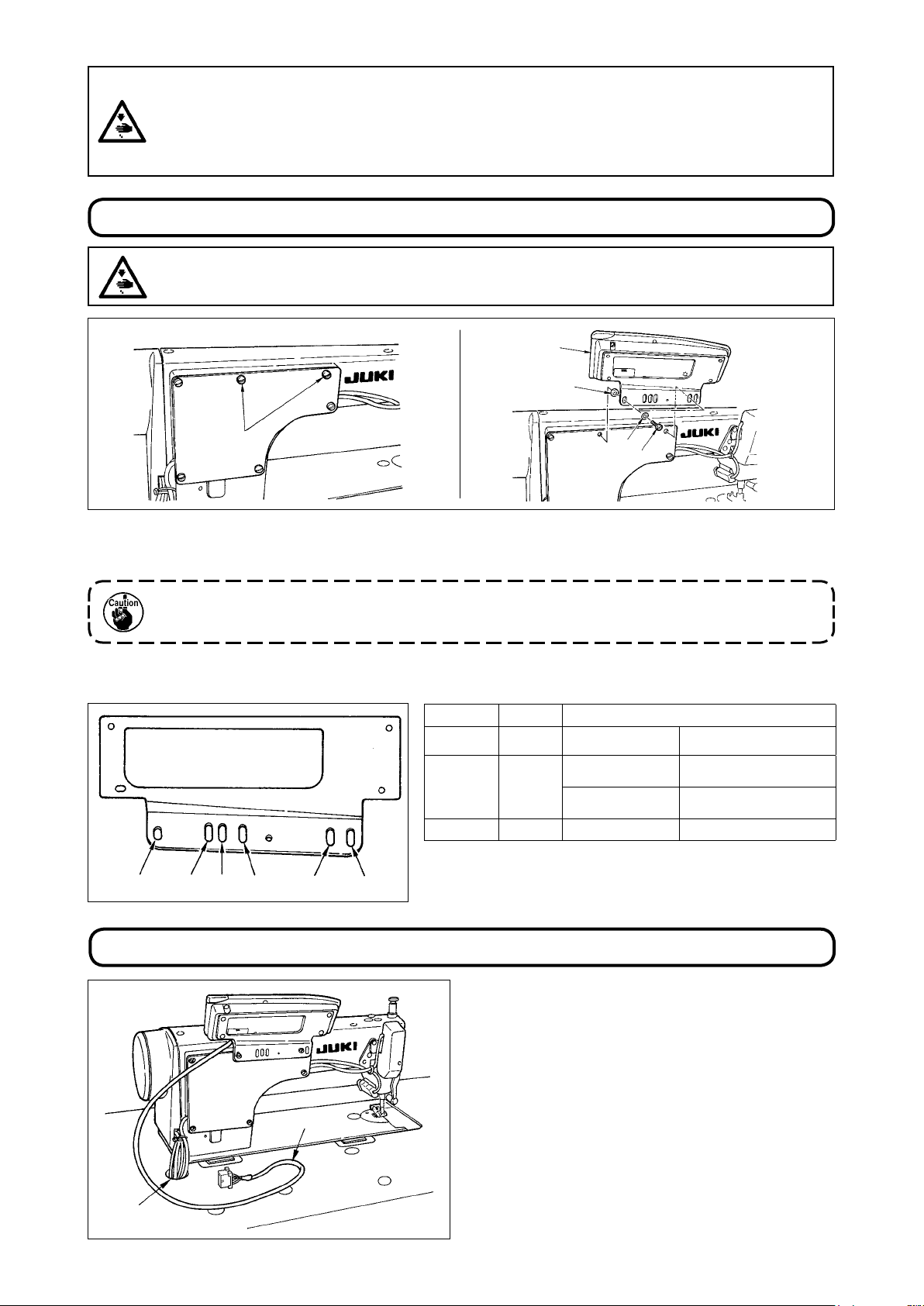
1. INSTALLING THE CONTROL PANEL
WARNING :
To prevent personal injury caused by abrupt start of the sewing machine, carry out the work after
turning OFF the power switch and ascertaining that the motor has completely stopped.
2
4
1
3
5
1) Remove side plate setscrews 1 from the s
ide plate.
2) Install control panel 2 on the machine head using screws 5, at washers 3 and rubber seat 4 suppl
ied with the control panel as the accessories.
1. DDL-9000B (Not provided with AK) is given as an example of installing procedure.
2. Screw to install the panel changes according to the machine head used. Refer to Table 1 and
conrm the kind of screw.
< The relation between the respective machine heads and the positions of installing hole of the bracket are as described in the table. >
Table 1
1 2
3 4 5
6
DDL-9000A
DDL-9000B
LH-3500A
Installing hole
-
1
5
-
1
5
-
2
5
12
M5 X
(Prov
ided with AK)
M5 X 14
(Not provided with AK)
M5 X 12
14 Side plate setscrew
M5 X
Screw
Screw supplied with panel
as accessories
Side plate setscrew
Screw supplied with panel
as accessories
2. CONNECTING THE CORD
1
A
1) Pass cord 1 of the control panel through hole A
in the machine table route it to the underside of
the table.
2) As for the connection of the connector, refer to
the Instruction Manual for the control box.
- 1 -
Page 4
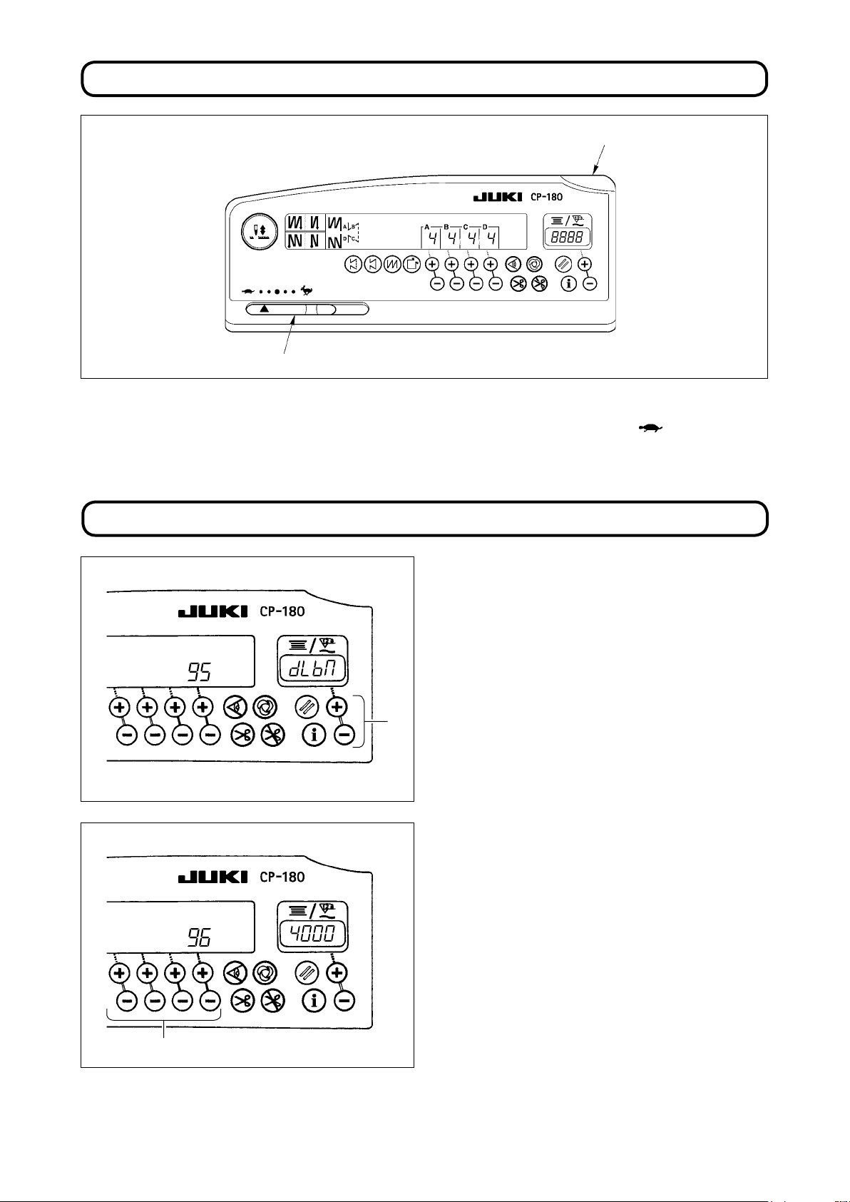
3. CONFIGURATION
1
2
Power indicator lamp (LED) : Lights up when the power switch is turned ON.
1
Max. speed limitation variable resistor : Limits the speed when it is moved to the left ( ).
2
4. SETTING PROCEDURE OF THE MACHINE HEAD
1) Refer to "18. FUNCTION SETTING SWITCH
p.15, and call the function setting No. 95.
2) The type of machine head can be selected by
pressing switch 1.
* Refer to "CAUTIONS WHEN SETTING UP THE
SEWING MACHINE" or "Machine head list"
on the separate sheet for the types of machine
1
heads.
3) After selecting the type of machine head, by
pressing switch 2, the step proceeds to 96 or
94, and the display automatically initializes to the
contents of the setting corresponding with the
type of machine head.
"
2
- 2 -
Page 5
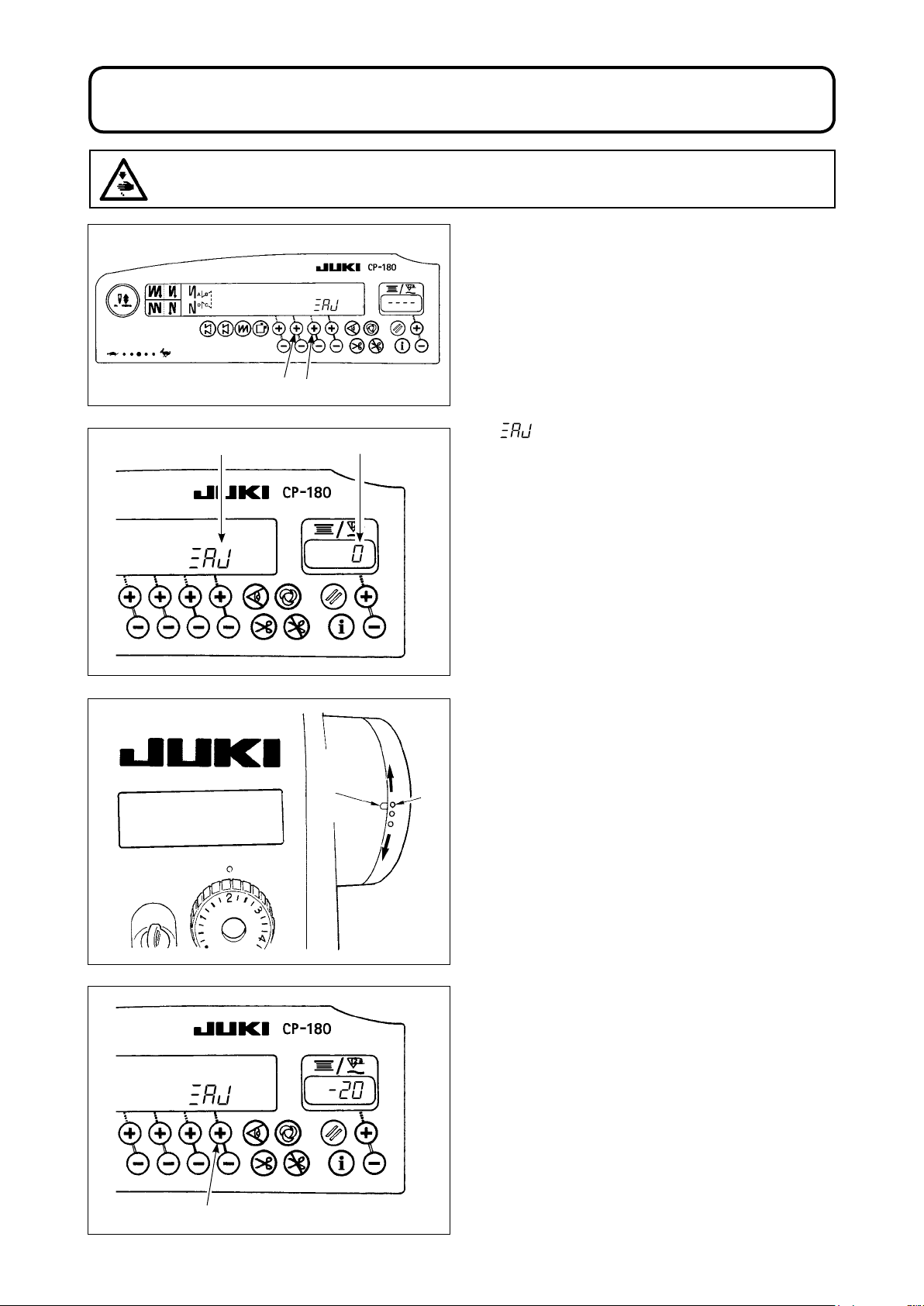
5. ADJUSTING THE MACHINE HEAD (DIRECT-DRIVE MOTOR TYPE SEWING MACHINE ONLY)
WARNING :
Be sure to perform the angle adjustment of the machine head by the operation below before using
the machine head.
1) Simultaneously pressing switch 1
turn ON the power sw
21
2) is displayed A
BA
mode is changed over to the adjustment mode.
3) Turn the handwheel by hand and angle B is dis-
played
has been detected.
(The value
in the indicator when the reference signal
is the reference value.)
itch.
in the indicator and the
and switch 2,
3
4) In this state, align the white dot 2 of the hand-
wheel with the concave 3 of the handwheel
cover as shown in the gure.
2
5) Press switch 4 to nish the adjustment work.
(The value is the reference value.)
4
- 3 -
Page 6
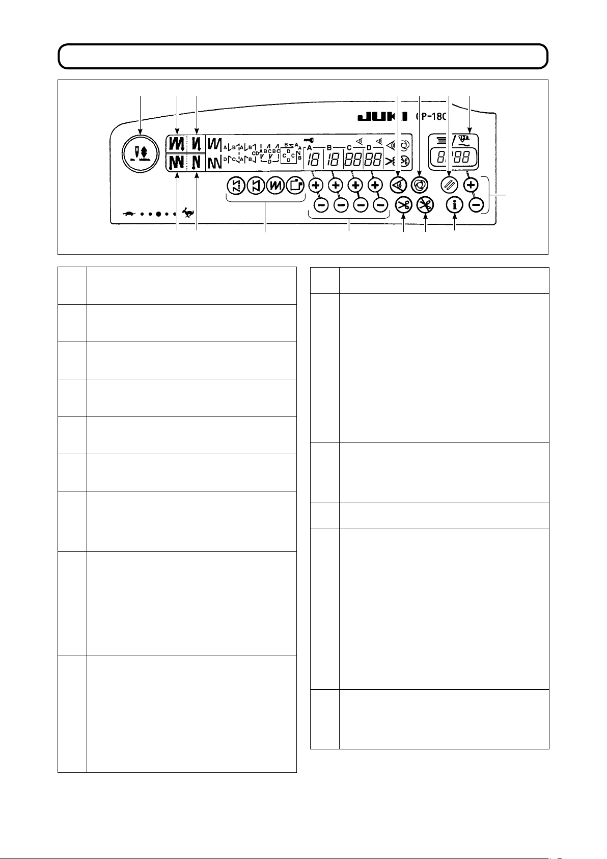
6. EXPLANATION OF THE CONTROL PANEL
!4
2 4 8
3 5
Pattern selector switch
1
• Used for selecting a pattern from among the
four different patterns.
Double reverse stitching (for start) switch
2
• U
sed for turning ON/OFF the double reverse
stitching for start.
Double reverse stitching (for end) switch
3
• U
sed for turning ON/OFF the double reverse
stitching for end.
Automatic reverse stitching (for start) switch
4
• U
sed for t u r n i n g O N / O FF the autom a t i c
reverse stitching for start.
Automatic reverse stitching (for end) switch
5
• U
sed for t u r n i n g O N / O FF the autom a t i c
reverse stitching for end.
Switches for setting the number of stitches
6
• Used
Material edge sensor ON/OFF switch
7
• R
• Used for setting whether or not the material
One-shot automatic stitching switch
8
• R
• Start the sewing machine with this switch, and
Automatic thread trimming switch
9
• R
• Even keep depressing the front part of the
for setting the number of stitches to be
sewn in processes A through D.
endered effective when the material edge
sensor is installed on the machine.
edge sensor is used during sewing.
endered effective when the material edge
sensor is installed on the machine or when
the sewing machin e is operated under the
constant-dimension stitching mode.
the sewing machine will run automatically until
the material edge is detected or the end of a
constant-dimension stitching is reached.
endered effective when the material edge
sensor is installed on the machine or when
the sewing machin e is operated under the
constant-dimension stitching mode.
pe dal, the sensor can det ect the m ater ial
edge, or after the completion of the constantdimension stitching mode, the machine will
automatically perform thread trimming.
!1
!0
!2
!5
7
61
Thread trimming prohibition switch
!0
•
Used for prohibiting thread trimming at any occasion.
Bobbin thread counter/thread trimming counter
!1
• Bobbin thread counter/thread trimming counter
can be changed over by the function of the control
box main body.
Bobbin thread counter :
icates the amount of bobbin thread while
• Ind
counting it by subtracting from the set value.
• When the bobbin thread remaining amount
detecting device is installed on the machine, the
counter indicates the number of times of detecting.
Thread trimming counter :
• Every t
counter value is added.
Bobbin counter reset switch
!2
sed for returning the value shown on the
• U
bobbin thread counter to the initial value.
• When the thread trimming counter is selected,
it is reset to [0].
Bobbin thread amount setting switch
!3
• Used for sett
Needle up/down compensation switch
!4
• Used for performing needle up/down
compensation stitching.
[Changeover selection of needle bar stop position
when the pedal is in its neutral position]
• Pressing the needle up/down compensation
switch, turn ON the power to the machine, and
the needle bar stop position when the pedal is
in its neutral position is changed over to down
position/up position.
• Conrmation of the stop position can be
performed at the front cover of the control box.
When up position stop is specied : " nP UP
When down stop position is specied : " nP Lo "
Information switch
!5
sed f o r ca l l i ng th e pr o d u c tion s u p p o r t
• U
function and callin g th e on e-t ouc h se tti ng
(by keeping the switch held pressed for one
second.)
9
ime thread trimming is performed, the
ing the amount of bobbin thread.
!3
"
- 4 -
Page 7
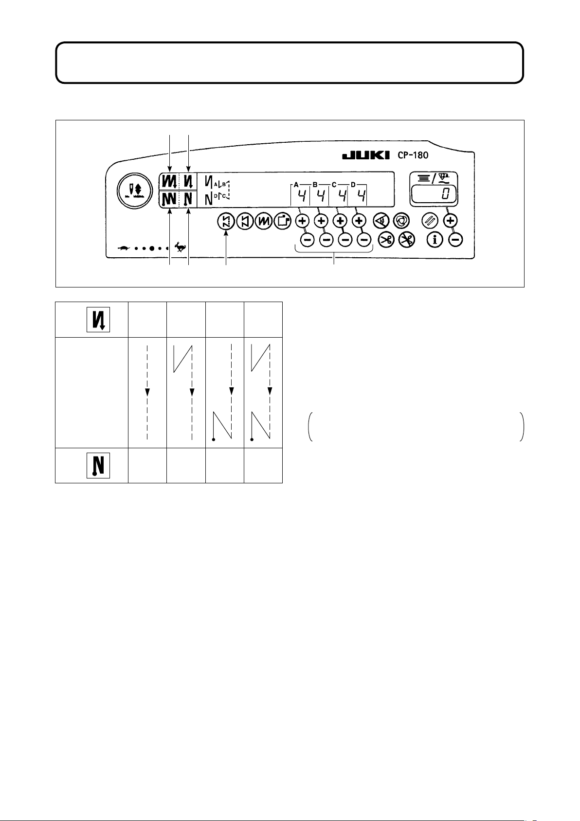
7. HOW TO OPERATE THE CONTROL PANEL FOR SEWING STITCHING PATTERNS
(1) Reverse stitching pattern
5 2
2
Sewing pattern
3
6 3
OFF ON OFF ON
A
B
C
D
OFF OFF ON ON
A
B
C
D
41
1) Press reverse stitching pattern switch 1 to
specify the reverse stitching pattern.
2) The reverse stitching pattern is selected, and the
number of stitches and data on reverse stitching
which have already been specied are shown on
the panel.
3) If you want to change the number of stitches,
operate the " + " or " - " switch of switches 4 for
setting the number of stitches A through D.
The range of the number of stitches that can be
changed : 0 to 19 stitches
4)
Four different stitching patterns can be performed
by matching the ON and OFF settings of automatic reverse stitching (for start) switch 2 and
automatic reverse stitching (for end) switch 3.
5) Furthermore, the double reverse stitching can be
selected by operating double reverse stitching
(for start) switch 5 and double reverse stitching
(for end) switch 6.
- 5 -
Page 8

(2) Constant-dimension stitching pattern
2
Sewing pattern
3
7 2
8 3
OFF ON OFF ON
A
B
CD
OFF OFF ON ON
CD
CD
B
A
A
B
CD
B
A
!0
41 5
6 9
1) Press constant-dimension stitching pattern
switch
on the control panel to select the
1
constant-dimension stitching pattern.
2) The constant-dimension stitching pattern is
selected. Now, the predetermined number of
stitches and the state of reverse stitching function are shown on the control panel.
3) To change the number of stitches of the process-
in the constant-dimension stitching pattern,
es
change the number of stitches for processes C
and D by operating switches 5 for setting the
number of stitches for processes C and D. Select
the reverse feed stitching accordingly. To change
the number of reverse-feed stitches, operate
switches 4 for setting the number of stitches for
processes A and B.
Adjusting range : A, B = to 19 stitches
C, D = 5 to 500 stitches
4) Four different kinds of stitching patterns can be performed according to the combination of ON/OFF setgs of automatic reverse stitching (for start) switch 2 and automatic reverse stitching (for end) switch 3.
tin
5) Furthermore, the double reverse stitching mode can be specied by operating double reverse stitching (for
start) switch 7 and double reverse stitching (for end) switch 8.
6) If automatic thread trimming switch 6 is turned ON, the sewing machine will automatically perform
thread trimming after it nishes the predetermined number of stitches between C and D. (If the automatic
reverse feed stitching (for end) is selected, the sewing machine will automatically perform thread trim-
ming after it nishes the automatic reverse stitching (for end) even when the automatic thread trimming
switch is not selected.)
If automatic thread trimming switch 6 is turned OFF, operate the touch-back switch after the completion
of processes C and D. Then the machine runs at a low speed (stitch compensation operation).
Also, if the pedal is returned to its neutral position and depressed its front part again, the sewing can be
continued regardless of the setting of number of stitches.
7) If thread trimming prohibiting function 9 is chosen, the machine will stop with the needle up without per-
forming thread trimming.
8) If one-shot automatic stitching function !0 is chosen, the machine will automatically perform sewing at a
stretch, at the specied speed by depressing the front part of the pedal.
- 6 -
Page 9

(3) Overlapped stitching pattern
2 31 4
1) Press overlapped stitching pattern switch
1
to
specify the overlapped stitching pattern.
A
C C
2) The overlapped stitching pattern is selected, and
the number of stitches and data on overlapped
stitching which have already been specied are
shown on the panel.
If you want to change the number of stitches,
3)
operate number of stitches setting switches 2
B
B
for processes A through C, and to change the
number of repeated processes, operate the " + "
D
or " - " switch of switch 3 for setting the number
of processes D.
The range of the number of stitches A, B and C
that can be changed : 0 to 19 stitches.
The range of the number of processes D that
can be changed : 0 to 9 times.
4) Depress the front part of the pedal once, and the sewing machine will repeat the normal stitching and re-
verse stitching by the predetermined times. Then, the sewing machine will automatically make the thread
trimmer actuate and will stop to complete the overlapped stitching procedure. (The one-shot automatic
stitching cannot be turned OFF.)
5) If thread trimming prohibiting function 4 is chosen, the machine will stop with the needle up upon com-
pletion of the overlapped stitching procedure without performing thread trimming.
- 7 -
Page 10

(4) Rectangular stitching pattern
1
Sewing pattern
6 2
7 3
OFF ON OFF ON
A
B
D
C
C
A
A
B
D
B
C
41 5
C
A
C
!0
8 9
B
D
C
A
B
A
B
C
D
C
1
D
OFF OFF ON ON
D
1) Press rectangular stitching pattern switch 1 on the control panel to select the rectangular st
D
D
itching pattern.
2) The rectangular stitching pattern is selected. Now, the predetermined number of stitches and other sewing
data are shown on the control panel.
3) To change the number of stitches of the processes in the rectangular stitching pattern, operate switches 5
(for processes C and D) to change the number of stitches for processes C and D.
Select the reverse feed stitching accordingly. To change the number of reverse-feed stitches, operate
switches 4 for setting the number of stitches for processes A and B.
(Adjustable range : A, B = 0 to 19 stitches, C, D = 0 to 99 stitches)
4) Four different kinds of stitching patterns can be performed according to the combination of ON/OFF set-
tings of automatic reverse stitching (for start) switch 2 and automatic reverse stitching (for end) switch 3.
5) Furthermore, the double reverse stitching mode can be specied by operating double reverse stitching (for
start) switch 6 and double reverse stitching (for end) switch 7.
At each step the sewing machine automatically stops after sewing the predetermined number of stitches.
At this time, if the touch-back switch is operated, the sewing machine runs at a low speed (stitch compen-
sation operation). Also, at the last process, if the pedal is returned to its neutral position and depressed its
front part again, the sewing can be continued regardless of the setting of number of stitches.
6) If automatic thread trimming switch 8 is turned ON, the sewing machine will automatically perform thread
trimming after the completion of the last process. (If the automatic reverse stitching (for end) is selected,
the sewing machine will automatically perform thread trimming after it nishes the automatic reverse stitch-
ing (for end).)
7) If thread trimming prohibiting function 9 is chosen, the machine will stop with the needle up without per-
forming thread trimming.
8) If one-shot automatic stitching function !0
stretch until the number of stitches specied is reached, at the predetermined sewing speed by depr
is chosen, the machine will automatically perform sewing at a
essing
the pedal while the sewing machine is engaged in the sewing of process C or D. The machine performs
thread trimming in the last process of one-shot automatic stitching pattern.
9) For the sewing machine equipped with an auto-lifter, the presser foot will automatically go up after the com-
pletion of each sewing process.
- 8 -
Page 11

8. ONE-TOUCH SETTING
A part of function setting items can be easily changed in the normal sewing state.
WARNING :
For the setting of functions other than those covered in this part, refer to "Instruction manual for the
SC-920".
< One-touch setting procedure >
1
) Keep switch 1 held pressed one second to en-
ter the funct
2) The set value can be changed by using switch 2.
3) To return to the normal sewing state, press
switch 1.
ion setting mode.
2
1
* Wiper function ( )
: Wiper does not operate after thread trimming
: Wiper operates after thread trimming
Th e setting is confirmed by pressing
switch 1.
9. PRODUCTION SUPPORT FUNCTION
The production support function consists of two different functions (five different modes) such as the
production volume management function, operation measuring function. Each of them has its own production
support effect. Select the appropriate function (mode) as required.
< Production volume management function >
•
Target No. of pcs. display mode [F100]
• Target/actual No. of pcs difference display mode [F200]
The target number of pieces, actual number of pieces and the difference between the target and actual
number of pieces along with the operation time are displayed to notify the operators of a delay and advance
in real time. Sewing machine operators are allowed to engage sewing while constantly checking his/her
work pace. This helps raise target awareness, thereby increasing productivity. In addition, a delay in work
can
be found at an early stage to enable early detection of problems and early implementation of corrective
measures.
< Operation measuring function >
Sewing machine availability rate display mode [F300]
•
• Pitch time display mode [F400]
• Average number of revolutions display mode [F500]
Sewing machine availability status is automatically measured and displayed on the control panel. The data
obtained can be used as basic data to perform process analyses, line arrangement and equipment efciency
checkup.
- 9 -
Page 12

2
2
3
3
6
1
< To display the production support modes >
1) Keep switch 1 held pressed (for one second)
in
the normal sewing state to call up the one-touch
setting screen.
4
2)
Then, press switch 2 on the one-touch sett
screen to display/hide the production support modes.
ing
3) Select the mode to be displayed/hidden by
1
pressing switch 3.
4) ON/OFF of the display can be changed over by
pressing switch 4.
5) To return to the normal sewing state, press
switch 1.
F100 to F500 modes have been factory-set
to HIDE at the time of delivery.
< Basic operation of the production support modes >
BA
Sewing can be perfor m e d w i t h t he production
support data displayed on the control panel.
1) When switch 1
is pressed in the normal sewing
state to enter the production support mode.
2) Production support function (F100 to F500) can
be changed over by pressing switch 2.
5
4
3) The data with an asterisk mark (*1) in Table 1
"
Display of modes" can be changed by pressing
switch 3. The data with an asterisk mark (*2)
can be changed by switch 4 or switch 5.
4) Refer to the Table 2 "Mode resetting operation"
for the resetting procedure of data.
5) To return to the normal sewing state, press
switch 1.
Table 1: Display of modes
Mode name Indicator
Target No. of pcs. display mode
(F100)
Target/actual No. of pcs.
ifference display mode
d
(F200)
Sewing machine availability
rate display mode
(F300)
Pitch time display mode
(F400)
A v e r a g e n u m b e r o f
ions display mode
revolut
(F500)
A
Actual No. of pcs.
(Unit : Piece)
(*1)
Difference between target No.
of pcs and actual No. of pcs
(Unit : Piece)
(*1)
icator
Ind
Target No. of pcs.
(Unit : Piece)
(*2)
Target pitch time
(Unit : 100 msec)
(*2)
S e w i n g m a c h i n e
av a i la b i li t y r a t e in th e
previous sewing
(Unit : %)
Pitch time in the previous
sewing
(Unit : 1 sec)
Average number of revolutions
in the previous sewing
(Unit : sti/min)
- 10 -
B
Indicator
(when switch 4
is pressed)
D i s p l a y o f a v e r a g e
availability rate of sewing
machine
(Unit : %)
Display of average pitch
time
(Unit : 100 msec)
Display of average number
of revolutions
(Unit : sti/min)
B
or switch
-
-
6
Page 13

Table 2: Mode resetting operation
Mode name
Target No. of pcs. display mode
(F100)
arget/actual No. of pcs. difference
T
display mode
[F200]
Se wing machine ava ilab ilit y rat e
display mode
(F300)
Pitch time display mode
(F400)
Averag e nu m b er of re v o l u tions
display mode
(F500)
Switch
6
(held pressed for 2 seconds)
Resets the actual number of pieces.
Resets the difference between target
number of pieces and actual number
of pieces.
Resets the actual number of p
Resets the difference between target
number of pieces and actual number
of pieces.
esets average availability rate of
R
sewing machine
Resets average p
R e s e t s a v e r a g e n u m b e r o f
ions of sewing machine
revolut
itch time
ieces.
Switch
6
(held pressed for 4 seconds)
-
-
Resets average availability rate of
sewing machine.
Resets average pitch time.
R e s e t s a v e r a g e n u m b e r o f
revolutions of sewing machine.
Resets average availability rate of
sewing machine.
Resets average pitch time.
R e s e t s a v e r a g e n u m b e r o f
revolutions of sewing machine.
Resets average availability rate of
sewing machine.
Resets average pitch time.
R e s e t s a v e r a g e n u m b e r o f
revolutions of sewing machine.
2
1
3
< Detailed setting of production volume manage-
ment function (F101, F102) >
• When switch 1 is held pressed (for three sec-
onds) under the target No. of pcs. d
isplay mode
(F100) or the target/actual No. of pcs. difference
display mode (F200), the detailed setting of the
production volume management function can be
carried out.
• The setting state of the number of times of
thread trimming (F101) and that of the target
achievement buzzer (F102) can be changed
over by pressing switch 2.
• The number of times of thread trimming for sew-
ing one piece of garment can be set by pressing
switch 3
in the setting state of the number of
times of thread trimming (F101).
• It is possible to set whether the buzzer sounds
or not when the actual number of pieces has
reached the target volume by pressing switch
in the setting state of the target achievement
3
buzzer.
- 11 -
Page 14

10. HOW TO USE THE BOBBIN THREAD COUNTER
The machine detects the number of stitches. The preset value on the bobbin thread counter is subtracted in
accordance with the number of stitches detected.
setting No. 7, bobbin thread count down unit.)
0 → -1 ", the buzzer peeps three times to warn the operator that the time to change the bobbin thread has come.
(Subtraction is made according to the setting of function
When the value on the counter becomes a minus value as " 1 →
2
to return the value indicated on bobbin thread
counter 2 to the initial value (it has been factory-set to "0" at the time of delivery).
1) Press bobbin thread counter reset switch 1
The bobbin thread counter cannot be reset
3
2) Specify an initial value using bobbin thread
amount setting switch 3.
When keeping pressing the switch, the change-
1
over speed is increased.
< Initial value on the bobbin thread counter for reference >
3) Once the initial value is specied properly, start
the sewing machine.
4)
When a minus value is shown on the counter and the
buzzer peeps three times, replace the bobbin thread.
5) After the bobbin thread has been properly replaced, press bobbin thread counter reset switch
1
ter to the initial value. Now, re-start the sewing
machine.
6) If the remaining amount of bobbin thread is excessive or the bobbin thread runs out before the
The table below gives the initial setting values for
reference when the bobbin is wound with thread
to the extent that the pinhole in the outside of the
bobbin case is reached as shown in the gure given
bobbin thread counter indicates a minus value,
adjust the initial value appropriately using the “+”
or “-“ switch of bobbin thread adjustment switch
3
above.
If the remaining amount of bobbin thread is excessive
Thread used
Polyester spun
thread #50
Cotton thread
#50
Length of thread wound
round the bobb
36m
31m
in
Thread tension rate 100 %
Value on bobbin
thread counter
1200 (stitch
length : 3 mm)
1000 (stitch
length : 3 mm)
If the remaining amount of bobbin thread is insufcient
… Decrease the initial value using the “-“ switch.
1. Uneven performance may occur in
※ Actually, the bobbin thread counter is affected
by the material thickness and the sewing speed.
So, adjust the
initial value of the bobbin
counter in accordance with the operating conditions.
thread
2.
So, be sure to use the device after carefully
during sewing. In this case, make the
thread trimmer actuate once.
to return the value on the bobbin thread coun-
.
… Increase the initial value using the “+” switch.
accordance with the winding way of
thread or the thickness of materials and
it is necessary to set the thread trimming
amount with some surplus.
If the bobbin thread counter is used
in combination with the bobbin thread
remaining amount detecting device, the
bobbin thread counter indicates the number
of detections of the bobbin thread remaining
amount detecting device.
reading the Instruction Manual for the
bobbin thread remaining amount detecting
device.
- 12 -
Page 15

11. HOW TO USE THE THREAD TRIMMING COUNTER
2
3
1
After selecting each item, be sure to perform updating of the function setting No.
When turning OFF the power without performing updating, the set contents are not changed.
For the updating procedure, refer to "18. FUNCTION SETTING SWITCH" p.15.
4) When reset switch 1 is pressed, the contents of indication 2 will be reset to " 0 ".
5) When modifying the count value, increase/decrease the value with setting switch 3.
Bobbin thread counter indication can be changed
over to thread trimming counter (simplified sewing
counter) indication by the operation below.
1) Function setting No. 6 Turn OFF the setting of
bobbin thread counter function. .
( 0 : off / 1 : on )
2) Function setting No. 14 Turn ON the setting of
sewing counter function.
( 0 : off / 1 : on )
3) From turning ON the power next, the counter
indication works as the thread trimming counter.
Every time thread trimming is performed, the
counter indication is upped.
12. NEEDLE UP/DOWN COMPENSATION SWITCH
Ev ery time needle u p/down com pensation switch
1
is pressed, the needle goes up when it is in its
1
lowest position or comes down when it is in its highest
position. This compensates the stitch by a half of the
predetermined stitch length. However, note that the
machine does not run continuously at a low speed even
if you keep the switch held pressed. Also, note that the
needle up/down compensation switch is inoperative
after turning the handwheel by hand. Sewing of needle
up/down compensation operation does not make the
thread trimming operation operative.
W h e n e v er p r e s s in g t h e n e e d l e u p / d o w n
compensation switch 1 and turning ON the power to
the machine, the stop position when the pedal is in
its neutral position can be changed over.
Al s o, th e s p ec i fi e d s tat e a t t h is ti me ca n b e
conrmed at the panel.
(The contents shown there will be reflected when
turning ON the power after next time.)
- 13 -
Page 16

13. KEY LOCK FUNCTION
In order to prevent the specied data on the number of stitches or the processes (A, B, C and D) to be
changed by mistake, the setting switch can be locked. (Even with the setting keys locked, the pattern to be
sewn and the value on the bobbin thread counter can be changed.)
3
21
1) After the completion of the setting of data on the number of stitches, etc., turn OFF the power to the machine once.
2) Turn ON the power switch while simultaneously pressing automatic reverse stitching (for end) switch 1
and the " + " switch of number of stitches setting switch 2 for process A with ngers.
3) Key mark 3 is shown on the control panel. This completes the locking of keys.
(If the key mark is not shown on the control panel, carry out the aforementioned steps 1) through 3) again.)
* To release the keys from the locked state, perform again the steps 1) and 2).
(Once the key mark goes out, the keys are released from the locked state.)
14. ON/OFF SWITCH OF THE MATERIAL EDGE SENSOR
• When the material edge sensor, which is optionally available, is connected to the control panel, the ON/
OFF switch of the material edge sensor becomes effective.
• If the material edge sensor is specied, the sewing machine will automatically stop running or perform
thread trimming when the sensor detects the material edge.
If the material edge sensor is used in combination with the control panel, carefully read the Instruc-
tion Manual for the material edge sensor beforehand.
15. AUTOMATIC THREAD TRIMMING SWITCH
• This switch is used to automatically actuate the thread trimmer in a process where the sewing machine
automatically stops or when the material edge sensor is used.
(If the automatic reverse stitching (for end) is specied, the thread trimmer will actuate after the sewing
machine completes the automatic reverse stitching (for end).)
16. ONE-SHOT AUTOMATIC STITCHING SWITCH
• This switch is used, in the constant-dimension stitching mode, rectangular stitching mode, or in the
process where the material edge sensor is specied, to make the sewing machine automatically perform
sewing at the specied speed until the end of the process is reached only by driving the sewing machine
mode.
- 14 -
Page 17

17. THREAD TRIMMING PROHIBITION SWITCH
• This switch is used to temporarily make the thread trimming function inoperative.
The other performance of sewing machine is not affected by this switch.
(If the automatic reverse stitching (for end) is specied, the sewing machine will perform the automatic
reverse stitching at the end of sewing.)
• If the automatic thread trimming switch
ed, the machine will not perform thread trimming but stop with its needle up.
and the thread trimming prohibition switch are both speci-
18. FUNCTION SETTING SWITCH
A
2
1) Pressing function setting switch 1, turn ON the power to the machine.
2) The indication on the control panel is changed over to the function setting indication mode.
Function setting No. is shown at section A and the set value is shown at section B of counter indication section.
* The contents to be shown will be different according to the contents that were set in the last time.
3) Function setting No. can be changed over by operating switch 2.
4) Function set value (setting state in case of on/off) can be changed over by operating switch 3.
5) After completion of setting, by operating switch 2 the changed contents are stored in memory and re-
ected from the next time.
6)
For the details of the contents of function setting, refer to the Instruction Manual supplied with the control box.
B
3
1
Refer to SC-920 instruction manual for the function setting list, details of the function setting and the
optional input/output connector.
- 15 -
Page 18

19. OPTIONAL INPUT/OUTPUT SETTINGS
2
1) Select function number 12.
1
3
※※※※
※※※※
2) Select the items of " ", " " and " " using
switch 3.
[When "
Specify the displayed number of the input func-
tion setting connector by means of switch 2. Then,
specify the connector pin function corresponding to
the displayed number by means of switch 3.
Function code and abbreviation are displayed alter-
nately in 1.
[When " " is selected.]
Specify the displayed number of the output func-
tion setting connector by means of switch 2. Then,
specify the connector pin function corresponding to
the displayed number by means of switch 3.
Function code and abbreviation are displayed alter-
nately in 1.
* Refer to the Instruction Manual for the control
" is selected]
box for the displayed numbers of the function
setting connectors and the function codes.
- 16 -
Page 19

Example) The thread trimming function is assigned to the displayed number "
setting connector.
1) Select function number 12 according to the function
setting method.
" of the input function
ENGLISH
The lamps will light up alternately.
2) Select the item of
3) Select the displayed number "
by switch 3.
"
"
" by means of
switch 2.
4) Se
5) Fix
lect
" "
"
thread trimming function by switch 3.
"
thread trimming function by switch 2.
6) Set activation of signal by switch 3. If the thread
trimming is performed by
play to
by
"
High" signal, set the display to
, and if the thread trimming is performed
"
"
"
Low" signal, set the dis-
.
"
"
7) The above function is xed by switch 2.
8) The option input is ended by switch 2.
9) Select the item of
" "
by switch 3, and return to
the function setting mode.
- 17 -
Page 20

20. AUTOMATIC COMPENSATION OF NEUTRAL POINT OF THE PEDAL SENSOR
Compensation value
Whe n eve r th e pe d al s ens o r, spr ing , et c . a r e
replaced, be sure to perform following operation.
1)
Pressing the switch 1,
2) Compensation value is displayed in the indicator
as illustrated.
1. At this time, the pedal sensor does not
work properly if the pedal is depressed.
Do not place the foot or any object on
the pedal. Warning sound "blip" and the
compensation value is not displayed.
1
2. When any thing other than number is
displayed in the indicator, refer to the
Engineer’s Manual.
3) Turn OFF the power switch, and turn ON the
power switch again to return to the normal mode.
21. SETTING OF THE AUTO LIFTER FUNCTION
turn ON the power switch.
WARNING :
When the solenoid is used with the air drive setting, the solenoid may be burned out. So, do not
mistake the setting.
When the auto-lifter device (AK) is attached, this
function makes the function of auto-lifter work.
1)
Turn ON the power switch while pressing switch 1.
2)
LED display is turned to " " " " with "blip",
and the function of auto-lifter becomes effective.
3) Turn OFF the power switch and turn ON the
power switch again. The machine returns to the
normal motion.
4) Repeat the operation 1) to 3), and LED display
1
" " " " : Auto-lifter device becomes effective. Selection of the auto-lifter device of solenoid drive
(+33V) or of air drive (+24V) can be performed with switch 2.
(Changeover is performed to drive power +33V or +24V of CN37.)
" " " " : Solenoid drive display (+33V)
" " " " : Air drive display (+24V)
" " " " : Auto-lifter function does not work. (Standard at the time of delivery)
(Similarly, the presser foot is not automatically lifted when programmed stitching is completed.)
is turned to " " " ". Then, the function of
auto-lifter does not work.
1.
(If ON/OFF operation of the power is performed quickly, setting may be not changed over well.)
2. Auto-lifter is not actuated unless this function is properly selected.
3. When
To perform re-turning ON of the power, be sure to perform after the time of one second or more has passed.
" " " "
delayed at the start of sewing. In addition, be sure to select
not installed since the touch-back switch may not work.
is selected without installing the auto-lifter device, starting is momentarily
" " "
- 18 -
when the auto-lifter is
"
Page 21

22. INITIALIZATION OF THE SETTING DATA
All contents of function setting can be returned to the
standard set values.
1) Pressing all switches 1, 2 and 3, turn ON the
power switch.
2) " " is displayed on indicator with a "blip" to
start initialization.
3) The buzzer sounds after approximately one
second (single sound three times, "blip", "blip",
and "blip"), and the setting data returns to the
1 2
1. When you carry out the aforementioned operation, the neutral position correction value for the
pedal sensor is also initialized. It is therefore necessary to carry out automatic correction of the
pedal sensor neutral position before using the sewing machine.
(Refer "20. AUTOMATIC COMPENSATION OF NEUTRAL POINT OF THE PEDAL SENSOR" p.18.)
2. When you carry out the aforementioned operation, the machine-head adjustment values are also
initialized. It is therefore necessary to carry out adjustment of the machine head before using the
sewing machine.
(Refer "5.
3. Even when this operation is performed, the sewing data set by the operation panel cannot be
initialized.
ADJUSTING THE MACHINE HEAD
3
standard setting value.
Do not turn OFF the power on the way of
initializing operation. Program of the main
unit may be broken.
4) Turn OFF the power switch and turn ON the
power switch again to return to the normal mode.
" p.3.)
23. CHECKING PROCEDURE OF THE ERROR CODE
1) Turn ON the power switch with switch 1 held
pressed.
2) The latest error number is displayed on indicator
with blip.
3) Contents of previous errors can be checked by
pressing switch 2.
(When the procedure has reached the end, two alarm
sounds in single tone will be heard, "blip" "blip".)
1
2
- 19 -
 Loading...