

Page 1

INSTALLING THE SLIM LINE® INSTRUMENT SERIES PAGE 1 OF 14
REV B
Applicable to
J
P
Slim Line® Temperature, Pressure, and
I
Volt-Amp Instruments.
I 3 5 5
EGT °F
READ THIS FIRST
The following notes apply to a new installation. Read this section before proceeding.
a) The JPI warranty found in the back of this manual clearly states that JPI will replace defective parts under
warranty, but does NOT cover labor to remove or install any parts from or to the aircraft.
b) This installation will require some parts unique to your aircraft that are not supplied with the kit, (including
but not limited to tie-wraps, hoses and fittings). Acquire all the necessary parts prior to beginning the
installation.
c) This manual is applicable to temperature, pressure and volt-amp instruments. Refer only to those sections
that pertain to your particular instrument(s).
d) Determine the locations of all holes before drilling to ensure that nothing interferes with the probe, clamp,
clamp screw or wire.
e) Provide service loops at the instrument.
f) Power up and test the instrument before installing it in the instrument panel.
g) Thermocouple wire length is not critical. Trim to required length, allowing for service loops at the engine so
that the probe can be swapped to adjacent cylinder positions for troubleshooting purposes.
h) Dress all wires away from high temperature components such as exhaust stacks.
i) Never splice thermocouple wire using copper wire. Use only K-type thermocouple wire. Soldering
thermocouple wire is not recommended, but if you must, solder using zinc chloride flux such as Nokorode
brand – rosin flux won’t work.
j) Observe correct polarity on all probe wires. Connect like colors together (red to red [-], yellow to yellow
[+]). Two-terminal pressure sensors have no polarity restrictions.
k) The most common cause of probe problems is poor terminal crimps. Crimp ring terminals with AMP part
48518 crimp tool or equivalent.
l)
1) Installation Overview
The overall installation procedure is as follows:
1. Power the instrument on the bench to verify it was received in working order. Set the alarm limits, if
necessary.
2. Install the instrument in the instrument panel.
3. Install the probe or sensor in the engine compartment.
4. Connect the connectors to the instrument.
5. Run the wires from the instrument in the instrument panel through the fire wall to the engine
compartment. Dress the wires to the probe or sensor.
6. Cut the excess length off the wires and connect to the probe or sensor.
7. Verify instrument operation.
January, 1998
Page 2
INSTALLING THE SLIM LINE® INSTRUMENT SERIES PAGE 2 OF 14
REV B
J. P. INSTRUMENTS PO Box 7033 Huntington Beach, CA 92615
2) Initial Bench Check
Connect the red wire to +12V or +24 V and the black wire to power return. Verify that the display lights up. If
the alarm limit has to be changed, it will be easier to do it now before the instrument is installed in the aircraft.
See the procedures near the end of this manual.
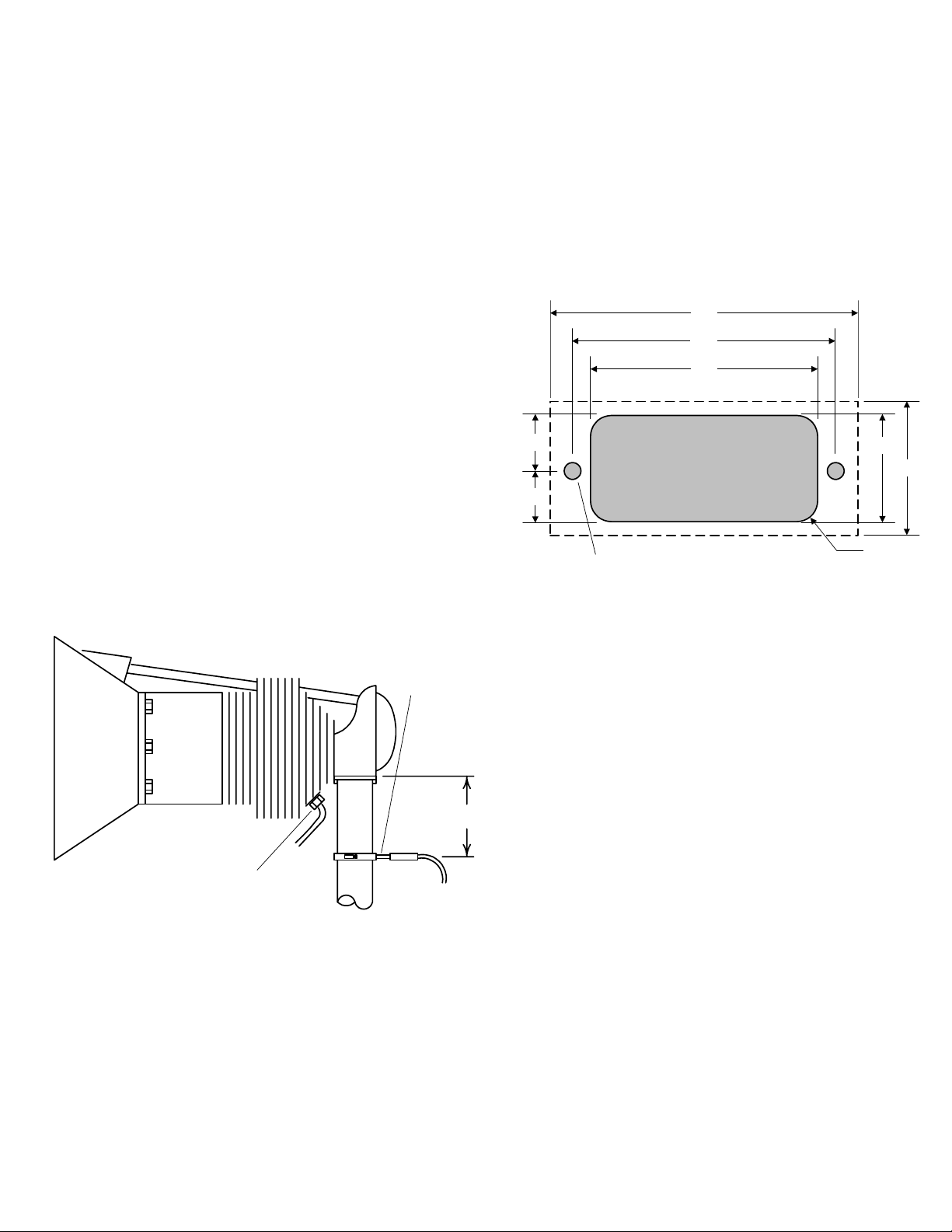
3) Installing the Instrument
Installation should be in accordance with Advisory Circular
AC43.13-1A. Identify the location for the instrument on the
instrument panel that can accommodate 2.75 inches wide by
2.75
2.35
2.03
1.2 inch high instrument, and 3.5 inches clearance behind
the instrument panel. Check the rear clearance with the
connectors attached to the instrument.
If more than one instrument is to be installed, the horizontal
center-to-center spacing must be at least 2.75 inches, and
the vertical center-to-center spacing must be at least 1.2
0.51
instrument panel cutout
0.46
0.97 ref
inches. Two instruments can be installed in a 3¼ inch hole.
Contact JPI for an optional bezel.
0.169 D 2 plcs
R0.125
4) Exhaust Gas Temperature (EGT) Probe
Installation
Determine the locations of all holes before
EGT probe
Drill no. 40
pilot hole,
then no. 30
hole.
exhaust stack
2" to 4"
CHT probe
distance from the flange as space permits. Careful matching of probe position will provide the best temperature
readings. Do not mount EGT probes in slip joints.
drilling to ensure that nothing interferes with the
probe, clamp, clamp screw or wire. The model
M-111 EGT probe will fit any engine having
existing holes in the exhaust stack of between
0.125 in. and 0.250 in. If no hole exists, drill a
0.125 in. hole and ream to fit. For multi-EGT
probe installations, it is important that each probe
be mounted a uniform distance from the exhaust
stack flange. A nominal distance of 2 to 4 inches
from the exhaust flange is recommended. If the
recommended distance is impractical due to
obstructions, slip joints or bends in the exhaust
system, then position the probes a uniform
1.20
Insert the probe in the exhaust stack hole such that the tip of the probe is in the center of the exhaust stream.
Tighten the stainless steel clamp and torque to 45 in/Lbs. Cut off excess strap close to the screw.
5) Turbine Inlet Temperature (TIT) Probe Installation
The standard TIT probe PN M111-T with a #48 clamp is placed in the exhaust stack accumulator to a maximum
depth of 1/2 inch and approximately 4 inches from the turbine inlet if possible, on the wastegate side of the
turbine.
Page 3
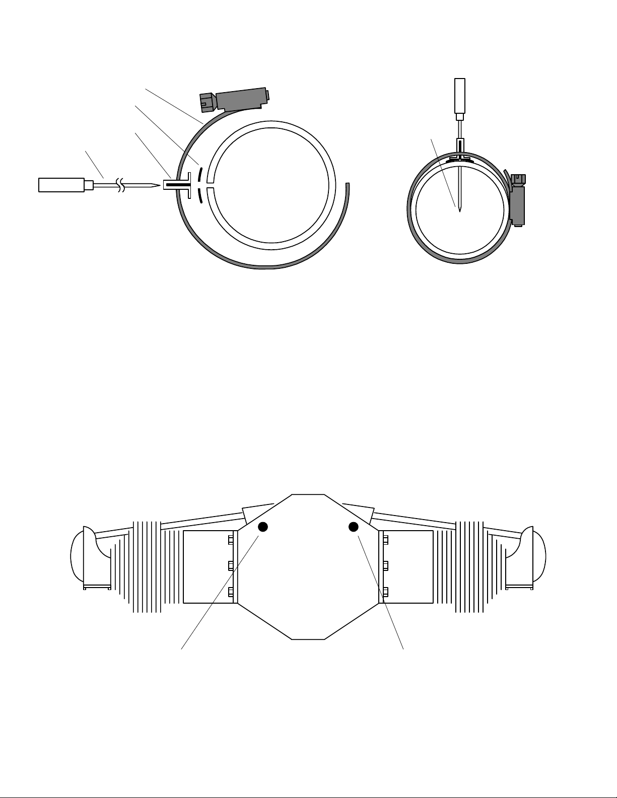
INSTALLING THE SLIM LINE® INSTRUMENT SERIES PAGE 3 OF 14
REV B
Clamp
Seal Washer
Thimble
note orientation
of slot
Probe
Position probe
in approximate
center of
exhaust
6) Cylinder Head Temperature (CHT) Probe, Bayonet Installation
The bayonet probe 5050-T has a captive 3/8-24 boss that is screwed into the base of the cylinder. The probe has
a screwdriver slot to facilitate tightening.
7) Cylinder Head Temperature (CHT) Probe, Spark Plug Gasket Installation
If there is no socket hole for the EGT probe on any cylinder or the aircraft is equipped with Tanis heaters, use a
spark plug gasket probe.
The spark plug gasket probe, PN M-113, replaces the standard copper spark plug gasket on one spark plug.
Choose the upper or lower spark plug, the one that provides the best correlation with the other temperature
probes. Due to the spark plug location, the gasket probe may read 25oF higher or lower than the factory probe.
Place the probe on the plug that receives the most direct cooling air.
8) Oil temperature (OIL) Probe Installation
front view
Oil Probe Location
Alternate Oil Probe
Location
Lycoming Engines
Lycoming Engines: The PN 400505-L probe is for all Lycoming direct drive engines and is installed in the
right (passenger side) front oil galley by removing the existing 1/8 NPT plug on the passenger side of the
engine and inserting the optional JPI oil probe supplied with the kit.
Page 4
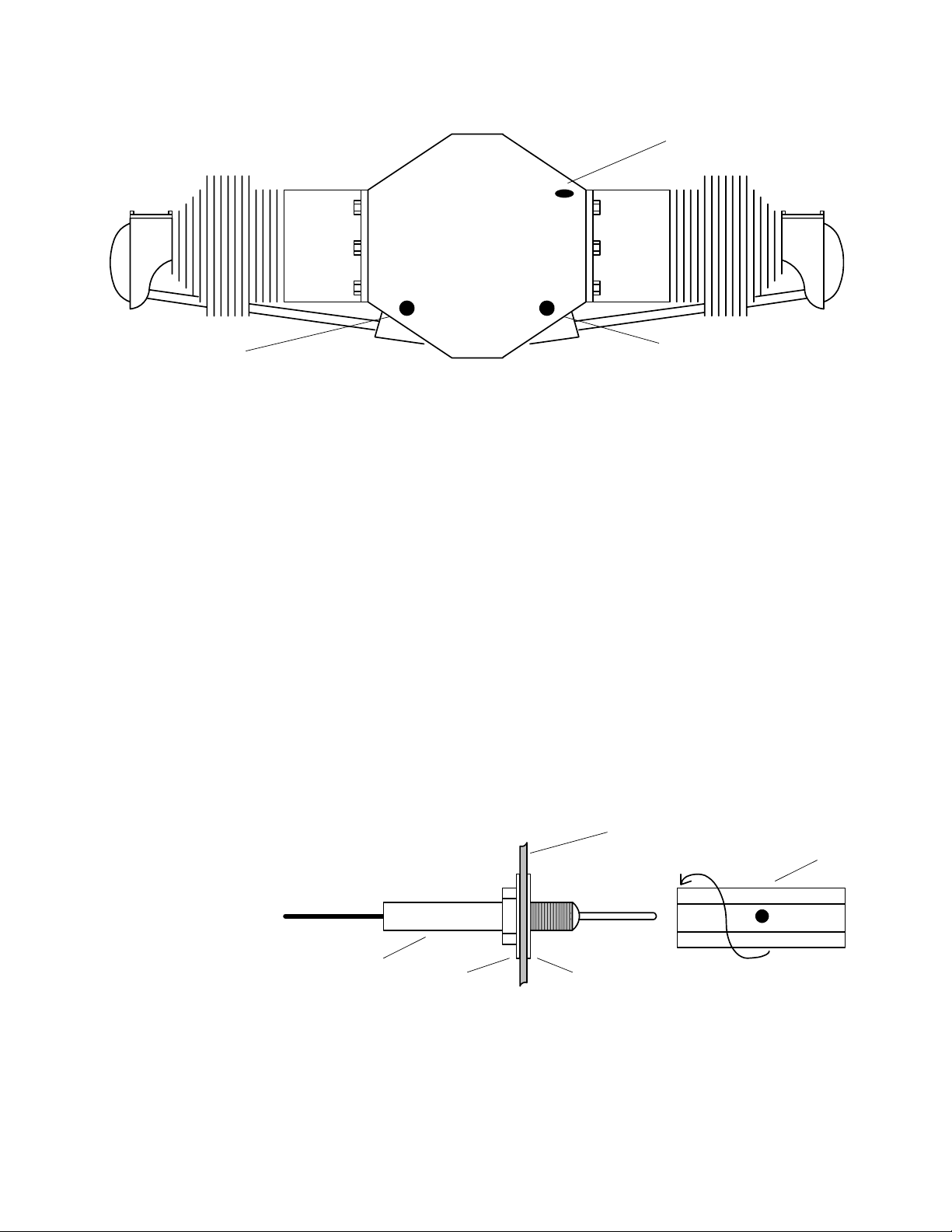
INSTALLING THE SLIM LINE® INSTRUMENT SERIES PAGE 4 OF 14
REV B
Alternate Oil Probe
Location
front view
Alternate Oil Probe
Location
Oil Probe Location
Continental Engines
Continental Engines: The PN 400505--C probe is for all Continental direct drive engines and is installed in the
left (pilot side) front oil galley by removing the existing 3/8 or 1/8 inch NPT plug (see figure above) located on
the front, pilots side of the engine. Insert the optional JPI oil probe supplied in the kit. For 3/8 inch NPT
installations, use the supplied brass adapter. An alternate location is on the top, front of the engine on the pilot’s
side, where the probe is inserted vertically. There are two 1/8 NPT plugs close together. Install the probe in the
position that is above and to the rear of the nearby position. Check for oil leaks before first flight.
9) Radial Engines
Radial engine exhausts require a larger EGT clamp (supplied) to fit the 2.5 inch exhaust pipe. The EGT probe is
installed using the same technique as on a Lycoming or Continental engine and should be placed between the
exhaust pipe flange and the accumulator at a distance of 2 to 3 inches from the engine exhaust flange. Cylinder
head temperatures are measured with a spark plug gasket type probe placed under the front sparkplugs. Front
spark plugs will read 15 to 20 degrees cooler than the rear plugs. Do not route the wire adjacent to or in the
ignition harness. Do not extend thermocouple wires with copper wire.
10) Outside Air Temperature (OAT) Probe Installation
Install the OAT probe, PN
400510 in the airframe
manufacturer’s
recommended location. If
aircraft sheet metal
shield tube
used to secure
probe
this information is not
available, place the OAT
probe in clean airflow such
as in a cabin air scoop or
probe
washer
washer
below the underside of the
wing away from engine heat or exhaust. In this case it is recommended that the installation be done similar to
the antenna installation instructions of AC 43.12-2a Acceptable Methods, Techniques and Practices.
The outside aluminum shield tube is used to both hold the probe in place and shield it from radiated heat. When
testing the OAT shield the sensor from direct sunlight and engine heat.
Page 5
INSTALLING THE SLIM LINE® INSTRUMENT SERIES PAGE 5 OF 14
REV B
11) Induction Air (IAT), Compressor Discharge Temperature Probe Installation
The Induction Air Temperature probe, (IAT), is installed just after the inter-cooler and the Compressor
Discharge Temperature (CDT) just before the inter-cooler. The probe is the same as an EGT probe and installed
similarly to an EGT probe. A large clamp is supplied to fit around the air port leaving the inter-cooler.
Alternately a 1/8 NPT fitting is available.
12) Carburetor (CRB) Probe Installation
Locate the access hole in the carburetor near the butterfly valve. Remove the screw plug and screw the CRB
probe into the carburetor throat.
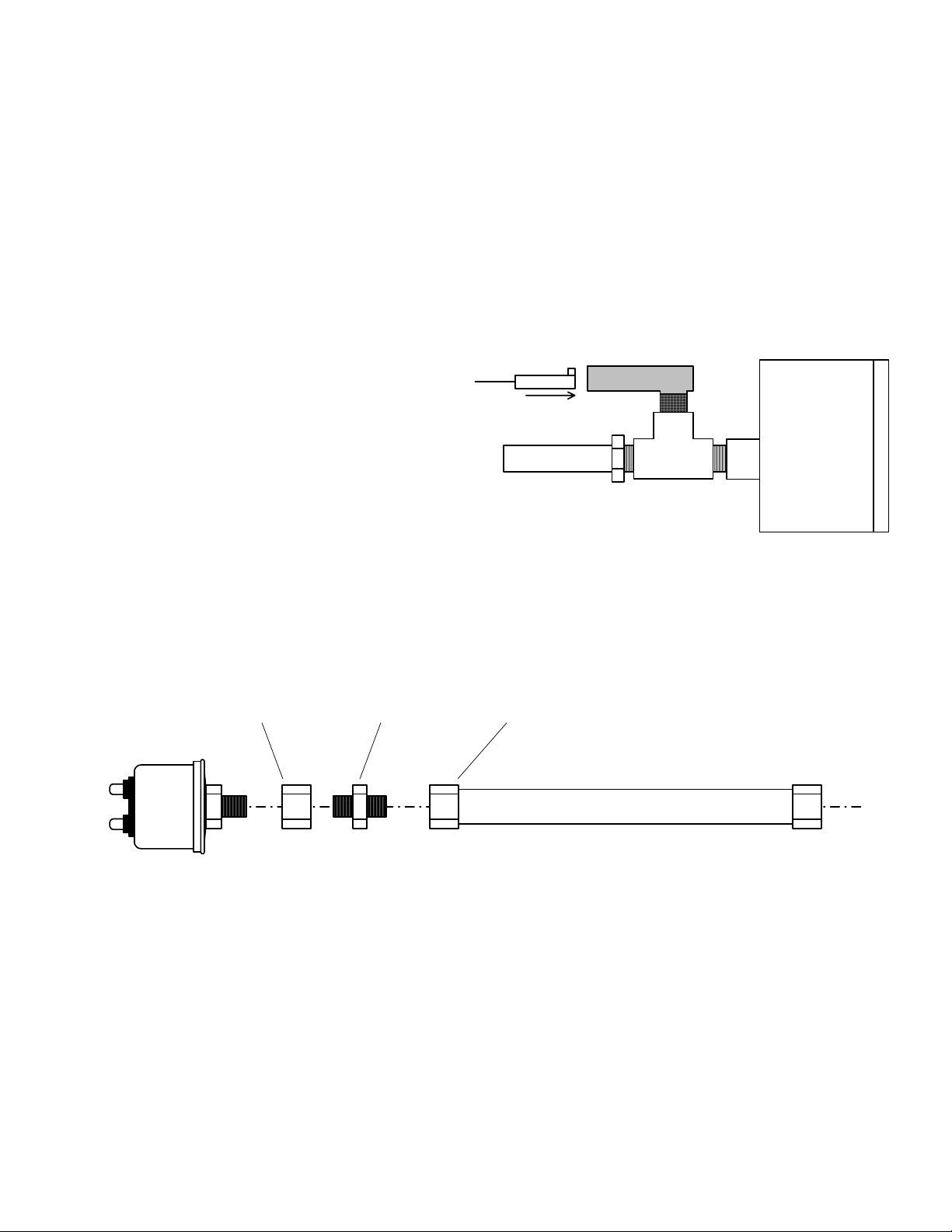
13) Manifold Pressure (MP) Sensor
Installation
Install a T-fitting (not supplied) in the aircraft’s MP
gauge line in the cockpit near the MP gauge. Install
connector
from engine
MP Sensor
T-fitting
MP gage
the MP sensor on the T-fitting. Later, you will
connect the MP sensor to the wiring using the 4-pin
connector supplied.
14) Oil Pressure, Fuel Pressure, Boom Pressure Sensor Installation
Mount the two ring-spade lugs to the two terminals on the sensor using the hardware supplied. Mount the
pressure sensor to the pressure line using a 6 inch flexible hose and fittings (not supplied) as depicted in the
drawing below. Use tie-wraps to mount the pressure sensor an engine mount structure. Do not mount the sensor
directly to the engine. Connect the other end of the hose to the existing pressure line, with a T-fitting if
necessary. Later, you will connect the pressure sensor to the two pressure sensor wires.
AN-910-1D
1/8 NPT coupling
pressure
sensor
AN-816-4D
1/8 NPT to flared
MIL-H-8794 hose
MS-24587 fitting (AEROQUIP 491, 2 req'd)
to engine
fitting
flexible tube 6 inch (AEROQUIP 303)
DO NOT MOUNT SENSOR DIRECTLY TO ENGINE
15) VOLT/AMP Shunt Installation
Install the current shunt in the electrical system.
Charge/Discharge configuration. The shunt can be installed between the master contactor and the main bus in
which case it will be in the ammeter configuration showing battery charge and discharge. Be sure that the
positive side of the shunt is connected to the main bus in the ammeter configuration. The alarm will be triggered
by a discharge condition.
Page 6

INSTALLING THE SLIM LINE® INSTRUMENT SERIES PAGE 6 OF 14
REV B
- BATT +
Master switch
Master switch
contactor
F G
B
Alternator
Bus
+
Starter Starter solenoid
external shunt
Ammeter Configuration
Load Meter Configuration. Or the shunt can be installed between the alternator output and the main bus in
which case it will be the load meter configuration showing alternator load (positive only). Be sure that the
negative side of the shunt is connected to the main bus in the load meter configuration. There is no alarm.
- BATT +
Master switch
contactor
F G
B
Alternator
+
Master switch
external shunt
Starter Starter solenoid
Load Meter Configuration
16) Connecting to the instrument
All temperature and pressure instruments Volt-Amp instrument
rear of instrument
connector
hook down
red
black
gray
rear of instrument
V-A switch
Bus
red
black
gray
white + shunt
gray - shunt
Page 7

INSTALLING THE SLIM LINE® INSTRUMENT SERIES PAGE 7 OF 14
REV B
Slim Line automatically accommodates both 14 and 28 volt electrical systems. Connect the power lead (red) to
a separate 2 amp circuit breaker (or 1 amp in-line fuse) connected to the avionics power bus. The avionics
master switch will then be used to turn off the instrument during engine start-up. If the panel lacks an avionics
master switch it is recommended that one be installed or a circuit breaker switch be provided to turn off the
Slim Line during engine start-up. Connect the ground return (black) to the avionics ground.
No connection to the aircraft dimmer system is required or permitted because the instrument dims automatically
with reductions in ambient light.
Remote Alarm Light
(150 ma max)
+12/24
The gray remote alarm wire is an open collector capable of
sinking up to 150 ma. This signal may be connected to a
unique alarm light or buzzer, or it may be connected to
other Slim Line instruments in a “wired-OR” configuration
to a common alarm light or buzzer. If it is not used, leave
the line open and tie-wrap the wire so that it does not
SIDE
VIEW
obstruct the freedom of control travel.
Plug the probe or sensor connector on the rear of the
SIDE
VIEW
instrument with the hook tab of the connector pointing
down. Be sure the connector is aligned with all the pins and
SIDE
VIEW
gray
wire
not shifted left or right.
The Volt/Amp instrument is configured without a
connector. Identify the wire bundle with the toggle switch
attached. The toggle switch should be mounted to the instrument panel near the instrument. The white wire
should be connected to the positive side of the shunt and the gray wire to the negative side of the shunt. See the
section, later, on VOLT/AMP shunt wiring.
17) Routing the Wiring
Leave adequate service loops at the instrument. Bundle all the probe and sensor wires together and route the
them from the instrument through the firewall using fireproof rubber grommets and flame retarding silicone.
Use an existing hole if possible. All wires must be routed away from high temperature areas (exhaust stacks,
turbochargers, etc.). Secure probe and sensor leads to a convenient location on the engine approximately 8 to 12
inches from the probe or sensor, being sure there is sufficient slack to absorb engine vibration and torque. It is
essential in routing the probe or sensor wire that this wire not be allowed to touch metal parts of the air-frame or
engine since abrasion will destroy the wire.
18) Temperature Probe Wiring
When cutting the pair of leads to the proper length to connect to the probes, leave enough slack in the wiring so
that probe may be interchanged to an adjacent cylinder if necessary for trouble-shooting and servicing.
Thermocouple wire length is not critical and should be trimmed to any length as required for a clean
installation.
The Temperature probe must be wired with the correct polarity. The temperature probe connects to its
temperature indicator with yellow jacket Teflon Chromel Alumel wire supplied. Strip the wires as shown below
-observing color codes.
2 1/4"
Thermocouple wire harness
red
yellow
1/4" 1 1/2"
Fold back wire
double before
crimping terminals
Page 8

INSTALLING THE SLIM LINE® INSTRUMENT SERIES PAGE 8 OF 14
REV B
Terminate each wire with a crimp-on ring terminal, provided. The ring terminals may be crimped with a
“service-type” tool, however AMP part number 48518 crimp tool is recommended. Verify the quality of each
crimp with a sharp tug on the wire. The terminal should be impossible to pull off when crimped correctly.
ring terminal
shrink tubing
shrink tubing
Place a ¼ x 4 inch sleeve over each pair of wires in the wiring. Connect the wire ring lug to the probe ring lug
using the supplied number 4 screws and nuts, placing the star washer between the ring lugs, not against the nut.
Important: place star waster between two ring
terminals and tighten nut and bolt as
to instrument
necessary
to probe
Slide the sleeve over the joint and secure with three tie-wraps.
tie-wrap 3 places
1/4 x 4" sleeve
The most common installation problems are related to poor quality terminations.
19) MP Sensor Wiring
Use the four-conductor cable supplied with the kit. Plug the smaller connector onto the sensor.
1
to
Sensor
BLK
WHT
RED
GRN
BLK
GRN
WHT
RED
to
MP
instrument
Page 9

INSTALLING THE SLIM LINE® INSTRUMENT SERIES PAGE 9 OF 14
REV B
20) VOLT/AMP Shunt Wiring
Connect the white lead from the Slim Line instrument to the positive shunt terminal and the gray lead to the
negative shunt terminal. Optionally, you may install 1 amp fuses in series with the shunt sense wires. Do not
allow any other connection to the shunt. Do not power the Slim Line instrument from the shunt.
direction of positive current flow
+
SHUNT
1 amp optional fuse
2 plcs
gray -
white +
21) Oil Pressure, Fuel Pressure, Boom Pressure Sensor Wiring
If you have not already done so, install a ring-spade lug on each of the two pressure sensor terminals. Cut sensor
leads to length at the pressure sensor. Provide adequate service loop. Attach the supplied female spade lugs by
stripping and crimping a pin on each wire, and then inserting each pin onto the pressure sensor. There is no
polarity restriction on the two wires.
22) Specifications and Limitations
Environmental:
Passed TSO C43c
Power:
10 to 35 volts DC, 250 ma
Operating Temperature Range:
-40 to 195 °F
Display Size:
2.0 x 0.95 inches
Analog-Thermocouples:
Resolution: 1.0 °F
Accuracy: +
Calibration: K
Pressure Sensors:
Oil (0 to 150 psi)
Fuel (0 to 30 psi)
Boom (0 to 150 psi)
MP (0 to 40 psi)
1.0 °F
Common Mode Range:
4v, rejection > 80db
+
Volt/amp:
Voltage 10-35 volts
Shunt 50 mv. at 60 amps or 100 amps
Page 10

INSTALLING THE SLIM LINE® INSTRUMENT SERIES PAGE 10 OF 14
REV B
2.70
2.00
J
P
0.50
0.45
I
0.95 ref
6-32 2 plcs
R0.125
2.35
1.18
3.25
TOP VIEW
SIDE VIEW
The conditions and test required for TSO approval of this article are minimum performance standards. It is the
responsibility of those desiring to install this article either on or within a specific type or class of aircraft to
determine that the aircraft installation conditions are within the TSO standards.
23) Weight and Balance Data
Weights below do not include customer supplied fittings, hoses, and other hardware.
TSO C43b, Slim Line instrument 3.0 oz. / 0.19 lbs.
MP, Oil P option 1.5 oz. / 0.094 lbs.
EGT probe M-111, IAT, CRB, TIT, OAT, OIL 2.0 oz. each / 0.125 lbs. each
CHT probe 5050T 1.5 oz. each / 0.094 lbs.
Oil P, Fuel P, Boom P sensor 4.0 oz. / 0.250 lbs.
Current shunt 3.5 oz. / 0.22 lbs.
Page 11

INSTALLING THE SLIM LINE® INSTRUMENT SERIES PAGE 11 OF 14
REV B
24) Parts List for Slim Line
Slim Line Instrument Ö
Included parts Ø
EGT
CHT
TIT/IAT
OIL
OAT
CRB
VOLT/AMP
OIL P
FUEL P
Boom P
MP
Slim Line Display, 2 mount. screws 1 1 1 1 1 1 1 1 1 1 1
Thermocouple Wire 8’ 8’ 8’ 8’ 8’ 8’
Molex 0.256” Connector Pins 2 2 2 2 2 2 2 2 2
Connector housing 1 1 1 1 1 1 1 1 1
Stainless Steel Clamp Thimble 1 1
Stainless Steel Exhaust Seal Washer 1 1
Stainless Steel Screw Clamp #24 1
Stainless Steel Screw Clamp #48 1
Ring Terminals 222222
Screws and nuts 6-32 X 1/4 2 2 2 2 2 2
Fiberglass tube ½ in. X 4 in. 1 1 1 1 1 1
Hookup Wire 2 conductor 8’ 8’ 8’
Cable, 4 conductor, two connectors 8’
Ring Spade Terminals 2 2 2
Female Spade Terminals 2 2 2
M-111 Thermocouple Probe 1 1
5050 Bayonet Probe, Spring loaded 1*
M-113 Gasket Probe, Spark Plug 1*
400505 -C or -L, OIL Probe 1
400510, OAT Probe 1
400128 Carburetor Probe 1
3060-17 Pressure Sender (30 psi) 1
3060-18 Pressure Sender (150 psi) 1 1
604010 MP Sensor 1
60 or 100 amp, 50 mv Shunt† 1
* CHT includes one bayonet or one gasket thermocouple probe. †not included – available from JPI
25) Setting the Alarm Limits
The Slim Line instrument is calibrated at the factory and should require no calibration in the field. However if
the instrument alarm limit must be changed for any reason, follow these steps.
Temperature and MP instruments Alarm Limit Set
++
0-12v
adjustable
source
20K
100
0-60
mv
Obtain a stable voltage source capable of generating 0 through 60
millivolts (0.060 volts). A useful source is an adjustable power supply
and a pair of dropping resistors as shown to the left. Apply the millivolt
source to the two center pins on the rear of the instrument. The positive
lead should be on the left as you look at the rear of the instrument.
Apply a fixed +12 volts to the instrument’s red power wire and ground
return to the black wire. Adjust the millivolt source until the reading on
Page 12

INSTALLING THE SLIM LINE® INSTRUMENT SERIES PAGE 12 OF 14
REV B
the front is at the desired red-line. Adjust the alarm pot until the two red alarm lights just turn on or off. This is
the correct setting for the alarm limit.
Temperature instrument MP instrument
rear of instrument
+
zero set (DO NOT ADJUST)
high set (DO NOT ADJUST)
alarm set
red
black
gray
high set (DO NOT ADJUST)
rear of instrument
nc + - nc
zero set
alarm set
Oil Pressure, Fuel Pressure and Boom Pressure Instruments Alarm Limit Set
Connect a 250 ohm linear variable resistor across the two pins
on the rear of the instrument. Apply +12 to the instrument’s
red power wire and ground return to the black wire. Adjust the
rear of instrument
variable resistor until the reading on the front is at the desired
red-line. Adjust the alarm pot until the two red alarm lights
just turn on or off. This is the correct setting for the alarm
limit.
Volt/Amp Instrument Adjustment
zero (DO NOT ADJUST)
To adjust the Volt/Amp instrument, follow this
procedure. Connect the red power lead, the gray
shunt lead (not the gray alarm indicator lead)
and the white shunt lead together and to a +12 or
rear of instrument
amps set
volts
set
+24 volt source. Connect the black lead to the
power return. Connect an external voltmeter
between the + voltage source and return. Set the
toggle switch to the voltage setting and adjust
the volts set pot until the voltage on the Slim
V-A switch
Line instrument matches the voltage on the
external voltmeter.
w
Set the toggle switch to amps setting and adjust
h
the amps set pot to indicate zero amps.
alarm set
g
ra
y
i
t
e
+
red black
-
s
h
u
n
t
s
h
u
n
t
red
black
gray
red
black
gray
gray
grd
+12
power supply
26) Manifold Pressure Calibration
The manifold pressure must be calibrated to the
ambient air pressure. You must adjust the instrument to
the current ambient barometric pressure. This setting is
not the same as the altimeter setting that you receive
from ATIS or unicom. It will vary with field elevation.
The engine must not be running.
If your field elevation is less than 500 feet, you can set
your altimeter to zero feet and read the ambient MP on
rear of instrument
zero set
high set (DO NOT ADJUST)
alarm set
red
black
gray
Page 13

INSTALLING THE SLIM LINE® INSTRUMENT SERIES PAGE 13 OF 14
REV B
the Kollsman window. Or use the chart below to calculate the MP FACTOR. Multiply this MP FACTOR by the
altimeter setting that you receive from ATIS or unicom. For example if the field elevation is 1700 ft and the
current altimeter setting is 30.1, the MP FACTOR is determined to be 0.9400 from the table. Multiply 30.1 x
0.9400 to obtain the ambient MP of 28.29.
Adjust the zero set pot as shown on the above diagram so that the MP reading is the same as the ambient MP
determined above.
Field Elev MP FACTOR Field Elev MP FACTOR Field Elev MP FACTOR Field Elev MP FACTOR Field Elev MP FACTOR
-500 1.0182
-400 1.0145
-300 1.0109
-200 1.0073
-100 1.0036
0 1.0000
100 0.9964
200 0.9928
300 0.9892
400 0.9856
500 0.9821
600 0.9785
700 0.9750
800 0.9714
900 0.9679
1000 0.9644
1100 0.9609
1200 0.9574
1300 0.9539
1400 0.9504
1500 0.9469
1600 0.9435
1700 0.9400
1800 0.9366
1900 0.9332
2000 0.9298
2100 0.9264
2200 0.9230
2300 0.9196
2400 0.9162
2500 0.9129
2600 0.9095
2700 0.9062
2800 0.9028
2900 0.8995
3000 0.8962
3100 0.8929
3200 0.8896
3300 0.8863
3400 0.8830
3500 0.8798
3600 0.8765
3700 0.8733
3800 0.8700
3900 0.8668
4000 0.8636
4100 0.8604
4200 0.8572
4300 0.8540
4400 0.8508
4500 0.8477
4600 0.8445
4700 0.8414
4800 0.8382
4900 0.8351
5000 0.8320
5100 0.8289
5200 0.8258
5300 0.8227
5400 0.8196
5500 0.8165
5600 0.8135
5700 0.8104
5800 0.8074
5900 0.8043
6000 0.8013
6100 0.7983
6200 0.7953
6300 0.7923
6400 0.7893
6500 0.7863
6600 0.7833
6700 0.7804
27) Warranty
J. P. Instruments, Inc. (JPI), warrants all parts in your new Slim Line to be free from defects in material and
workmanship under normal use. Our obligation under this warranty is limited to repair or exchange of any
defective part of this unit if the part is returned, shipping prepaid, within two years for electronics and one year
for probes from the date of original purchase. Installation labor is the responsibility of the aircraft owner.
Homebuilt aircraft warranty starts when the aircraft is certified for flight. Replacement parts carry a warranty
for the balance of the warranty period.
Under this warranty, JPI is not responsible for any service charges, including removal, installation, nor any
other consequential damages. JPI incurs no obligation under this warranty unless a Warranty Registration
Certificate describing the warranted product has been completed and mailed to JPI with all information
requested.
This warranty is void on any product which has been subject to misuse, accident, damage caused by negligence,
damage in transit, handling or modification which, in the opinion of JPI, has altered or repaired the product in
any way that effects the reliability or detracts from the performance of the product, or any product whereon the
serial number has been altered, defaced, effaced or destroyed.
This warranty is in lieu of all other warranties expressed or implied and other obligations of liability on JPI’s
part, and it neither assumes nor authorizes any other person to assume for JPI any other liability in connection
with the sale of JPI products.
To initiate this warranty, the aircraft owner must submit a completed warranty card to JPI. JPI will initiate the
warranty from the date of original purchase. Any replacement parts carry a warranty that extends for the balance
of the period of the original warranty. For homebuilt aircraft the warranty starts when the aircraft is certificated
for flight and noted on the warranty card.
Page 14

INSTALLING THE SLIM LINE® INSTRUMENT SERIES PAGE 14 OF 14
REV B
28) Troubleshooting
a) A negative temperature reading (- in front of the number) indicates reverse polarity on the red and yellow
thermocouple wire to probe.
b) Ohmmeter check. (Temperature instruments only) Remove the connector from the rear of the instrument
and measure the resistance of the probe lead pair. The reading should be about 10 ohms. At the connections
between the probe and the wiring in the engine compartment, the resistance should be about 2 ohms.
c) Ohmmeter check. (Oil pressure, Fuel pressure and Boom pressure instruments only) Measure the
resistance of the pressure sensors at the two terminals. With no pressure applied the resistance should be
about 10 ohms. Full pressure should read about 200 ohms, with intermediate pressures in between.
d) Temperature reading varying rapidly. Verify that the Instrument is grounded at the engine block for
single engine installations. If an adapter probe is being used insure that it is screwed in tightly. Remove the
factory original probe that is in the adapter and note if problem is resolved. If so an resistive ground exists
between the engine and the adapter probe. Check for a poor quality crimp between the probe and wiring.
e) Ammeter doesn’t read zero when no current is flowing. Check that there are no other connections to the
current shunt other than what is described in this manual. The Slim Line instrument should not be powered
from the shunt.
f) An alarm never occurs on the Volt/Amp indicator. Alarm will only show battery discharge. For a load
meter configuration, there will never be an alarm. There is no alarm for the voltage function.
Returns for repair should include a description of the problem symptom and conditions under which the
symptom occurred. Be sure to include your return address and phone number. Send instruments for repair to
J. P. Instruments, 3402-I West Mac Arthur, Santa Ana, CA 92704
29) Operation
The Slim Line instrument requires no operator interaction. Upon power-up, it will begin to display the measured
parameter. There are two red alarm indicators to the right of the numerical display. When an alarm condition is
detected, both indicators will flash simultaneously. These are the factory set alarm limits unless requested
otherwise.
o
EGT (Exhaust Gas Temperature Max. limit 2500
CHT (Cylinder Head Temperature Max. limit 600oF) 450oF
TIT (Turbine Inlet Temperature Max. limit 2500oF) 1650oF
OIL (Oil temperature Max. limit 600oF) 230oF
OAT (Outside Air Temperature Limit -40 to 300oF)
IAT/CRB (Induction Air Temperature Max. Limit 600
VOLT (Voltage, 0 to 40 volts.)
AMP (Amperes –60 to +60 or –100 to +100) Negative 0.5 amps or higher
OIL P, (Oil Pressure 0 – 150 psi) 15psi
FUEL P (Fuel Pressure 0 – 30 psi) 4 psi
Boom P (Boom Pressure 0 – 150 psi)
MP (Manifold Pressure 0 – 40 inHg) 36 inHg
F) 1650oF
No alarm
o
F.)
No alarm
No alarm
No alarm
The entire display dims automatically depending on the ambient lighting.
 Loading...