

J.P. Instruments EDM 730 Installation Manual

J.P.Instruments
for EGT-701 with Fuel Flow Option Page 1 of 14
Fuel Flow Installation Manual
Rev B : Date 03/14/97
Report # 503
Table of Contents
1. General 2
2. Initial Check Out 3
3. Installing the Fuel Flow Transducer 4
4. Route the Optional warning control line 5
5. Install the instrument in the panel 5
6. Route the Fuel Flow Transducer Wires 5
7. System Checkout 5
8. Specifications and Limitations 6
9. Pilot Programmable Modes 7
10. Drawing 700923 8
11. Drawing 700922 9
12. Drawing 700921 10
13. Drawing 700124 (
14. Drawing 700744 (
15. Drawing 700920 Installing the Fuel Flow Differential
excerpt from report #103, STC 2586NM)
excerpt from report 103, STC 2586NM)
11
12
13,14
Module FFDM-1 or FFDM-2
J.P.INSTRUMENTS
PO BOX 7033
HUNTINGTON BEACH CA 92704
Last printed 8/7/2008 1:58:00 PM

J.P.Instruments
for EGT-701 with Fuel Flow Option Page 2 of 14
Fuel Flow Installation Manual
Rev B : Date 03/14/97
Report # 503
EGT-701 with Fuel Flow Option
Installation Instructions
1…General:
A complete thorough familiarization and understanding of the system and this manual is necessary before commencing
the installation. All work must conform with A.C. 43.13.1A ch. 11 sec. 2, 3, 7. The accuracy of this instrument
depends entirely upon the accuracy of the data entered. A periodical checking of the actual fuel onboard will eliminate
the accumulation of errors due to evaporation leaks, etc.
Do not use the FXT-201 Flow Transducer on aircraft with a gravity feed system
Transducer (FXT-201) shipped with the EGT-701(),with Fuel Flow option Fuel Flow instrument is intended to be used
on aircraft equipped with fuel pumps. A gravity feed system requires the FXT-231 flow transducer.
Transducer Identification Markings
FXT-201 - Marked "20 l " on the top of the unit.
FXT-231 - Marked "231" on the top of the unit.
Installation of the EGT-701(),with Fuel Flow option on an aircraft with a fuel return line from the Carburetor
requires a FFDM-1, -2 Differential Module manufactured by from EI or JPI.
The placard "Do Not Rely on Fuel Flow Instrument to Determine Fuel Levels in Tanks" must be mounted on the
aircraft instrument panel near the EGT-701, ( ) with fuel flow option.
.
The standard Fuel
If the aircraft is equipped with a primary fuel flow, the following placard must be mounted on the aircraft
instrument panel near the EGT-701(),WITH FUEL FLOW OPTION( ): "Refer to Original Fuel Flow
Instrumentation for Primary Information".
do not obstruct the freedom of travel of arty controls.

J.P.Instruments
Fuel Flow Installation Manual
Report # 503
for EGT-701 with Fuel Flow Option Page 3 of 14
Rev B : Date 03/14/97
2…. Initial Check Out
1. The aircraft owner must read the Warranty before starting the installation. There is information in the Warranty that
may alter your decision to install this instrument. If you do not accept the terms of the Warranty, JPI offers a 30
day money back guarantee.
2. If you are not an FAA Certified Aircraft Mechanic familiar with the issues of installing aircraft fuel flow, Do
Not attempt to install this instrument. The installer should use current aircraft standards and practices to install
this instrument (refer to AC 43.13).
3. Check that any necessary FAA Approvals (STC's, etc.) are available for your aircraft before starting the
installation. The FAA Approved Model List (AML) is located at the back of this manual.
4. Read the entire Installation Instructions and resolve any issues you may have before starting the installation.
5. THIS INSTALLATION WILL REQUIRE SOME PARTS UNIQUE TO YOUR AIRCRAFT THAT ARE
NOT SUPPLIED IN THE KIT (including, but not limited to hoses and fittings). Acquire all the parts necessary
to install this instrument before starting the installation. Do not use aluminum fittings with the FXT-201 or FXT-231
transducer.
6. Check that the instrument make and model are correct before starting the installation (check the markings on the side
of the instrument). A gravity feed system requires an FXT-231 flow transducer (marked "231" on top). A carbureted
engine with a fuel return line requires an FFDM-I, -2 , which can be purchased from Electronics International, or
J.P.Instruments.
7. Before starting the installation make sure the unit will fit in the location you intend using. Refer to J.P.Instruments
installation report 103, for the EGT-701, temperature indicator , STC SA 2586NM.
8. If this instrument is to replace an existing unit in the aircraft, it is the installer's responsibility to move or replace any
existing instruments or components in accordance with FAA approved methods and procedures. The following
Installation Instructions do not cover moving or the removal of any existing instruments or components.
9. Before connecting any hoses to the transducer, thoroughly clean them and insure they are free of any loose material.
Never pass high pressure air through or blow through the transducer, damage will occur.
10. Remove the transducer cap plugs when ready to install hoses. Do not use aluminum fittings with the fuel flow
transducer or Gauling may occur.
11. Note the direction of fuel flow marked on the transducer. Fuel must flow in this direction.
12. Mount the transducer with the three wires pointing up.
13. Note and record the K-factor engraved in the side of the transducer.
14. Do not use teflon tape or thread sealent compound of any kind.
sevo.
J.P.Instruments
Fuel Flow Installation Manual
Report # 503
for EGT-701 with Fuel Flow Option Page 4 of 14
Rev B : Date 03/14/97
3…. Installing the Fuel Flow Transducer:
Mount the Fuel Flow Transducer using the appropriate drawing at the back of this manual.
Aircraft Configuration
Drawing #
1. All gravity Flow installations without fuel pump. Must use
700923
FXT-231
2. All Fuel injected engines with vapor return lines to fuel tank , all
700922
Continental and certain Lycoming engines.
3. All pump fed carbureted and Fuel injected engines without
700921
vapor return lines.
4. Pressure Carbureted engines with vapor return lines
700923
700920
The instructions listed below must be followed when installing a Fuel Flow Transducer.
Note: If your engine is equipped with a fuel return line from the carburetor back to the fuel tank you will need to install two
flow transducers... one in the feed line from the fuel pump to the carburetor and one in the return line from the carburetor back
to the fuel tank. Also, a Fuel Flow Differential Module (Dwg. 700920) will need to be installed.
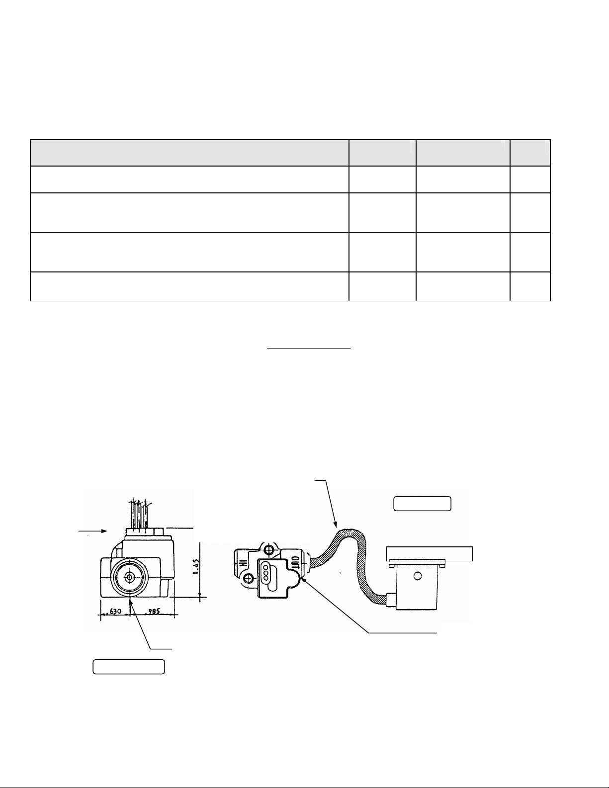
The transducer output port should be mounted lower or even with the carburetor inlet port (or fuel servo on a fuel injected
engine). If this is not possible, a loop should be put in the fuel line between the Fuel Flow Transducer and the carburetor or fuel
servo (see diagram below).
Do not remove the caps on the flow transducer until the fuel hoses are ready to be installed.
The flow of fuel through the transducer must follow the direction marked on the transducer.
Mount the
transducer
with the
wires up.
If the transducer is higher
than the carburetor or fuel
servo, put a loop in the fuel
line between the transducer
and the carburetor or fuel
Carburetor or Servo
Location
Between Fuel tank and
Carburetor.
Between throttle body
and fuel flow divider.
Between engine driven
pump and servo/throttle
body or carburetor
One transducer in Carb
inlet line and one
transducer in out let line
SIDE VIEW
Page
8
9
10
8, 11,
12
The direction of the fuel
¼ NPT
END VIEW UP
flow through the transducer
is marked on top

J.P.Instruments
Fuel Flow Installation Manual
Report # 503
for EGT-701 with Fuel Flow Option Page 5 of 14
Rev B : Date 03/14/97
The flow transducer must be mounted so the wires exiting the transducer are pointing up.
Before connecting any hoses, thoroughly clean them and insure they are free of any loose material. High air pressure my
be used, However, do not allow high air pressure to pass through the flow transducer.
4…. Route the (Optional) External Warning Control Line:
The wire from pin 12 on the J-1 (D-SUB 25) Connector can be connected to an external warning light or buzzer.
This wire grounds when the display flashing a warning is on. The current in this line must be limited to 2/10 of an amp
maximum. Exceeding this limit will damage the unit. If this feature is not used leave this line open. Tie wrap this wire so
it does not obstruct the freedom of travel- controls.
5…. Install the Instrument in the Panel:
Manual, STC 2586NM)
Locate a 2.25 diameter hole in the instrument panel, where you would like to mount the indicator per drawing 700124. A
steel template supplied with the installation kit is used as a guide for drilling two button holes in the instrument panel. Align
and Mount the Template into the instrument panel hole. First drilling a 0.125 hole. Remove the template and check the
instrument alignment, if OK redrill with a 0.147 drill. The EGT-701(),with Fuel Flow option mounts in a standard 2.25"
instrument hole. The instrument configures itself automatically for 4 to 9 cylinder, 14/28 volt aircraft. The instrument is
7.5” deep less connectors and is 2.6 square behind the panel. To prevent display damage it is essential that the mounting
screws not penetrate the bezel more than .12 inches.
The indicator is FAA TSO approved, as a temperature indicator under TSO-C43b and must be installed in
accordance with STC SA2586NM.
(The following section is an excerpt from report #103 Installation
Mount the placard "Do Not Rely on Fuel Flow Instrument to Determine Fuel Levels in Tanks" on the aircraft
instrument panel near the EGT-701(), with fuel flow option. If the aircraft is equipped with a primary fuel flow
instrument, the following placard must be mounted on the aircraft instrument panel near the EGT-701(),with Fuel Flow
option: "Refer to Original Fuel Flow Instrumentation for Primary Information".
6…. Route the Fuel Flow Transducer Wires:
Manual, STC 2586NM)
(The following section is an excerpt from report #103 Installation
Route the thermocouple and fuel flow wires from the probes through the firewall using fireproof rubber grommets and
flame retarding silicone. Use an existing hole if possible. Following the existing wiring harness and connect to the
indicator marking each lead with the cylinder number. All wires must be routed away from high temperature areas
(exhaust stacks, turbochargers, etc.). Secure Probe leads to a convenient location on the engine approximately 8 to 12
inches from the probe, being sure there is sufficient slack to absorb engine torque. It is essential in routing the probe and
fuel flow transducer wires not be allowed to touch metal parts of the air-frame or engine since abrasion will destroy this
wire. Connect wires in accordance with dwg 700744, page 12
7….. System Checkout:
Check instrument operation as follows:
1. Turn the aircraft master switch on (engine off) and set the toggle switch to Fuel Flow . Tap the step switch until 0
GPH is displayed. Turn the boost pump on for a few seconds. The display should indicate 3 to 8 GPH.. A problem at
this step could be caused by poor connections on the red or black power and ground leads.
2. Set the instrument toggle switch to "Fuel Flow" and check for a digital fuel flow reading of "00 GPH" indicates the
fuel flow is too low to register. A reading of “ ---GPH “ dashes indicate no fuel flow transducer signals. A problem
at this step could be caused by a poor connection or crossed flow transducer wires.
3. With the engine running, check the "FLOW" Display Mode to read properly. If there is a problem at this point
to EDM-700 Fuel Flow Option Supplement Rev C. Section 4
for troubleshooting information.
Refer
4. After running the engine, check the fuel hoses, transducers and fittings for leaks.
 Loading...