

Page 1

Export: 29.04.2016 Copyright by Joy-IT - Published under CC BY-NC-SA 3.0
Page 2

Dear customer,
Export: 16.06.2017 Copyright by Joy-IT - Published under CC BY-NC-SA 3.0 Page 2 of 214
thank you for purchasing our product.
This high quality sensor kit was developed especially for the popular Open-Source platforms.
It is compatible to the following single-board computers:
Raspberry Pi (all models), Arduino, Banana PI, Cubieboard, Cubietruck, Beaglebone, pcDuino and
many more microcontroller-systems (Atmega, MicroChip PIC, STM32 etc.).
The following instruction not only contains the technical description to every sensor, like the PINassignment or the used chipset, but also shows an insight to the functionality of the sensor
modules.
To assist you at your own projects, we put a code example, for the most used systems, Raspberry
Pi (written in Python) and Arduino (written in C++), to every sensor description. You can find the
code directly in this manual or you can download it right beneath the examples. You can also
download the most current version of our examples at our SensorKit X40 Wiki:
http://sensorkit.en.joy-it.net/
With our examples, even beginners can easily make their own experiments and projects.
So you have in less than no time the possibility to measure your own heart rate or to check the
temperature or humidity of your environment.
Especially for the Raspberry Pi, we put our Analog-Digital converter (KY-053) and our voltage
translator to our kit. With these two modules, two of the biggest disadvantages, when it comes
to interaction, of the Raspberry Pi (no ADC, 3.3V voltage-level) are resolved.
You can either directly solder the sensors or put them on a breadboard to work on different
experiments.
We wish you a lot of joy with your Sensorkit X40.
Your Joy-IT Team
Page 3
Main Page
Main Page
Click the picture or the description to go to the site of the specific sensor.
Temperature sensor moduleKY-001
Vibration-switch moduleKY-002
Hall Magneticfield-Sensor moduleKY-003
Export: 16.06.2017 Copyright by Joy-IT - Published under CC BY-NC-SA 3.0 Page 3 of 214
Page 4
Main Page
Button-moduleKY-004
Infrared Transmitter moduleKY-005
Passiv Piezo-Buzzer moduleKY-006
RGB LED SMD moduleKY-009
Light barrier-moduleKY-010
Export: 16.06.2017 Copyright by Joy-IT - Published under CC BY-NC-SA 3.0 Page 4 of 214
Page 5
Main Page
2-Color (Red+Green) 5mm LED moduleKY-011
Active Piezo-Buzzer moduleKY-012
Temperature-Sensor moduleKY-013
Combi-Sensor Temperature+HumidityKY-015
RGB 5mm LED moduleKY-016
Export: 16.06.2017 Copyright by Joy-IT - Published under CC BY-NC-SA 3.0 Page 5 of 214
Page 6
Main Page
Tilt switch moduleKY-017
Photoresistor moduleKY-018
5V Relais moduleKY-019
Tilt switch moduleKY-020
Mini magnetic Reed moduleKY-021
Infrared receiver moduleKY-022
Export: 16.06.2017 Copyright by Joy-IT - Published under CC BY-NC-SA 3.0 Page 6 of 214
Page 7
Main Page
Joystick module (XY-Axis)KY-023
Linear magnetic Hall sensorKY-024
Reed moduleKY-025
Flame-sensor moduleKY-026
Magic light cup moduleKY-027
Export: 16.06.2017 Copyright by Joy-IT - Published under CC BY-NC-SA 3.0 Page 7 of 214
Page 8
Main Page
Temperature Sensor module (Thermistor)KY-028
2-Color (Red+Green) 3mm LED moduleKY-029
Knock-sensor moduleKY-031
Obstacle-detect moduleKY-032
Tracking sensor moduleKY-033
Export: 16.06.2017 Copyright by Joy-IT - Published under CC BY-NC-SA 3.0 Page 8 of 214
Page 9
Main Page
7 Colour LED flash-moduleKY-034
Bihor magnetic sensor moduleKY-035
Metal-touch sensor moduleKY-036
Microphone sensor module (high sensitivity)KY-037
Microphone sound sensor moduleKY-038
Heartbeat sensor moduleKY-039
Export: 16.06.2017 Copyright by Joy-IT - Published under CC BY-NC-SA 3.0 Page 9 of 214
Page 10
Main Page
Rotary encoderKY-040
Ultrasonic-distance-sensorKY-050
Voltage translator / Level shifterKY-051
KY-052 Pressure-sensor / Temperature-sensor (BMP280)
Analog digital converterKY-053
Export: 16.06.2017 Copyright by Joy-IT - Published under CC BY-NC-SA 3.0 Page 10 of 214
Page 11
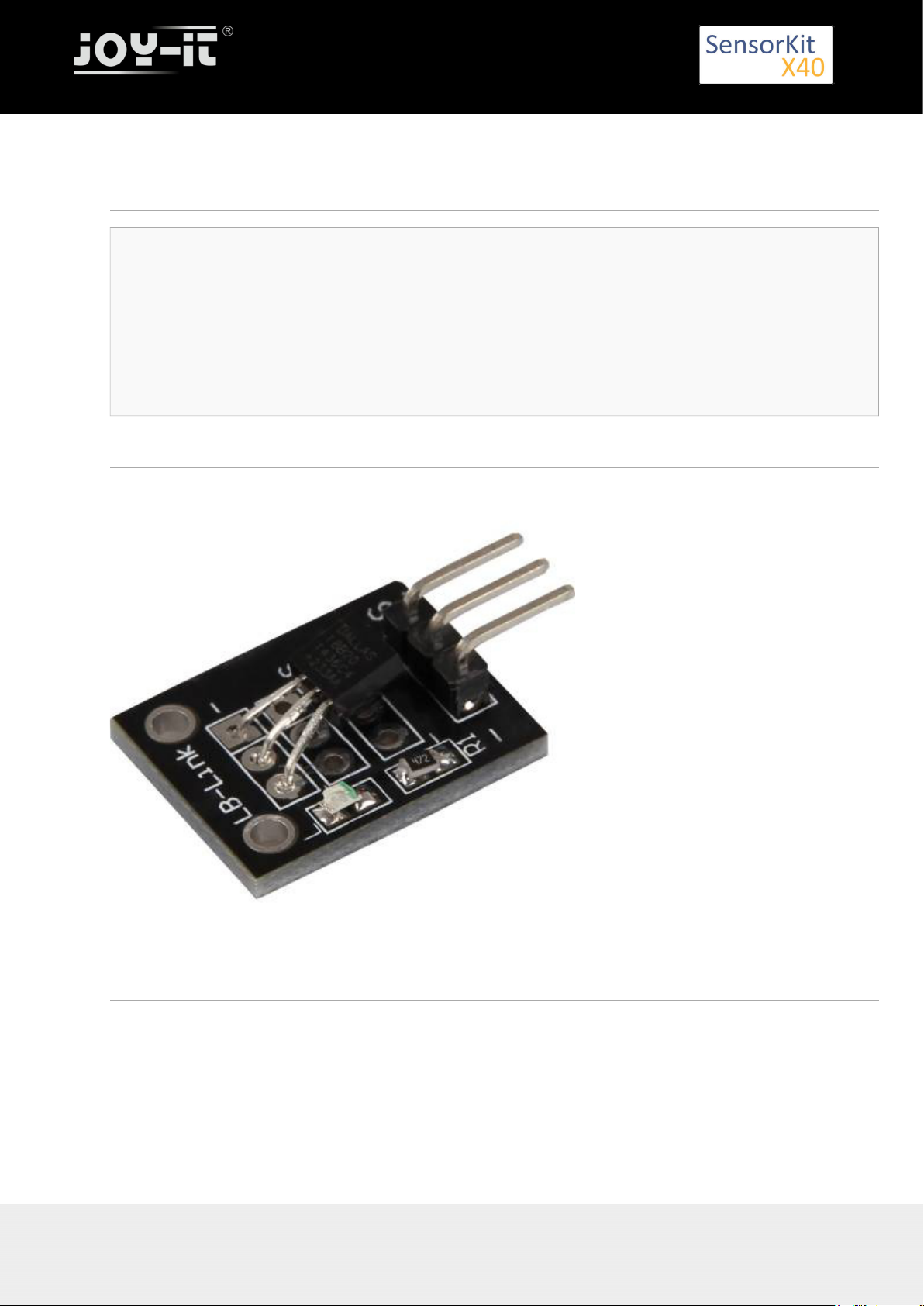
KY-001 Temperature sensor module
KY-001 Temperature sensor module
Contents
1 Picture ................................................................................................................................................................. 1
2 Technical Data / Short description ....................................................................................................................... 1
3 Pinout ................................................................................................................................................................... 2
4 Code example Arduino ......................................................................................................................................... 2
5 One-Wire configuration for Raspberry Pi ............................................................................................................. 3
6 Code example Raspberry Pi ................................................................................................................................. 3
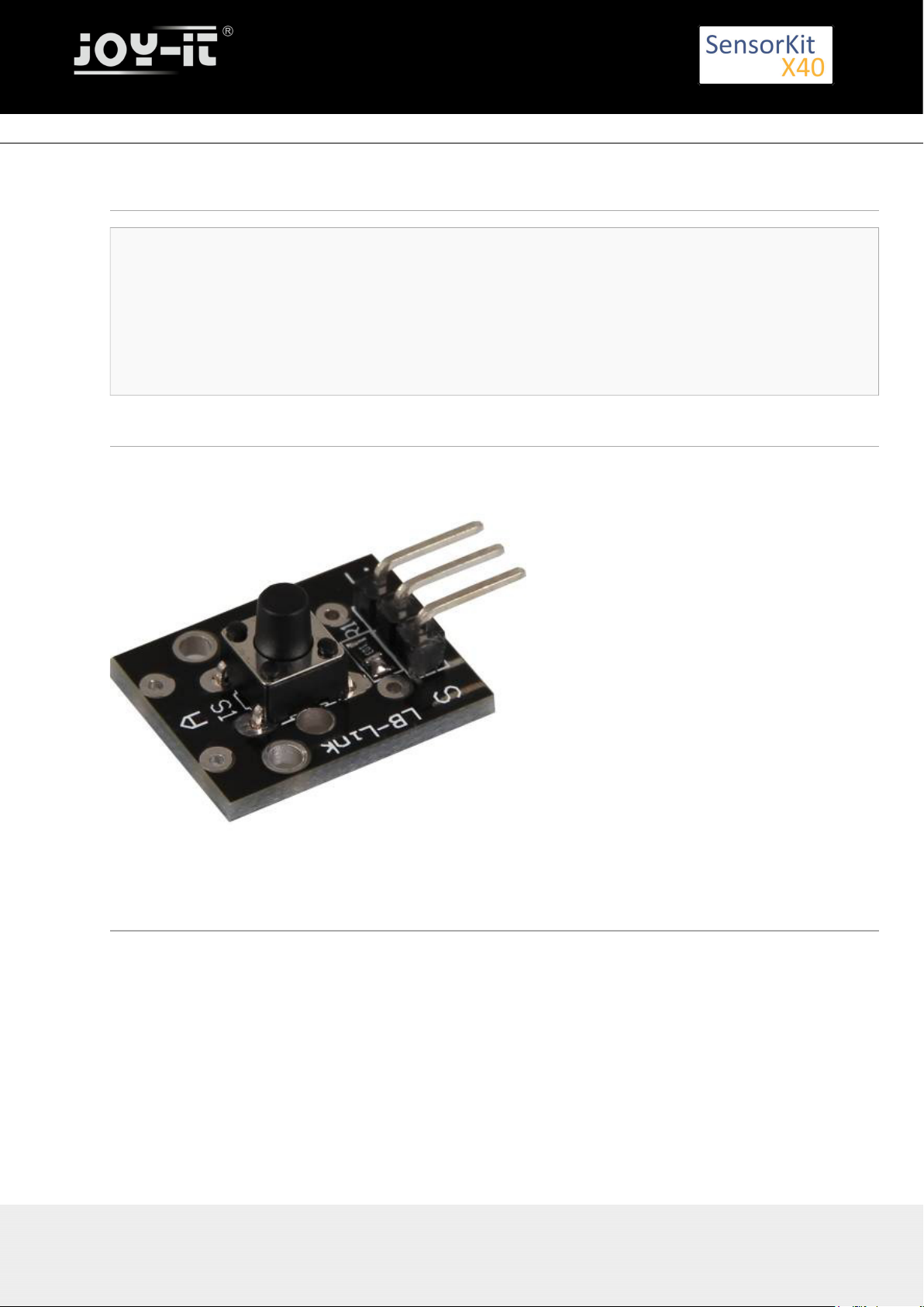
Picture
Technical Data / Short description
Chip: DS18B20 | Communication protocol: 1-Wire
9- 12Bit precise temperature measurment between –55°C and +125°C
Export: 16.06.2017 Copyright by Joy-IT - Published under CC BY-NC-SA 3.0 Page 11 of 214
Page 12
Pinout
Code example Arduino
You need 2 additional libraries for the following example:
- [OneWire Library] from | published under the MIT license.Paul Stoffregen
- [Dallas Temperature Control Library] from | published under LGPLMiles Burton
Both libraries are part of the package and needs to be copied into the "Library" folder before starting the
Arduino IDE.
You can find the path at C:\user\[username]\documents\Arduino\libraries by default.
// import needed libraries
#include <DallasTemperature.h>
#include <OneWire.h>
// Declaration of the input pin which is connected with the sensor module
#define KY001_Signal_PIN 4
// libraries configuration
OneWire oneWire(KY001_Signal_PIN);
DallasTemperature sensors(&oneWire);
void setup() {
// serial output initialization
Serial.begin(9600);
Serial.println("KY-001 temperature measurement");
// sensor will be initialized
sensors.begin();
}
//main program loop
Export: 16.06.2017 Copyright by Joy-IT - Published under CC BY-NC-SA 3.0 Page 12 of 214
KY-001 Temperature sensor module
Page 13

KY-001 Temperature sensor module
void loop()
{
// temperature measurment will be started...
sensors.requestTemperatures();
// ... and measured temperature will be displayed
Serial.print("Temperature: ");
Serial.print(sensors.getTempCByIndex(0));
Serial.write(176); // UniCode of the char-symbol "°-Symbol"
Serial.println("C");
delay(1000); // 1s break till next measurment
}
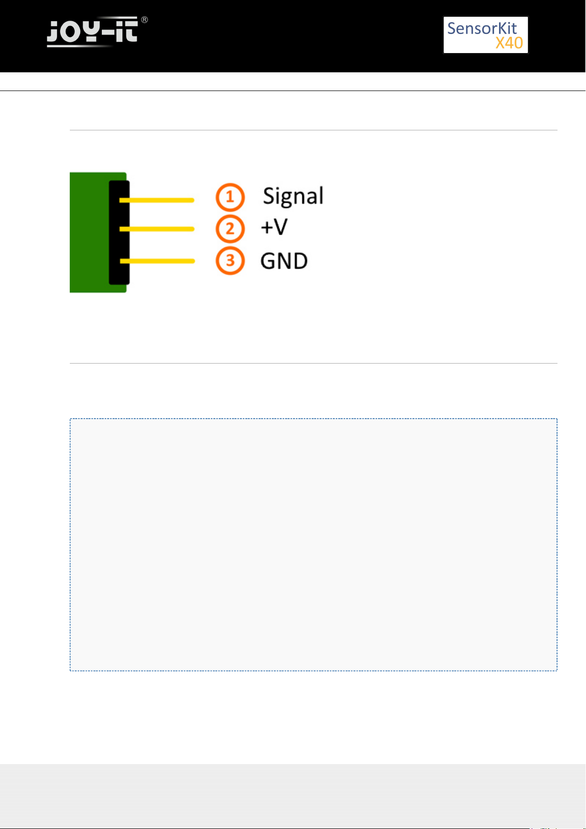
Connections Arduino:
Sensor Signal = [Pin 4]
Sensor+V = [Pin 5V]
Sensor - = [Pin GND]
Example program download
KY-001-TemperatureSensor
One-Wire configuration for Raspberry Pi
To activate the communication between the Raspberry Pi and the DS18B20 sensor, an additional
configuration needs to be made.
You need to modify the „/boot/contig.txt“ file and add the following line to it:
dtoverlay=w1-gpio,gpiopin=4
You can modify the file by entering the following command to the console:
sudo nano /boot/config.txt
You can safe the modification by pressing [CTRL+Y] and leave the editor by pressing [CTRL+X].
At last, you need to reboot your Raspberry Pi with the following command.
If you followed these steps, your system is ready for the example below.
sudo reboot
Code example Raspberry Pi
# coding=utf-8
# needed modules will be imported and initialised
import glob
import time
from time import sleep
import RPi.GPIO as GPIO
Export: 16.06.2017 Copyright by Joy-IT - Published under CC BY-NC-SA 3.0 Page 13 of 214
Page 14

KY-001 Temperature sensor module
Export: 16.06.2017 Copyright by Joy-IT - Published under CC BY-NC-SA 3.0 Page 14 of 214
# here you can modify the break between the measurements
sleeptime = 1
# the one-wire input pin will be declared and the integrated pullup-resistor will be enabled
GPIO.setmode(GPIO.BCM)
GPIO.setup(4, GPIO.IN, pull_up_down=GPIO.PUD_UP)
# After the enabling of the resistor you have to wait till the communication has started
print 'wait for initialisation...'
base_dir = '/sys/bus/w1/devices/'
while True:
try:
device_folder = glob.glob(base_dir + '28*')[0]
break
except IndexError:
sleep(0.5)
continue
device_file = device_folder + '/w1_slave'
# The function to read currently measurement at the sensor will be defined.
def TemperaturMessung():
f = open(device_file, 'r')
lines = f.readlines()
f.close()
return lines
# To initialise, the sensor will be read "blind"
TemperaturMessung()
# Analysis of temperature: At the Raspberry Pi
# noticed one-wire slaves at the directory /sys/bus/w1/devices/
# will be assigned to a own subfolder.
# In this folder is the file in which the data from the one-wire bus will be saved
def TemperaturAuswertung():
lines = TemperaturMessung()
while lines[0].strip()[-3:] != 'YES':
time.sleep(0.2)
lines = TemperaturMessung()
equals_pos = lines[1].find('t=')
if equals_pos != -1:
temp_string = lines[1][equals_pos+2:]
temp_c = float(temp_string) / 1000.0
return temp_c
# main program loop
# The measured temperature will be displayed via console, between the measurements is a break.
# The break time can be configured by the variable "sleeptime"
try:
while True:
print '---------------------------------------'
print "Temperature:", TemperaturAuswertung(), "°C"
time.sleep(sleeptime)
except KeyboardInterrupt:
GPIO.cleanup()
Connections Raspberry Pi:
Signal = GPIO4 [Pin 7]
+V = 3,3V [Pin 1]
GND = GND [Pin 6]
Example program download:
Page 15

KY-001 Temperature sensor module
KY-001_RPi_TemperatureSensor.zip
To start the program use the command:
sudo python KY-001_RPi_TemperaturSensor.py
Export: 16.06.2017 Copyright by Joy-IT - Published under CC BY-NC-SA 3.0 Page 15 of 214
Page 16
KY-002 Vibration-switch module
KY-002 Vibration-switch module
Contents
1 Picture ................................................................................................................................................................. 1
2 Technical Data / Short discription ........................................................................................................................ 1
3 Pinout ................................................................................................................................................................... 2
4 Code example Arduino ......................................................................................................................................... 2
5 Code example for Raspberry Pi ........................................................................................................................... 3
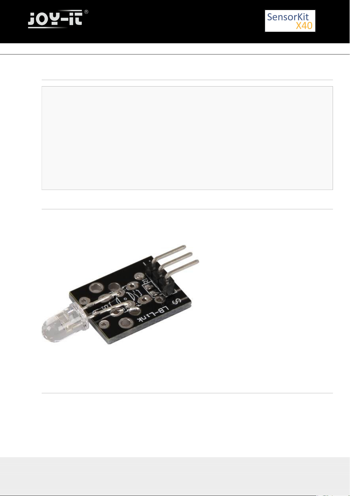
Picture
Technical Data / Short discription
On vibration, the contact of the two input pins will beconnected.
Export: 16.06.2017 Copyright by Joy-IT - Published under CC BY-NC-SA 3.0 Page 16 of 214
Page 17

Pinout
Code example Arduino
This example will activate a LED as soon as the sensor detects a signal.
The modules KY-011, KY-016 or KY-029 can be used as a LED.
int Led = 13 ;// Declaration of the LED output pin
int Sensor = 10; // Declaration of the Sensor input pin
int val; // Temporary variable
void setup ()
{
pinMode (Led, OUTPUT) ; // Initialisation output pin
pinMode (Sensor, INPUT) ; // Initializstion sensor pin
digitalWrite(Sensor, HIGH); // Activating of the internal pull-up resistors
}
void loop ()
{
val = digitalRead (Sensor) ; // The active signal at the sensor will be read
if (val == HIGH) // If a signal was noticed, the LED will be on
{
digitalWrite (Led, LOW);
}
else
{
digitalWrite (Led, HIGH);
}
}
Connections Arduino:
LED + = [Pin 13]
LED - = [Pin GND]
Sensor Signal = [Pin 10]
Export: 16.06.2017 Copyright by Joy-IT - Published under CC BY-NC-SA 3.0 Page 17 of 214
KY-002 Vibration-switch module
Page 18

KY-002 Vibration-switch module
To start use the following command line:
sudo python SensorTest_RPi.py
Export: 16.06.2017 Copyright by Joy-IT - Published under CC BY-NC-SA 3.0 Page 18 of 214
Sensor+V = [Pin 5V]
Sensor - = [Pin GND]
Example program download
SensorTest_Arduino
Code example for Raspberry Pi
# needed modules will be imported
import RPi.GPIO as GPIO
import time
GPIO.setmode(GPIO.BCM)
# The input pin of the Sensor will be declared. The pullup resistor will be activated.
GPIO_PIN = 24
GPIO.setup(GPIO_PIN, GPIO.IN, pull_up_down = GPIO.PUD_UP)
print "Sensor-Test [press ctrl+c to end it]"
# This output function will be started at signal detection
def outFunction(null):
print("Signal detected")
# At the moment of detecting a Signal ( falling signal edge ) the output function will be activated.
GPIO.add_event_detect(GPIO_PIN, GPIO.FALLING, callback=outFunction, bouncetime=100)
# main program loop
try:
while True:
time.sleep(1)
# Scavenging work after the end of the program
except KeyboardInterrupt:
GPIO.cleanup()
Connections Raspberry Pi:
Signal = GPIO24 [Pin 18]
+V = 3,3V [Pin 1]
GND = GND [Pin 6]
Example program download SensorTest_RPi
Page 19
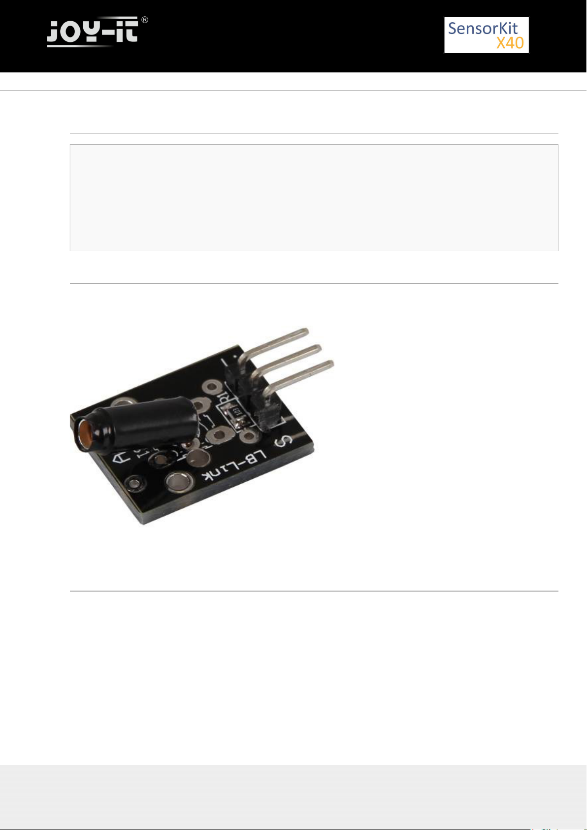
KY-003 Hall Magneticfield-Sensor module
KY-003 Hall Magneticfield-Sensor module
Contents
1 Picture ................................................................................................................................................................. 1
2 Technical Data / Short description ....................................................................................................................... 1
3 Pinout ................................................................................................................................................................... 2
4 Code example Arduino ......................................................................................................................................... 2
5 Code example for Raspberry Pi ........................................................................................................................... 3
Picture
Technical Data / Short description
Chipset: A3141
Sensor type: Hall Effect Transistor/Switch
If the sensor is near a magnetic field, the transistor will switch the circuit.
The result is an analog voltage at the signal output.
Export: 16.06.2017 Copyright by Joy-IT - Published under CC BY-NC-SA 3.0 Page 19 of 214
Page 20
Pinout
Code example Arduino
This example will light up a LED as soon as the sensor is near a magnetic field.
The module KY-011, KY-016 or KY-029 can be used as a LED.
int Led = 13 ;// Declaration of the LED-output pin
int Sensor = 10; // Declaration of the sensor input pin
int val; // Temporary variable
void setup ()
{
pinMode (Led, OUTPUT) ; // Initialization output pin
pinMode (Sensor, INPUT) ; // Initialization sensor pin
digitalWrite(Sensor, HIGH); // Activating internal pull-up resistor
}
void loop ()
{
val = digitalRead (Sensor) ; // The current signal at the sensor will be read.
if (val == HIGH) // If a signal was detected, the LED will light up.
{
digitalWrite (Led, LOW);
}
else
{
digitalWrite (Led, HIGH);
}
}
Connections Arduino:
LED + = [Pin 13]
LED - = [Pin GND]
Sensor Signal = [Pin 10]
Export: 16.06.2017 Copyright by Joy-IT - Published under CC BY-NC-SA 3.0 Page 20 of 214
KY-003 Hall Magneticfield-Sensor module
Page 21

KY-003 Hall Magneticfield-Sensor module
Export: 16.06.2017 Copyright by Joy-IT - Published under CC BY-NC-SA 3.0 Page 21 of 214
Sensor+V = [Pin 5V]
Sensor - = [Pin GND]
Example program download:
SensorTest_Arduino
Code example for Raspberry Pi
# needed modules will be imported
import RPi.GPIO as GPIO
import time
GPIO.setmode(GPIO.BCM)
# The input pin of the sensor will be declared. The pull-up resistor will be activated.
GPIO_PIN = 24
GPIO.setup(GPIO_PIN, GPIO.IN, pull_up_down = GPIO.PUD_UP)
print "Sensor-Test [press ctrl+c to end it]"
# This output function will be started at signal detection
def ausgabeFunktion(null):
print("Signal detected")
# At the moment of detecting a signal the output function will be activated.
GPIO.add_event_detect(GPIO_PIN, GPIO.FALLING, callback=ausgabeFunktion, bouncetime=100)
# main program loop
try:
while True:
time.sleep(1)
# Scavenging work after the end of the program
except KeyboardInterrupt:
GPIO.cleanup()
Connections Raspberry Pi:
Signal = GPIO24 [Pin 18]
+V = 3,3V [Pin 1]
GND = GND [Pin 6]
Example program download:
SensorTest_RPi
To start use the following command line:
sudo python SensorTest_RPi.py
Page 22
KY-004 Button-module
KY-004 Button-module
Contents
1 Picture ................................................................................................................................................................. 1
2 Technical data / Short description ....................................................................................................................... 1
3 Pinout ................................................................................................................................................................... 2
4 Code example Arduino ......................................................................................................................................... 2
5 Code example Raspberry Pi ................................................................................................................................. 3
Picture
Technical data / Short description
By pressing the button, the signal circuit is switched.
Export: 16.06.2017 Copyright by Joy-IT - Published under CC BY-NC-SA 3.0 Page 22 of 214
Page 23

Pinout
Code example Arduino
This example will light up a LED after the button is pressed.
The module KY-011, KY-016 or KY-029 can be used as a LED.
int Led = 13 ;// Declaration of the LED-output pin
int Sensor = 10; // Declaration of the sensor input pin
int val; // Temporary variable
void setup ()
{
pinMode (Led, OUTPUT) ; // Initialization output pin
pinMode (Sensor, INPUT) ; // Initialization sensor pin
digitalWrite(Sensor, HIGH); // Activating internal pull-up resistor
}
void loop ()
{
val = digitalRead (Sensor) ; // The current signal at the sensor will be read
if (val == HIGH) // If a signal was detected, the LED will light up.
{
digitalWrite (Led, LOW);
}
else
{
digitalWrite (Led, HIGH);
}
}
Connections Arduino:
LED + = [Pin 13]
LED - = [Pin GND]
Sensor Signal = [Pin 10]
Export: 16.06.2017 Copyright by Joy-IT - Published under CC BY-NC-SA 3.0 Page 23 of 214
KY-004 Button-module
Page 24

KY-004 Button-module
Export: 16.06.2017 Copyright by Joy-IT - Published under CC BY-NC-SA 3.0 Page 24 of 214
Sensor+V = [Pin 5V]
Sensor - = [Pin GND]
Example program download:
SensorTest_Arduino
Code example Raspberry Pi
# needed modules will be imported
import RPi.GPIO as GPIO
import time
GPIO.setmode(GPIO.BCM)
# The input pin of the Sensor will be declared. The pull-up resistor will be activated.
GPIO_PIN = 24
GPIO.setup(GPIO_PIN, GPIO.IN, pull_up_down = GPIO.PUD_UP)
print "Sensor-Test [press ctrl+c to end it]"
# This output function will be started at signal detection.
def ausgabeFunktion(null):
print("Signal detected")
# At the moment of detecting a Signal the output function will be activated.
GPIO.add_event_detect(GPIO_PIN, GPIO.FALLING, callback=ausgabeFunktion, bouncetime=100)
# main program loop
try:
while True:
time.sleep(1)
# Scavenging work after the end of the program
except KeyboardInterrupt:
GPIO.cleanup()
Connections Raspberry Pi:
Signal = GPIO24 [Pin 18]
+V = 3,3V [Pin 1]
GND = GND [Pin 6]
Example program download
SensorTest_RPi
To start, enter the following command:
sudo python SensorTest_RPi.py
Page 25
KY-005 Infrared Transmitter module
KY-005 Infrared Transmitter module
Contents
1 Picture ................................................................................................................................................................. 1
2 Technical data / Short description ....................................................................................................................... 1
3 Pinout ................................................................................................................................................................... 2
4 Code example Arduino ......................................................................................................................................... 2
5 Code example Raspberry Pi ................................................................................................................................. 4
5.1 Code example remote ................................................................................................................................ 4
5.2 Lirc Installation ........................................................................................................................................... 5
5.3 IR-Receiver Test ......................................................................................................................................... 6
5.4 Remote teach ............................................................................................................................................. 7
5.5 Sending a command via Infrared Transmitter ............................................................................................ 8
Picture
Technical data / Short description
A LED which emits infrared light. A resistor might be necessary for some voltages.
Vf= 1,1V
If= 20mA
Export: 16.06.2017 Copyright by Joy-IT - Published under CC BY-NC-SA 3.0 Page 25 of 214
Page 26
KY-005 Infrared Transmitter module
emitted wavelength: 940nm
(not visible for the human eye)
Pre-resistor:
Rf (3,3V) = 120Ω
[used with ARM CPU-Core based microcontroller]
Rf (5V) = 220Ω
[used with Atmel Atmega based microcontroller]
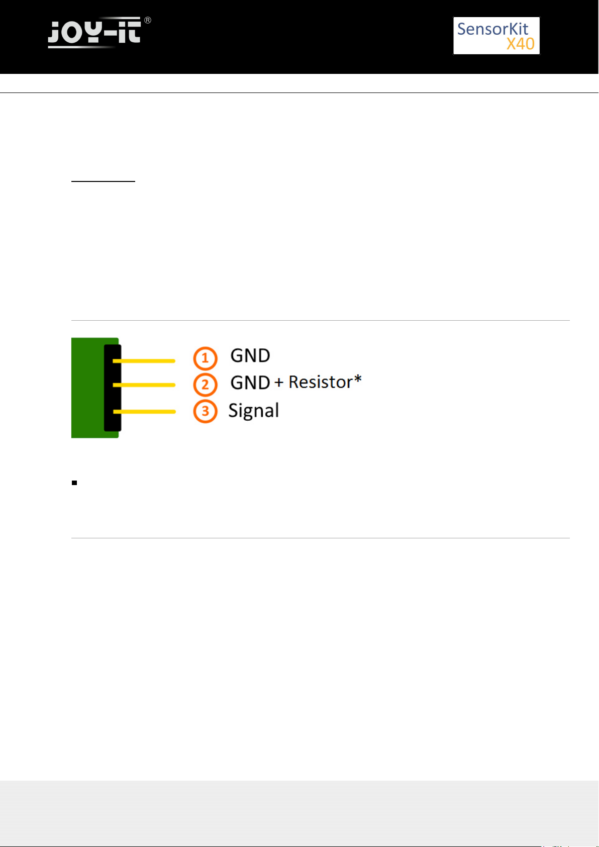
Pinout
You can directly solder a resistor to the circuit board. In that case, the central pin (2), which includes the
resistor, can be used.
Code example Arduino
With both sensor modules, KY-005 and KY-022, you can build an infrared remote + infrared receiver system.
In order to do this, you will need the two sensor modules as well as two Arduinos.
The first one will handle the receiver system and the second one will handle the transmitter system.
An additional library is needed for this code example:
-[Arduino-IRremote] from | published under LGPL
Ken Shirriff
The library is in the package and has to be copied before the start into the library folder.
You can find your Arduino Library folder at: C:\User\[UserName]\Documents\Arduino\libraries
There are different infrared protocolls to send data. In this example we use the RC5 protocol.
The used library "Arduino-IRremote" converts the data independently.
The library has additional protocolls, they are marked in this documentation.
Export: 16.06.2017 Copyright by Joy-IT - Published under CC BY-NC-SA 3.0 Page 26 of 214
Page 27

KY-005 Infrared Transmitter module
Export: 16.06.2017 Copyright by Joy-IT - Published under CC BY-NC-SA 3.0 Page 27 of 214
Code for the receiver:
// Arduino-IRremote library will be added
#include <IRremote.h>
#include <IRremoteInt.h>
// You can declare the input pin for the signal output of the KY-022 here
int RECV_PIN = 11;
// Arduino-IRremote library will be initialized
IRrecv irrecv(RECV_PIN);
decode_results results;
void setup()
{
Serial.begin(9600);
irrecv.enableIRIn(); // Infrared receiver will start
}
// main program loop
void loop() {
// It will be checked if the receiver has gotten a signal.
if (irrecv.decode(&results)) {
//At signal input, the received and decoded signal will show via serial console.
Serial.println(results.value, HEX);
irrecv.resume();
}
}
Code for the transmitter:
//Arduino-IRremote library will be added
#include <IRremote.h>
#include <IRremoteInt.h>
//...and here initialized
IRsend irsend;
// The configuration of the output pin will be made by the library
// The output pin is a different one for different arduinos
// Arduino UNO: Output = D3
// Arduino MEGA: Output = D9
// You will find a full list of output pins on the website:
// http://z3t0.github.io/Arduino-IRremote/
void setup()
{
}
// main program loop
void loop() {
// The transmitter sends the signal A90 (hex. dezimal form) in the encoding "RC5"
// It will be transmitted 3 times after that it will make a 5 second break
for (int i = 0; i < 3; i++) {
irsend.sendRC5(0xA90, 12); //[12] Bit-length signal (hex A90=1010 1001 0000)
delay(40);
}
delay(5000); // 5 second break between the sending impulses
}
Example program download:
Page 28

KY-005 Infrared Transmitter module
KY-005_KY-022_Infrared-Modules_ARD
Connections Arduino 1 [Receiver]:
KY-022
Signal = [Pin 11]
+V = [Pin 5V]
GND = [Pin GND]
Connections Arduino 2 [Transmitter]:
KY-005
Signal = [Pin 3 (Arduino Uno) | Pin 9 (Arduino Mega)]
GND+resistor = [Pin GND*]
GND = [Pin GND]
* Only if resistor was soldered to the circuit board.
Code example Raspberry Pi
Code example remote
Because of its progressive processor architecture, the Raspberry Pi has a big advantage, compared to the
Arduino.
It can run a full Linux OS.
With help of an infrared-receiver, it is not only able to transmit simple data signals, furthermore it can
control complete programs via remote.
To setup an infrared control system, we recommend to use the Linux software "lirc" (published under the
LGPL- ).Website
In the following section, we show you how to use lirc and how the remotely send the learned signals via
infrared.
On this purpose, the module KY-005 will be used as an infrared-transmitter and the KY-022 will be used as
an infrared-receiver.
Connections Raspberry Pi:
KY-005
Signal = GPIO17 [Pin 11]
GND+resistor = GND* [Pin 9]
GND = GND [Pin 6]
* Only if a resistor was soldered to the module
Export: 16.06.2017 Copyright by Joy-IT - Published under CC BY-NC-SA 3.0 Page 28 of 214
Page 29

KY-005 Infrared Transmitter module
KY-022
Signal = GPI18 [Pin 12]
+V = 3,3V [Pin 17]
GND = GND [Pin 25]
Lirc Installation
Open a terminal at the desktop or use SSH to log into your Raspberry Pi. To install lirc, enter the following
command:
sudo apt-get install lirc -y
[For this the Raspberry Pi has to be connected to the internet]
To use the lirc module immediately after starting the OS, you have to add the following line to the end of the
file "/boot/config.txt":
dtoverlay=lirc-rpi,gpio_in_pin=18,gpio_out_pin=17,gpio_in_pull=up
The "gpio_in_pin=18" will be defined as an input pin of the IR-receiver and the "gpio_out_pin=17" as an
output pin of the IR-transmitter.
The file can be edited by entering the command:
sudo nano /boot/config.txt
You can save and close the file via the key sequence [ctrl+x -> y -> enter]
You will also have to modify the file "/etc/lirc/hardware.conf" by entering the command:
sudo nano /etc/lirc/hardware.conf
In this file you have to change following lines:
DRIVER="UNCONFIGURED"
--->>
DRIVER="default"
DEVICE=""
--->>
DEVICE="/dev/lirc0"
MODULES=""
--->>
MODULES="lirc_rpi"
The modified file should now look like:
Export: 16.06.2017 Copyright by Joy-IT - Published under CC BY-NC-SA 3.0 Page 29 of 214
Page 30

KY-005 Infrared Transmitter module
# /etc/lirc/hardware.conf
#
# Arguments which will be used when launching lircd
LIRCD_ARGS=""
#Don't start lircmd even if there seems to be a good config file
#START_LIRCMD=false
#Don't start irexec, even if a good config file seems to exist.
#START_IREXEC=false
#Try to load appropriate kernel modules
LOAD_MODULES=true
# Run "lircd --driver=help" for a list of supported drivers.
DRIVER="default"
# usually /dev/lirc0 is the correct setting for systems using udev
DEVICE="/dev/lirc0"
MODULES="lirc_rpi"
# Default configuration files for your hardware if any
LIRCD_CONF=""
LIRCMD_CONF=""
After that we reboot the Raspberry Pi with the following command:
sudo reboot
IR-Receiver Test
To test the connected receiver, you have to close lirc first with the following command:
sudo /etc/init.d/lirc stop
After that, you can test if signals could be detected on the Raspberry Pi by using the following command:
mode2 -d /dev/lirc0
and by pressing random keys on an infrared remote. You should see numbers in the following form:
space 95253
pulse 9022
space 2210
pulse 604
space 95246
pulse 9019
space 2211
pulse 601
space 95252
pulse 9019
space 2210
Export: 16.06.2017 Copyright by Joy-IT - Published under CC BY-NC-SA 3.0 Page 30 of 214
Page 31

KY-005 Infrared Transmitter module
pulse 603
space 95239
pulse 9020
space 2208
pulse 603
...
You can restart lirc with the following command:
sudo /etc/init.d/lirc start
Remote teach
To register an infrared-remote at the lirc system, you have to configure the file "/etc/lirc"lircd.conf".
In this file, all command assignments of the infrared codes are saved.
To get a good formatted lircd.conf, use the lirc assistant software which creates the file automatically.
To start this process you have to stop lirc first by using the command:
sudo /etc/init.d/lirc stop
With the following command, we can start the assistant:
irrecord -d /dev/lirc0 ~/MeineFernbedienung.conf
The assistant will start an initialization of the remote, in this initialization you have to press a few keys so
that the lirc system is able to learn the encoding of the remote. For that, please follow the instructions of the
assistant. After the initialization, the assistant asks for the name of the key which should get a new infrared
code. You can choose your key from the following file:
FernbedienungsCodes.txt
You have to type these into the assistant and need to confirm with enter. After this, the recording of the
infrared code for the chosen key will start.
Example: type in [KEY_0] - - -> confirm with enter - - -> press key 0 of the remote - - -> waiting for the
assistant to confirm the recording.
If no more keys need to be configured, you can close the assistant by pressing the enter key. After this, the
configuration file is created, but you have to choose a name for the recorded remote. For this we have to
open the file with the editor:
Export: 16.06.2017 Copyright by Joy-IT - Published under CC BY-NC-SA 3.0 Page 31 of 214
Page 32

KY-005 Infrared Transmitter module
sudo nano ~/MeineFernbedienung.conf
Here you have to change the line:
name /home/pi/MeineFernbedienung.conf
to
name MeineFernbedienung
Please don't use any spaces or additional characters in the name.
You can save and close the file with the key sequence [ctrl+x ---> y ---> enter].
After creating the configuration, you can make a backup for original lircd.conf with the following command:
sudo mv /etc/lirc/lircd.conf /etc/lirc/lircd.conf.bak
With the command
sudo cp ~/MeineFernbedienung.conf /etc/lirc/lircd.conf
you can use the before created file for the lirc system.
Now you can start the lirc system again with the command:
sudo /etc/init.d/lirc start
From now on, the remote is known and can be used with the right software. Alternatively you can use the
following command to test the functions:
irw
Sending a command via Infrared Transmitter
If you want to control devices, like your Television, via Raspberry Pi, you can now send the learned
commands with the infrared transmitter. With that you can build a software controlled infrared controller or
you can use the internet or the network to switch single devices on and off.
First we check with the following command:
irsend LIST MeineFernbedienung ""
Export: 16.06.2017 Copyright by Joy-IT - Published under CC BY-NC-SA 3.0 Page 32 of 214
Page 33

KY-005 Infrared Transmitter module
which assigments are available for the remote.
Now we can send the command [KEY_0] with the command:
irsend SEND_ONCE MeineFernbedienung KEY_0
You can have the example above in other variations like , instead of sending the signal only once , it will be
send multiple times.
irsend SEND_START MeineFernbedienung KEY_0
After this, the code [KEY_0] will be repeatly send out until we end it with the following command:
irsend SEND_STOP MeineFernbedienung KEY_0
Export: 16.06.2017 Copyright by Joy-IT - Published under CC BY-NC-SA 3.0 Page 33 of 214
Page 34

KY-006 Passiv Piezo-Buzzer module
KY-006 Passiv Piezo-Buzzer module
Contents
1 Picture ................................................................................................................................................................. 1
2 Technical data / Short description ....................................................................................................................... 1
3 Pinout ................................................................................................................................................................... 2
4 Code example Arduino ......................................................................................................................................... 2
5 Code example Raspberry Pi ................................................................................................................................. 3
Picture
Technical data / Short description
PWM-Signals of different frequencies can be used to create different sounds from the Piezo-Buzzer.
Export: 16.06.2017 Copyright by Joy-IT - Published under CC BY-NC-SA 3.0 Page 34 of 214
Page 35

Pinout
Code example Arduino
This is an example program which will start an alarm signal on the buzzer via square wave voltage.
int buzzer = 8 ; // Declaration of the buzzer-output pin
void setup ()
{
pinMode (buzzer, OUTPUT) ;// Initialization of the output pin.
}
Export: 16.06.2017 Copyright by Joy-IT - Published under CC BY-NC-SA 3.0 Page 35 of 214
KY-006 Passiv Piezo-Buzzer module
void loop ()
{
unsigned char i;
while (1)
{
// The buzzer will be controlled by 2 different frequencies in this program.
// The signal is a square wave signal.
// The on and off of the buzzer will generate a sound which is nearly the sound of the frequency.
// The frequency will be defined from the time of the on and off period.
//Frequency 1
for (i = 0; i <80; i++)
{
digitalWrite (buzzer, HIGH) ;
delay (1) ;
digitalWrite (buzzer, LOW) ;
delay (1) ;
}
//Frequency 2
for (i = 0; i <100; i++)
{
digitalWrite (buzzer, HIGH) ;
delay (2) ;
digitalWrite (buzzer, LOW) ;
delay (2) ;
}
}
}
Page 36

KY-006 Passiv Piezo-Buzzer module
Connections Arduino:
Sensor signal = [Pin 8]
Sensor - = [Pin GND]
Example program download
KY-006_Buzzer
Code example Raspberry Pi
This example program uses software-PWM, to generate a square wave with defined frequency.
The buzzer will generate a sound which is nearly the sound of the square wave frequency.
Export: 16.06.2017 Copyright by Joy-IT - Published under CC BY-NC-SA 3.0 Page 36 of 214
#Needed modules will be imported and configured.
import RPi.GPIO as GPIO
GPIO.setmode(GPIO.BCM)
#The output pin, which is connected with the buzzer, will be declared here.
GPIO_PIN = 24
GPIO.setup(GPIO_PIN, GPIO.OUT)
#The software-PWM module will be initialized - a frequency of 500Hz will be taken as default.
Frequenz = 500 #In Hertz
pwm = GPIO.PWM(GPIO_PIN, Frequenz)
pwm.start(50)
# The program will wait for the input of a new PWM-frequency from the user.
# Until then, the buzzer will be used with the before inputted frequency (default 500Hz).
try:
while(True):
print "----------------------------------------"
print "Current frequency: %d" % Frequenz
Frequenz = input("Please input a new frequency (50-5000):")
pwm.ChangeFrequency(Frequenz)
# Scavenging work after the end of the program.
except KeyboardInterrupt:
GPIO.cleanup()
Connections Raspberry Pi:
Signal = GPIO24 [Pin 18]
+V = 3,3V [Pin 1]
GND = GND [Pin 6]
Example program download
KY-006-RPI_PWM
To start,enter the command:
sudo python KY-006-RPI_PWM.py
Page 37

KY-009 RGB LED SMD module
KY-009 RGB LED SMD module
Contents
1 Picture ................................................................................................................................................................. 1
2 Technical data / Short description ....................................................................................................................... 1
3 Pinout ................................................................................................................................................................... 2
4 Code example Arduino ......................................................................................................................................... 2
5 Code example Raspberry Pi ................................................................................................................................. 4
Picture
Technical data / Short description
A LED-module which provides a red, blue and green LED. These are connected with a common cathode. A
resistor is necessary for different voltages.
Vf [ ]= 1,8V
Red
Vf [ , ]= 2,8VGreen Blue
If= 20mA
Pre-resistor:
Export: 16.06.2017 Copyright by Joy-IT - Published under CC BY-NC-SA 3.0 Page 37 of 214
Page 38

KY-009 RGB LED SMD module
Rf (3,3V) [ ]= 100ΩGreen
Rf (3,3V) [ ]= 180ΩRed
Rf (3,3V) [ ]= 100ΩBlue
[for example using of ARM CPU-Core based microcontroller like Raspberry-Pi]
Rf (5V) [ ] = 100ΩGreen
Rf (5V) [ ] = 180ΩRed
Rf (5V) [ ] = 100Ω
Blue
[for example using of Atmel Atmega based microcontroller like Arduino]
Pinout
Code example Arduino
Code example ON/OFF
In this example you will see how the LEDs will be switched on with a defined output pin, in a 3 second clock
pulse.
int Led_Red = 10;
int Led_Green = 11;
int Led_Blue = 12;
void setup ()
{
// Output pin initialization for the LEDs
pinMode (Led_Red, OUTPUT);
pinMode (Led_Green, OUTPUT);
pinMode (Led_Blue, OUTPUT);
}
void loop () //main program loop
{
digitalWrite (Led_Red, HIGH); // LED will be switched on
Export: 16.06.2017 Copyright by Joy-IT - Published under CC BY-NC-SA 3.0 Page 38 of 214
Page 39

KY-009 RGB LED SMD module
digitalWrite (Led_Green, LOW); // LED will be switched off
digitalWrite (Led_Blue, LOW); // LED will be switched off
delay (3000); // Waitmode for 3 seconds
digitalWrite (Led_Red, LOW); // LED will be switched off
digitalWrite (Led_Green, HIGH); // LED will be switched on
digitalWrite (Led_Blue, LOW); // LED will be switched off
delay (3000); // Waitmode for another 3 seconds in which the LED status will be shifted.
digitalWrite (Led_Red, LOW); // LED will be switched off
digitalWrite (Led_Green, LOW); // LED will be switched off
digitalWrite (Led_Blue, HIGH); // LED will be switched on
delay (3000); // Waitmode for another 3 seconds in which the LED status will be shifted.
}
Example program ON/OFF download:
KY-009_LED_ON-OFF
Code example PWM
You can regulate the brightness of the LEDs via pulse-width modulation. The LEDs will be switched ON and
OFF of for specific time periods, in which the relation between ON and OFF leads to a relative brightness,
because of the Inertia of the human eyesight, the human eye interprets the ON/OFF as a brightness change.
For more information to that theme visit:[ ]Artikel von mikrokontroller.net
This module provides a few LEDs - with the overlay of the different brightness levels, you can create
different colors. This will be shown in the following code example.
int Led_Red = 10;
int Led_Green = 11;
int Led_Blue = 12;
int val;
void setup () {
//Output pin initialization for the LEDs
pinMode (Led_Red, OUTPUT);
pinMode (Led_Green, OUTPUT);
pinMode (Led_Blue, OUTPUT);
}
void loop () {
// In this for-loop, the 3 LEDs will get different PWM-values
// Via mixing the brightness of the different LEDs, you will get different colors.
for (val = 255; val> 0; val--)
{
analogWrite (Led_Blue, val);
analogWrite (Led_Green, 255-val);
analogWrite (Led_Red, 128-val);
delay (1);
}
// You will go backwards through the color range in this second for loop.
for (val = 0; val <255; val++)
{
analogWrite (Led_Blue, val);
analogWrite (Led_Green, 255-val);
analogWrite (Led_Red, 128-val);
delay (1);
}
}
Export: 16.06.2017 Copyright by Joy-IT - Published under CC BY-NC-SA 3.0 Page 39 of 214
Page 40

KY-009 RGB LED SMD module
Example program PWM download:
KY-009_LED_PWM
Connections Arduino:
LED
Red = [Pin 10]
LED Green = [Pin 11]
LED Blue = [Pin 12]
Sensor GND = [Pin GND]
Code example Raspberry Pi
Code example ON/OFF
In this example you will see how the LEDs will be switched on with a defined output pin, in a 3 second clock
pulse.
# Needed modules will be imported and configured.
import RPi.GPIO as GPIO
import time
GPIO.setmode(GPIO.BCM)
# The output pins will be declared, which are connected with the LEDs.
LED_Red = 6
LED_Green = 5
LED_Blue = 4
GPIO.setup(LED_Red, GPIO.OUT, initial= GPIO.LOW)
GPIO.setup(LED_Green, GPIO.OUT, initial= GPIO.LOW)
GPIO.setup(LED_Blue, GPIO.OUT, initial= GPIO.LOW)
print "LED-Test [press ctrl+c to end]"
# main program loop
try:
while True:
print("LED Red is on for 3 seconds")
GPIO.output(LED_Red,GPIO.HIGH) #LED will be switched on
GPIO.output(LED_Green,GPIO.LOW) #LED will be switched off
GPIO.output(LED_Blue,GPIO.LOW) #LED will be switched off
time.sleep(3) # Waitmode for 3 seconds
print("LED Green is on for 3 seconds")
GPIO.output(LED_Red,GPIO.LOW) #LED will be switched off
GPIO.output(LED_Green,GPIO.HIGH) #LED will be switched on
GPIO.output(LED_Blue,GPIO.LOW) #LED will be switched off
time.sleep(3) #Waitmode for 3 seconds
print("LED Blue is on for 3 seconds")
GPIO.output(LED_Red,GPIO.LOW) #LED will be switched off
GPIO.output(LED_Green,GPIO.LOW) #LED will be switched off
GPIO.output(LED_Blue,GPIO.HIGH) #LED will be switched on
time.sleep(3) #Waitmode for 3 seconds
# Scavenging work after the end of the program
except KeyboardInterrupt:
GPIO.cleanup()
Export: 16.06.2017 Copyright by Joy-IT - Published under CC BY-NC-SA 3.0 Page 40 of 214
Page 41

KY-009 RGB LED SMD module
Example program ON/OFF download
KY009_RPi_ON-OFF
To start, enter the command:
sudo python KY009_RPI_ON-OFF.py
Code example PWM
You can regulate the brightness of the LEDs via pulse-width modulation. The LEDs will be switched ON and
OFF for specific time periods, in which the relation between ON and OFF leads to a relative brightness,
because of the Inertia of the human eyesight, the human eye interprets the ON/OFF as a brightness change.
For more information to that theme visit:[ ]
Artikel von mikrokontroller.net
Export: 16.06.2017 Copyright by Joy-IT - Published under CC BY-NC-SA 3.0 Page 41 of 214
This module provides a few LEDs - with the overlay of the different brightness levels, you can create
different colors. This will be shown in the following code example. At the Raspberry Pi, only one HardwarePWM channel is carried out unrestricted to the GPIO pins, that's why we have used Software-PWM on this
example.
# Needed modules will be imported and configured.
import random, time
import RPi.GPIO as GPIO
GPIO.setmode(GPIO.BCM)
<br /># Declaration of the output pins, which are connected with the LEDs.
LED_Red = 6
LED_Green = 5
LED_Blue = 4
# Set pins to output mode
GPIO.setup(LED_Red, GPIO.OUT)
GPIO.setup(LED_Green, GPIO.OUT)
GPIO.setup(LED_Blue, GPIO.OUT)
Freq = 100 #Hz
# The different colors will be initialized.
RED = GPIO.PWM(LED_Red, Freq)
GREEN = GPIO.PWM(LED_Green, Freq)
BLUE = GPIO.PWM(LED_Blue, Freq)
RED.start(0)
GREEN.start(0)
BLUE.start(0)
# This function generates the actually color
def LED_color(Red, Green, Blue, pause):
RED.ChangeDutyCycle(Red)
GREEN.ChangeDutyCycle(Green)
BLUE.ChangeDutyCycle(Blue)
time.sleep(pause)
RED.ChangeDutyCycle(0)
GREEN.ChangeDutyCycle(0)
print "LED-Test [press ctrl+c to end the test]"
# Main program loop:
# The task of this loop is to create for every single color an own variable.
# By mixing the brightness levels of the colors, you will get a color gradient.
Page 42

KY-009 RGB LED SMD module
try:
while True:
for x in range(0,2):
for y in range(0,2):
for z in range(0,2):
print (x,y,z)
for i in range(0,101):
LED_color((x*i),(y*i),(z*i),.02)
# Scavenging work after the end of the program.
except KeyboardInterrupt:
GPIO.cleanup()
Example program PWM download:
KY-009_RPi_PWM
To start, enter the command:
sudo python KY-009_RPi_PWM.py
Connections Raspberry Pi:
LED
Red = GPIO6 [Pin 22]
LEDGreen = GPIO5 [Pin 18]
LEDBlue = GPIO4 [Pin 16]
Sensor GND = GND [Pin 6]
Export: 16.06.2017 Copyright by Joy-IT - Published under CC BY-NC-SA 3.0 Page 42 of 214
Page 43

KY-010 Light barrier-module
KY-010 Light barrier-module
Contents
1 Picture ................................................................................................................................................................. 1
2 Technical data / Short description ....................................................................................................................... 1
3 Pinout ................................................................................................................................................................... 2
4 Code example Arduino ......................................................................................................................................... 2
5 Code example Raspberry Pi ................................................................................................................................. 3
Picture
Technical data / Short description
The connection between both input pins will be interrupted if the optical barrier is beeing interrupted.
Export: 16.06.2017 Copyright by Joy-IT - Published under CC BY-NC-SA 3.0 Page 43 of 214
Page 44

Pinout
Code example Arduino
In this program, a LED will flash up, if a signal was detected at the sensor. You can also use the modules KY011, KY-016 or KY-029 as LEDs.
int Led = 13 ;// Declaration of the LED-output pin
int Sensor = 10; // Declaration of the Sensor-input pin
int val; // Temporary variable
void setup ()
{
pinMode (Led, OUTPUT) ; // Initialization output pin
pinMode (Sensor, INPUT) ; // Initialization sensorpin
}
void loop ()
{
val = digitalRead (Sensor) ; // The current signal at the sensor will be read.
if (val == HIGH) //The led will flash up, if a signal was detected.
{
digitalWrite (Led, HIGH);
}
else
{
digitalWrite (Led, LOW);
}
}
Connections Arduino:
LED + = [Pin 13]
LED - = [Pin GND]
Sensor Signal = [Pin 10]
Sensor+V = [Pin 5V]
Sensor - = [Pin GND]
Export: 16.06.2017 Copyright by Joy-IT - Published under CC BY-NC-SA 3.0 Page 44 of 214
KY-010 Light barrier-module
Page 45

KY-010 Light barrier-module
Export: 16.06.2017 Copyright by Joy-IT - Published under CC BY-NC-SA 3.0 Page 45 of 214
Example program download
SensorTest_Arduino_inverted
Code example Raspberry Pi
# Needed modules will be imported and configured
import RPi.GPIO as GPIO
import time
GPIO.setmode(GPIO.BCM)
# The input pin which is connected with the sensor.
GPIO_PIN = 24
GPIO.setup(GPIO_PIN, GPIO.IN, pull_up_down = GPIO.PUD_DOWN)
print "Sensor-Test [press ctrl+c to end the test]"
# This outputFunction will be started at signal detection
def outputFunction(null):
print("Signal detected")
# The outputFunction will be started at the moment of a signal detection (raising edge).
GPIO.add_event_detect(GPIO_PIN, GPIO.RISING, callback=outputFunction, bouncetime=100)
# Main program loop
try:
while True:
time.sleep(1)
# Scavenging work after the end of the program
except KeyboardInterrupt:
GPIO.cleanup()
Connections Raspberry Pi:
Signal = GPIO24 [Pin 18]
+V = 3,3V [Pin 1]
GND = GND [Pin 6]
Example program download
SensorTest_RPi_inverted
To start, enter the command:
sudo python SensorTest_RPi_inverted.py
Page 46

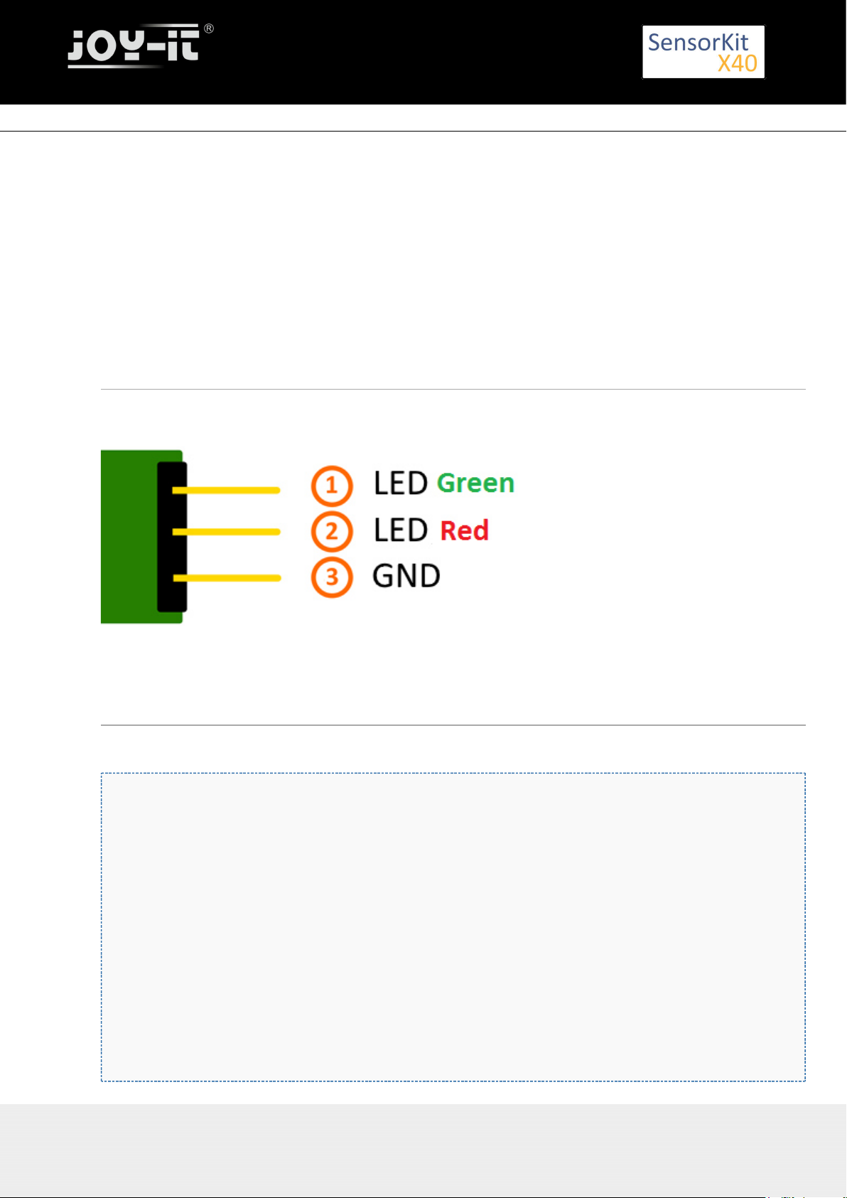
KY-011 2-Color (Red+Green) 5mm LED module
KY-011 2-Color (Red+Green) 5mm LED module
Contents
1 Picture ................................................................................................................................................................. 1
2 Technical data / Short description ....................................................................................................................... 1
3 Pinout ................................................................................................................................................................... 2
4 Code example Arduino ......................................................................................................................................... 2
5 Code example Raspberry Pi ................................................................................................................................. 3
Picture
Technical data / Short description
LED module which provides a red and a green LED. These LEDs are connected with a common cathode.
Resistors are needed for different input voltages.
Vf [typ]= 2,0-2,5V
If= 20mA
Pre-resistors:
Export: 16.06.2017 Copyright by Joy-IT - Published under CC BY-NC-SA 3.0 Page 46 of 214
Page 47
KY-011 2-Color (Red+Green) 5mm LED module
Rf (3,3V) [ ]= 120ΩGreen
Rf (3,3V) [ ]= 120ΩRed
[for example using ARM CPU-Core based microcontroller like Raspbarry Pi]
Rf (5V) [ ] = 220ΩGreen
Rf (5V) [ ] = 220ΩRed
[for example using Atmel Atmega based microcontroller like Arduino]
Pinout
Export: 16.06.2017 Copyright by Joy-IT - Published under CC BY-NC-SA 3.0 Page 47 of 214
Code example Arduino
Code example ON/OFF
int Led_Red = 10;
int Led_Green = 11;
void setup ()
{
// Output pin initialization for the LEDs
pinMode (Led_Red, OUTPUT);
pinMode (Led_Green, OUTPUT);
}
void loop () //Main program loop
{
digitalWrite (Led_Red, HIGH); // LED will be switched on
digitalWrite (Led_Green, LOW); // LED will be switched off
delay (3000); // Waitmode for 3 seconds
digitalWrite (Led_Red, LOW); // LED will be switched off
digitalWrite (Led_Green, HIGH); // LED will be switched on
delay (3000); // Waitmode for another 3 seconds in which the status of the LEDs are shifted.
}
Example program ON/OFF download:
Page 48

KY-011 2-Color (Red+Green) 5mm LED module
Example program ON/OFF download:
KY-011_LED_ON-OFF
Code example PWM
You can regulate the brightness of the LEDs via pulse-width modulation. The LEDs will be switched ON and
OFF for specific time periods, in which the relation between ON and OFF leads to a relative brightness,
because of the Inertia of the human eyesight, the human eye interprets the ON/OFF as a brightness change.
For more information to that theme visit:[ ]Artikel von mikrokontroller.net
This module provides a few LEDs - with the overlay of the different brightness levels, you can create
different colors. This will be shown in the following code example.
int Led_Red = 10;
int Led_Green = 11;
int val;
void setup () {
// Output pin initialization for the LEDs
pinMode (Led_Red, OUTPUT);
pinMode (Led_Green, OUTPUT);
}
void loop () {
// In this for loop, the two LEDs will get different PWM-Values.
// Via mixing the brightness of the different LEDs, you will get different colors.
for (val = 255; val> 0; val--)
{
analogWrite (Led_Green, val);
analogWrite (Led_Red, 255-val);
delay (15);
}
// You will go backwards through the color range in this second loop.
for (val = 0; val <255; val++)
{
analogWrite (Led_Green, val);
analogWrite (Led_Red, 255-val);
delay (15);
}
}
Example program PWM download:
KY-011_PWM
Connections Arduino:
LED
Green = [Pin 10]
LED Red = [Pin 11]
Sensor GND = [Pin GND]
Code example Raspberry Pi
Code example ON/OFF
Export: 16.06.2017 Copyright by Joy-IT - Published under CC BY-NC-SA 3.0 Page 48 of 214
Page 49

KY-011 2-Color (Red+Green) 5mm LED module
Export: 16.06.2017 Copyright by Joy-IT - Published under CC BY-NC-SA 3.0 Page 49 of 214
# Needed modules will be imported and configured.
import RPi.GPIO as GPIO
import time
GPIO.setmode(GPIO.BCM)
# Output pin declaration for the LEDs.
LED_Red = 5
LED_Green = 4
GPIO.setup(LED_Red, GPIO.OUT, initial= GPIO.LOW)
GPIO.setup(LED_Green, GPIO.OUT, initial= GPIO.LOW)
print "LED-Test [press ctrl+c to end the test]"
# Main program loop
try:
while True:
print("LED Red will be on for 3 seconds")
GPIO.output(LED_Red,GPIO.HIGH) #LED will be switched on
GPIO.output(LED_Green,GPIO.LOW) #LED will be switched off
time.sleep(3) # Waitmode for 3 seconds
print("LED Green will be on for 3 seconds")
GPIO.output(LED_Red,GPIO.LOW) #LED will be switched off
GPIO.output(LED_Green,GPIO.HIGH) #LED will be switched on
time.sleep(3) #Waitmode for 3 seconds in which the LEDs are shifted
# Scavenging work after the end of the program
except KeyboardInterrupt:
GPIO.cleanup()
Example program ON/OFF download
KY011_RPI_ON-OFF
To start, enter the command:
sudo python KY011_RPI_ON-OFF.py
Code example PWM
You can regulate the brightness of the LEDs via pulse-width modulation. The LEDs will be switched ON and
OFF of for specific time periods, in which the relation between ON and OFF leads to a relative brightness,
because of the Inertia of the human eyesight, the human eye interprets the ON/OFF as a brightness change.
For more information to that theme visit:[Artikel von mikrokontroller.net]
This module provides a few LEDs - with the overlay of the different brightness levels, you can create
different colors. This will be shown in the following code example. At the Raspberry Pi, only one HardwarePWM channel is carried out unrestricted to the GPIO pins, why we have used Software-PWM at this example
# Needed modules will be imported and configured
import random, time
import RPi.GPIO as GPIO
GPIO.setmode(GPIO.BCM)
# Output pin declaration for the LEDs.
LED_Red = 5
LED_Green = 4
# Set pins to output mode
GPIO.setup(LED_Red, GPIO.OUT)
Page 50

KY-011 2-Color (Red+Green) 5mm LED module
GPIO.setup(LED_Red, GPIO.OUT)
GPIO.setup(LED_Green, GPIO.OUT)
Freq = 100 #Hz
# The specific colors will be initialized.
RED = GPIO.PWM(LED_Red, Freq)
GREEN = GPIO.PWM(LED_Green, Freq)
RED.start(0)
GREEN.start(0)
# This function generate the actually color
# You can change the color with the specific color variable.
# After the configuration of the color is finished, you will time.sleep to
# configure how long the specific will be displayed.
def LED_color(Red, Green, pause):
RED.ChangeDutyCycle(Red)
GREEN.ChangeDutyCycle(Green)
time.sleep(pause)
RED.ChangeDutyCycle(0)
GREEN.ChangeDutyCycle(0)
print "LED-Test [press ctrl+c to end the test]"
# Main program loop:
# The task of this loop is to create for every single color an own variable.
# By mixing the brightness levels of the colors, you will get a color gradient.
try:
while True:
for x in range(0,2):
for y in range(0,2):
print (x,y)
for i in range(0,101):
LED_color((x*i),(y*i),.02)
# Scavenging work after the end of the program
except KeyboardInterrupt:
GPIO.cleanup()
Example program PWM download:
Media:KY011_RPI_PWM.zip
To start, enter the command:
sudo python KY011_RPI_PWM.py
ConnectionsRaspberry Pi:
LED
Green = GPIO4 [Pin 16]
LEDRed = GPIO5 [Pin 18]
Sensor GND = GND [Pin 6]
Export: 16.06.2017 Copyright by Joy-IT - Published under CC BY-NC-SA 3.0 Page 50 of 214
Page 51

KY-012 Active Piezo-Buzzer module
KY-012 Active Piezo-Buzzer module
Contents
1 Pictures ................................................................................................................................................................ 1
2 Technical data / Short description ....................................................................................................................... 1
3 Pinout ................................................................................................................................................................... 2
4 Code example Arduino ......................................................................................................................................... 2
5 Code example Raspberry Pi ................................................................................................................................. 2
Pictures
Technical data / Short description
This Buzzer creates a sound with a frequency of 2,5kHz.
The active Buzzer-module doesn't need a square wave, unlike the passiv module (KY-006), to create a
sound. If it gets a minimum Voltage of 3.3V at its signal pin, the buzzer will create the square wave by itself.
Export: 16.06.2017 Copyright by Joy-IT - Published under CC BY-NC-SA 3.0 Page 51 of 214
Page 52

Pinout
Code example Arduino
In this example, you will see how the buzzer will be ON for 4 seconds and then will be OFF for 2 seconds.
int Buzzer = 13;
void setup ()
{
pinMode (Buzzer, OUTPUT); // Output pin initialization for the buzzer
}
void loop () //Main program loop
{
digitalWrite (Buzzer, HIGH); // Buzzer will be on
delay (4000); // Waitmode for 4 seconds
digitalWrite (Buzzer, LOW); // Buzzer will be off
delay (2000); // Waitmode for another 2 seconds in which the buzzer will be off
}
Connections Arduino:
Sensor Signal = [Pin 13]
Sensor[N.C] =
Sensor GND = [Pin GND]
Example program download:
KY-006-RPI_PWM
Code example Raspberry Pi
In this example, you will see how, with a defined output pin, the buzzer will be ON for 4 seconds and then
will be OFF for 2 seconds.
Export: 16.06.2017 Copyright by Joy-IT - Published under CC BY-NC-SA 3.0 Page 52 of 214
KY-012 Active Piezo-Buzzer module
Page 53

KY-012 Active Piezo-Buzzer module
import RPi.GPIO as GPIO
import time
GPIO.setmode(GPIO.BCM)
# Output pin declaration for the Buzzer.
Buzzer_PIN = 24
GPIO.setup(Buzzer_PIN, GPIO.OUT, initial= GPIO.LOW)
print ("Buzzer-test [press ctrl+c to end the test]")
# Main program loop
try:
while True:
print("Buzzer will be on for 4 seconds")
GPIO.output(Buzzer_PIN,GPIO.HIGH) #Buzzer will be switched on
time.sleep(4) #Waitmode for 4 seconds
print("Buzzer wil be off for 4 seconds")
GPIO.output(Buzzer_PIN,GPIO.LOW) #Buzzer will be switched off
time.sleep(2) #Waitmode for another 2 seconds in which the buzzer will be off
# Scavenging work after the end of the program
except KeyboardInterrupt:
GPIO.cleanup()
ConnectionsRaspberry Pi:
Sensor Signal = GPIO24 [Pin 18]
Sensor [+V] = 3.3V [Pin 1]
Sensor GND = GND [Pin 6]
Example program download
KY-012_Buzzer_RPi
To start, enter the command:
sudo python KY-012_Buzzer_RPi.py
Export: 16.06.2017 Copyright by Joy-IT - Published under CC BY-NC-SA 3.0 Page 53 of 214
Page 54

KY-013 Temperature-Sensor module
KY-013 Temperature-Sensor module
Contents
1 Picture ................................................................................................................................................................. 1
2 Technical data / Short description ....................................................................................................................... 1
3 Pinout ................................................................................................................................................................... 3
4 Code example Arduino ......................................................................................................................................... 3
5 Code example Raspberry Pi ................................................................................................................................. 4
Picture
Technical data / Short description
Temperature measuring range: -55°C / +125°C
This module provides a NTC thermistor - it will have a lower resistant on higher temperatures.
Export: 16.06.2017 Copyright by Joy-IT - Published under CC BY-NC-SA 3.0 Page 54 of 214
Page 55

KY-013 Temperature-Sensor module
You can draw near to the resistant change via maths and convert it into a linear course. With that you can
determine the temperature coefficient (addicted from resistant change to temperature change). With that
you can determine the actual temperature if you know the current resistance.
This resistor can be determinded via voltage devider, where a known voltage splits up between a known
resistor and an unknown (variable) resistor.
With that Voltage you can determine the resistance of the resistor - you can see the full calculation in the
example below.
Export: 16.06.2017 Copyright by Joy-IT - Published under CC BY-NC-SA 3.0 Page 55 of 214
Page 56

KY-013 Temperature-Sensor module
Export: 16.06.2017 Copyright by Joy-IT - Published under CC BY-NC-SA 3.0 Page 56 of 214
Pinout
Code example Arduino
The program measures the actual voltage from the NTC, calculate the temperature and translates the result
to °C for the serial output.
#include <math.h>
int sensorPin = A5; // Declaration of the input pin
// These function translates the recorded analog measurement
double Thermistor(int RawADC)
{
double Temp;
Temp = log(10000.0 * ((1024.0 / RawADC - 1)));
Temp = 1 /(0.001129148 + (0.000234125 + (0.0000000876741 * Temp * Temp)) * Temp);
Temp = Temp - 273.15; // convert from Kelvin to Celsius
return Temp;
}
// Serial output in 9600 Baud
void setup()
Page 57

KY-013 Temperature-Sensor module
void setup()
{
Serial.begin(9600);
}
// The program measures the current voltage value on the NTC
// and translates it intp °C for the serial output
void loop()
{
int readVal = analogRead(sensorPin);
double temp = Thermistor(readVal);
// Output on the serial interface
Serial.print("Current temperature is:");
Serial.print(temp);
Serial.print(char(186)); //Output <°> Symbol
Serial.println("C");
Serial.println("---------------------------------------");
delay(500);
}
Connections Arduino:
Sensor +V = [Pin 5V]
Sensor GND = [Pin GND]
Sensor Signal = [Pin A5]
Example program Download
KY-013_TemperatureSensor
Code example Raspberry Pi
!! Attention!! Analog Sensor!! Attention!!
Unlike the Arduino, the Raspberry Pi doesn't provide an ADC (Analog Digital Converter) on its Chip. This
limits the Raspbery Pi if you want to use a non digital Sensor.
To evade this, use our with the module, which provides a 16 Bit ADC, which can be
Sensorkit X40 KY-053
used with the Raspberry Pi, to upgrade it with 4 additional analog input pins. This module is connected via
I2C to the Raspberry Pi.
It measures the analog data and converts it into a digital signal which is suitable for the Raspberry Pi.
So we recommend to use the KY-053 ADC if you want to use analog sensors along with the Raspberry Pi.
For more information please look at the infosite: KY-053 Analog Digital Converter
!! Attention!! Analog Sensor!! Attention!!
The program uses the specific ADS1x15 and I2C python-libraries from the company Adafruit to control the
ADS1115 ADC. You can find these here: [ ] https://github.com/adafruit/Adafruit-Raspberry-Pi-Python-Code
published under the BSD-License[ ]. You can find the needed libraries in the lower download package.Link
Export: 16.06.2017 Copyright by Joy-IT - Published under CC BY-NC-SA 3.0 Page 57 of 214
Page 58

KY-013 Temperature-Sensor module
Export: 16.06.2017 Copyright by Joy-IT - Published under CC BY-NC-SA 3.0 Page 58 of 214
### Copyright by Joy-IT
### Published under Creative Commons Attribution-NonCommercial-ShareAlike 3.0 Unported License
### Commercial use only after permission is requested and granted
###
### KY-053 Analog Digital Converter - Raspberry Pi Python Code Example
###
# This code is using the ADS1115 and the I2C Python Library for Raspberry Pi
# This was published on the following link under the BSD license
# [https://github.com/adafruit/Adafruit-Raspberry-Pi-Python-Code]
from Adafruit_ADS1x15 import ADS1x15
from time import sleep
# import needed modules
import math, signal, sys, os
import RPi.GPIO as GPIO
GPIO.setmode(GPIO.BCM)
GPIO.setwarnings(False)
# initialise variables
delayTime = 0.5 # in Sekunden
# assigning the ADS1x15 ADC
ADS1015 = 0x00 # 12-bit ADC
ADS1115 = 0x01 # 16-bit
# choosing the amplifing gain
gain = 4096 # +/- 4.096V
# gain = 2048 # +/- 2.048V
# gain = 1024 # +/- 1.024V
# gain = 512 # +/- 0.512V
# gain = 256 # +/- 0.256V
# choosing the sampling rate
# sps = 8 # 8 Samples per second
# sps = 16 # 16 Samples per second
# sps = 32 # 32 Samples per second
sps = 64 # 64 Samples per second
# sps = 128 # 128 Samples per second
# sps = 250 # 250 Samples per second
# sps = 475 # 475 Samples per second
# sps = 860 # 860 Samples per second
# assigning the ADC-Channel (1-4)
adc_channel_0 = 0 # Channel 0
adc_channel_1 = 1 # Channel 1
adc_channel_2 = 2 # Channel 2
adc_channel_3 = 3 # Channel 3
# initialise ADC (ADS1115)
adc = ADS1x15(ic=ADS1115)
# temperature calculation function
def calcTemp(voltage):
temperature = math.log((10000/voltage)*(3300-voltage))
temp = (0.0000000876741 * temperature * temperature)
temperature = 1 / (0.001129148 + (0.000234125 + temp) * temperature);
temperature = temperature - 273.15;
return temperature
Page 59

KY-013 Temperature-Sensor module
# print to console
print "Channel 0:", temp0, "C"
print "Channel 1:", temp1, "C"
print "Channel 2:", temp2, "C"
print "Channel 3:", temp3, "C"
print "---------------------------------------"
sleep(delayTime)
except KeyboardInterrupt:
GPIO.cleanup()
Connections Raspberry Pi:
Sensor
+V = 3,3V [Pin 1 (RPi)]
GND = GND [Pin 06 (RPi)]
analog Signal = Analog 0 [Pin A0 (ADS1115 - KY-053)]
ADS1115 - KY-053:
VDD = 3,3V [Pin 17]
GND = GND [Pin 09]
SCL = GPIO03 / SCL [Pin 05]
SDA = GPIO02 / SDA [Pin 03]
A0 = s.o. [Sensor: analog Signal]
Example program download
KY-013_Temperature-Sensor_RPi
To start, enter the command:
sudo python KY-013_RPi_TemperaturSensor.py
Export: 16.06.2017 Copyright by Joy-IT - Published under CC BY-NC-SA 3.0 Page 59 of 214
# ########
# Main Loop
# ########
# Reading the values from the input pins and print to console
try:
while True:
#read voltage-value and calculate temperature
temp0 = round(calcTemp(adc.readADCSingleEnded(adc_channel_0, gain, sps)), 2)
temp1 = round(calcTemp(adc.readADCSingleEnded(adc_channel_1, gain, sps)), 2)
temp2 = round(calcTemp(adc.readADCSingleEnded(adc_channel_2, gain, sps)), 2)
temp3 = round(calcTemp(adc.readADCSingleEnded(adc_channel_3, gain, sps)), 2)
Page 60

KY-015 Combi-Sensor Temperature+Humidity
KY-015 Combi-Sensor Temperature+Humidity
Contents
1 Picture ................................................................................................................................................................. 1
2 Technical data / Short description ....................................................................................................................... 1
3 Pinout ................................................................................................................................................................... 2
4 Software example Arduino ................................................................................................................................... 2
5 Software example Raspberry Pi ........................................................................................................................... 3
Picture
Technical data / Short description
Chipset: DHT11 | Communication protocol: 1-wire measuring range Humidity 20-90%RH measuring
termperature: 0-50°C
Advantages of the sensor are the combination between temperature measurment and humidity
measurements in one compact design - the disadvantage is the low sampling rate of the measurement, you
are only able to get a new result every 2 seconds - so thid sensor is better to use for long period
measurements.
Export: 16.06.2017 Copyright by Joy-IT - Published under CC BY-NC-SA 3.0 Page 60 of 214
Page 61

Pinout
Software example Arduino
This sensor is not sending it's measurements analog.
The measured data is transferred digital.
The best wayto use this sensor is with the Adafruit_DHT library from the company Adafruit which is
published under the following under the OpenSource .Link MIT-Lizenz
The example below is using this library - for this we advise to download it from Github, to copy and to unzip
it in the Arduino-library folder which you can find under the path C:\user\[Username]
\documents\arduino\libraries by default. You can use it then for this and the following project examples. It is
also included in the download package below.
// Adafruit_DHT library will be included
#include "DHT.h"
// You can declare the input pin here
#define DHTPIN 2
// The sensor will be initialized here
#define DHTTYPE DHT11 // DHT 11
DHT dht(DHTPIN, DHTTYPE);
void setup()
{
Serial.begin(9600);
Serial.println("KY-015 test - temperature and humidity-test:");
// Mearsurement will be started
dht.begin();
}
// Main program loop
// The program will be started and the measurements will be read by it.
// It takes a break between every measurement to take new values.
void loop() {
Export: 16.06.2017 Copyright by Joy-IT - Published under CC BY-NC-SA 3.0 Page 61 of 214
KY-015 Combi-Sensor Temperature+Humidity
Page 62

KY-015 Combi-Sensor Temperature+Humidity
// Two second break between measurements
delay(2000);
// Measurement of humidity
float h = dht.readHumidity();
// Measurement of temperature
float t = dht.readTemperature();
// The measurements will be tested of errors here
// If an error is detected, an error message will be displayed
if (isnan(h) || isnan(t)) {
Serial.println("Error while reading the sensor");
return;
}
// Output at the serial console
Serial.println("-----------------------------------------------------------");
Serial.print("Humidity: ");
Serial.print(h);
Serial.print(" %\t");
Serial.print("temperature: ");
Serial.print(t);
Serial.print(char(186)); //Output <°> symbol
Serial.println("C ");
Serial.println("-----------------------------------------------------------");
Serial.println(" ");
}
Please notice, the sensor will only get a new measurement value after 2 seconds. Because of
that it is better to use it for long period measurements.
Example program download:
KY-015-Sensor-Temperature-Moisture
Connections Arduino:
GND = [Pin GND]
+V = [Pin 5V]
Signal = [Pin D2]
Software example Raspberry Pi
To control the DHT11-sensor, the Adafruit_python_library from the company Adafruit will be used in our
example. This library is published under the following with the .Link MIT OpenSource-Lizenz
The library has to be installed before using:
At first, you need to make sure that your system is able to compile Python extensions.
sudo apt-get update
sudo apt-get install build-essential python-dev
Then you have to install the Github-sofware on the Raspberry Pi if it is not already done:
sudo apt-get install git
Export: 16.06.2017 Copyright by Joy-IT - Published under CC BY-NC-SA 3.0 Page 62 of 214
Page 63

KY-015 Combi-Sensor Temperature+Humidity
You can download and unzip the current version of the library with the command...
git clone https://github.com/adafruit/Adafruit_Python_DHT.git
After that you need to enter the downloaded folder with...
cd Adafruit_Python_DHT/
... and install the library with ...
sudo python setup.py install
In order that the Raspberry Pi can communicate with the sensor via I2C-bus, you have to activate the I2C
function from the Raspberry Pi.
For this, you have to append the following line to the end of the file "/boot/config.txt":
dtparam=i2c_arm=on
You can edit the file with the command:
sudo nano /boot/config.txt
You can save and close the file with the key sequence [ctrl+x -> y -> enter].
Furthermore you need additional libraries to use I2C with python. To install it use the following command:
sudo apt-get install python-smbus i2c-tools -y
You can use the following python code example now. The program starts the measurement at the sensor
and shows the measurements of air pressure, temperature and the highness above sea level.
#!/usr/bin/python
# coding=utf-8
# Needed modules will be imported
import RPi.GPIO as GPIO
import Adafruit_DHT
import time
# The break of 2 seconds will be configured here
sleeptime = 2
# Sensor should be set to Adafruit_DHT.DHT11,
# Adafruit_DHT.DHT22, or Adafruit_DHT.AM2302.
DHTSensor = Adafruit_DHT.DHT11
# The pin which is connected with the sensor will be declared here
GPIO_Pin = 23
print('KY-015 sensortest - temperature and humidity')
Export: 16.06.2017 Copyright by Joy-IT - Published under CC BY-NC-SA 3.0 Page 63 of 214
Page 64

KY-015 Combi-Sensor Temperature+Humidity
Example download
KY-015-RPi_Kombi-Sensor_Temperatur_Feuchtigkeit
To start with the command:
sudo python KY-015-RPi_Kombi-Sensor_Temperatur_Feuchtigkeit.py
Export: 16.06.2017 Copyright by Joy-IT - Published under CC BY-NC-SA 3.0 Page 64 of 214
try:
while(1):
# Measurement will be started and the result will be written into the variables
humid, temper = Adafruit_DHT.read_retry(DHTSensor, GPIO_Pin)
print("-----------------------------------------------------------------")
if humid is not None and temper is not None:
# The result will be shown at the console
print('temperature = {0:0.1f}°C | rel. humidity = {1:0.1f}%'.format(temper, humid))
# Because of the OS, the Raspberry Pi has problems with realtime measurements.
# It is possible that, because of timing problems, the communication fails.
# a message will be displayed - the result will be shown at next try.
else:
print('Error while reading - please wait for the next try!')
print("-----------------------------------------------------------------")
print("")
time.sleep(sleeptime)
# Scavenging work after the end of the program
except KeyboardInterrupt:
GPIO.cleanup()
Please notice, the sensor will only get a new measurement value after 2 seconds. Because of
that it is better to use it for long period measurements.
Connections Raspberry Pi:
GND = GND [Pin 06]
+V = 3,3V [Pin 01]
Signal = GPIO23 [Pin 16]
Page 65

KY-016 RGB 5mm LED module
KY-016 RGB 5mm LED module
Contents
1 Picture ................................................................................................................................................................. 1
2 Technical data / Short description ....................................................................................................................... 1
3 Pinout ................................................................................................................................................................... 2
4 Code example Arduino ......................................................................................................................................... 2
5 Code example Raspberry Pi ................................................................................................................................. 4
Picture
Technical data / Short description
LED-module which includes a red, blue and green LED. These are connected by a common cathode.
An additional resistor might be necessary for some voltages.
Vf [ ]= 1,8V
Red
Vf [ , ]= 2,8VGreen Blue
If= 20mA
Vorwiderstände:
Export: 16.06.2017 Copyright by Joy-IT - Published under CC BY-NC-SA 3.0 Page 65 of 214
Page 66

KY-016 RGB 5mm LED module
Rf (3,3V) [ ]= 100ΩGreen
Rf (3,3V) [ ]= 180ΩRed
Rf (3,3V) [ ]= 100ΩBlue
[e.g. by using with ARM CPU-core based microcontroller like Raspberry-Pi]
Rf (5V) [ ] = 100ΩGreen
Rf (5V) [ ] = 180ΩRed
Rf (5V) [ ] = 100Ω
Blue
[e.g. by using with Atmel Atmega based mocrocontroller like Arduino]
Pinout
Code example Arduino
Code example ON/OFF
In this example you will see how the LED is turnedon by anoutput pin, in a 3 second clock pulse.
int Led_Red = 10;
int Led_Green = 11;
int Led_Blue = 12;
void setup ()
{
// Output pin initialization for the LEDs
pinMode (Led_Red, OUTPUT);
pinMode (Led_Green, OUTPUT);
pinMode (Led_Blue, OUTPUT);
}
void loop () //main program loop
{
digitalWrite (Led_Red, HIGH); // LED will be switched ON
digitalWrite (Led_Green, LOW); // LED will be switched OFF
digitalWrite (Led_Blue, LOW); // LED will be switched OFF
delay (3000); // Waitmode for 3 seconds
Export: 16.06.2017 Copyright by Joy-IT - Published under CC BY-NC-SA 3.0 Page 66 of 214
Page 67

KY-016 RGB 5mm LED module
digitalWrite (Led_Rot, LOW); // LED will be switched OFF
digitalWrite (Led_Gruen, HIGH); // LED wwill be switched ON
digitalWrite (Led_Blau, LOW); // LED will be switched OFF
delay (3000); // Waitmode for another 3 seconds in which the LEDs will be shifted.
digitalWrite (Led_Rot, LOW); // LED will be switched OFF
digitalWrite (Led_Gruen, LOW); // LED will be switched OFF
digitalWrite (Led_Blau, HIGH); // LED will be switched ON
delay (3000); // Waitmode for another 3 seconds in which the LEDs will be shifted.
}
Example program ON/OFF download:
KY-016_LED_ON-OFF.zip
Code example PWM
You can regulate the brightness of the LEDs via pulse-width modulation. The LEDs will be switched ON and
OFF for specific time periods, in which the relation between ON and OFF leads to a relative brightness,
because of the Inertia of the human eyesight, the human eye interprets the ON/OFF as a brightness change.
For more information to that theme visit:[ ].
Artikel von mikrokontroller.net
This module provides a few LEDs - with the overlay of the different brightness levels, you can create
different colors. This will be shown in the following code example.
int Led_Red = 10;
int Led_Green = 11;
int Led_Blue = 12;
int val;
void setup () {
// Output pin initialization for the LEDs
pinMode (Led_Red, OUTPUT);
pinMode (Led_Green, OUTPUT);
pinMode (Led_Blue, OUTPUT);
}
void loop () {
// In this for-loop, the 3 LEDs will get different PWM-values
// Via mixing the brightness of the different LEDs, you will get different colors.
for (val = 255; val> 0; val--)
{
analogWrite (Led_Blue, val);
analogWrite (Led_Green, 255-val);
analogWrite (Led_Red, 128-val);
delay (1);
}
// You will go backwards through the color range in this second for loop.
for (val = 0; val <255; val++)
{
analogWrite (Led_Blue, val);
analogWrite (Led_Green, 255-val);
analogWrite (Led_Red, 128-val);
delay (1);
}
}
Example program PWM download:
Export: 16.06.2017 Copyright by Joy-IT - Published under CC BY-NC-SA 3.0 Page 67 of 214
Page 68

KY-016 RGB 5mm LED module
KY-016_PWM.zip
Connections Arduino:
LED
Red = [Pin 10]
LED Green = [Pin 11]
LED Blue = [Pin 12]
Sensor GND = [Pin GND]
Code example Raspberry Pi
Code example ON/OFF
In this example you will see how the LED is turnedon by anoutput pin, in a 3 second clock pulse.
# Needed modules will be imported
import RPi.GPIO as GPIO
import time
GPIO.setmode(GPIO.BCM)
# The output pins will be declared, which are connected with the LEDs.
LED_RED = 6
LED_GREEN = 5
LED_BLUE = 4
GPIO.setup(LED_RED, GPIO.OUT, initial= GPIO.LOW)
GPIO.setup(LED_GREEN, GPIO.OUT, initial= GPIO.LOW)
GPIO.setup(LED_BLUE, GPIO.OUT, initial= GPIO.LOW)
print "LED-test [press ctrl+c to end]"
# main program loop
try:
while True:
print("LED RED is on for 3 seconds")
GPIO.output(LED_RED,GPIO.HIGH) #LED will be switched ON
GPIO.output(LED_GREEN,GPIO.LOW) #LED will be switched OFF
GPIO.output(LED_BLUE,GPIO.LOW) #LED will be switched OFF
time.sleep(3) # waitmode for 3 seconds
print("LED GREEN is on for 3 seconds")
GPIO.output(LED_RED,GPIO.LOW) #LED will be switched OFF
GPIO.output(LED_GREEN,GPIO.HIGH) #LED will be switched ON
GPIO.output(LED_BLUE,GPIO.LOW) #LED will be switched OFF
time.sleep(3) # waitmode for 3 seconds
print("LED BLUE is on for 3 seconds")
GPIO.output(LED_RED,GPIO.LOW) #LED will be switched OFF
GPIO.output(LED_GREEN,GPIO.LOW) #LED will be switched OFF
GPIO.output(LED_BLUE,GPIO.HIGH) #LED will be switched ON
time.sleep(3) #waitmode for 3 seconds
# Scavenging work after the end of the program
except KeyboardInterrupt:
GPIO.cleanup()
Example program ON/OFF download
To start, enter the command:
Export: 16.06.2017 Copyright by Joy-IT - Published under CC BY-NC-SA 3.0 Page 68 of 214
Page 69

KY-016 RGB 5mm LED module
sudo python KY016_RPI_ON-OFF.py
Code example PWM
You can regulate the brightness of the LEDs via pulse-width modulation. The LEDs will be switched ON and
OFF for specific time periods, in which the relation between ON and OFF leads to a relative brightness,
because of the Inertia of the human eyesight, the human eye interprets the ON/OFF as a brightness change.
For more information to that theme visit:[ ].Artikel von mikrokontroller.net
This module provides a few LEDs - with the overlay of the different brightness levels, you can create
different colors. This will be shown in the following code example. At the Raspberry Pi, only one HardwarePWM channel is carried out unrestricted to the GPIO pins, why we have used Software-PWM at this example.
# Needed modules will be imported and configured
import random, time
import RPi.GPIO as GPIO
GPIO.setmode(GPIO.BCM)
# Declaration of the output pins, which are connected with the LEDs
LED_Red = 6
LED_Green = 5
LED_Blue = 4
# Set pins to output mode
GPIO.setup(LED_Red, GPIO.OUT)
GPIO.setup(LED_Green, GPIO.OUT)
GPIO.setup(LED_Blue, GPIO.OUT)
Freq = 100 #Hz
# The different colors will be initialized
RED = GPIO.PWM(LED_Red, Freq)
GREEN = GPIO.PWM(LED_Green, Freq)
BLUE = GPIO.PWM(LED_Blue, Freq)
RED.start(0)
GREEN.start(0)
BLUE.start(0)
# This function generate the actually color
# You can change the color with the specific color variable
# After the configuration of the color if finished, you will use time.sleep to
# configure how long the specific color will be displayed
def LED_color(Red, Green, Blue, pause):
RED.ChangeDutyCycle(Red)
GREEN.ChangeDutyCycle(Green)
BLUE.ChangeDutyCycle(Blue)
time.sleep(pause)
RED.ChangeDutyCycle(0)
GREEN.ChangeDutyCycle(0)
print "LED-test [press ctrl+c to end]"
# Main program loop:
# The task of this loop is to create for every single color an own variable
# By mixing the brightness levels of the colors, you will get a color gradient.
try:
while True:
for x in range(0,2):
Export: 16.06.2017 Copyright by Joy-IT - Published under CC BY-NC-SA 3.0 Page 69 of 214
Page 70

KY-016 RGB 5mm LED module
for y in range(0,2):
for z in range(0,2):
print (x,y,z)
for i in range(0,101):
LED_color((x*i),(y*i),(z*i),.02)
# Scavenging work after the end of the program
except KeyboardInterrupt:
GPIO.cleanup()
Example program PWM download:
KY-016_RPi_PWM.zip
To start, enterthe command:
sudo python KY-016_RPi_PWM.py
Connections Raspberry Pi:
LED
Red = GPIO6 [Pin 22]
LEDGreen = GPIO5 [Pin 18]
LEDBlue = GPIO4 [Pin 16]
Sensor GND = GND [Pin 6]
Export: 16.06.2017 Copyright by Joy-IT - Published under CC BY-NC-SA 3.0 Page 70 of 214
Page 71

KY-017 Tilt switch module
KY-017 Tilt switch module
Contents
1 Picture ................................................................................................................................................................. 1
2 Technical data / Short description ....................................................................................................................... 1
3 Pinout ................................................................................................................................................................... 2
4 Code example Arduino ......................................................................................................................................... 2
5 Code example Raspberry Pi ................................................................................................................................. 3
Picture
Technical data / Short description
Depending on the angle, a switch connects the circuit.
Export: 16.06.2017 Copyright by Joy-IT - Published under CC BY-NC-SA 3.0 Page 71 of 214
Page 72

Pinout
Code example Arduino
This example will light up a LEDas soon as the tilt module is in the right angle.
The modules KY-011, KY-016 or KY-029 can be used as LED.
int Led = 13 ;// Declaration of the LED output pin
int Sensor = 10; // Declaration of the sensor input pin
int val; // temporary variable
void setup ()
{
pinMode (Led, OUTPUT) ; // Initialization output pin
pinMode (Sensor, INPUT) ; // Initialization sensor pin
}
void loop ()
{
val = digitalRead (Sensor) ; // The active signal at the sensor will be read
if (val == HIGH) // If a signal was noticed, the LED will be on.
{
digitalWrite (Led, LOW);
}
else
{
digitalWrite (Led, HIGH);
}
}
Connections Arduino:
LED + = [Pin 13]
LED - = [Pin GND]
Sensor Signal = [Pin 10]
Sensor+V = [Pin 5V]
Export: 16.06.2017 Copyright by Joy-IT - Published under CC BY-NC-SA 3.0 Page 72 of 214
KY-017 Tilt switch module
Page 73

KY-017 Tilt switch module
Export: 16.06.2017 Copyright by Joy-IT - Published under CC BY-NC-SA 3.0 Page 73 of 214
Sensor - = [Pin GND]
Example program download
SensorTest_Arduino_withoutPullUP
Code example Raspberry Pi
# Needed modules will be imported.
import RPi.GPIO as GPIO
import time
GPIO.setmode(GPIO.BCM)
# The input pin of the Sensor will be declared. The pullup resistor will be activated
GPIO_PIN = 24
GPIO.setup(GPIO_PIN, GPIO.IN)
print "Sensor-test [press ctrl+c to end]"
# This output function will be started at signal detection
def outFunction(null):
print("Signal detected")
# The output function will be activated after a signal was detected
GPIO.add_event_detect(GPIO_PIN, GPIO.FALLING, callback=outFunction, bouncetime=100)
# main program loop
try:
while True:
time.sleep(1)
# Scavenging work after the end of the program
except KeyboardInterrupt:
GPIO.cleanup()
Connections Raspberry Pi:
Signal = GPIO24 [Pin 18]
+V = 3,3V [Pin 1]
GND = GND [Pin 6]
Example program download
SensorTest_RPi_withoutPullUP
To start, enter the command:
sudo python SensorTest_RPi_withoutPullUP.py
Page 74

KY-018 Photoresistor module
KY-018 Photoresistor module
Contents
1 Picture ................................................................................................................................................................. 1
2 Technical data / Short description ....................................................................................................................... 1
3 Pinout ................................................................................................................................................................... 2
4 Code example Arduino ......................................................................................................................................... 2
5 Code example Raspberry Pi ................................................................................................................................. 3
Picture
Technical data / Short description
Includes a LDR-resistor (Light dependent resistor), which decreases its resistance at brighter surrounding.
You can determine the resistance of the resistor by using a voltage divider, where a known voltage will be
divided between a known and an unknown variable resistor. You can calculate the resistance with the
measured voltage - the code example below includes the exact calculation.
Export: 16.06.2017 Copyright by Joy-IT - Published under CC BY-NC-SA 3.0 Page 74 of 214
Page 75

Pinout
Export: 16.06.2017 Copyright by Joy-IT - Published under CC BY-NC-SA 3.0 Page 75 of 214
KY-018 Photoresistor module
Code example Arduino
The example will measure the current sensors voltage and calculates the current resisitance of the sensor.
int sensorPin = A5; // Declaration of the input pin
// Serial output in 9600 Baud
void setup()
{
Serial.begin(9600);
}
// The program measures the current voltage at the sensor ,
// takes the value of the known resistor and calculates the current resistance of the sensor.
// After that it show the result via serial output.
void loop()
{
// Current voltage will be measured...
int rawValue = analogRead(sensorPin);
float voltage = rawValue * (5.0/1023) * 1000;
float resitance = 10000 * ( voltage / ( 5000.0 - voltage) );
// and here it will be outputted via serial infterface
Serial.print("Voltage value:"); Serial.print(voltage); Serial.print("mV");
Serial.print(", Resistor value:"); Serial.print(resitance); Serial.println("Ohm");
Serial.println("---------------------------------------");
delay(500);
}
Connections Arduino:
Sensor GND = [Pin GND]
Sensor +V = [Pin 5V]
Sensor Signal = [Pin A5]
Page 76

KY-018 Photoresistor module
Example program download
Single_Analog_Sensor
Code example Raspberry Pi
!! Attention!! !!Analog Sensor Attention!!
Unlike the Arduino, the Raspberry Pi doesn't provide an ADC (Analog Digital Converter) on its Chip. This
limits the Raspbery Pi if you want to use a non digital Sensor.
To evade this, use our with the module, which provides a 16 Bit ADC, which can be
Sensorkit X40 KY-053
used with the Raspberry Pi, to upgrade it with 4 additional analog input pins. This module is connected via
I2C to the Raspberry Pi.
It measures the analog data and converts it into a digital signal which is suitable for the Raspberry Pi.
So we recommend to use the KY-053 ADC if you want to use analog sensors along with the Raspberry Pi.
For more information please look at the infosite:[[ ]]KY-053 Analog Digital Converter
# This code is using the ADS1115 and the I2C Python Library for Raspberry Pi
# This was published on the following link under the BSD license
# [https://github.com/adafruit/Adafruit-Raspberry-Pi-Python-Code]
from Adafruit_ADS1x15 import ADS1x15
from time import sleep
# import needed modules
import time, signal, sys, os
import RPi.GPIO as GPIO
GPIO.setmode(GPIO.BCM)
GPIO.setwarnings(False)
# initialise variables
delayTime = 0.5 # in Sekunden
# assigning the ADS1x15 ADC
Export: 16.06.2017 Copyright by Joy-IT - Published under CC BY-NC-SA 3.0 Page 76 of 214
!! Attention!! Analog Sensor !! Attention!!
The program uses the specific ADS1x15 and I2C python-libraries from the company Adafruit to control the
ADS1115 ADC. You can find these here:[https://github.com/adafruit/Adafruit-Raspberry-Pi-Python-Code]
published under the BSD-License[Link]. You can find the needed libraries in the lower download package.
The program measures the current voltage at the sensor, takes the value of the known resistor and
calculates with it the current resistance of the sensor.
After that it will show the result via serial output.
#######################################################################################
### Copyright by Joy-IT
### Published under Creative Commons Attribution-NonCommercial-ShareAlike 3.0 Unported License
### Commercial use only after permission is requested and granted
###
### KY-053 Analog Digital Converter - Raspberry Pi Python Code Example
###
#######################################################################################
Page 77

KY-018 Photoresistor module
Export: 16.06.2017 Copyright by Joy-IT - Published under CC BY-NC-SA 3.0 Page 77 of 214
ADS1015 = 0x00 # 12-bit ADC
ADS1115 = 0x01 # 16-bit
# choosing the amplifing gain
gain = 4096 # +/- 4.096V
# gain = 2048 # +/- 2.048V
# gain = 1024 # +/- 1.024V
# gain = 512 # +/- 0.512V
# gain = 256 # +/- 0.256V
# choosing the sampling rate
# sps = 8 # 8 Samples per second
# sps = 16 # 16 Samples per second
# sps = 32 # 32 Samples per second
sps = 64 # 64 Samples per second
# sps = 128 # 128 Samples per second
# sps = 250 # 250 Samples per second
# sps = 475 # 475 Samples per second
# sps = 860 # 860 Samples per second
# assigning the ADC-Channel (1-4)
adc_channel_0 = 0 # Channel 0
adc_channel_1 = 1 # Channel 1
adc_channel_2 = 2 # Channel 2
adc_channel_3 = 3 # Channel 3
# initialise ADC (ADS1115)
adc = ADS1x15(ic=ADS1115)
#######################################################################################
# ########
# Main Loop
# ########
# Reading the values from the input pins and print to console
try:
while True:
#read values
adc0 = adc.readADCSingleEnded(adc_channel_0, gain, sps)
adc1 = adc.readADCSingleEnded(adc_channel_1, gain, sps)
adc2 = adc.readADCSingleEnded(adc_channel_2, gain, sps)
adc3 = adc.readADCSingleEnded(adc_channel_3, gain, sps)
# print to console
print "Channel 0:", adc0, "mV "
print "Channel 1:", adc1, "mV "
print "Channel 2:", adc2, "mV "
print "Channel 3:", adc3, "mV "
print "---------------------------------------"
time.sleep(delayTime)
Page 78

KY-018 Photoresistor module
Analog Signal = Analog 0 [Pin A0 (ADS1115 - KY-053)]
ADS1115 - KY-053:
VDD = 3,3V [Pin 17]
GND = GND [Pin 09]
SCL = GPIO03 / SCL [Pin 05]
SDA = GPIO02 / SDA [Pin 03]
A0 = look above [Sensor: analog signal]
Example program download
KY-053_RPi_AnalogDigitalConverter
To start, enter the command:
sudo python RPi_Single_Analog_Sensor.py
Export: 16.06.2017 Copyright by Joy-IT - Published under CC BY-NC-SA 3.0 Page 78 of 214
Page 79

KY-019 5V Relais module
KY-019 5V Relais module
Contents
1 Picture ................................................................................................................................................................. 1
2 Technical data / Short description ....................................................................................................................... 1
3 Pinout ................................................................................................................................................................... 2
4 Code example Arduino ......................................................................................................................................... 2
5 Code example Raspberry Pi ................................................................................................................................. 3
Picture
Technical data / Short description
Voltage range: 240VAC / 10A | 28VDC / 10A A relay to switch higher voltages via 5V output.
!!!!! Caution!!!!!
Working with voltages over 30V and a main voltage (230V) can harm your body or kill you.
We advise you not to work with higher valtages unless you have the needed experience.
!!!!! Caution!!!!!
The output bar of the Relais has two output terminals.
Export: 16.06.2017 Copyright by Joy-IT - Published under CC BY-NC-SA 3.0 Page 79 of 214
Page 80

KY-019 5V Relais module
- The first one is tagged with NC for "normally closed" which means that it's connected through by default.
- The second one is tagged with NO for "normally open" wich means it's not connected through by default.
To switch both, you need a signal.
Pinout
Code example Arduino
The program imitates a direction indicator - it switchs the status of the output terminals in a specific time
period (delayTime).
int relay = 10; // Declaration of the pin which is connected with the relay
delayTime = 1 // The time which will be waited between the switches of the relay.
void setup ()
{
pinMode (relay, OUTPUT); // Declaration of the pin to output
}
Export: 16.06.2017 Copyright by Joy-IT - Published under CC BY-NC-SA 3.0 Page 80 of 214
Page 81

KY-019 5V Relais module
# Main program loop
try:
while True:
GPIO.output(RELAIS_PIN, True) # NO is now connected through
time.sleep(delayTime)
GPIO.output(RELAIS_PIN, False) # NC is now connected through
time.sleep(delayTime)
# Scavenging work after the end of the program
except KeyboardInterrupt:
GPIO.cleanup()
Connections Raspberry Pi:
Relais - = GND [Pin 06]
Relais + = 5V [Pin 2]
Relais Signal = GPIO24 [Pin 18]
// The program imitates a direction indicator
void loop ()
{
digitalWrite (relay, HIGH); // "NO" is now connected through
delay (delayTime * 1000);
digitalWrite (relay, LOW); // "NC" is now connected through
delay (delayTime * 1000);
}
Connections Arduino:
Sensor - = [Pin GND]
Sensor + = [Pin 5V]
Sensor Signal = [Pin 10]
Example program download
KY-019_Relais
Code example Raspberry Pi
The program imitates a direction indicator - it switchs the status of the output terminals in a specific time
period.
# Needed modules will be imported and configured
import RPi.GPIO as GPIO
import time
GPIO.setmode(GPIO.BCM)
# Declaration of the break between the changes of the relay status (in seconds)
delayTime = 1
# Declaration of the input pin which is connected with the sensor.
RELAIS_PIN = 21
GPIO.setup(RELAIS_PIN, GPIO.OUT)
GPIO.output(RELAIS_PIN, False)
print "Sensor-test [press ctrl+c to end]"
Export: 16.06.2017 Copyright by Joy-IT - Published under CC BY-NC-SA 3.0 Page 81 of 214
Page 82

KY-019 5V Relais module
Example program download
KY-019_RPi_Relais
To start, enter the command:
sudo python KY-019_RPi_Relais.py
Export: 16.06.2017 Copyright by Joy-IT - Published under CC BY-NC-SA 3.0 Page 82 of 214
Page 83

KY-020 Tilt switch module
KY-020 Tilt switch module
Contents
1 Pircture ................................................................................................................................................................ 1
2 Technical data / Short description ....................................................................................................................... 1
3 Pinout ................................................................................................................................................................... 2
4 Code example Arduino ......................................................................................................................................... 2
5 Code example Raspberry Pi ................................................................................................................................. 3
Pircture
Technical data / Short description
Depending on the angle,a switch connects the circuit.
Export: 16.06.2017 Copyright by Joy-IT - Published under CC BY-NC-SA 3.0 Page 83 of 214
Page 84

Pinout
Code example Arduino
This example will light up a LED after a sensor detected a signal.
the modules KY-011, KY-016 or KY-029 could be used as LED too for example.
int Led = 13 ;// Declaration of the LED output pin
int Sensor = 10; // Declaration of the sensor input pin
int val; // Temporary variable
void setup ()
{
pinMode (Led, OUTPUT) ; // Initialization output pin
pinMode (Sensor, INPUT) ; // Initialization sensor pin
}
void loop ()
{
val = digitalRead (Sensor) ; // The current signal at the sensor will be read
if (val == HIGH) // If a signal will be detected, the LED will light up
{
digitalWrite (Led, LOW);
}
else
{
digitalWrite (Led, HIGH);
}
}
Connections Arduino:
LED + = [Pin 13]
LED - = [Pin GND]
Sensor Signal = [Pin 10]
Sensor+V = [Pin 5V]
Export: 16.06.2017 Copyright by Joy-IT - Published under CC BY-NC-SA 3.0 Page 84 of 214
KY-020 Tilt switch module
Page 85

KY-020 Tilt switch module
Export: 16.06.2017 Copyright by Joy-IT - Published under CC BY-NC-SA 3.0 Page 85 of 214
Sensor - = [Pin GND]
Example program download
SensorTest_Arduino_withoutPullUP
Code example Raspberry Pi
# Needed modules will be imported and configured
import RPi.GPIO as GPIO
import time
GPIO.setmode(GPIO.BCM)
# Declaration of the input pin which is connected with the sensor.
GPIO_PIN = 24
GPIO.setup(GPIO_PIN, GPIO.IN)
print "Sensor-test [press ctrl+c to end]"
# This outFunction will be started at signal detection.
def outFunction(null):
print("Signal detected")
# The outFunction will be started after detecting of a signal (falling signal edge)
GPIO.add_event_detect(GPIO_PIN, GPIO.FALLING, callback=outFunction, bouncetime=100)
# Main program loop
try:
while True:
time.sleep(1)
# Scavenging work after the end of the program
except KeyboardInterrupt:
GPIO.cleanup()
Connections Raspberry Pi:
Signal = GPIO24 [Pin 18]
+V = 3,3V [Pin 1]
GND = GND [Pin 6]
Example program download
SensorTest_RPi_withoutPullUP
To start, enter the command:
sudo python SensorTest_RPi_withoutPullUP.py
Page 86

KY-021 Mini magnetic Reed module
KY-021 Mini magnetic Reed module
Contents
1 Picture ................................................................................................................................................................. 1
2 Technical data / Short description ....................................................................................................................... 1
3 Pinout ................................................................................................................................................................... 2
4 Code example Arduino ......................................................................................................................................... 2
5 Code example Raspberry Pi ................................................................................................................................. 3
Picture
Technical data / Short description
If the sensor is close to a magnetic field, the input pins are connected.
Export: 16.06.2017 Copyright by Joy-IT - Published under CC BY-NC-SA 3.0 Page 86 of 214
Page 87

Pinout
Code example Arduino
This example will activate a LED if the sensoris close to a magnetic field.
The modules KY-011, KY-016 or KY-029 can be used as a LED.
int Led = 13 ;// Declaration of the LED output pin.
int Sensor = 10; //Declaration of the sensor input pin
int val; // Temporary variable
void setup ()
{
pinMode (Led, OUTPUT) ; // Initialization output pin
pinMode (Sensor, INPUT) ; // Initialization sensor pin
}
void loop ()
{
val = digitalRead (Sensor) ; // The current signal at the sensor will be read
if (val == HIGH) // If a signal will be detected, the LED will light up.
{
digitalWrite (Led, LOW);
}
else
{
digitalWrite (Led, HIGH);
}
}
Connections Arduino:
LED + = [Pin 13]
LED - = [Pin GND]
Sensor Signal = [Pin 10]
Sensor+V = [Pin 5V]
Export: 16.06.2017 Copyright by Joy-IT - Published under CC BY-NC-SA 3.0 Page 87 of 214
KY-021 Mini magnetic Reed module
Page 88

KY-021 Mini magnetic Reed module
Export: 16.06.2017 Copyright by Joy-IT - Published under CC BY-NC-SA 3.0 Page 88 of 214
Sensor - = [Pin GND]
Example program download
SensorTest_Arduino_withoutPullUP
Code example Raspberry Pi
# Needed modules will be imported and configured
import RPi.GPIO as GPIO
import time
GPIO.setmode(GPIO.BCM)
# Declaration of the input pin which is connected with the sensor.
GPIO_PIN = 24
GPIO.setup(GPIO_PIN, GPIO.IN)
print "Sensor-test [press ctrl+c to end]"
# This outFunction will be started after a signal was detected.
def outFunction(null):
print("Signal detected")
# The outFunction will be started after a signal (falling signal edge) was detected.
GPIO.add_event_detect(GPIO_PIN, GPIO.FALLING, callback=outFunction, bouncetime=100)
# main program loop
try:
while True:
time.sleep(1)
# Scavenging work after the end of the program
except KeyboardInterrupt:
GPIO.cleanup()
Connections Raspberry Pi:
Signal = GPIO24 [Pin 18]
+V = 3,3V [Pin 1]
GND = GND [Pin 6]
Example program download
KY-021_mini-magnetic-reed_RPI
To start, enter the command:
sudo python SensorTest_RPi_withoutPullUP.py
Page 89

KY-022 Infrared receiver module
KY-022 Infrared receiver module
Contents
1 Picture ................................................................................................................................................................. 1
2 Technical data / Short description ....................................................................................................................... 1
3 Pinout ................................................................................................................................................................... 2
4 Code example Arduino ......................................................................................................................................... 2
5 Code example Raspberry Pi ................................................................................................................................. 4
5.1 Code example remote ................................................................................................................................ 4
5.2 Lirc Installation ........................................................................................................................................... 4
5.3 IR-Receiver Test ......................................................................................................................................... 6
5.4 Remote teach ............................................................................................................................................. 6
5.5 Sending command via Infrared Transmitter ............................................................................................... 8
Picture
Technical data / Short description
Carrier frequency: 38kHz - can receive infrared signals and transfers them to the digital signal out.
Additionally, the LED of this module will light up if an infrared signal is detected.
Export: 16.06.2017 Copyright by Joy-IT - Published under CC BY-NC-SA 3.0 Page 89 of 214
Page 90

Pinout
Code example Arduino
With both sensor modules, KY-005 and KY-022, you can build an infrared remote + infrared receiver system.
In order to do this, you will need the two sensor modules as well as two Arduinos.
The first one will handle the receiver system and the second one will handle the transmitter system.
An additional library is needed for this code example:
-[Arduino-IRremote] from | published under LGPLKen Shirriff
The library is in the package and has to be copied before the start into the library folder.
You will find it normally under the following path:
C:\User\[UserName]\Documents\Arduino\libraries
There are different infrared protocolls to send data. In this example we use the RC5 protocol. The used
library "Arduino-IRremote" converts the data independently. The library has additional protocolls, they are
marked in this documentation.
Code for the receiver:
// Arduino-IRremote library will be added
#include <IRremote.h>
#include <IRremoteInt.h>
// You can declare the input pin for the signal output of the KY-022 here
int RECV_PIN = 11;
// Arduino-IRremote library will be initialized
IRrecv irrecv(RECV_PIN);
decode_results results;
Export: 16.06.2017 Copyright by Joy-IT - Published under CC BY-NC-SA 3.0 Page 90 of 214
KY-022 Infrared receiver module
Page 91

KY-022 Infrared receiver module
Connections Arduino 1 [Receiver]:
KY-022
Signal = [Pin 11]
+V = [Pin 5V]
GND = [Pin GND]
Export: 16.06.2017 Copyright by Joy-IT - Published under CC BY-NC-SA 3.0 Page 91 of 214
void setup()
{
Serial.begin(9600);
irrecv.enableIRIn(); // Infrared receiver will start
}
// main program loop
void loop() {
// It will be checked if the receiver has gotten a signal.
if (irrecv.decode(&results)) {
//At signal input, the received and decoded signal will show via serial console.
Serial.println(results.value, HEX);
irrecv.resume();
}
}
Code for the transmitter:
//Arduino-IRremote library will be added
#include <IRremote.h>
#include <IRremoteInt.h>
//...and here initialized
IRsend irsend;
// The configuration of the output pin will be made by the library
// The output pin is a different one for different arduinos
// Arduino UNO: Output = D3
// Arduino MEGA: Output = D9
// You will find a full list of output pins on the website:
// http://z3t0.github.io/Arduino-IRremote/
void setup()
{
}
// main program loop
void loop() {
// The transmitter sends the signal A90 (hex. dezimal form) in the encoding "RC5"
// It will be transmitted 3 times after that it will make a 5 second break
for (int i = 0; i < 3; i++) {
irsend.sendRC5(0xA90, 12); //[12] Bit-length signal (hex A90=1010 1001 0000)
delay(40);
}
delay(5000); // 5 second break between the sending impulses
}
Example program download:
KY-005_KY-022_Infrared-Modules_ARD
Page 92

KY-022 Infrared receiver module
Connections Arduino 2 [Transmitter]:
KY-005
Signal = [Pin 3 (Arduino Uno) | Pin 9 (Arduino Mega)]
GND+resistor = [Pin GND*]
GND = [Pin GND]
* Only if resistor was soldered to the circuit board.
Code example Raspberry Pi
Code example remote
Because of its progressive processor architecture, the Raspberry Pi has a big advantage, compared to the
Arduino.
It can run a full Linux OS. With help of an infrared-receiver, it can not only transmit simple data signals,
furthermore it can control complete programs via remote.
To setup an infrared control system, we recommend to use the Linux software "lirc" ( published under the
LGPL- ).
Website
In the following section, we show you how to use lirc and how the remotely send the learned signals via
infrared.
On this purpose, the module KY-005 will be used as an infrared-transmitter and the KY-022 will be used as
an infrared-receiver.
Connections Raspberry Pi:
KY-005
Signal = GPIO17 [Pin 11]
GND+resistor = GND* [Pin 9]
GND = GND [Pin 6]
* Only if a resistor was soldered to the module
KY-022
Signal = GPI18 [Pin 12]
+V = 3,3V [Pin 17]
GND = GND [Pin 25]
Lirc Installation
Open a terminal at the desktop or use SSH to log into your Raspberry Pi. To install lirc, enter the following
command:
Export: 16.06.2017 Copyright by Joy-IT - Published under CC BY-NC-SA 3.0 Page 92 of 214
Page 93

KY-022 Infrared receiver module
sudo apt-get install lirc -y
[For this the Raspberry Pi has to be connected to the internet]
To use the lirc module immediately after starting the OS, you have to add the following line to the end of the
file "/boot/config.txt":
dtoverlay=lirc-rpi,gpio_in_pin=18,gpio_out_pin=17,gpio_in_pull=up
The "gpio_in_pin=18" will be defined as an input pin of the IR-receiver and the "gpio_out_pin=17" as an
output pin of the IR-transmitter.
The file can be edited by entering the command:
sudo nano /boot/config.txt
You can save and close the file via the key sequence [ctrl+x -> y -> enter]
You will also have to modify the file "/etc/lirc/hardware.conf" by entering the command:
sudo nano /etc/lirc/hardware.conf
In this file you have to change following lines:
DRIVER="UNCONFIGURED"
--->>
DRIVER="default"
DEVICE=""
--->>
DEVICE="/dev/lirc0"
MODULES=""
--->>
MODULES="lirc_rpi"
The modified file should now look like:
# /etc/lirc/hardware.conf
#
# Arguments which will be used when launching lircd
LIRCD_ARGS=""
#Don't start lircmd even if there seems to be a good config file
#START_LIRCMD=false
#Don't start irexec, even if a good config file seems to exist.
#START_IREXEC=false
#Try to load appropriate kernel modules
LOAD_MODULES=true
Export: 16.06.2017 Copyright by Joy-IT - Published under CC BY-NC-SA 3.0 Page 93 of 214
Page 94

KY-022 Infrared receiver module
# Run "lircd --driver=help" for a list of supported drivers.
DRIVER="default"
# usually /dev/lirc0 is the correct setting for systems using udev
DEVICE="/dev/lirc0"
MODULES="lirc_rpi"
# Default configuration files for your hardware if any
LIRCD_CONF=""
LIRCMD_CONF=""
After that we reboot the Raspberry Pi with the following command:
sudo reboot
IR-Receiver Test
To test the connected receiver, you have to close lirc first with the following command:
sudo /etc/init.d/lirc stop
After that, you can test if signals could be detected on the Raspberry Pi by using the following command:
mode2 -d /dev/lirc0
and by pressing random keys on an infrared remote. Now you should see numbers in the following form:
space 95253
pulse 9022
space 2210
pulse 604
space 95246
pulse 9019
space 2211
pulse 601
space 95252
pulse 9019
space 2210
pulse 603
space 95239
pulse 9020
space 2208
pulse 603
...
You can restart lirc with the following command:
sudo /etc/init.d/lirc start
Remote teach
To register an infrared-remote at the lirc system, you have to configure the file "/etc/lirc"lircd.conf".
Export: 16.06.2017 Copyright by Joy-IT - Published under CC BY-NC-SA 3.0 Page 94 of 214
Page 95

KY-022 Infrared receiver module
In this file, all command assignments of the infrared codes are saved.
To get a good formatted lircd.conf, use the lirc assistant software which creates the file automatically.
To start this process you have to stop lirc first by using the command:
sudo /etc/init.d/lirc stop
With the following command, we can start the assistant:
irrecord -d /dev/lirc0 ~/MeineFernbedienung.conf
The assistant will start an initialization of the remote, in this initialization you have to press a few keys so
that the lirc system is able to learn the encoding of the remote. For that, please follow the instructions of the
assistant. After the initialization, the assistant asks for the name of the key which should get a new infrared
code. You can choose your key from the following file:
FernbedienungsCodes.txt
You have to type these into the assistant and need to confirm with enter. After this, the recording of the
infrared code for the chosen key will start.
Example: type in [KEY_0] - - -> confirm with enter - - -> press key 0 of the remote - - -> waiting for the
assistant to confirm the recording.
If no more keys need to be configured, you can close the assistant by pressing the enter key. After this, the
configuration file is created, but you have to choose a name for the recorded remote. For this we have to
open the file with the editor:
sudo nano ~/MeineFernbedienung.conf
Here you have to change the line:
name /home/pi/MeineFernbedienung.conf
to
name MeineFernbedienung
Please don't use any spaces or additional characters in the name.
Export: 16.06.2017 Copyright by Joy-IT - Published under CC BY-NC-SA 3.0 Page 95 of 214
Page 96

KY-022 Infrared receiver module
You can save and close the file with the key sequence [ctrl+x ---> y ---> enter].
After creating the configuration, you can make a backup for original lircd.conf with the following command:
sudo mv /etc/lirc/lircd.conf /etc/lirc/lircd.conf.bak
With the command
sudo cp ~/MeineFernbedienung.conf /etc/lirc/lircd.conf
you can use the before created file for the lirc system.
Now you can start the lirc system again with the command:
sudo /etc/init.d/lirc start
From now on, the remote is known and can be used with the right software. Alternatively you can use the
following command to test the functions:
irw
Sending command via Infrared Transmitter
If you want to control devices, like your Television, via Raspberry Pi, you can now send the learned
commands with the infrared transmitter. With that you can build a software controlled infrared controller or
you can use the internet or the network to switch single devices on and off.
First we check with the following command:
irsend LIST MeineFernbedienung ""
which assigments are available for the remote.
Now we can send the command [KEY_0] with the command:
irsend SEND_ONCE MeineFernbedienung KEY_0
On your Television or the receiver-end-device should show up a reaction. You can have the example above
in other variations like , instead of sending the signal only once , it will be send multiple times.
irsend SEND_START MeineFernbedienung KEY_0
Export: 16.06.2017 Copyright by Joy-IT - Published under CC BY-NC-SA 3.0 Page 96 of 214
Page 97

KY-022 Infrared receiver module
irsend SEND_START MeineFernbedienung KEY_0
After this, the code [KEY_0] will be repeatly send out until we end it with the following command:
irsend SEND_STOP MeineFernbedienung KEY_0
Export: 16.06.2017 Copyright by Joy-IT - Published under CC BY-NC-SA 3.0 Page 97 of 214
Page 98

KY-023 Joystick module (XY-Axis)
KY-023 Joystick module (XY-Axis)
Contents
1 Picture ................................................................................................................................................................. 1
2 Technical data / Short description ....................................................................................................................... 1
3 Pinout ................................................................................................................................................................... 2
4 Code example Arduino ......................................................................................................................................... 3
5 Code example Raspberry Pi ................................................................................................................................. 4
Picture
Technical data / Short description
X and Y positions of the joystick can be measured as an analog voltage at the output pin.
In this joystick, the x-axis and the y-axis have their own potentiometer. Together, they build a voltage
devider like the one in the next picture.
Export: 16.06.2017 Copyright by Joy-IT - Published under CC BY-NC-SA 3.0 Page 98 of 214
Page 99

KY-023 Joystick module (XY-Axis)
Pinout
Export: 16.06.2017 Copyright by Joy-IT - Published under CC BY-NC-SA 3.0 Page 99 of 214
In the non-operating mode, the
potentiometer is in the middle so that
resistor1=resistor2, so that the voltage will
equally split to both resistors - e.g.
Measurement of +V=5V -> 2,5V.
If one of the axis changes, like the x-axis for
example, the values of the resistors will
change - e.g. value of resistor 1 will raise
than the value of resistor 2 will fall or the
value of resistor 1 will fall and the value of
resistor 2 will raise.
According to the division of the resistor
values, you can measure a specific voltage
value between the resistors and locate the
position of the axis.
Page 100

KY-023 Joystick module (XY-Axis)
Code example Arduino
This program measures the value at the input pins, converts them into a voltage value (0-1023 -> 0V-5V)
and prints these at the serial ouput.
// Declaration and initialization of the input pin
int JoyStick_X = A0; // X-axis-signal
int JoyStick_Y = A1; // Y-axis-signal
int Button = 3;
void setup ()
{
pinMode (JoyStick_X, INPUT);
pinMode (JoyStick_Y, INPUT);
pinMode (Button, INPUT);
// pushing the button leads to
// power up the pullup-resistor
digitalWrite(Button, HIGH);
Serial.begin (9600); // serial output with 9600 bps
}
// The program reads the current values of the input pins
// and outputs them at the serial output
void loop ()
{
float x, y;
int Knopf;
// Current values will be read and converted to the right voltage
x = analogRead (JoyStick_X) * (5.0 / 1023.0);
y = analogRead (JoyStick_Y) * (5.0 / 1023.0);
Knopf = digitalRead (Button);
//... and outputted here
Serial.print ("X-axis:"); Serial.print (x, 4); Serial.print ("V, ");
Serial.print ("Y-axis:"); Serial.print (y, 4); Serial.print ("V, ");
Serial.print ("Button:");
if(Knopf==1)
{
Serial.println ("not pushed");
}
else
{
Serial.println ("pushed");
}
delay (200);
}
Connections Arduino:
Button = [Pin 3]
Y-Position = [Pin A1]
X-Position = [Pin A0]
Sensor+V = [Pin 5V]
Sensor GND = [Pin GND]
Export: 16.06.2017 Copyright by Joy-IT - Published under CC BY-NC-SA 3.0 Page 100 of 214
 Loading...