

JOY-IT RPI SET JOYPI Instructions

www.joy-it.net
Pascalstr. 8 47506 Neukirchen-Vluyn
Experimental and education case

www.joy-it.net
Pascalstr. 8 47506 Neukirchen-Vluyn
1. TABLE OF CONTENT
1. Table of content
2. General information
3. Details
4. Changing modules and using the GPIOs
5. Usage of Python and Linux
6. Lessons
1. Lesson : Using the buzzer for warning sounds
2. Lesson : Controlling the buzzer with key inputs
3. Lesson : How a relay is working and how to control it
4. Lesson : Sending a vibration signal
5. Lesson : Detecting noises with the sound sensor
6. Lesson : Detecting brightness with the light sensor
7. Lesson : Detecting the temperature and the humidity
8. Lesson : Detecting movements
9. Lesson : Measuring distances with the ultrasonic sensor
10. Lesson : Controlling the LCD display
11. Lesson : Reading and writing RFID cards
12. Lesson : Using stepper motors
13. Lesson : Controlling servo motors
14. Lesson : Controlling the 8 x 8 LED matrix
15. Lesson : Controlling the 7 segment display
16. Lesson : Detecting touches
17. Lesson : Detecting tilts with the tilt sensor
18. Lesson : Using the button matrix
19. Lesson : Controlling and using the IR sensor
20. Lesson : Own circuits with the breadboard
21. Lesson : Photographing with the Raspberry Pi camera
7. Other information
8. Copyright information
9. Support
The login data is:
Username : pi
Password : 12345

www.joy-it.net
Pascalstr. 8 47506 Neukirchen-Vluyn
2. GENERAL INFORMATION
Dear customer,
Thank you very much for choosing our product. In the following, we will
show you what has to be observed during commissioning and use.
Should you encounter any unexpected problems during use, please feel
free to contact us.
The following lessons are designed so that, regardless of how much prior
knowledge you already have, you can complete all lessons without any
problems. For the dierent lessons, you have to download sample files
and run them on the Joy-Pi. How to do this can also be found in this manual.
But these tutorials are only the beginning you can use your Joy-Pi for a
variety of projects.
We are looking forward to see what you will do with our Joy-Pi.
3. DETAILS

www.joy-it.net
Pascalstr. 8 47506 Neukirchen-Vluyn
1 Raspberry Pi
2 GPIO LED display
3 Breadboard
4 16 x 2 LCD module (MCP23008)
5 Power supply
6 8 x 8 LED matrix (MAX7219)
7 7 segment LED display(HT16K33)
8 Vibration module
9 Light sensor (BH1750)
10 Buzzer
11 Sound sensor
12 Motion sensor (LH1778)
13 Ultrasonic distance sensor
14 / 15 Servo interfaces
16 Stepper motor interface
17 Tilt sensor (SW-200D)
18 Infrared sensor
19 Touch sensor
20
DHT11 temperature and
humidity sensor
21 Relay
22 Key matrix
23 Independent keys
24 RFID module (MFRC522)
25 Switch
26 Fan connection
27 Power supply microUSB

www.joy-it.net
Pascalstr. 8 47506 Neukirchen-Vluyn
4. CHANGING MODULES AND USING THE GPIOS
4.1 Change of modules
On the Joy-Pi board there are two switching units with 8 switches each.
The switches make it possible to switch between dierent sensors and
modules. Since the Raspberry Pi has only a limited number of GPIO pins,
these switches are needed to use more sensors and modules than GPIO
pins are available.
Using these switches is quite simple and will be needed in some of the
following lessons.
In the table you can see which switch switches which sensor or module.
Sensors / modules Switching unit Keys
Key matrix Le 1 - 8
Independent keys Le 5 - 8
Vibration module Right 1
Tilt sensor Right 2
Stepper motor Right 3, 4, 5, 6
Servo motor Right 7, 8
4.2 Usage of GPIOs
In the following we will explain in more detail what GPIO's are, how they
work and how they are controlled.

www.joy-it.net
Pascalstr. 8 47506 Neukirchen-Vluyn
GPIO stands for:
General - purpose input / output (universal input /
output).
GPIO pins do not have a specific purpose. They can be configured as ei-
ther input or output and have a general purpose. This depends on what
you want to achieve.
Example input pin: Button
If the button is pressed, the signal will be transferred through the
input pin of the Raspberry Pi.
Example output pin: Buzzer
A signal will be sent via the output pin of the Raspberry Pi to the
buzzer to control it.
If you look on the opened Joy-Pi from the front, the GPIO pins will be on
the right side of the Raspberry Pi.
There are 2 possible schemata of the Raspberry Pi GPIO:
GPIO - BOARD and GPIO - BCM.
The GPIO - BOARD schemata that reference pins via the actual pin number. That means that the pin numbers of the following picture is used.
The schemata GPIO - BCM means that the pins reference
Broadcom SOC
Channel.
These are the numbers aer GPIO:
1 3.3 V DC
3 GPIO 2 (SDA1, I2C)
5 GPIO 3 (SCL1, I2C)
7 GPIO 4
9 Ground
11 GPIO 17
13 GPIO 27
15 GPIO 22
17 3.3 V
19 GPIO 10 (SPI, MOSI)
21 GPIO 9 (SPI, MISO)
23 GPIO 11 (SPI, CLK)
25 Ground
27 ID_SD (I2C, EEPROM)
29 GPIO 5
31 GPIO 6
33 GPIO 13
35 GPIO 19
37 GPIO 26
39 Ground
2 5 V DC
4 5 V DC
6 Ground
8 GPIO 14 (TXD0)
10 GPIO 15 (RXD0)
12 GPIO 18
14 Ground
16 GPIO 23
18 GPIO 24
20 Ground
22 GPIO 25
24 GPIO 8 (SPI)
26 GPIO 7 (SPI)
28 ID_SC
30 Ground
32 GPIO 12
34 Ground
36 GPIO 16
38 GPIO 20
40 GPIO 21

www.joy-it.net
Pascalstr. 8 47506 Neukirchen-Vluyn
GPIO - BOARD Sensors and modules
1 3.3 V
2 5.0 V
3 I2C, SDA1 (Light sensor, LCD display, 7 segment display)
4 5.0 V
5 I2C. SCL1 (Light sensor, LCD display, 7 segment display)
6 Ground
7 DHT11 sensor
8 TXD0
9 Ground
10 RXD0
11 Touch sensor
12 Buzzer
13 Button matrix(ROW1), vibration motor
14 Ground
15 Button matrix (ROW2), tilt sensor
16 Motion sensor
17 3.3 V
18 Sonic sensor
19 SPI
20 Ground
21 SPI
22 Servo2, Button matrix (COL1), le button
23 SPI
24 RFID module
25 Ground
26 LED matrix
27
ID_SD (I2C, EEPROM (Electrically Erasable
Programmable Read - only Memory))
28 ID_SC
29 Stepper motor (STEP1), button matrix (ROW3)
30 Ground
31 Stepper motor (STEP2), button matrix (ROW4)
32 Ultrasonic sensor (Echo)
33
Stepper motor (STEP3), button matrix(COL4),
down button
34 Ground
35
Stepper motor (STEP4), button matrix (COL3),
right button
36 Ultrasonic sensor (TRIG)
37 Servo1, button matrix (COL2), up button
38 Infrared sensor
39 Ground
40 Relay

www.joy-it.net
Pascalstr. 8 47506 Neukirchen-Vluyn
In our examples, we use the programming language
Python
to control
the GPIO pins. In Python exists a library which is known as RPi.GPIO. This
library is necessary to control the pins with Python.
The following example and comments in the code should help you to understand the program.
First, you have to import the required library with the import command.
The variable TOUCH and BUZZER references to the pins of the touch sensor and the buzzer. Aerwards, you define the connection with
GPIO.setmode(GPIO.BOARD)
as the used GPIO schemata. As the next
step, you configurate the earlier set variables with the command
GPIO.setup()
as input or rather output. Pin 11 (TOUCH) is set as input and
pin 12 (BUZZER) as output.
The main function queries if a touch has been detected by the touch sensor. If this is the case, the function do_smth will be executed.
This function prints the text
Touch detected
and sets the buzzer
HIGH
and one second later
LOW
again(buzzer will sum one second):
import RPi.GPIO as GPIO
import time #import libraries
import signal
TOUCH = 11 #declaring variables
BUZZER = 12
def setup_gpio(): #definition of inputs and outputs
GPIO.setmode(GPIO.BOARD)
GPIO.setup(TOUCH, GPIO.IN, pull_up_down=GPIO.PUD_UP)
GPIO.setup(BUZZER, GPIO.OUT)
def do_smt(channel): #function for the output if touch was dected
print(“Touch detected“) #and output that touch was detected
GPIO.output(BUZZER, GPIO.HIGH) #signal output
time.sleep (1) #wait 1 second
GPIO.output(BUZZER, GPIO.LOW) #stop signal output
def main():
setup_gpio()
try: #checking if touch is detected
GPIO.add_event_detect(TOUCH,GPIO.FALLING,callback=do_smt,bouncetime=200)
except KeyboardInterrupt: #CTRL + C exists the script
pass
finally:
GPIO.cleanup()
if _name_==‘_main_‘:
main()
To learn more about the purpose and usage of GPIO, we recommend that
you read the oicial documentation on that topic of GPIO pins which is
written by the Raspberry Pi Foundation.
https://www.raspberrypi.org/documentation/usage/gpio/
www.joy-it.net
Pascalstr. 8 47506 Neukirchen-Vluyn
4.3 Soware installation for the Joy-Pi
On the included microSD card is a preinstalled operating system already
installed. If you want to rewrite the card, you can do it like described in
the following:
First of all, you should download the latest image file for the Joy-Pi from
our website www.joy-pi.net.
1. Download the image file (.zip format). Aer
unzipping the file, you get a file that ends with .img.
2. Connect your microSD card to your computer and format it with
the program SD formatter. A microSD card reader is included in the
scope of delivery.
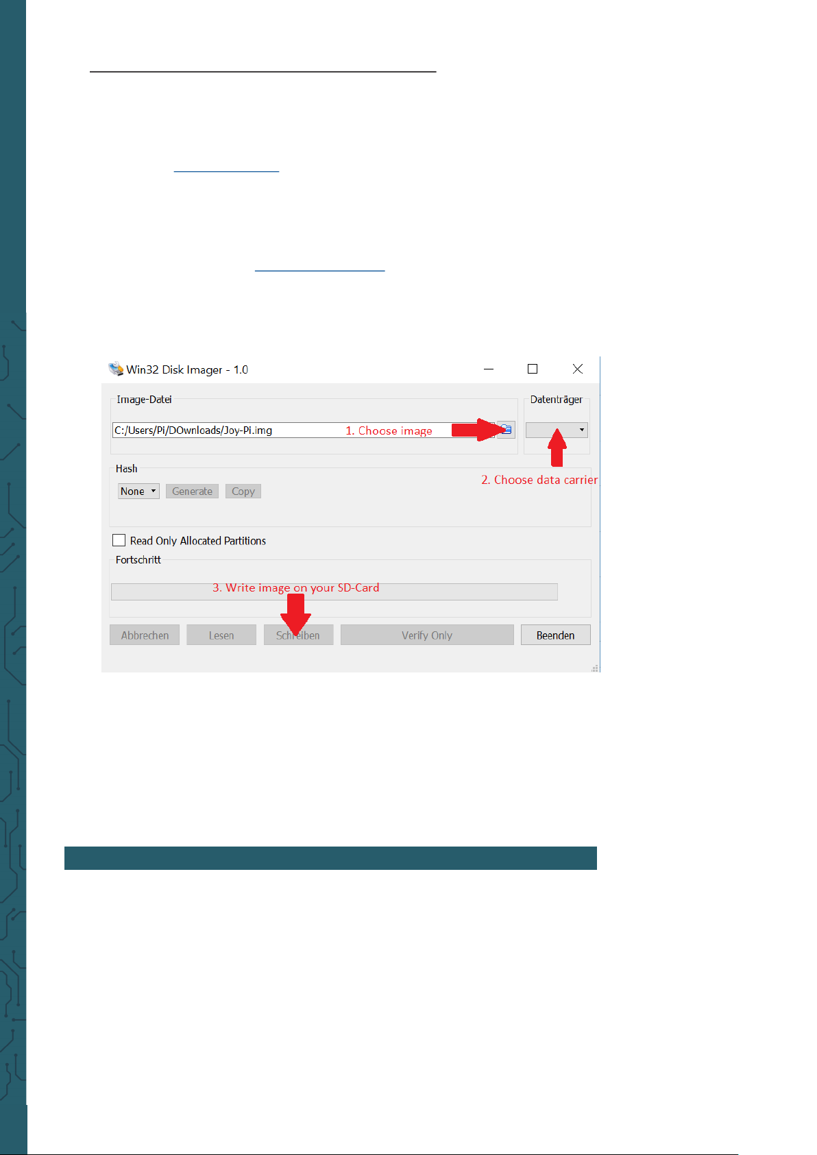
3. Start the program Win32-Disk-Imager and choose
① the downloaded image file.
② the device which is to be written.
4. Now the card is written with the operating system and you can in-
sert it into the microSD card slot of the Raspberry Pi.
5. At the end, you have to edit the image to the size of your SD card.
Therefore, start the Raspberry Pi, open the terminal and enter
sudo raspi-config.
Click now on
Advanced Options
and aer that
Expand Filesystem
.
Aer a restart, the size of the image will be adjusted to your SD
card.
5. USAGE OF PYTHON AND LINUX
This step is optional but it makes it easier to execute scripts without having to create them individually. On the included microSD card are the
scripts already on the desktop.
The scripts which are used in this guide can be downloaded directly from
a package. Therefore, follow the following instructions:

www.joy-it.net
Pascalstr. 8 47506 Neukirchen-Vluyn
1. Open the Terminal. We will need this to perform most of our
Python scripts and to download scripts and expansions.
2. Aer we have successfully opened the terminal, we need to download the script archive to the desktop (included on the image) using
the following command
cd Desktop/
wget https://www.joy-it.net/files/files/Produkte/RB-Joy-Pi/Joy-
3. Press Enter on your keyboard. Now you have to unzip the archive:
unzip Joy-Pi.zip
4. Press Enter again on your keyboard and wait until the process
succeeded.
5. With the command cd, you can change to the right folder to be able
to use the scripts which are placed there:
cd Joy-Pi/Python3
Attention! Every time you shut down your Joy-Pi, you must
repeat these steps to change the folder.
The login data is:
Username : pi
Password : 12345
Performing Python scripts
Aer we successfully downloaded our script, we would like to execute it.
Open the terminal again and follow the instructions below to run the
script:
1. Enter the command sudo python3 <script name> to perform
a Python script like for example:
sudo python3 buzzer.py
This command consist of 3 parts. Because of the command sudo , the following part of the command line will be performed with root right (admin
rights).python3 is the command of the programming language with the
same name, in which the scripts are written in. At the end of the
command, the name of the script is stated. Therefore, you should note
that you must be in the right folder in which the script is saved or the
indicated path (e.g. ~/Joy-Pi/buzzer.py).
www.joy-it.net
Pascalstr. 8 47506 Neukirchen-Vluyn
6. LESSON
Lesson 1 : Using the buzzer for warning sounds
In the previous explanation, we learned how to use the GPIO pin both as
output and input. To test this now, we go ahead with a real example and
apply our knowledge from the previous lesson. The module we will use is
the Buzzer.
We will use the GPIO output to send a signal to the buzzer and to close
the circuit, to generate a loud buzz. Then we will send another signal to
turn it o.
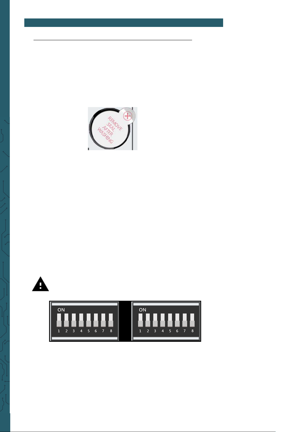
The buzzer is located on the right side of the Joy-Pi-Board and is easily
recognized by the loud noise that it will make when activated. When you
use your Joy-Pi for the first time, the buzzer may have a protective sticker
on it. Make sure this sticker has been removed before using the Buzzer.
Just like in the previous example, we have prepared a special script with
detailed comments that will explain how the whole buzzer process
works, and how we can control the buzzer with the GPIOs.
First, we import the RPi.GPIO library and the time library. Then we
configure the buzzer. At pin 12 we set the GPIO mode to GPIO BOARD and
the pin as OUTPUT.
We output a signal for 0.5 seconds and then turn it o.
Attention! In this example, you have to switch all switches on
the le as well as on the right OFF.
www.joy-it.net
Pascalstr. 8 47506 Neukirchen-Vluyn
#!/usr/bin/python
import RPI.GPIO as GPIO #import the required librarys
import time
buzzer_pin = 12 #define buzzer pin
GPIO.setmode(GPIO.BOARD)
GPIO.setup(buzzer_pin, GPIO.OUT)
GPIO.output(buzzer_pin, GPIO.HIGH) #make buzzer sound
time.sleep(0.5) #wait 0.5 seconds
GPIO.output(buzzer_pin, GPIO.LOW) #stop buzzer sound
GPIO.cleanup()
Execute the following commands and try it yourself:
cd /home/pi/Desktop/Joy-Pi/Python3
sudo python3 buzzer.py
Lesson 2 : Controlling the buzzer with key inputs
Aer successfully demonstrating how to turn the buzzer on and o, it is
time to make things a little more exciting. In this lesson, we will combine
a button with the buzzer so that the buzzer is only turned on by pressing
the button.
This time we will use 2 GPIO setups. One will be the GPIO.INPUT, which
takes the button as an input, another will be the GPIO.OUTPUT, which
sends a signal to the buzzer to output a sound.
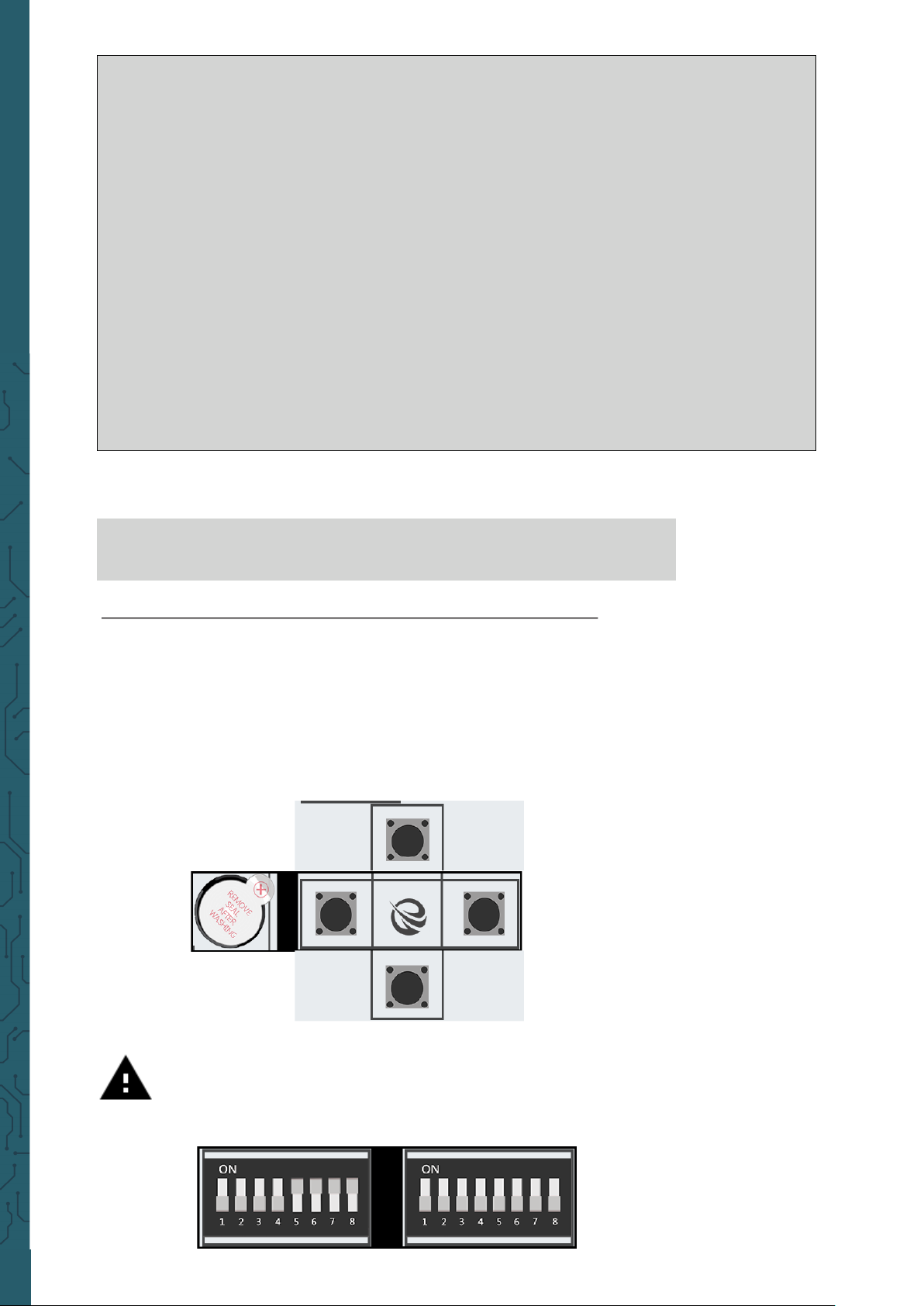
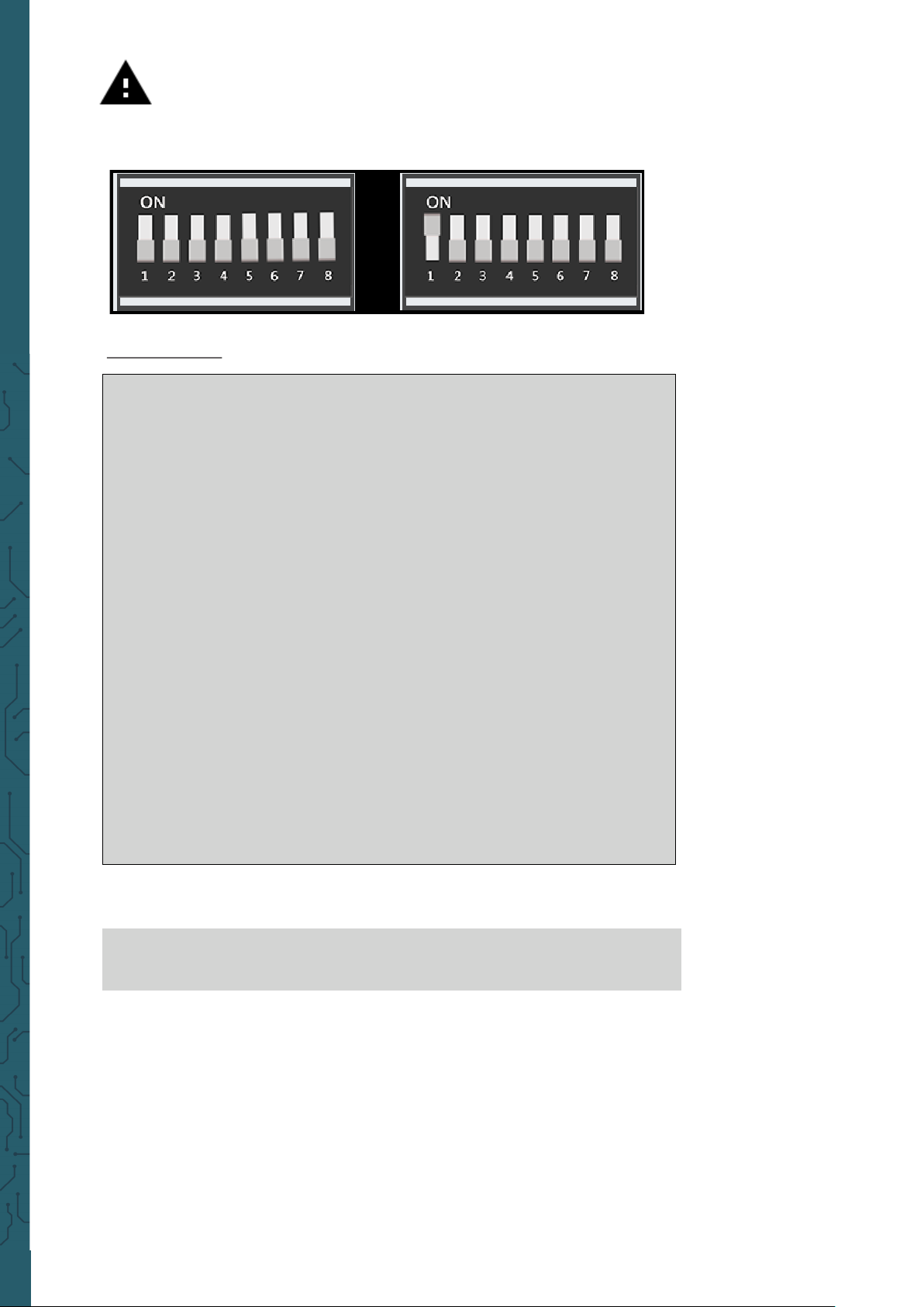
Attention! For this example, you have to switch between the
modules. Turn switch numbers 5, 6, 7 and 8 on the le switching
unit ON. All the other switches should be turned OFF.

www.joy-it.net
Pascalstr. 8 47506 Neukirchen-Vluyn
In our example we use the upper of the 4 keys on the lower le side.
Theoretically, however, any of the 4 keys can be used. If you still want to
use another key, you have to change the pin assignment accordingly.
GPIO37 Upper button
GPIO33 Lower button
GPIO22 Le button
GPIO35 Right button
For this part of our tutorial we need to use 2 GPIO settings. One input and
one output. The GPIO input is used to determine when a key was pressed
and the GPIO output is used to activate the buzzer when that key is
pressed.
If you press the button on your Joy-Pi, the buzzer does a sound! Release
the key and the buzzer will stops. The programm will be performed as
long as CTRL + C is not beeing pressed.
Code example:
#!/usr/bin/python
import RPI.GPIO as GPIO #import necessary libraries
import time
#define pins
button_pin = 37
buzzer_pin = 12
#set board mode to GPIO.BOARD
GPIO.setmode(GPIO.BOARD)
#setup button_pin as input and buzzer_pin as output
GPIO.setup(button_pin, GPIO.IN, pull_up_down=GPIO.PUD_UP)
GPIO.setup(buzzer_pin, GPIO.OUT)
try:
while True:
#check if button pressed
if (GPIO.input(button_pin) == 0):
#set buzzer on
GPIO.output(buzzer_pin, GPIO.LOW)
else:
#button is not pressed, set buzzer off
GPIO.output(buzzer_pin, GPIO.LOW)
except KeyboardInterrupt:
GPIO.cleanup()
www.joy-it.net
Pascalstr. 8 47506 Neukirchen-Vluyn
Execute the following commands and try it yourself:
Lesson 3 : How a relay is working and how to control it
cd /home/pi/Desktop/Joy-Pi/Python3
sudo python3 button_buzzer.py
Now that we know everything we need to know about the buzzer, it is
time for the next lesson. Now we will learn how to use the relay, what the
function of the relay is and how to control it.
Simplified a relay is a switch that can be turned on and o with the help
of GPIO pins. Relays are used to control a circuit through a separate low
power signal or in case that more than circuit must be controlled through
one signal. In our example, we show you how a GPIO signal is sent to
close the relay to activate an individual circuit and how to sent another
signal, to open the relay and to deactivate the circuit.
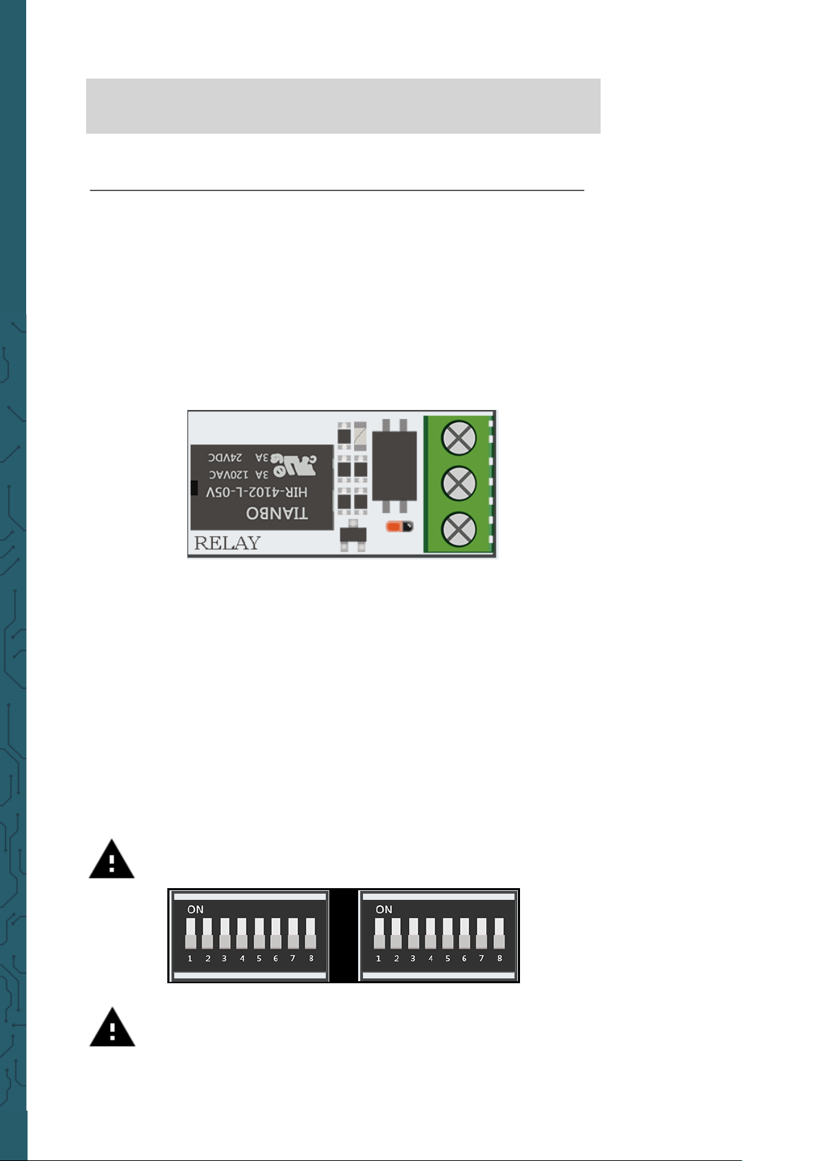
The relay is located in the middle, lower part of the board, next to the key
matrix. It has 3 inputs of which we will use 2 in this example. NC means
normally closed
, NO means
normally open
and COM means
common
.
Common
means, in this case, the common ground.
If a circuit is connected to NC and COM, the circuit is closed if the control
current circuit has not any voltage (GPIO.LOW). If the control current has
a voltage (GPIO.HIGH), the relay opens the connection of the operating
current circuit and the current flow will be stopped
The usage of NO and COM is exactly the opposite. If the control current
circuit has no current (GPIO.LOW), the relay is opened and the operating
current circuit is interrupted. If the control current circuit is supported by
current (GPIO.HIGH), the relay closes the operating current and the current flows.
Attention! In this example you have to switch all switching units
on the le as well as all on the right OFF.
Attention! It is essential that you do not try to connect high
voltage devices to the relay (e.g. table lamp, coee machine,
etc.) This could cause electric shocks and serious injuries.

www.joy-it.net
Pascalstr. 8 47506 Neukirchen-Vluyn
Execute the following commands and try it yourself:
#!/usr/bin/python
import RPI.GPIO as GPIO
import time
#define relay pin
relay_pin = 40
#set GPIO mode as GPIO.BOARD
GPIO.setmode(GPIO.BOARD)
#setup relay_pin as OUTPUT
GPIO.setup(relay_pin, GPIO.OUT)
#open relay
GPIO.output(relay_pin, GPIO.LOW)
#wait haf a second
time.sleep(0.5)
#close relay
GPIO.output(relay_pin, GPIO.HIGH)
GPIO.cleanup()
cd /home/pi/Desktop/Joy-Pi/Python3
sudo python3 relay.py
Lesson 4 : Sending a vibration signal
Have you ever wondered how your phone vibrates when someone calls
you or when you receive a message? We built exactly the same module
into our Joy-Pi and now we will learn how to use it.
The vibration module is located on the right side of the LED matrix and
below the segment LED. If it is on, it is diicult to tell where the vibration
is coming from because it feels like the whole Joy-Pi board is vibrating.
The vibration module uses a GPIO.OUTPUT signal just like the Buzzer and
other modules previously used. If you send an output signal, the module
will start vibrating. If you stop the signal with GPIO.LOW, the
vibration will stop.
You can adjust the vibration length with dierent time.sleep() intervals.
Try it yourself and maybe you can expand this example.
www.joy-it.net
Pascalstr. 8 47506 Neukirchen-Vluyn
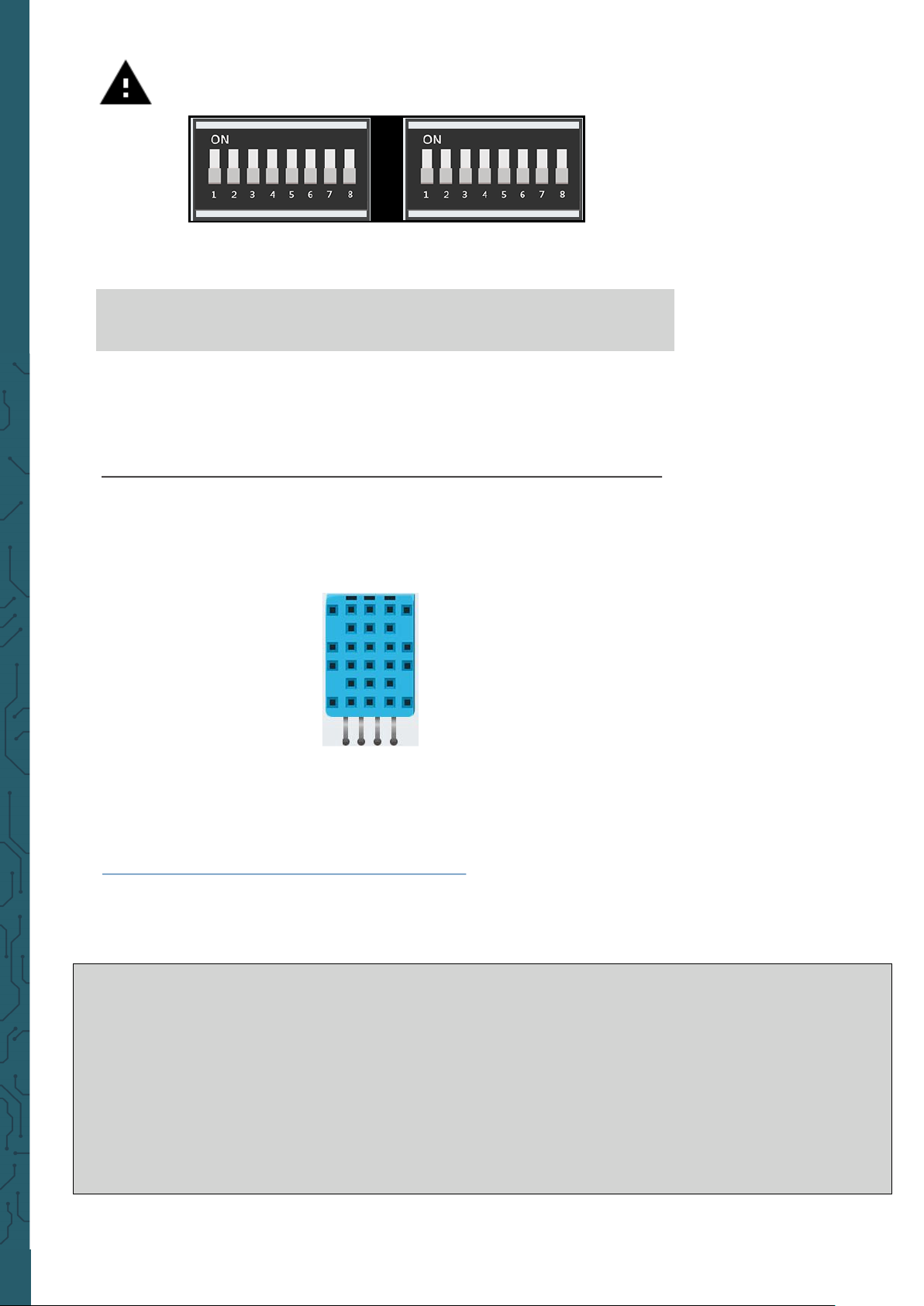
Attention! For this example you have to switch between the
modules. Turn switch number 1 on the right switching unit ON.
All the other switches should be turned OFF.
Code example:
#!/usr/bin/python
import RPI.GPIO as GPIO
import time
#define vibration pin
vibration_pin = 13
#set board mode to GPIO.BOARD
GPIO.setmode(GPIO.BOARD)
#setup vibration pin to OUTPUT
GPIO.setup(vibration_pin, GPIO.OUT)
#turn on vibration
GPIO.output(vibration_pin, GPIO.HIGH)
#wait one second
time.sleep(1)
#clean up GPIO
GPIO.output(vibration_pin, GPIO.LOW)
GPIO.cleanup()
Execute the following commands and try it yourself:
cd /home/pi/Desktop/Joy-Pi/Python3
sudo python3 vibration.py

www.joy-it.net
Pascalstr. 8 47506 Neukirchen-Vluyn
Lesson 5 : Detecting noises with sound sensor
In this lesson, we will learn how to use the sound sensor to make inputs,
detect loud noises and react accordingly. So you can build your own
alarm system that detects loud noises or turn on an LED by clapping!
The sound sensor consists of two parts: a blue potentiometer, which
regulates the sensitivity, and the sensor itself, which detects the input of
sounds. The sound sensor can be easily recognized by the blue
potentiometer and the sensor itself is located on the right under the
buzzer.
With the help of the potentiometer we can regulate the sensitivity of the
sensor. For our script to work, we must first learn how to control the sensitivity. To adjust the sensitivity you have to turn the small screw on the
potentiometer with a screwdriver to the le or right. The best way to test
the sensitivity is to run the script. Clap your hands and see if the device is
receiving a signal. If no signal is received this means that the sensitivity of
the sensor is not set high enough. This can be easily corrected by turning
the potentiometer.
#!/usr/bin/python
import RPI.GPIO as GPIO
import time
#define sound_pin
sound_pin = 18
#set GPIO mode to GPIO.BOARD
GPIO.setmode(GPIO.BOARD)
#setup sound_pin as INPUT
GPIO.setup(sound_pin, GPIO.IN, pull_up_down=GPIO.PUD_UP)
try:
while True:
#check if sound detected or not
if(GPIO.input(sound_pin)==GPIO.LOW):
print(‘Sound detected‘)
time.sleep(0.1)
except KeyboardInterrupt:
#CTRL+C detected, cleanning and quitting the script
GPIO.cleanup()

www.joy-it.net
Pascalstr. 8 47506 Neukirchen-Vluyn
First, we define our pin GPIO 18. Aerwards, we set a while loop to run
this script permanently. We check if we have received an input from the
sound sensor indicating that loud noises have been detected and then
we print
Sound detected
.
If you press CTRL + C, the programm will be closed.
Execute the following commands and try it yourself:
cd /home/pi/Desktop/Joy-Pi/Python3
sudo python3 sound.py
Attention! In this example you have to switch all switching units
on the le as well as all on the right OFF.
Lesson 6 : Detecting brightness with the light sensor
The light sensor is one of our favorites. It is extremely useful in many
projects and situations, e.g. with lamps that switch on automatically as
soon as it gets dark. With the light sensor we can see how bright the
module surface is.
The light sensor is diicult to detect because it consists of very small
parts. The sensor is to the le of the buzzer. If you cover it with your
finger, the output of the light sensor should be close to zero, as no light
can reach it.
It is time to test it in real time and see how it works. However, the light
sensor is a little dierent from other sensors because it works with I2C
and not with the normal GPIOs as we learned in the lessons before.
In this script we use a function to communicate with the sensor, this way
we can get the wished output with the brightness. The higher the displayed number, the brighter is the surrounding.

www.joy-it.net
Pascalstr. 8 47506 Neukirchen-Vluyn
#!/usr/bin/python
# -*- coding: utf-8 -*-
# Author: Matt Hawkins
# Author's Git: https://bitbucket.org/MattHawkinsUK/
# Author's website: https://www.raspberrypi-spy.co.uk
import RPi.GPIO as GPIO
import smbus
import time
if(GPIO.RPI_REVISION == 1):
bus = smbus.SMBus(0)
else:
bus = smbus.SMBus(1)
class LightSensor():
def __init__(self):
#define some constants from the datasheet
self.DEVICE = 0x5c #default device I2C address
self.POWER_DOWN = 0x00 #no active state
self.POWER_ON = 0x01 #power on
self.RESET = 0x07 #reset data register value
#start measurement at 4 Lux
self.CONTINUOUS_LOW_RES_MODE = 0x13
#start measurement at 1 Lux
self.CONTINUOUS_HIGH_RES_MODE_1 = 0x10
#start measurement at 0.5 Lux
self.CONTINUOUS_HIGH_RES_MODE_2 = 0x11
#start measurement at 1 Lux
#device is automatically set to power down mode after measurement
self.ONE_TIME_HIGH_RES_MODE_1 = 0x20
#start measurement at 0.5 Lux
#device is automatically set to power down mode after measurement
self.ONE_TIME_HIGH_RES_MODE_2 = 0x21
#start measurement at 4 Lux
#device is automatically set to power down mode after measurement
self.ONE_TIME_LOW_RES_MODE = 0x23
def convertToNumber(self, data):
#Simple function to convert 2 Bytes of data
#into a decimal number
return ((data[1] + (256 * data[0])) / 1.2)
def readLight(self):
data = bus.read_i2c_block_data(self.DEVICE,self.ONE_TIME_HIGH_RES_MODE_1)
return self.convertToNumber(data)
def main():
sensor = LightSensor()
try:
while True:
print("Light Level : " + str(sensor.readLight()) + " lx")
time.sleep(0.5)
except KeyboardInterrupt:
pass
if __name__ == "__main__":
main()
www.joy-it.net
Pascalstr. 8 47506 Neukirchen-Vluyn
Attention! In this example you have to switch all switching units
on the le as well as all on the right OFF.
Lesson 7 : Detecting the temperature and the humidity
The DHT11 sensor is very easy to recognize. A small blue sensor with
many small holes. It is located to the right of the relay and above the
touch sensor. As specially accessible, we recommend the Python DHT
Sensor Library which was published on
https://github.com/coding-world/Python_DHT .
The library is used to display the values for the temperature and humidity
without the need of any complicated mathematical calculations.
Execute the following commands and try it yourself:
cd /home/pi/Desktop/Joy-Pi/Python3
sudo python3 light_sensor.py
The DHT11 is a very interesting sensor, because it has not only one
function, but two! It contains both a humidity sensor and a temperature
sensor, both of which are very accurate. Ideal for any weather station
project, or if you want to check the temperature and humidity in the
room!
import Python_DHT #import of the library
sensor = Python_DHT.DHT11 #sensor is defined
pin = 4 #pin of DHT11 is defined
#Reading out the values
feuchtigkeit, temperatur = Python_DHT.read_retry(sensor, pin)
#Output of the values
print("Temperature = "+str(temperatur)+ "C Humidity = "+str( feuchtigkeit)+"%")
www.joy-it.net
Pascalstr. 8 47506 Neukirchen-Vluyn
Attention! In this example you have to switch all switching units
on the le as well as all on the right OFF.
Execute the following commands and try it yourself:
cd /home/pi/Desktop/Joy-Pi/Python3
sudo python3 dht11.py
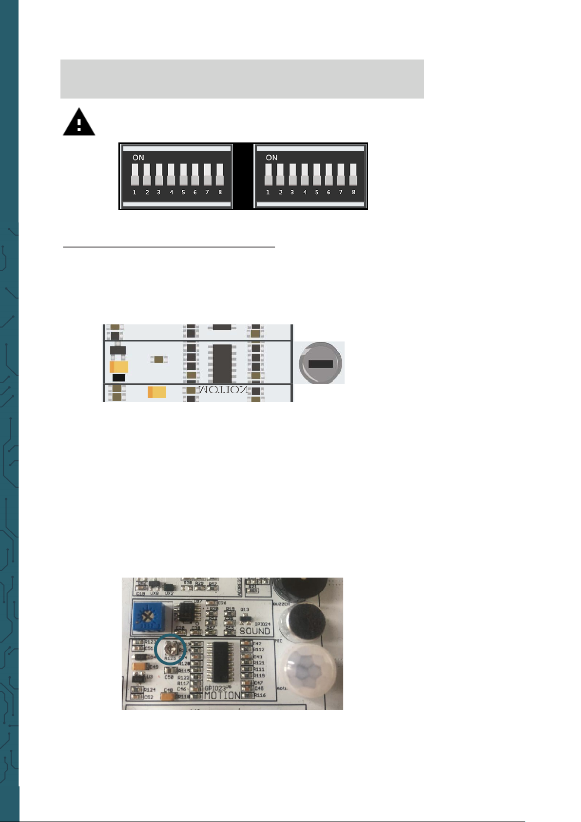
Lesson 8 : Detecting movements
The motion sensor is one of the most useful and frequently used sensors.
It can be used, for example, to build an alarm system. When the sensor
detects a movement, it can send a signal to the buzzer, which then makes
a loud alarm.
The motion sensor is located directly under the sound sensor and is
covered by a small, transparent cap. The cap helps the sensor to detect
more movements by refracting the infrared light of the environment. The
sensitivity of the motion sensor, like that of the sound sensor, is controlled with a potentiometer. This is located below the potentiometer of
the sound sensor, but is much smaller. By using a screwdriver, you can
set the distances, over which the motion sensor should react. By turning
it clockwise the sensitivity decreases and counter-clockwise it increases.
The motion sensor is controlled by the GPIO pins. When a motion is
detected, the motion sensor will send a signal. This will stop for some
time and then start again until the sensor detects the next movement.
 Loading...