

Page 1
Beginner’s Guide
to the
PI LCD
Part 1: Assembly
W8BH
1) INTRODUCTION
LCD Modules are a very common and inexpensive interface for microcontroller boards like
the Arduino. So why would you want to connect one to the Raspberry Pi, which has
advanced, high-resolution video display capability?
- Your HDMI display is hooked up to your other Raspberry Pi
- Your HDMI display is actually your TV, and someone is using it.
- You don’t have a video display device for your Pi.
- You want to learn about LCD modules.
- Because you can.
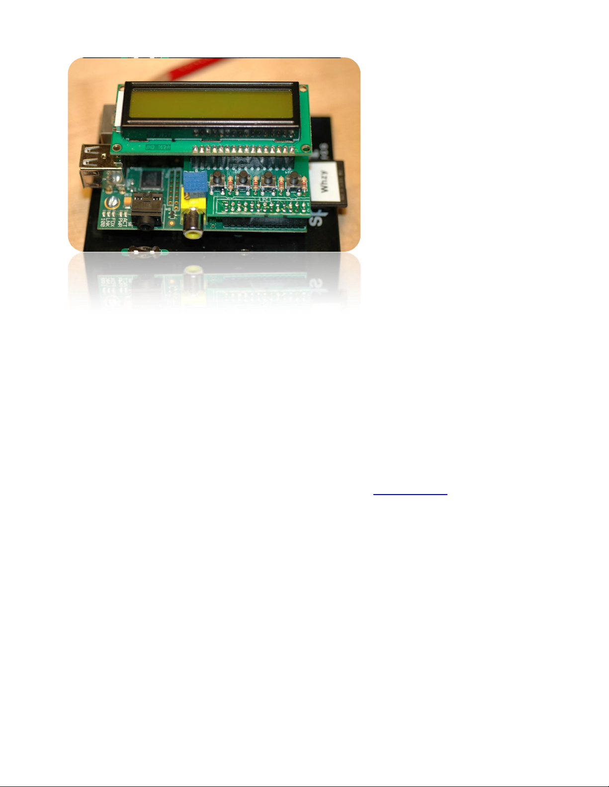
In this tutorial we will look at the handy LCD module sold at mypishop.com. It mounts on
top of your pi, and gives us four pushbutton switches in addition to a choice of LCD modules
to use.
2) ASSEMBLY
Building this small board is very straightforward. There are very few parts: four switches,
four resistors, a 26-pin female header, a row of male header pins, and the LCD. As always,
put them in some container on your workspace so they don’t walk away. I use a shoebox
lid.
There are no directions for the kit, so print out the online assembly instructions. All of the
parts, EXCEPT the 26-pin header, go on the printed side of the board.
Did you notice an adhesive-backed plastic disc in your kit? This disc provides physical and
electrical isolation between your add-on board and the Pi. It also provides for some
Page 2
mechanical stability. Mount your board on the Pi and press down on it. The first thing my
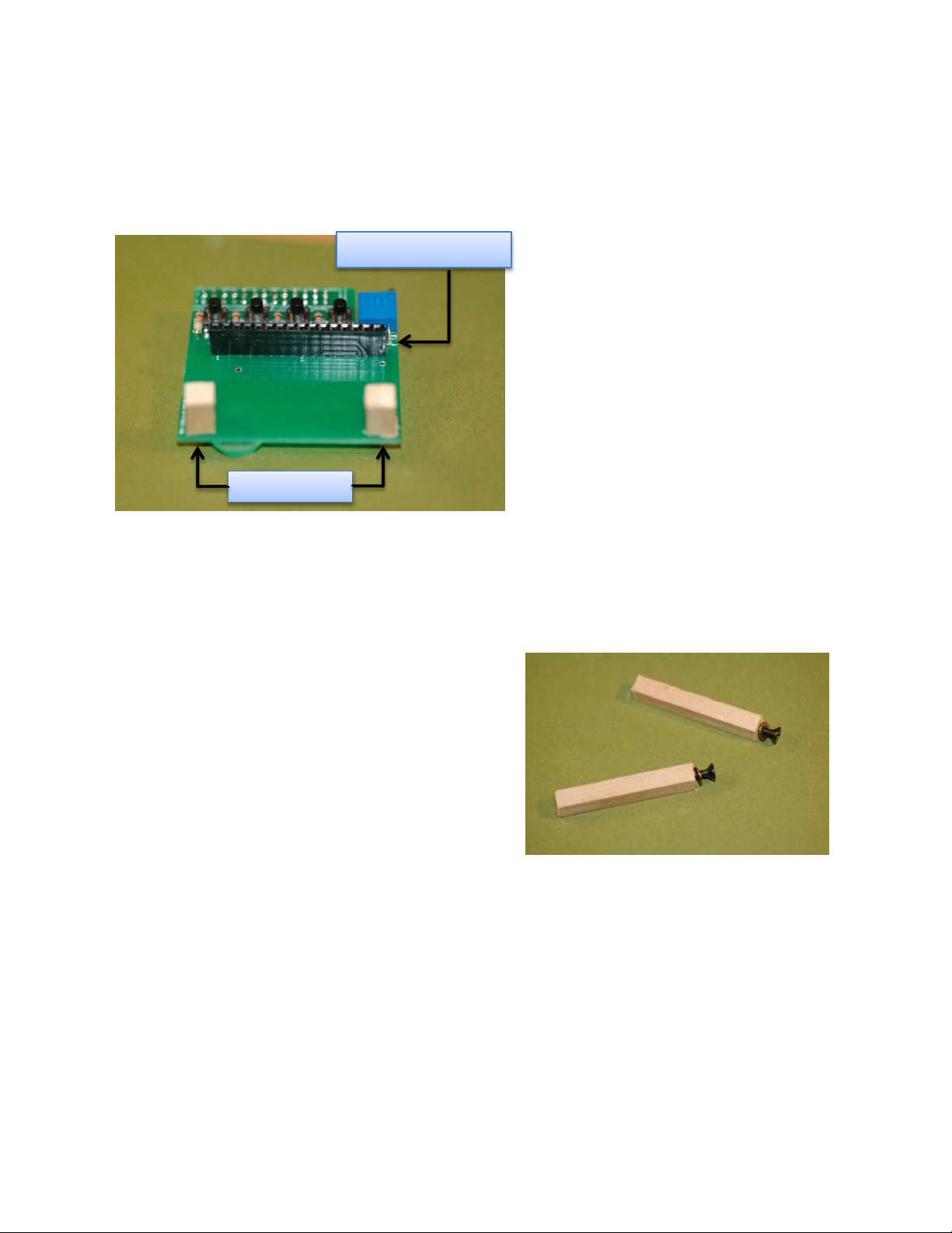
16-pin female header
Support Posts
board hits is a tall electrolytic capacitor on the Pi. Put your adhesive disc at this spot. You
can affix the disc to the bottom of the board or to the top of the capacitor. Either way, it
prevents direct contact and minimizes board sagging.
Here is a photo of my board. I decided
NOT to solder the LCD to the board.
Instead I soldered a 16-pin female
header. The header will let you plug in
different LCDs. I have put 16x2 and
20x4 displays on my board, and this
small modification lets me try whatever
LCD I like. Most backlit LCD modules
use the same industry-standard 16-pin
configuration, and will be compatible
with your board.
If you use a 20x4 display, you may
notice how heavy the display is. It also
can cause the board to sag, and put strain on the 26-pin connector. If you use a female
header like me, the sagging and strain will be even more obvious. What can you do?
3) BE SUPPORTIVE
If a sagging display bothers you, just prop it up!
This is surprisingly easy to do. Visit your local
hobby store/Home Depot/Lowes and get some
basswood/balsa strips. You will only need a few
inches, so one strip will do. Mine are about ¼”
square, and make excellent support posts. Hold
the strip beside your mounted display, and pencil-
mark it for the length you need. It doesn’t hurt to
add 1/16” or so, since the post can be shortened
very quickly. Cut two lengths. Drill a small 1/16”
pilot hole on the top of each post. Attach the post
to your LCD using a #4 wood screw. If a post is too long, sand it down. If too short, add
one or two #4 washers between the post and display (or cut another post - it won’t take
long).
You don’t have to use wood. You can do the same thing with nylon standoffs, metal or
acrylic rod. But wood is easy to use, cheap, and doesn’t need to be tapped. Be creative.
If you install a female header like I did, then drill two 1/8” holes along the bottom edge of the
board and attach two small posts. These posts will give you plenty of support to whatever
LCD module you attach.
Page 3

4) SMOKE TEST
Your Pi should be turned off when your mount your board. Check all your solder joints.
Then mount the board onto the Pi’s GPIO pins. Don’t be a dimwit like me and mount your
display backwards -- it won’t work. The board mounts over the Pi, not away from it.
Check to see that the connector is correctly seated on the pins, and turn on the power.
The backlight on your LCD display should immediately light up, telling you that it has power.
If not, immediately unplug and check everything again.
Next, adjust the display contrast, until you see a strip of rectangles across the display.
Don’t skip this step: many folks have checked and rechecked their code for errors, only to
find out later that the code was fine but the display was turned all the way down. Use a
small screwdriver to turn the shaft of the potentiometer. Don’t tickle the dragon’s tail - a slip
of the screwdriver can ruin your whole day. Keep the metal screwdriver tip away from your
Pi. I put a piece of paper over the Pi while adjusting the contrast.
5) BABY STEPS
Once your display is adjusted, it’s time for some programming! But pumping out characters
to our display is not so easy: each character must be broken into two halves, sent to the
display, and clocked in with additional signal that has specific timing requirements. I tried
to do all of this on my first attempt, and of course it didn’t work. Let’s start smaller, and
work our way up.
Fortunately, our board also comes with something much less complicated: switches. We
will get them working first, and then go to the LCD.
One leg of each push-button switch goes to ground through a 1K resistor. The other side of
the switch goes to a GPIO pin. Push a switch, and the GPIO line will be grounded (logic 0).
We have four switches, each attached to a GPIO pin. We will start with GPIO9, which is
attached to the switch closest to the left edge of the board.
There are two popular Python modules for GPIO programming: RPi.GPIO and WiringPi. I
downloaded and installed both. WiringPi has the current advantage of a companion LCD
module - relieving you of learning about LCD programming! WiringPi also has a familiar
feel to anyone used to Arduino coding. But I am going to skip over it, and write about
RPi.GPIO instead. Try both and see which one you prefer.
If you are using a recent version of Raspian on your Pi, then you already have RPi.GPIO
installed. If not, visit the project home page at http://code.google.com/p/raspberry-gpio-
python/ to get the latest version.
Let’s start with the interactive-mode python interpreter. RPi.GPIO must run from root, so
please login as root and start python. You will see the triple-chevron (>>>) prompt:
$ su
# python
>>>
Page 4

Import the RPi.GPIO module. The first thing we’ll do is configure it to use the Broadcom
port-numbering scheme. And we’ll turn off warnings about port usage:
>>> import RPi.GPIO as GPIO
>>> GPIO.setmode(GPIO.BCM)
>>> GPIO.setwarnings(False)
If python complains at the first statement, make sure that: 1) you have already installed
RPi.GPIO; 2) you spelled it correctly, with a lower-case ‘i’; and 3) you started python from
root.
Now we are ready to specify which I/O pins we are going to use, and how we are going to
use them. Remember, we are going to use GPIO9, which is attached to the leftmost switch.
We must declare it as an input. And we need to enable the built-in pullup resistor. Without
a pullup, floating (unconnected) inputs have random, unpredictable logic values. Pullup
resistors make sure that, in the absence of any electrical input, the input value will be logic
1. All of the above conditions are accomplished by a single python statement:
>>> GPIO.setup (9, GPIO.IN, pull_up_down=GPIO.PUD_UP)
Assuming that you got no feedback from the four python statements above, input on GPIO9
is ready. Lets see what value we get. Remember that the internal pullup keeps the line at
logic 1:
>>> GPIO.input(9)
True
Try it again, this time while pressing down on the push-button. The closed switch should
pull the input line to logic 0:
>>> GPIO.input(9)
False
If you got these results, everything is working fine. Type exit() to leave python. It’s time to
write a real program.
6) WRITING THE CODE
First, lump all of the GPIO setup statements into a single function:
def InitIO ():
GPIO.setmode(GPIO.BCM)
GPIO.setwarnings(False)
GPIO.setup(4, GPIO.IN, pull_up_down=GPIO.PUD_UP)
GPIO.setup(23, GPIO.IN, pull_up_down=GPIO.PUD_UP)
GPIO.setup(10, GPIO.IN, pull_up_down=GPIO.PUD_UP)
GPIO.setup(9, GPIO.IN, pull_up_down=GPIO.PUD_UP)
Page 5

You can write each setup statement, or create a loop to do all four. Next, add a routine that
checks each input and writes its value to the console:
def CheckSwitch ():
val1 = not GPIO.input(4)
val2 = not GPIO.input(23)
val3 = not GPIO.input(10)
val4 = not GPIO.input(9)
print val1,val2,val3,val4
I added the ‘not’ operation so that push-button presses show up as ‘True’, rather than
‘False’. Finally, re-check once per second, until the user (you) are satisfied with the result:
while (True):
CheckSwitch()
time.sleep(1)
Run it, and try pressing any combination of pushbuttons. Hit Ctrl-C when you are satisfied
each input is working correctly.
That’s all for now. In Part 2 of this series we will display data on the LCD.
Page 6

6) PYTHON SCRIPT for PI LCD, PART 1:
########################################################################
#
# LCD1.py: Learning how to read GPIO inputs
#
#
#
#
#
########################################################################
import time #for timing delays
import RPi.GPIO as GPIO
#INPUTS: map GPIO to Switches
SW1 = 4 #GPIO4 = Pi pin 7
SW2 = 23 #GPIO16 = Pi pin 16
SW3 = 10 #GPIO10 = Pi pin 19
SW4 = 9 #GPIO9 = Pi pin 21
INPUTS = [SW1,SW2,SW3,SW4]
def InitIO():
GPIO.setmode(GPIO.BCM)
GPIO.setwarnings(False)
for switch in INPUTS:
GPIO.setup(switch, GPIO.IN, pull_up_down=GPIO.PUD_UP)
def CheckSwitches():
val1 = not GPIO.input(SW1)
val2 = not GPIO.input(SW2)
val3 = not GPIO.input(SW3)
val4 = not GPIO.input(SW4)
print val4,val1,val2,val3
#
# Main Program here.
#
print "Pi LCD1 test program starting"
InitIO()
while (True):
CheckSwitches()
time.sleep(1)
 Loading...