

JT-DPH5005
Programmable power supply
1. GENERAL INFORMATION
Dear customer,
thank you for purchasing our product. In the following, we will show you
how to use your product.
Should you encounter any unexpected problems during use, please do not
hesitate to contact us.
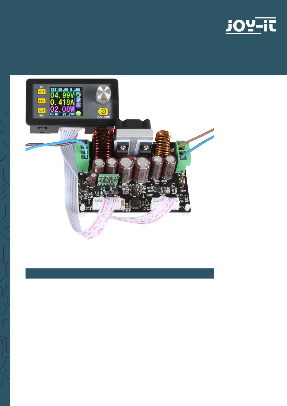
With the DPH5005, voltages can be converted both up and down.
This power supply combines analog and digital technologies in an
advanced design with outstanding precision and accuracy. The adjustable
output reaches up to 50V or 5A and can be precisely congured in 10mV or
1mA steps.
The power supply unit is additionally equipped with a switch-o parameter
memory and ten programmable data memories. The operation of the unit
has been optimized for particularly easy operation and the colour display
oers particularly detailed and comprehensive information. Among other
things, the current voltage and current values, presettings and output
powers can be displayed here. Dynamic notication symbols also facilitate
clarity.
The additional settings menu oers maximum control of overcurrent
and overvoltage values as well as other parameters. The DPH5005 oers
modern design and advanced technology in a compact package, making it
the ideal power supply.
2. TECHNICAL DETAILS
input voltage
output voltage
output current
output power
display size
display module size
power module size
voltage resolution
current resolution
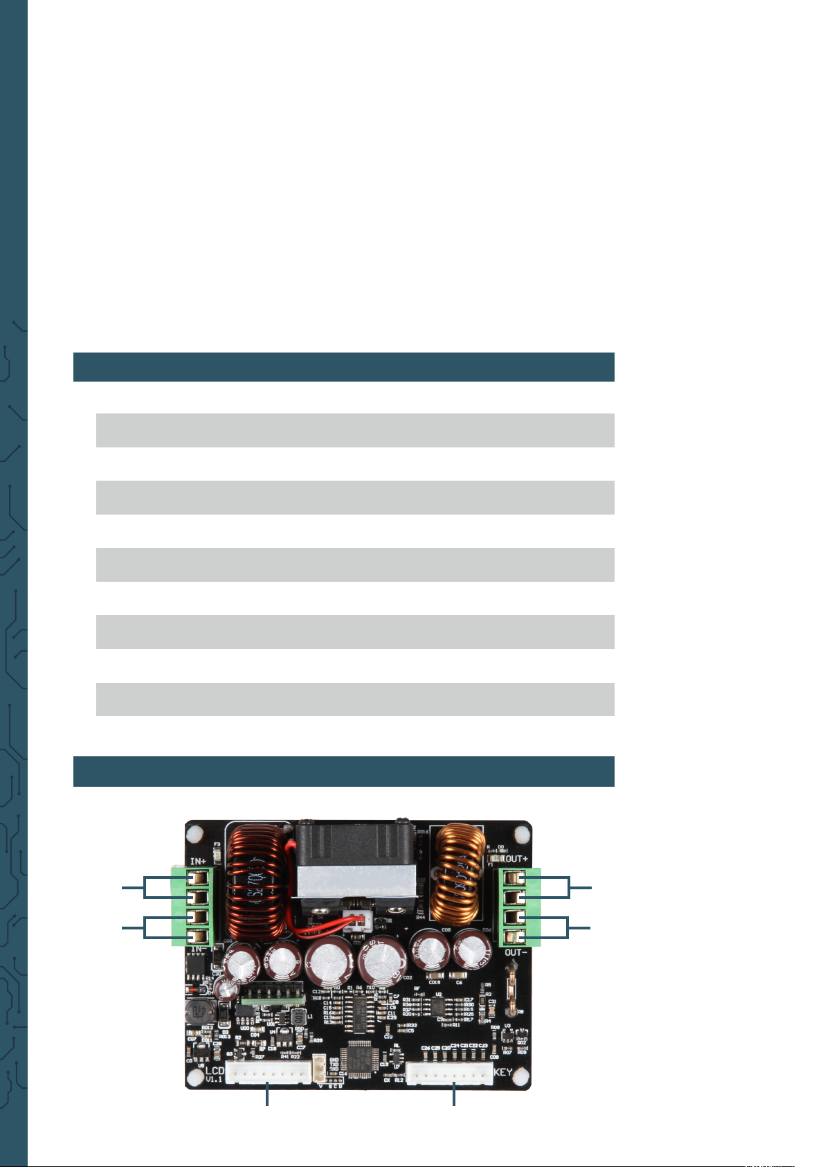
3. CONNECTION DETAILS
6 - 50 V
0 - 50 V
0 - 5 A
0 - 250 W
1.5“
43 x 79 x 38 mm
93 x 35 x 72 mm
0.01 V
0.001 A
pos.
Input +
neg.
Input -
pos.
Output +
neg.
Output -
LCD port KEY port
Attention! Ensure at all times a suicient ventilation of the
device for the heat dissipation.
The permitted output voltage range is between 6 to 50 V
(DC). Watch at the suicient safety distance and do not ever
exceed the maximal output voltage range. Non-observance can
cause substantial and irrparable damage of your device.
Operate the device only with direct current! The operating of
the device with alternating current can cause deadly electric
shocks and irreparable damages to the device.
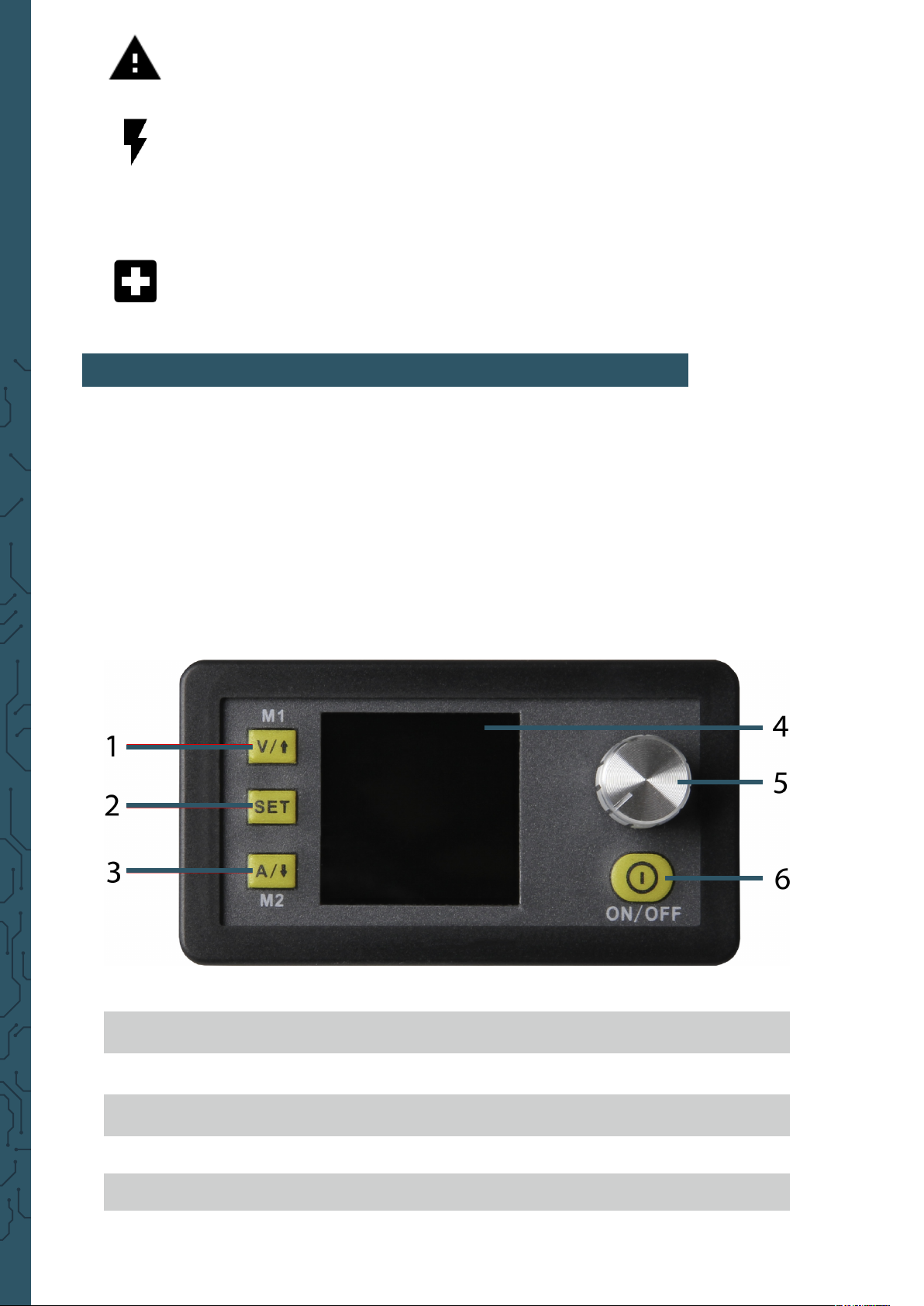
4. PANEL & DISPLAY
Aer the rst start, the welcome screen followed by the main screen are
shown. On the main screen, the selected voltage and current values are
displayed. If the outputs are activated, the actual values are additionally
shown. On the right side of the display are symbols and prompts which
represent the status of the system. A detailed description of the screen is in
the following:
voltage settings / arrow up /
1
2
3
4
5
6
data input / extract data from data group /
current settings / arrow down /
activate / deactivate output
M1 data group
save data in data group
M2 data group
1.5“ LCD display
rotary switch / key lock

main menu settings
7
8
9
10
11
12
13
14
15
16
17
18
19
output volatge (default)
output voltage (current value)
output current (current value)
output power (current value)
input voltage
limit of ouput current
lock / unlock keys
normal/ abnormal status
constant voltage / constant current
number of data group
ouput active / inavctive
default ouput voltage
default limit of ouput current
20
21
22
23
24
25
default overvoltage range
default overcurrent limit
default overload limit
default screen brightness
default number of data group
actual value of output voltage and current

5.USE OF THE DEVICE
Output voltage and current limit
Press V/↑ to open the voltage setting mode. Press the rotary switch to set
the cursor on the numerical value which should be changed. Rotate the
rotary switch clockwise to increase the value and counter clockwise to
decrease the value. Press again V/↑ to end. Alternatively, aer 30 seconds
of being inactive the setting mode ends automatically. Press A/↓ to set the
output current limit the same ways as before.
Conguration of data and conservation values
Press SET in the main screen to open the data settings menu.
Setting the voltage and current limit values
Navigate through the menu to option U-SET (voltage limit) or I-SET (current
limit). Adjust here the output voltage and / or the output current limit aer
your preferences. With SET can you go back to the menu options. Press SET
again to return to the main screen and to leave the menu.
Setting the conservation value
Navigate through the menu to limit value options S-OVP (overvoltage
protection), S-OCP (overcurrent protection) or S-OPP (overpower
protection). Adjust now with the rotary switch the desired value. Press
SET to return to the menu options and again to leave the menu. If the limit
values are reached, the output will be deactivated automatically.
Attention! These are global limit values and should not be
confused with the default voltages and currents.
Adjustment of screen brightness
Navigate to the option B-LED to congurate the screen brightness. Rotate
the rotary switch to adjust the brightness from level 0 to 5. 0 denes the
darkest level and 5 the brightest. Press SET to return to the menu and press
it again to leave the menu.

Conguration of the data groups
Data group M0
The data group M0 is a special case. It is the standard data group. Every
time an alternative data group is chosen or changes at the current settings
are made, the M0 is immediately overwritten by the new data. M0 is
therefore a realtime duplicate of the current chosen data group and the
values. It is also the set of data which is saved by switching o and will
be invoked by starting the device again. This happens automatically and
transparently without any input of the user.
Selection of the processing data group
Navigate to option M-PRE to edit a data group. Rotate the rotary switch
to choose the number of the data group which should be edited. Aer
nishing the settings hold down SET until the number of the data group is
shown on the right side of the screen. By pressing again SET, you leave the
data group settings.
Activation / deactivation
Navigate to option M-PRE and press the rotary switch. Aer that rotate that
switch to choose the data group by its number which should be edited.
Press it again to change the option M-PRE.
By activating this option, the output stays the same by invoking a data
group.
By deactivating this option, the output is automatically switched o by
invoking a data group.
Hold down SET until the number of the data group is shown on the right
side of the screen. The data value will be saved under the number of the
data group. Press again SET to return to the menu. To leave this menu press
SET.
Datagroup quick selection
Key combination by choosing M1 / M2
Hold down V/↑ or A/↓ for longer than 3 seconds to select the data group
M1 or M2 quickly. The number in accordance with the data group is shown
on the right side of the screen. The data group M1 and M2 are perfect for
frequently used settings because of their quick selection function.
Selection of an arbitrary data group
Hold down SET for more than 3 seconds to show M0 on the right side of
the screen. Through rotating the rotary switch is it possible to choose the
desired data group (M0 - M9). To activate the chosen data group, press SET.

Editing the chosen data group
To edit the chosen data group press V/↑ or A/↓ to navigate upwards or
downwards through the menu options. Press the rotary switch and the
according numerical value will be highlighted with the cursor. Further
operation of the knob scrolls through the available characters. Aer the
desired value is set, hold down SET until the data group number is shown
on the right side of the screen. The value of the data will now be saved
in the selected data group. Press the Set button again to return to the
previous menu. Repeat the above procedure to change one of the other
numerical values for the selected data group. To exit the menu, press the
Set button again.
Condition of selected data group at the start
You can congure the device that the output activates automatically as
soon as the device is started. Navigate in the menu to option S-INI and set
the value to ON to activate this option. Aer you set the desired settings,
hold down SET until the number of the data group is shown on the right
side of the screen. The data value is now saved. By pressing SET you return
to the menu and you leave the menu by pressing it again.
Activation and deactivation of the output
You can press the ON/OFF button at any time to activate or deactivate the
output.
Key lock
The keys can be deactivated to avoid unintentional changes. Hold the
rotary switch longer than 3 seconds to block the keys or to unlock them
again. The status of the key lock is shown with the lock symbol on the right
side of the screen.

6. OTHER INFORMATION
Our information and take-back obligations according to the Electrical and Electronic
Equipment Act (ElektroG) Symbol on electrical and electronic equipment:
Symbol of electrical and electronic devices:
This crossed-out dustbin means that electrical and electronic appliances do
not belong in the household waste. You must return the old appliances to
a collec-tion point. Before handing over waste batteries and accumulators
that are not enclosed by waste equipment must be separated from it.
Return options:
As an end user, you can return your old device (which essentially performs
the same function as the new device purchased from us) for disposal free
of charge when you purchase a new device. Small appliances with no external dimensions greater than 25 cm can be disposed of in normal household
quantities independently of the purchase of a new appliance.
Possibility of return at our company location during opening hours:
Simac GmbH, Pascalstr. 8, D-47506 Neukirchen-Vluyn
Possibility of return in your area:
We will send you a parcel stamp with which you can return the device to
us free of charge. Please contact us by e-mail at Service@joy-it.net or by
telephone.
2
Informationen on packaging:
Please pack your old appliance safely for transport, if you do not have
suitable packaging material or do not wish to use your own, please contact
us and we will send you suitable packaging.
7. SUPPORT
If any questions remain open or problems arise aer your purchase, we are
available by e-mail, telephone and ticket support system to answer these.
E-Mail: service@joy-it.net
Ticket-System: http://support.joy-it.net
Telephone: +49 (0)2845 98469 – 66 (10 - 17 o‘clock)
1
For further information visit our website:
www.joy-it.net
Published: 01.08.2019
Simac Electronics Handel GmbH
Pascalstr. 8 47506 Neukirchen-Vluyn
www.joy-it.net
 Loading...