


LABORATORY POWER SUPPLY
JT-RD6012-C
1. GENERAL INFORMATION
Dear customer,
thank you very much for choosing our product.
In the following, we will introduce you to what to observe while starting
up and using this product.
Should you encounter any unexpected problems during use, please do
not hesitate to contact us.
The RD6012-C is a laboratory power supply that can be used in various
operating modes (e.g. constant current or constant voltage operation,
etc.). A keypad and a push and turn encoder make the operation of the
power supply very comfortable. Furthermore, the keypad allows you to
conveniently save and reload up to nine settings. The high-resolution 2.4inch color display clearly shows all the important information. The USB
interface and an optional Wifi interface allow you to operate the device
via PC or with an app from mobile devices.
Pascalstr. 8 47506 Neukirchen-Vluyn
www.joy-it.net

2. TECHNICAL SPECIFICATIONS
Display 2.4 " colour LCD
Input voltage range 230 V AC
Output voltage range 0 - 60 V DC
Output current range 0 - 12 A
Output power range 0 - 720 W
Input voltage accuracy ± 1 % + 5 digits
Output voltage accuracy ± 0,3 % + 3 digits
Output current accuracy ± 0,5% + 5 digits
Battery voltage measurement accuracy ± 0,5% + 3 digits
Input voltage measurement resolution 0,01 V
Output voltage measurement resolution 0,01 V
Current setting measurement resolution 0,01 A
Battery voltage measurement resolution 0,01 V
Constant voltage mode response time 2 ms at 0,1 - 5 A load
Constant voltage mode load regulation ± 0,1 % + 2 digits
Constant current mode load regulation ± 0,1 % + 3 digits
Capacity measurement range 0 - 9999,99 Ah
Energy measurement range 0 - 9999,99 Wh
Capacity and Energy statistical error ± 2 %
Output ripple typ. 100mV VPP
Sensor temperature detection range -10 - 100°C / 0- 200 ° F
Sensor temperature detection accuracy ± 3° C / ± 6 °F
Working mode step down (buck) mode
Voltage drop min. 1V and min. 10 %
Screen brightness setting Level 0 - 5, 6 levels total
Working temperature range - 10° - 40 ° C
3. SCREEN OVERVIEW
Button lock status
Button tune
Communication Interface
Time
Current output voltage
Current output current
Current output power
Current data group
Constant voltage/Constant current status
Protection status indication
Input voltage
Output voltage preset value
Output current preset value
Overvoltage protection value
Overcurrent protection value
Battery-related information
Battery charging indication
www.joy-it.net
Pascalstr. 8 47506 Neukirchen-Vluyn

4. DEVICE OVERVIEW
4.1. Front Panel
Rotary Encoder
Direction buttons
Confirm button
Keypad
Screen
Output switch
Power supply output
positive terminal
Power button
Second function button
Quick storage button
Current /Overcurrent protection
value setting
4.2. Back Panel
Voltage/ Overvoltage
protection value setting
Micro USB Interface
Power Source input interface
Input fuse External temperature sensor interface
Battery charging
positive terminal
Power supply output/
battery charging: negative terminal
CR1220 battery socket
Output fuse
Communication module interface
Fan interface
www.joy-it.net
Pascalstr. 8 47506 Neukirchen-Vluyn

4.3. Case Back Panel
Main on / o
switch
Temperature sensor
socket
Ventilation openings
(do not cover)
Mains socket
(230 V AC @ 50 Hz)
Pascalstr. 8 47506 Neukirchen-Vluyn
www.joy-it.net
5. MENU INTRODUCTION
1. Operation Menu
Press 'SHIFT'+'0' to enter the system setting menu . In the menu operation, the icon
in red or cursor is the currently selected menu; the icon in blue is the unselected
menu; press ENTER to confirm; press the encoder to cancel or return; press the direction key to move the cursor or switch menu; rotate the encoder to change the setting;
the settings will be automatically saved when returning from the menu page.
Press and hold the 0 button and power on to restore the factory settings; press and
hold the 1 button and power on to restore the factory calibration value; press and
hold ENTER and power on to enter the boot mode.
2. Battery Charging mode
The RD6006 and RD6012 have their own battery charging function to facilitate the
charging of batteries and accumulators. To do so, close the negative pole of the battery with the black port and the positive pole with the green port. The battery charging function can detect when a battery is connected by changing the battery symbol
on the display from blue to red. You have to set the charging end voltage and charging current using "I-SET" and "V-SET". You can start and stop charging with ON/
OFF. IMPORTANT! You have to do this according to your battery otherwise there
is danger to life! As a safety measure you can use the temperature sensor of the
power supply unit to observe the behaviour of the battery. With the temperature sensor the device is able to stop the charging process when the battery has reached a
temperature of 80 °C. As the battery approaches the final charge voltage, the device
will reduce the charge current until it falls below 10 mA and it will stop charging. The
device indicates charging with a green symbol of the battery.
Note that NO batteries with a protection circuit are suitable for charging with the
RD6006 or RD6012.
It is your responsibility to make the correct settings to charge the battery according to the manufacturer's specifications, which can be obtained from the
battery manufacturer. We strongly recommend that you also use the temperature sensor and a suitable protective equipment.
Do not charge damaged batteries. The device and the batteries must be supervised during the charging process, in case of doubt stop charging.
Incorrect settings or faulty batteries pose a considerable risk of injury or death
from heat, fire, burns, explosion and electric shock.
3. Main Page Output Voltage and Output Current Setting
Press 'I-SET' button to set the output current value, you can use the encoder to ad-
just the output value directly, press the direction button to move the cursor.
Of course, you can use the keypad to set the value and press 'ENTER' to confirm.
If you set the wrong value, you can press the encoder to cancel.
Press 'V-SET' button to set the output voltage value, the operation method is similar
to the output current setting. Press 'SHIFT'+ 'I-SET' button or 'SHIFT'+ 'V-SET' button to set the value of overcurrent protection (OCP) and overvoltage protection
(OVP). The overcurrent protection switches o the output of the unit as soon as the
current set at OCP is exceeded at the output. The overvoltage protection switches o
the output of the device as soon as the voltage at the output exceeds the voltage set
on OVP.
Pascalstr. 8 47506 Neukirchen-Vluyn
www.joy-it.net
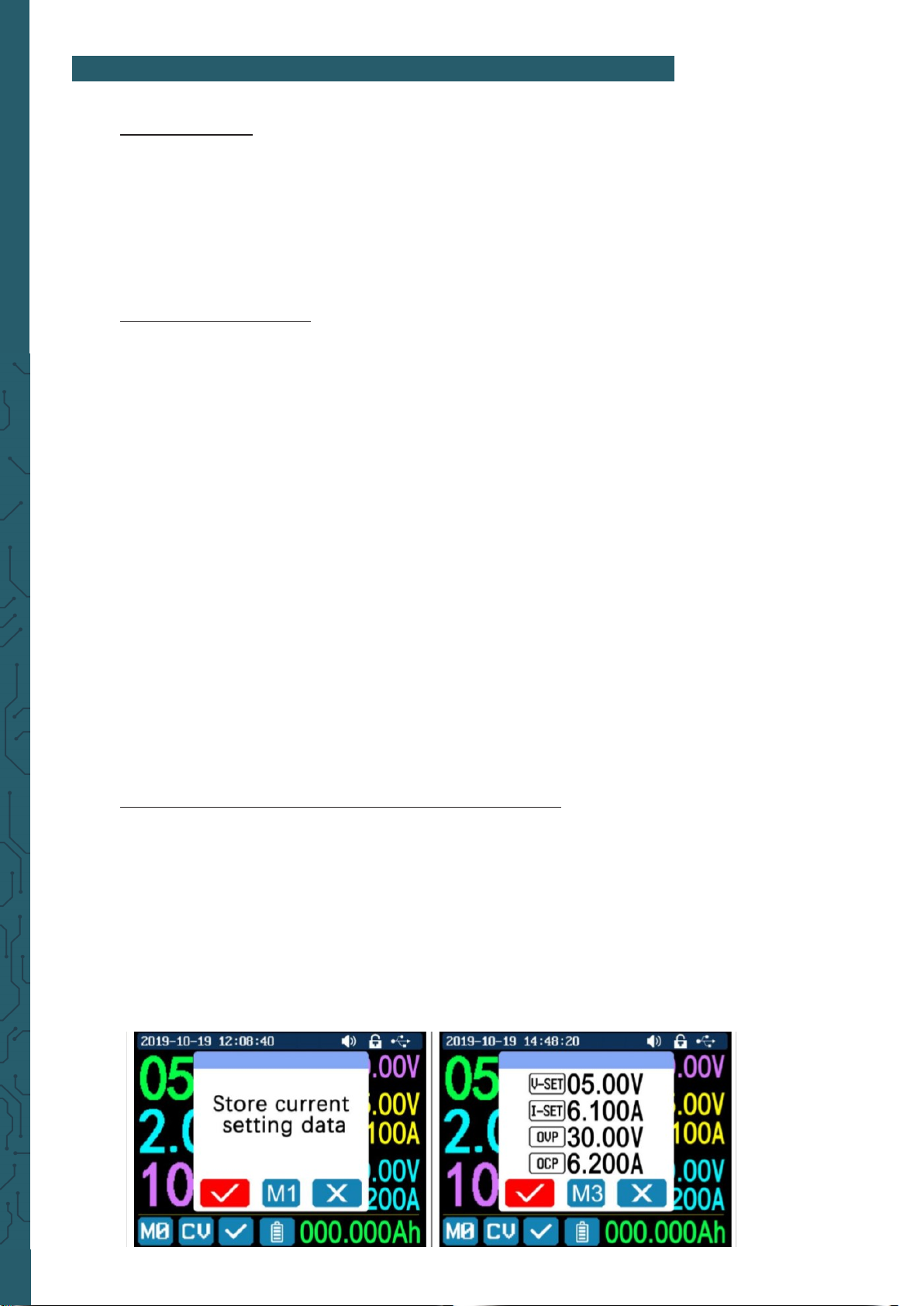
4. Data Group Quick Storage and Callout
Press 'MEM' +keypad button 1-9, you can store the output voltage value, output current value, overvoltage protection value, overcurrent protection value into the corresponding data group (as shown above), then press 'ENTER' to confirm, or press the
encoder to cancel. Press 'SHIFT' +keypad button 1-9 to quickly call out the saved data (as shown above). Press 'ENTER' to confirm, or press the encoder to cancel.
5. Keypad lock and unlock
Press 'SHIFT'+'.' to lock or unlock the keyboard. And the keypad will be automatically locked when communication starts,
there will be displayed on the top (can not unlock manually) and the keypad will
be automatically unlocked when the connection disconnected manually.
There will be displayed , the keypad will be automatically unlocked when the
connection disconnected abnormally and the power-o button can be used when the
keypad is locked.
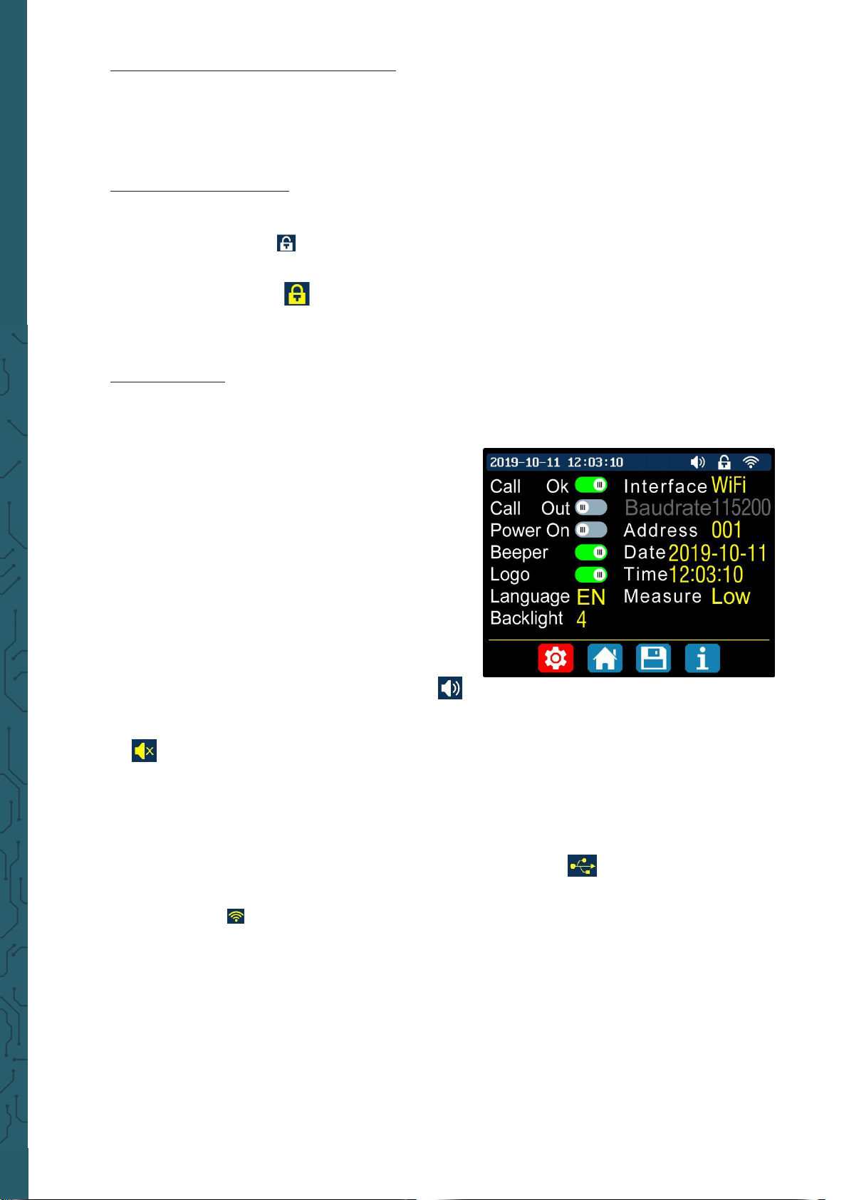
6. System Setting
Press 'SHIFT'+'0' to enter the system setting menu as shown on the right, press
'ENTER' to enter the menu, press direction button to select option, the option in
red is the option be chosen, rotate the encoder to change this setting.
Turn on the 'Call OK', a confirmation window will
pop up when you quick call out a data group. If
you turn it o, the setting values will be modified
directly when you call out a data group.
Turn on the 'Call out', the output will be turned
on automatically when you call out a data group. If
you turn it o, the output will keep the previous status.
Turn on the 'Power On', it will turn on the output
automatically when start. If you turn it o, the output will keep OFF status when started.
Turn on the 'Beeper', you will hear button tune
when pressing the button and there will be
on the top.
If you turn it o, there will not be button tune when press the button and there will
be on the top.
Turn on the “Logo”, it will display Logo first and then enter the main page when
booting RD6006 or RD6012. If you turn it o, you will enter the main page directly.
The system language supports English, German, French and Simplified Chinese.
The screen brightness can be set from level 0 to level 5.
The communication interface can be set to USB, Wi-Fi or TTL, USB interface is the Mi-
cro-USB interface on the front panel interface, you can see the
on the top when communication starts.
Wi-Fi interface is the Wi-Fi module connected to the communication interface,
you can see the on the top when communication starts (connect mobile phone
by Wi-Fi, but you need to choose Wi-Fi interface first, Wi-Fi module can not be in-
stalled or removed when RD6006 or RD6012 is powered on), TTL is not available for
the time being.
When the interface is changed, you need to reboot the device to apply the modifica-
tion. The baud rate can be set 9600/19200/38400/57600/115200 under USB mode;
The Baud rate under Wi-Fi is fixed at 115200. The device address can be set from 001-
255. You can set the date and time by rotating the encoder, the setting will be
saved immediately aer modification. Please do not set a wrong time, it may cause
the date to not be automatically accumulated. Press the encoder to return and the
set value will be saved automatically.
Measure is the refresh rate of read back voltage and current on the main page,
you can set it to low, middle and high. Press rotary encoder to return and it will be
automatically saved.
Pascalstr. 8 47506 Neukirchen-Vluyn
www.joy-it.net

7. Main Page Style setting
You can press 'SHIFT' + '0' to enter the system setting menu and then press the right
button to enter the main page style setting menu as shown above. Press ENTER and
then use the direction button to set classic style or curve style. The pattern in red is
the style be chosen. The classic style is the system default style and the large font
shows the voltage, current and power. The curve style is, as shown above, the colour
of the three curves corresponds to the output voltage, current and power. D is the
scale of the value, Press 'ENTER' to start or pause the curve and the rotary encoder
to scale the values of the curve.
8. Storage Data Setting
You can press 'SHIFT' + '0' to enter the system setting menu, then press the right
button twice to enter the data storage setting menu as shown below, press ENTER to
enter the setting menu, the icon in red is the chosen data group, press the direction
button to select data group number. Press 'I-SET' button to set the storage output
current value, then rotate the encoder to adjust the output value, press the direction
button to move the cursor. You can also set the value with keypad, press ENTER to
confirm. If you set the wrong value, you can press the encoder potentiometer to cancel. Press 'V-SET' button to set the storage output voltage value, the operation method is similar to storage output current setting. Press 'SHIFT'+ “'I-SET' button or
'SHIFT'+ 'V-SET' button to set the storage overcurrent protection/ storage overvoltage protection value. The operation method is similar to storage output current value setting. Press the Encoder Potentiometer to return and the data will be automatically saved.
9. System Information
You can press 'SHIFT' + '0' to enter the system setting menu, then press the right
button three times to enter the system information menu as shown above. You can
view the SN number, firmware version and system temperature here.
Pascalstr. 8 47506 Neukirchen-Vluyn
www.joy-it.net
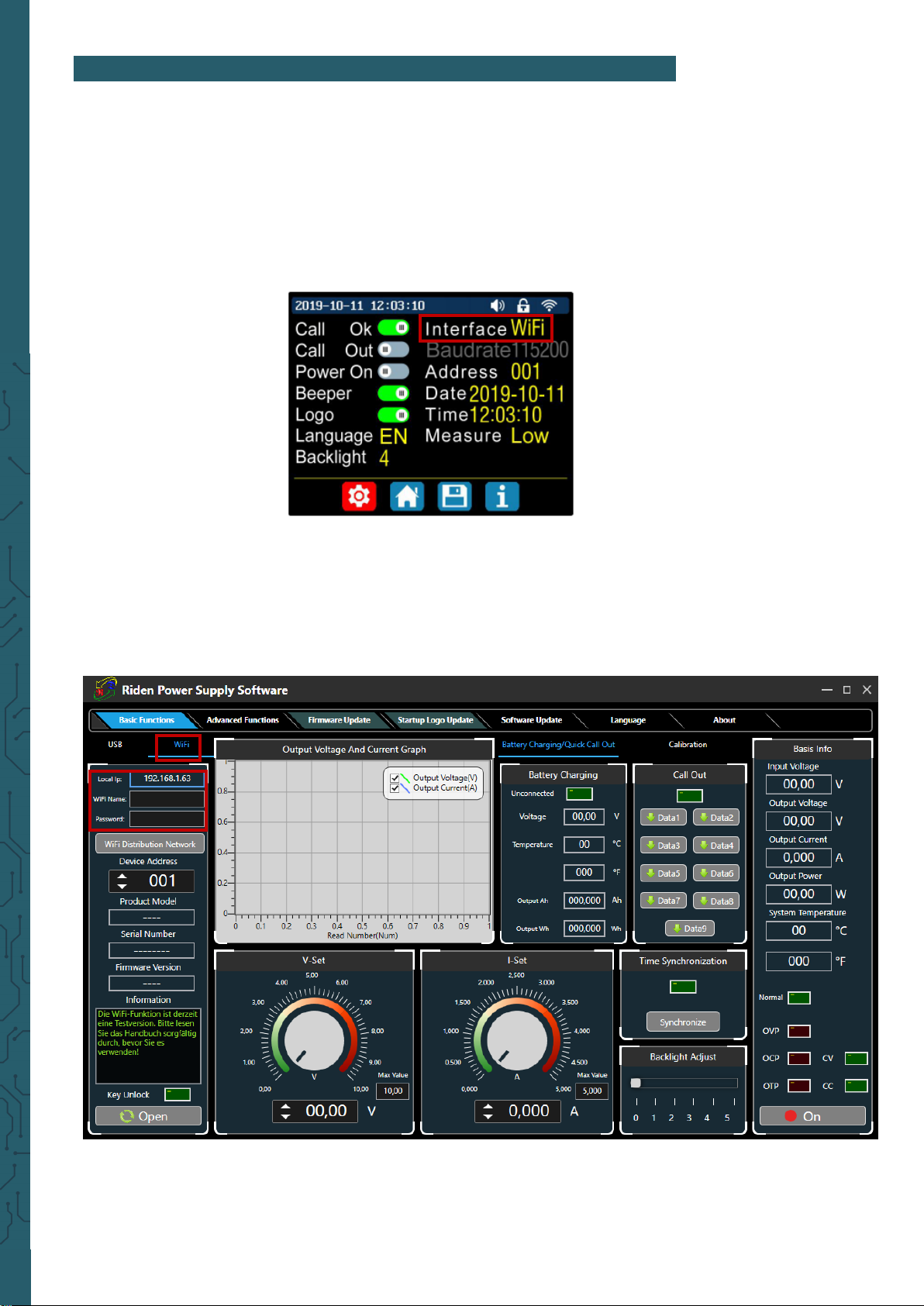
6. PC-SOFTWARE
To control the power supply from the app, you must first enable WiFi.
To do so, press Shi and then 0 to enter the menu.
Now press Enter and use the arrow keys to navigate to Interface.
Now turn the knob to select WiFi and press the knob several times to confirm and go back.
The changes will be applied aer restart of the power supply. The power
supply will automatically use the strongest WLAN network.
Make sure that your computer is on the same network.
Download the PC soware here.
Click WiFi, enter the name and password of your wireless network under
your displayed IP address, press WiFi Distribution and restart your power
supply.
Pascalstr. 8 47506 Neukirchen-Vluyn
www.joy-it.net

Once your IP address is displayed on your power supply, click Next.
If an incorrect IP address is displayed on your power supply, navigate to
Reset using the arrow keys and confirm with ENTER.
The IP is now determined again.
Your power supply unit now receives the necessary information to
connect to your computer. This may take a few seconds.
You can then connect your power supply unit to the PC soware by clicking on Connect in the lower le corner.
Pascalstr. 8 47506 Neukirchen-Vluyn
www.joy-it.net

Call up data groups
Graphical representation
Batteriestatus
Info
Connect /
Disconnect
Selected output
voltage
Data group selection
Maximum
Output voltage
Selected output current
Maximum
Output current
Output ON/OFF
Backgroundbrightness
Read data groups Write data groups
Pascalstr. 8 47506 Neukirchen-Vluyn
Intervals Setting
www.joy-it.net

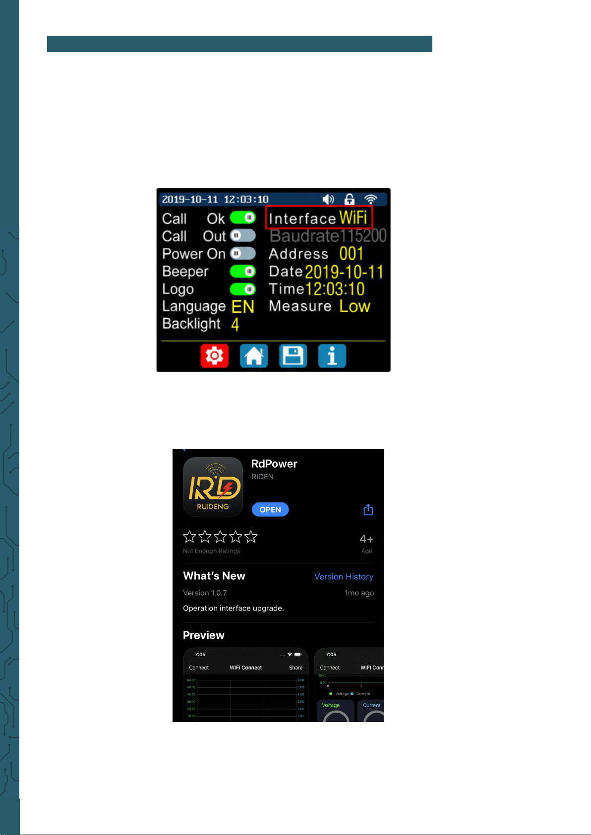
7. ANDROID APP
To control the power supply from the app, you must first enable WiFi.
To do so, press Shi and then 0 to enter the menu.
Now press Enter and use the arrow keys to navigate to Interface.
Now turn the knob to select WiFi and press the knob several times to go
back.
The power supply will automatically use the strongest WLAN network.
You must now restart the power supply.
Now install the App RdPower from Ruideng Technology from the Play
Store.
You must give the app the permissions it requires to work.
Pascalstr. 8 47506 Neukirchen-Vluyn
www.joy-it.net

Open the app and press the button in the upper le corner to enter the
menu.
Here you can see your IP address, you will need this later.
Now go to Distribution Network and also restart the power supply.
Pascalstr. 8 47506 Neukirchen-Vluyn
www.joy-it.net

You should now see the following in your app:
Once your IP address, which you could see in the app before, is displayed on
the screen of your power supply, you can click NEXT.
If an incorrect IP address is displayed on your power supply, use the arrow
keys to navigate to Reset and confirm with ENTER.
The IP is now determined again.
Now you have to enter the password of your WLAN network and click
Click CONFIRM.
Pascalstr. 8 47506 Neukirchen-Vluyn
www.joy-it.net

Aer a short wait, you can now connect your smartphone to your power
supply by clicking on CONNECT.
Now you can operate the power supply with your smartphone.
Please note, however, that the power supply cannot be adjusted manually
as long as your smartphone is connected.
Graphical
representation
Current output current
Current output voltage
Selected output voltage
Selected output current
Output ON/OFF
Current output power
Current input voltage
Knob
Le
Set
Right
System temperature
Backlighting
Pascalstr. 8 47506 Neukirchen-Vluyn
www.joy-it.net
Date group selection
8. IOS APP
To control the power supply from the app, you must first enable WiFi.
To do so, press Shi and then 0 to enter the menu.
Now press Enter and use the arrow keys to navigate to Interface.
Now turn the knob to select WiFi and press the knob several times to go
back.
You must now restart the power supply.
Now install the App RdPower from Ruideng Technology from the App
Store.
You must give the app the permissions it requires to work.
Pascalstr. 8 47506 Neukirchen-Vluyn
www.joy-it.net

Open now the app and move to the area named Distribution network
where you have to establish the connection with the device.
Click now on Init to start with the configuration.
Enter now your password of your network in case that the IP-address on
your iPhone is identical with the IP-address of your device. Aerwards,
click on Distribution to establish the connection.
If an incorrect IP address is displayed on your power supply, use the arrow
keys to navigate to Reset and confirm with ENTER.
The IP is now determined again.
Pascalstr. 8 47506 Neukirchen-Vluyn
www.joy-it.net

Aer, you have successfully connected, you can access the home screen in
the WiFi Connect area. There, you can activate the direct connection to the
device and use the functions of the RD6006.
Note, however, that the power supply can no longer be adjusted manually
while your phone is connected.
Connect / Disconnect
button
Graphical
representation
Current output voltage
Selected output voltage
Current output current
Current output power
Selected output current
Output ON/OFF
System temperature
Backlighting
Date group selection
Current input voltage
Pascalstr. 8 47506 Neukirchen-Vluyn
www.joy-it.net

9. ADDITIONAL INFORMATION
Our information and take-back obligations according to the
Electrical and Electronic Equipment Act (ElektroG)
PR
Symbol on electrical and electronic equipment:
This crossed-out dustbin means that electrical and electronic appliances
do not belong in the household waste. You must return the old appliances to a collection point.
Before handing over waste batteries and accumulators that are not enclosed by waste equipment must be separated from it.
Return options:
As an end user, you can return your old device (which essentially fulfils
the same function as the new device purchased from us) free of charge
for disposal when you purchase a new device.
Small appliances with no external dimensions greater than 25 cm can be
disposed of in normal household quantities independently of the purchase of a new appliance.
Possibility of return at our company location during opening hours:
Simac GmbH, Pascalstr. 8, D-47506 Neukirchen-Vluyn, Germany
Possibility of return in your area:
We will send you a parcel stamp with which you can return the device to
us free of charge. Please contact us by e-mail at Service@joy-it.net or by
telephone.
Information on packaging:
If you do not have suitable packaging material or do not wish to use your
own, please contact us and we will send you suitable packaging.
10. SUPPORT
If there are still any issues pending or problems arising aer your purchase, we will support you by e-mail, telephone and with our ticket support
system.
E-Mail: service@joy-it.net
Ticket system: http://support.joy-it.net
Telephone: +49 (0)2845 98469-66 (10-17 o‘clock)
For further information please visit our website:
www.joy-it.net
Published: 03.03.2021
Pascalstr. 8, 47506 Neukirchen-Vluyn
Pascalstr. 8 47506 Neukirchen-Vluyn
www.joy-it.net
www.joy-it.net
SIMAC Electronics GmbH
 Loading...