

Page 1
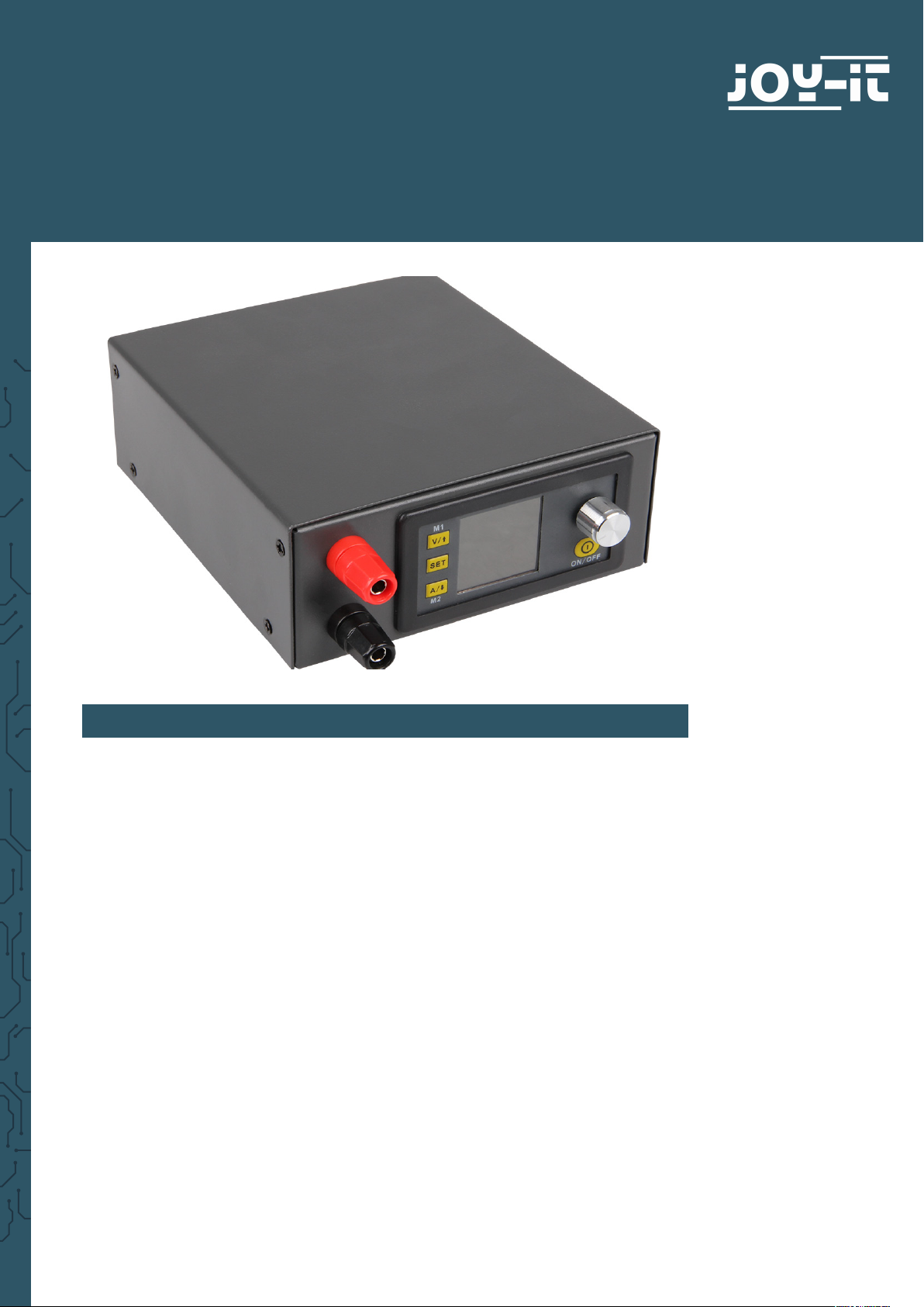
DPS CASE
Case for the JT-DPS5015, JT-DPS5005 and JT-DPH5005
1. GENERAL INFORMATION
Dear customer,
thank you for purchasing our product. The following is a manual for the
assembling of a case for DPS5015, DPS5005 and DPH5005.
Should you have any problems, do not hesitate to contact us.
Page 2
2. COMPONENTS
3. ASSEMBLY OF THE CASE
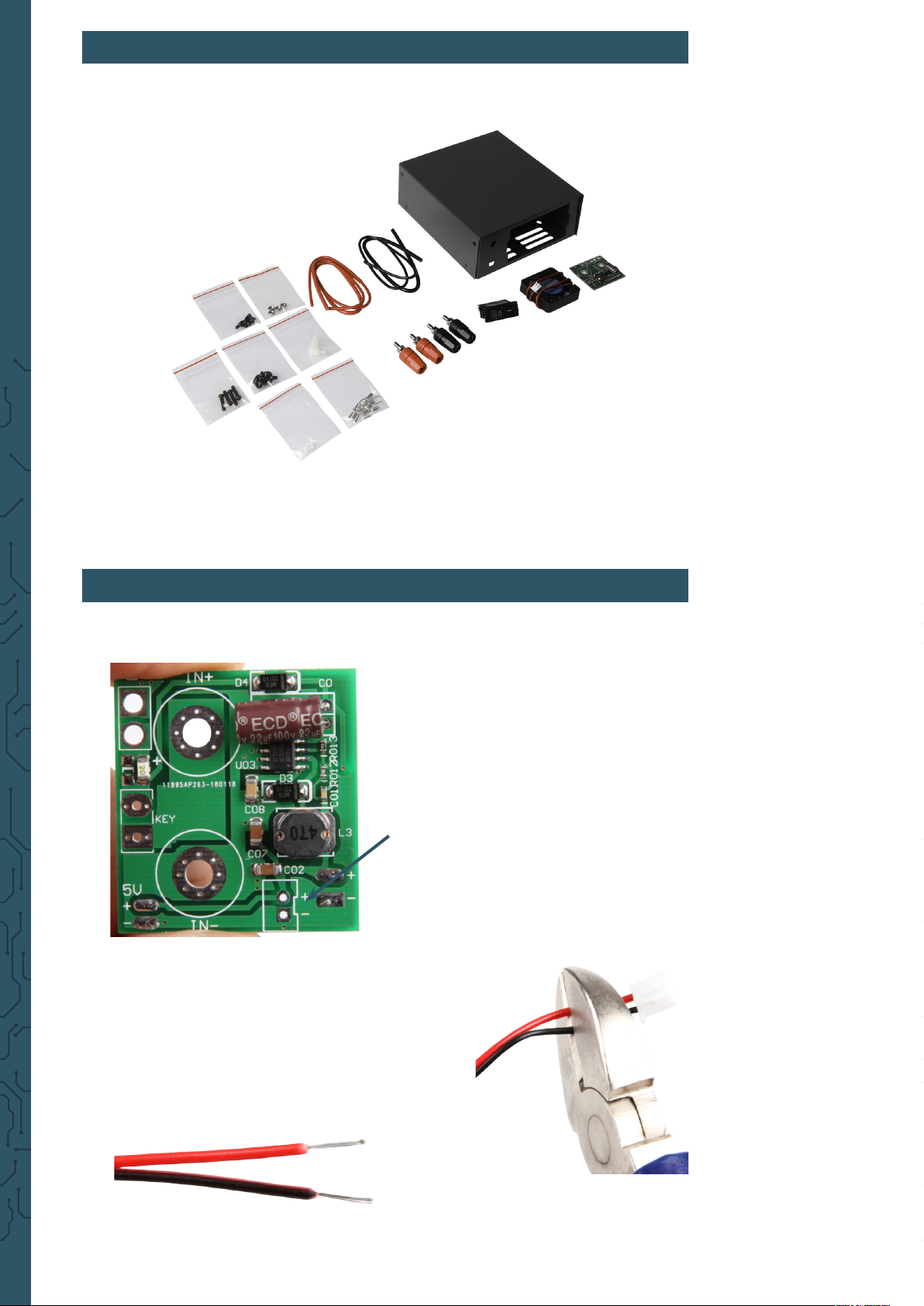
Prepare the needed components.
To facilitate the assembling, you should
begin with the small board from the case.
You have to solder a fan on the board,
also a toggle switch and a cable have to
be pursued to the mainboard.
The mainboard does not have a port for
the fan. That is the reason that it has to be
soldered on to the small board.
Therefore, the cable of the included fan has to
be cut.
You must be very careful when you relieve the
insulation from the cable core. The cores have
to be free of insulation about 4 mm.
Page 3
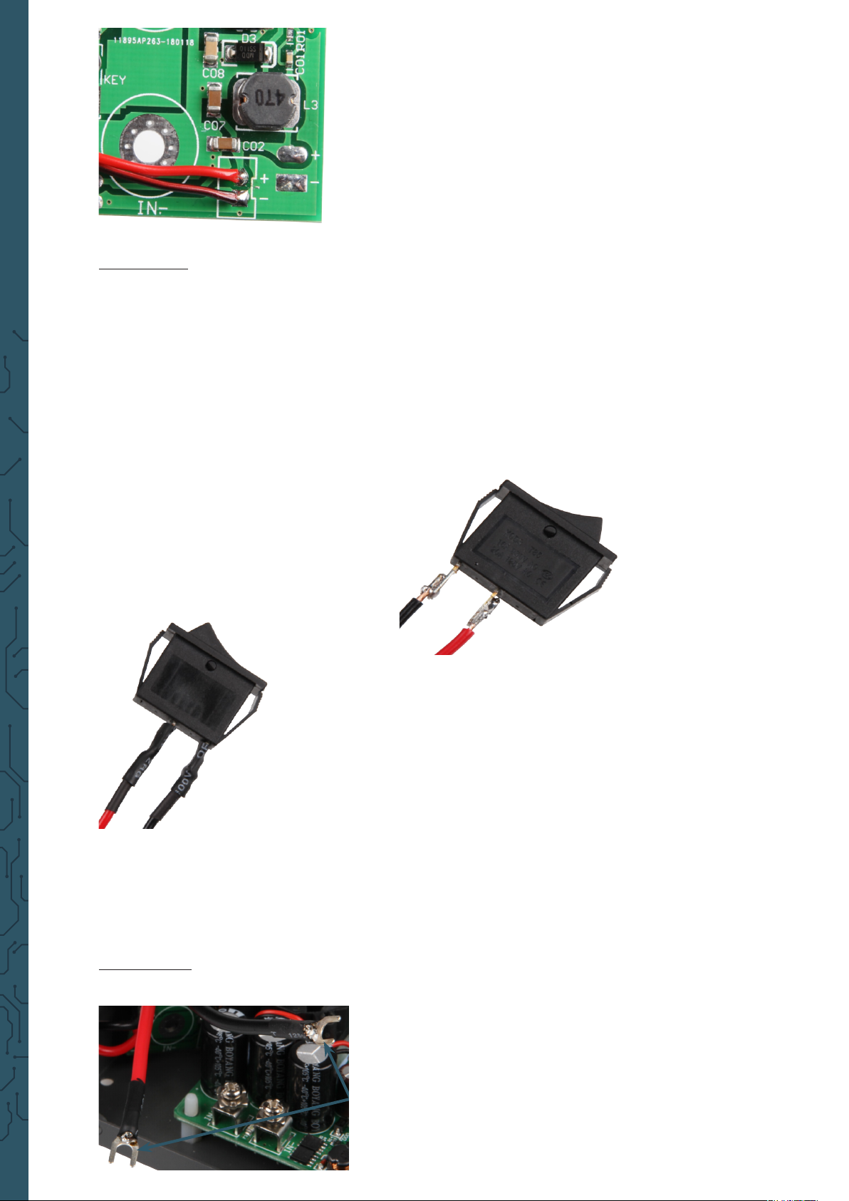
The red cable (+) must be soldered on
“+“ and the black one (-) on the board
at “-“.
Pull beforehand the stripped ends
through the holes and solder from
both sides.
Attention: Cut the cable cores on the backside with a side cutter o so
that they will not cause a short later!
First must be the switch soldered that
the lab power supply can be switched
on and o. For that, you use the red and
the black cable with the small diameter.
Solder them at the switch like shown in
the picture.
To prevent a short, you should isolate the
contacts with shrinking tubes.
Now the supply from the small board to the mainboard must be prepared
and aerwards soldered.
For this supply, you need the cables ( the red “+“ and the black “-“) with the
bigger diameter. You cut both aer a length of 9 cm o.
Attention: Do not cut too much of the cable o, otherwise the cable
could be too short for the outputs later on.
Both sides must be about 5mm at the
end stripped because on both ends
have to be forked cable lugs attached.
These ends should be isolated with
shrinking tubes either to prevent
shorts.
Page 4

The other end of the cable must be soldered on to the small board.
Have in mind the dierent polarities of
both cables.
Red = „+“ and Black = „-“
Now you can solder the switch. Have in
mind that the cables must go later on
through the case or attach the switch
beforehand. The ends of the cables at
the switch have to get soldered at the
pads “KEY“. Solder the red cable on to the
rectangle pad and the black one on to the
round pad.
Now you can attach the mainboard with four screws at the bottom of the
case and integrate the inputs and outputs of the power supply.
Ports at the front:
Screw the ports at the case and attach the red ports
at the top and the black ones at the bottom like
that:
Ports at the back:
inside outside
Page 5

As soon as you have nished, you
begin to prepare the cables for the
output.
For that, you need again the cables
with the bigger diameter and strip
down about 5 mm on both sides.
Attach forked cable lugs on both sides.
Now you can install the fan from the inside
of the case. For this, four nuts must be
plugged in from the back into the fan and
four screws must be screwed from the
outside of the case to mount the fan.
Aer the cables are connected and the fan
is mounted, you can install the small board
with two nuts at the case.
If the small board is installed, you can plug all
cables in.
First, mount the cable for the input voltage
(“IN+“ and “IN-“).
Next, mount the cable for the
output voltage
(“OUT+“ and “OUT-“).
The end of the cable from the output voltage must
be conntected with the ports in the front.
Page 6

In the end, you only have to connect the
display. You have to connect two cables
with the mainboard. One cable is for
the display (“LCD“) and one for the keys
(“KEY“). The ports for the cables are
marked on the board as well as on the
display. As soon as you have the cable
connected, you must only mount the
display at the case.
When all cables are plugged in, the boards screwed, the display and the
switch mounted and the fan installed, you have nished the
assembly of the case.
Now you can mount the case with four screws on both sides together.
Page 7

4. JT-DPS-USB & JT-DPS-BT (OPTIONAL PURCHASABLE)
To set up the lab power supply on your computer, you need a micro-USB
module that can be optionally purchased. This module can be installed in
the case either.
The BT module is built to control the lab supply via your smartphone. This
module can be installed in the case as well as the microUSB module.
First of all, those spacers must be
mounted at the module.
The module is going to be screwed next to the small
board from beneath the case.
The module then must be
plugged on to the mainboard.
The DPS5005 and the DPH5005 can
both use the two modules either.
But the place of the port which is
used for the modules, depends on
the model.
You should note that the case could
aect the range of the BT module.
The necessary soware can be downloaded from our website:
www.joy-it.net
Page 8

5. JT-DPS5005
The JT-DPS-Case can be used with our JT-DPS5015, our JT-DPS5005 and
our JT-DPH5005. The JT-DPS5005 does not have a separate board like the
JT-DPS5015 and the JT-DPH5005, the assembly of the case is a little bit
dierent.
The input voltage and the output voltage
of the case must be plugged in to the
intented 4-pole PCB plug.
Page 9

6. FINISHED DPS-CASE WITH DPS5015
7. SUPPORT
We are there for you aer your purchase. If any questions remain open or
any problems arise, we are available by e-mail, telephone and ticket
support system.
E-mail: service@joy-it.net
Ticket-system: http://support.joy-it.net
Telephone: +49 (0)2845 98469 – 66 (10 - 17 o‘clock)
For more information visit our website:
www.joy-it.net
Published 26.06.2019
www.joy-it.net
Simac Electronics Handel GmbH
Pascalstr. 8 47506 Neukirchen-Vluyn
 Loading...