


CENTRIFUGE |
C3i /CR3i |
SERVICE MANUAL |

CENTRIFUGE
C3i /CR3i
SERVICE MANUAL
89000832-a
CAREFULLY READ THIS MANUAL BEFORE OPERATING YOUR INSTRUMENT.
INFORMATION CONTAINED IN THIS DOCUMENT IS THE PROPERTY OF JOUAN ;
IT MAY NOT BE DUPLICATED OR DISTRIBUTED WITHOUT THE OWNER’S AUTHORIZATION.

REVISION STATUS
INDEX |
DATE |
AMENDED PAGES |
NOTES |
|
|
|
|
a |
03/98 |
|
Initial release |
|
|
|
|
C3i-M

WARRANTY
Subject to the due observance of any installation, operating or maintenance instructions, we warrant that we will at our option replace, or repair free of charge, or credit the purchaser with the full invoice price of any goods or parts of goods of our own manufacture proved to be defective owing to faulty workmanship or materials, provided that we are notified in writing of the alleged defect within 12 months of the date of despatch of the goods and the goods are returned to us promptly on discovery of the alleged defect with details of the manner and circumstances in which they are alleged to have become defective.
Replaced goods become our property.
Goods not manufactured by us are only guaranteed to the guarantee given to us by the actual manufacturers.
Our obligations in respect of defective goods set out above are exclusive and expressly in lieu of all other terms, warranties and conditions, expressed or implied (including without prejudice to the generality of the foregoing) warranties and conditions or merchantability and fitness for a particular purpose all of which terms warranties and conditions are hereby expressly excluded.
It is a condition of sale that the purchaser agrees to keep us indemnified at all times in respect of all actions proceedings, claims and demands whatsoever which may be made by any third party against us for any loss or damage howsoever arising (including with prejudice to the generality of the foregoing loss or damage arising out of the negligence of our employees or agents) which may be caused by goods sold to the purchaser, and all costs and expenses incurred by us in connection therewith.
All liability for loss of profit, consequential loss, or any other loss whatsoever suffered by the purchaser howsoever arising (including without prejudice to the generality of the foregoing loss arising out of our negligence of our servants or agents) is hereby expressly excluded.
In the event that purchaser makes any claims for such or any loss or damage against any of our employees or agents, it shall pay to us the amount (if any) recovered from such employee or agent and an amount equal to the legal costs (on a full indemnity basis) incurred by such employee or agent in defending or compromising the purchaser's claim).
C3i-M

CONTENTS
CHAPTER 1 - INTRODUCTION . . . . . . . . . . . . . . . . . . . . . . . . . . . . . . . . . . . . . . . . . . . . . . . . . . . . . . . . . . . . |
1-1 |
1.1. Purpose . . . . . . . . . . . . . . . . . . . . . . . . . . . . . . . . . . . . . . . . . . . . . . . . . . . . . . . . . . . . . . . . . . . . . . . . . . . . . . . 1-1 1.2. Presentation . . . . . . . . . . . . . . . . . . . . . . . . . . . . . . . . . . . . . . . . . . . . . . . . . . . . . . . . . . . . . . . . . . . . . . . . . . . 1-1 1.3. Specifications . . . . . . . . . . . . . . . . . . . . . . . . . . . . . . . . . . . . . . . . . . . . . . . . . . . . . . . . . . . . . . . . . . . . . . . . . . 1-2 1.3.1. Dimensions and weight . . . . . . . . . . . . . . . . . . . . . . . . . . . . . . . . . . . . . . . . . . . . . . . . . . . . . . . . . . . 1-2 1.3.2. Electrical specifications . . . . . . . . . . . . . . . . . . . . . . . . . . . . . . . . . . . . . . . . . . . . . . . . . . . . . . . . . . 1-2 1.3.3. Performance . . . . . . . . . . . . . . . . . . . . . . . . . . . . . . . . . . . . . . . . . . . . . . . . . . . . . . . . . . . . . . . . . . . . 1-2
1.4. Installation procedure . . . . . . . . . . . . . . . . . . . . . . . . . . . . . . . . . . . . . . . . . . . . . . . . . . . . . . . . . . . . . . . . . . . 1-3
CHAPTER 2 - THEORY OF OPERATION . . . . . . . . . . . . . . . . . . . . . . . . . . . . . . . . . . . . . . . . . . . . . . . . . . . . . |
2-1 |
||
2.1. |
Description . . . . . . . . . . . . . . . . . . . . . . . . . . . . . . . . . . . . . . . . . . . . . . . . . . . . . . . . . . . . . . . . . . . . . . . . . . . . |
2-1 |
|
2.2. |
Component lay-out . . . . . . . . . . . . . . . . . . . . . . . . . . . . . . . . . . . . . . . . . . . . . . . . . . . . . . . . . . . . . . . . . . . . . |
2-1 |
|
2.3. |
Motor control principle . . . . . . . . . . . . . . . . . . . . . . . . . . . . . . . . . . . . . . . . . . . . . . . . . . . . . . . . . . . . . . . . . . |
2-6 |
|
|
2.3.1. |
Introduction . . . . . . . . . . . . . . . . . . . . . . . . . . . . . . . . . . . . . . . . . . . . . . . . . . . . . . . . . . . . . . . . . . . . |
2-6 |
|
2.3.2. |
The motor . . . . . . . . . . . . . . . . . . . . . . . . . . . . . . . . . . . . . . . . . . . . . . . . . . . . . . . . . . . . . . . . . . . . . . |
2-6 |
|
2.3.3. |
Power control . . . . . . . . . . . . . . . . . . . . . . . . . . . . . . . . . . . . . . . . . . . . . . . . . . . . . . . . . . . . . . . . . . . |
2-7 |
2.4. |
Electronics - structure . . . . . . . . . . . . . . . . . . . . . . . . . . . . . . . . . . . . . . . . . . . . . . . . . . . . . . . . . . . . . . . . . . . |
2-8 |
|
|
2.4.1. |
Introduction . . . . . . . . . . . . . . . . . . . . . . . . . . . . . . . . . . . . . . . . . . . . . . . . . . . . . . . . . . . . . . . . . . . . |
2-8 |
|
2.4.2. Microprocessor + power pcb . . . . . . . . . . . . . . . . . . . . . . . . . . . . . . . . . . . . . . . . . . . . . . . . . . . . . |
2-9 |
|
|
2.4.3. |
Imbalance sensor . . . . . . . . . . . . . . . . . . . . . . . . . . . . . . . . . . . . . . . . . . . . . . . . . . . . . . . . . . . . . . . |
2-10 |
|
2.4.4. |
Tacho sensor . . . . . . . . . . . . . . . . . . . . . . . . . . . . . . . . . . . . . . . . . . . . . . . . . . . . . . . . . . . . . . . . . . . |
2-10 |
|
2.4.5. |
Temperature sensor (CR3i) . . . . . . . . . . . . . . . . . . . . . . . . . . . . . . . . . . . . . . . . . . . . . . . . . . . . . . . |
2-10 |
|
2.4.6. Refrigeration control board (CR3i) . . . . . . . . . . . . . . . . . . . . . . . . . . . . . . . . . . . . . . . . . . . . . . . . . |
2-10 |
|
|
2.4.7. |
Input - output . . . . . . . . . . . . . . . . . . . . . . . . . . . . . . . . . . . . . . . . . . . . . . . . . . . . . . . . . . . . . . . . . . . . |
2-11 |
CHAPTER 3 - DIAGNOSTICS AND REPAIRS . . . . . . . . . . . . . . . . . . . . . . . . . . . . . . . . . . . . . . . . . . . . . . . . . . |
3-1 |
||
3.1. |
Introduction . . . . . . . . . . . . . . . . . . . . . . . . . . . . . . . . . . . . . . . . . . . . . . . . . . . . . . . . . . . . . . . . . . . . . . . . . . . |
3-1 |
|
3.2. |
Functional test . . . . . . . . . . . . . . . . . . . . . . . . . . . . . . . . . . . . . . . . . . . . . . . . . . . . . . . . . . . . . . . . . . . . . . . . . |
3-1 |
|
|
3.2.1. |
EPROM version . . . . . . . . . . . . . . . . . . . . . . . . . . . . . . . . . . . . . . . . . . . . . . . . . . . . . . . . . . . . . . . . . |
3-1 |
|
3.2.2. |
Test mode . . . . . . . . . . . . . . . . . . . . . . . . . . . . . . . . . . . . . . . . . . . . . . . . . . . . . . . . . . . . . . . . . . . . . . |
3-1 |
3.3. |
Fault codes . . . . . . . . . . . . . . . . . . . . . . . . . . . . . . . . . . . . . . . . . . . . . . . . . . . . . . . . . . . . . . . . . . . . . . . . . . . . |
3-5 |
|
3.4. |
Troubleshooting chart . . . . . . . . . . . . . . . . . . . . . . . . . . . . . . . . . . . . . . . . . . . . . . . . . . . . . . . . . . . . . . . . . . . |
3-6 |
|
CHAPTER 4 - REPLACEMENT PROCEDURES . . . . . . . . . . . . . . . . . . . . . . . . . . . . . . . . . . . . . . . . . . . . . . . . |
4-1 |
||
4.1. |
Motor replacement . . . . . . . . . . . . . . . . . . . . . . . . . . . . . . . . . . . . . . . . . . . . . . . . . . . . . . . . . . . . . . . . . . . . . |
4-1 |
|
|
4.1.1. |
Unrefrigerated model (C3i) . . . . . . . . . . . . . . . . . . . . . . . . . . . . . . . . . . . . . . . . . . . . . . . . . . . . . . . |
4-1 |
|
4.1.2. |
Refrigerated model (CR3i) . . . . . . . . . . . . . . . . . . . . . . . . . . . . . . . . . . . . . . . . . . . . . . . . . . . . . . . . |
4-2 |
4.2. |
Imbalance detector replacement . . . . . . . . . . . . . . . . . . . . . . . . . . . . . . . . . . . . . . . . . . . . . . . . . . . . . . . . . |
4-3 |
|
4.3. |
Replacement of the lid lock assembly . . . . . . . . . . . . . . . . . . . . . . . . . . . . . . . . . . . . . . . . . . . . . . . . . . . . . . |
4-3 |
|
4.4. |
Lid lock assembly element replacement . . . . . . . . . . . . . . . . . . . . . . . . . . . . . . . . . . . . . . . . . . . . . . . . . . . |
4-4 |
|
|
4.4.1. Lid lock microswitch replacement . . . . . . . . . . . . . . . . . . . . . . . . . . . . . . . . . . . . . . . . . . . . . . . . . |
4-4 |
|
|
4.4.2. |
Lid lock replacement . . . . . . . . . . . . . . . . . . . . . . . . . . . . . . . . . . . . . . . . . . . . . . . . . . . . . . . . . . . . |
4-4 |
|
4.4.3. Lock solenoid microswitch replacement . . . . . . . . . . . . . . . . . . . . . . . . . . . . . . . . . . . . . . . . . . . . |
4-4 |
|
|
4.4.4. |
Solenoid replacement . . . . . . . . . . . . . . . . . . . . . . . . . . . . . . . . . . . . . . . . . . . . . . . . . . . . . . . . . . . . |
4-5 |
4.5. |
Power supply rack replacement . . . . . . . . . . . . . . . . . . . . . . . . . . . . . . . . . . . . . . . . . . . . . . . . . . . . . . . . . . |
4-5 |
|
|
4.5.1. Rack replacement for the C3i . . . . . . . . . . . . . . . . . . . . . . . . . . . . . . . . . . . . . . . . . . . . . . . . . . . . . |
4-5 |
|
|
4.5.2. Rack replacement for the CR3i . . . . . . . . . . . . . . . . . . . . . . . . . . . . . . . . . . . . . . . . . . . . . . . . . . . . |
4-6 |
|
|
4.5.3. |
Refrigeration board replacement (CR3i) . . . . . . . . . . . . . . . . . . . . . . . . . . . . . . . . . . . . . . . . . . . . . |
4-6 |
C3i-M

4.6. |
Electronic board replacement . . . . . . . . . . . . . . . . . . . . . . . . . . . . . . . . . . . . . . . . . . . . . . . . . . . . . . . . . . . . |
4-7 |
|
4.6.1. Microprocessor + power pcb . . . . . . . . . . . . . . . . . . . . . . . . . . . . . . . . . . . . . . . . . . . . . . . . . . . . . |
4-7 |
|
4.6.2. Display board . . . . . . . . . . . . . . . . . . . . . . . . . . . . . . . . . . . . . . . . . . . . . . . . . . . . . . . . . . . . . . . . . . . |
4-8 |
4.7. |
Keyboard replacement . . . . . . . . . . . . . . . . . . . . . . . . . . . . . . . . . . . . . . . . . . . . . . . . . . . . . . . . . . . . . . . . . |
4-8 |
4.8. |
Gas spring replacement . . . . . . . . . . . . . . . . . . . . . . . . . . . . . . . . . . . . . . . . . . . . . . . . . . . . . . . . . . . . . . . . . |
4-8 |
|
4.8.1. Gas spring replacement on the C3i . . . . . . . . . . . . . . . . . . . . . . . . . . . . . . . . . . . . . . . . . . . . . . . . |
4-8 |
|
4.8.2. Gas spring replacement on the CR3i . . . . . . . . . . . . . . . . . . . . . . . . . . . . . . . . . . . . . . . . . . . . . . . |
4-9 |
4.9. |
Tacho replacement . . . . . . . . . . . . . . . . . . . . . . . . . . . . . . . . . . . . . . . . . . . . . . . . . . . . . . . . . . . . . . . . . . . . . |
4-9 |
4.10. |
EPROM replacement . . . . . . . . . . . . . . . . . . . . . . . . . . . . . . . . . . . . . . . . . . . . . . . . . . . . . . . . . . . . . . . . . . . . |
4-10 |
4.11. |
Lid replacement . . . . . . . . . . . . . . . . . . . . . . . . . . . . . . . . . . . . . . . . . . . . . . . . . . . . . . . . . . . . . . . . . . . . . . . . |
4-10 |
4.12. |
Refrigeration group repairs (CR3i) . . . . . . . . . . . . . . . . . . . . . . . . . . . . . . . . . . . . . . . . . . . . . . . . . . . . . . . . |
4-11 |
|
4.12.1. Refrigeration group replacement . . . . . . . . . . . . . . . . . . . . . . . . . . . . . . . . . . . . . . . . . . . . . . . . . . . |
4-11 |
|
4.12.2. Condenser components replacement . . . . . . . . . . . . . . . . . . . . . . . . . . . . . . . . . . . . . . . . . . . . . . . |
4-12 |
4.13 |
Motor checking . . . . . . . . . . . . . . . . . . . . . . . . . . . . . . . . . . . . . . . . . . . . . . . . . . . . . . . . . . . . . . . . . . . . . . . . |
4-12 |
4.14 |
Checking and maintenance of the centering group . . . . . . . . . . . . . . . . . . . . . . . . . . . . . . . . . . . . . . . . . . |
4-13 |
CHAPTER 5 - CHECKS, ADJUSTMENTS, CALIBRATION . . . . . . . . . . . . . . . . . . . . . . . . . . . . . . . . . . . . . . . . |
5-1 |
|
5.1. |
Imbalance adjustment . . . . . . . . . . . . . . . . . . . . . . . . . . . . . . . . . . . . . . . . . . . . . . . . . . . . . . . . . . . . . . . . . . |
5-1 |
5.2. |
Temperature sensor calibration (CR3i) . . . . . . . . . . . . . . . . . . . . . . . . . . . . . . . . . . . . . . . . . . . . . . . . . . . . . |
5-2 |
CHAPTER 6 - SPARE PARTS - DIAGRAMS . . . . . . . . . . . . . . . . . . . . . . . . . . . . . . . . . . . . . . . . . . . . . . . . . . . . |
6.1 |
|
6.1. |
General . . . . . . . . . . . . . . . . . . . . . . . . . . . . . . . . . . . . . . . . . . . . . . . . . . . . . . . . . . . . . . . . . . . . . . . . . . . . . . . |
6-1 |
6.2. |
Motor . . . . . . . . . . . . . . . . . . . . . . . . . . . . . . . . . . . . . . . . . . . . . . . . . . . . . . . . . . . . . . . . . . . . . . . . . . . . . . . |
6-2 |
6.3. |
AUTO-LOCK system . . . . . . . . . . . . . . . . . . . . . . . . . . . . . . . . . . . . . . . . . . . . . . . . . . . . . . . . . . . . . . . . . . . . |
6-3 |
6.4. |
Lock . . . . . . . . . . . . . . . . . . . . . . . . . . . . . . . . . . . . . . . . . . . . . . . . . . . . . . . . . . . . . . . . . . . . . . . . . . . . . . . |
6-4 |
6.5. |
Feeder group . . . . . . . . . . . . . . . . . . . . . . . . . . . . . . . . . . . . . . . . . . . . . . . . . . . . . . . . . . . . . . . . . . . . . . . . . . |
6-5 |
6.6. |
Refrigeration group (CR3i) . . . . . . . . . . . . . . . . . . . . . . . . . . . . . . . . . . . . . . . . . . . . . . . . . . . . . . . . . . . . . . . |
6-6 |
6.7. |
Condenser group (CR3i) . . . . . . . . . . . . . . . . . . . . . . . . . . . . . . . . . . . . . . . . . . . . . . . . . . . . . . . . . . . . . . . . |
6-7 |
APPENDIX A - RECOMMENDED LIST OF TOOLS . . . . . . . . . . . . . . . . . . . . . . . . . . . . . . . . . . . . . . . . . . . . . |
A-1 |
|
APPENDIX B - ELECTRICAL DIAGRAMS . . . . . . . . . . . . . . . . . . . . . . . . . . . . . . . . . . . . . . . . . . . . . . . . . . . . |
B-1 |
|
C3i-M

1 - 1
1 INTRODUCTION
1.1. PURPOSE
This manual contains maintenance instructions intended for use by a qualified maintenance or service technician. It is organized to provide maintenance personnel with basic data on the theory of operation to assist in troubleshooting. Moreover, it outlines parts replacement and calibration procedures for putting the centrifuges back into service.
Should a specific maintenance problem arise which is not covered in this manual, please ask the authorized service organization in your area for assistance, or contact our after sales department :
JOUAN SA
AFTER SALES SERVICE
C.P. 3203, 44805 SAINT-HERBLAIN CEDEX - FRANCE
Tel. +33 (0) 2 40 16 80 00 - Fax : +33 (0) 2 40 94 70 16
Telex : 711062 JOUAN NT
JOUAN LTD |
JOUAN GmbH |
Merlin Way, Quarry Hill Road |
Kapellenstrasse 22 |
ILKESTON, DERBYS, DE7 4RA - U.K. |
82008 UNTERHACHING - GERMANY |
Tel. (0115) 944 7989 |
Tel. : (089) 611 4038 |
Fax : (0115) 944 7080 |
Fax : (089) 611 3087 |
JOUAN INC.
Delivery address : 110-B Industrial Drive, WINCHESTER, VA 22602 - U.S.A
Postal address : P.O. Box 2716, WINCHESTER, VA 22604-9879 - U.S.A
Tel. (540) 869 8623 - Fax : (540) 869 8626 - Toll free : (800) 662 7477
1.2. PRESENTATION
The C3i and CR3i (refrigerated) centrifuges are instruments designed for laboratory use. Using relative centrifuge force (RCF) allows elements of different density to be separated.
The rotor is the main load; a swing-out design allows a higher load than does an angle design. The larger the rotor diameter is, the higher the load can be and thus the slower the speed will be.
The RCF is directly proportional to the radius of sedimentation and to the square of the speed.
The gas used in the refrigeration system (CR3i) is R134a, without CFC, recommended by the directive for protection of the ozone layer.
C3i-M

1 - 2
1.3. SPECIFICATIONS
1.3.1.DIMENSIONS AND WEIGHT
Dimensions (H x W x D) Packed (H x W x D) Weight - uncrated / crated
1.3.2.ELECTRICAL SPECIFICATIONS
Mains supply 220/240 VAC 50 Hz Mains supply 120 VAC 60 Hz
Max power Average power Refrigeration
1.3.3.PERFORMANCE
Max speed
Max RCF
Max capacity Microprocessor controlled Display
Memory size Program protection Speed
Timer
Acceleration rates Braking rates Temperature (CR3i)
Typical performance
Maximum density Maximum energy
C3i : 372 x 400 x 495 mm |
CR3i : 375 x 575 x 605 mm |
||
C3i : |
600 x 610 x 540 mm |
CR3i : |
590 x 720 x 710 mm |
C3i : |
40 kg / 52 kg |
CR3i : |
72 kg / 85 kg |
C3i : |
11175700 |
CR3i : |
11175703 |
C3i : |
11175701 |
CR3i : |
11175704 |
C3i : |
500 W |
CR3i : |
800 W |
C3i : |
350 W |
CR3i : |
550 W |
|
|
CR3i : |
235 W |
Swing-out : 4 000 rpm (C3i) |
Angle : 14 000 rpm |
|
Swing-out : 4 100 rpm (CR3i) |
|
|
Swing-out : 3 934 x g (C3i) |
Angle : 18 407 x g |
|
Swing-out : 3 082 rpm (CR3i) |
|
|
Swing-out : 4 x 280 ml |
Angle : 6 x 100 ml |
|
High visibility digital display |
|
|
5 programs, direct access |
|
|
Recall key lock |
|
|
Range |
500 to 14 000 rpm |
|
Step |
10 -100 rpm |
|
Accuracy |
± 20 rpm |
|
Range |
30 sec to 99 min + hold position |
|
Step |
30 sec to 1 min |
|
5 |
|
|
5 |
|
|
Range |
-9°C to +40°C |
|
Step |
1°C |
|
Accuracy |
± 1.5°C |
|
4°C at 4 000 rpm, (4 x 280 ml swing-out) 1°C at 14 000 rpm, (20 x 1.5 ml angle)
1.2 g/cm3
14 400 J
C3i-M

1 - 3
1.4. INSTALLATION PROCEDURE
The environment must not be in a dusty room or corrosive environment.
The bench top must be of a rigid construction capable of supporting the weight of the centrifuge.
IMPORTANT : at least two people are required to lift the centrifuge from the palette and place it on the bench.
WARNING : The rear panel of the instrument must be at least 30 cm from the walls to allows hot air coming from the condenser to escape.
C3i-M

2 - 1
2 THEORY OF OPERATION
2.1. DESCRIPTION
The microprocessor system which controls the C3i or CR3i centrifuges ensures the operation of the following major elements :
-Management of the operating modes
-Generation of alternating current amplitude and frequency
-Adjustable components for the motor speed servo
-Management of the acceleration and braking profile/rates
-Management of the temperature regulation (CR3i)
-Management of the safety devices :
. Lid lock
. Zero speed detection
. Imbalance detection
. Motor overtemperature detection.
-Management of fault diagnosis.
2.2.COMPONENT LAY-OUT
The inpout and control devices are located on the front panel and comprise a membrane keyboard and three digital displays.
Everything is controlled by a 16 bit microprocessor. The control program of the centrifuge is stored in an EPROM.
Data are conveyed into a dynamic RAM and are kept even when the power is down, thanks to an internal battery, which supplies power.
C3i-M
2 - 2
|
CONTROL |
|
FLEXIBLE KEYBOARD |
SYSTEM |
|
|
|
|
AND DISPLAY |
|
LOCK ASSEMBLY |
USER |
SWITCH |
|
INTERFACE |
|
|
|
|
|
TEMPERATURE (CR3i) |
|
SWITCH |
|
SOLENOID |
|
|
TEMPERATURE |
|
BOWL (CR3i) |
|
|
|
IMBALANCE |
MOTOR |
COMPRESSOR (CR3i) |
|
|
SPEED
POWER RACK AND
FILTERS
MOTOR SUPPLY
FIG. 2.1 - CR3i FUNCTIONAL PRESENTATION
C3i-M

2 - 3
ROTOR
MOTOR CHAMBER SEAL
LID/BOWL SEAL
MOTOR
STABILIZER
SUSPENSION
IMBALANCE SENSOR
LID
GAS SPRING
LID HINGE
POWER INPUT RACK
CENTRIGUGE BODY
CENTRIFUGE BOWL
LOCKING SYSTEM
COMPRESSOR (CR3i)
FRAME
MOTOR FIXING BOLTS
MICROPROCESSOR + POWER
PCB
DISPLAY ASSEMBLY
FRONT PANEL
KEYBOARD
FIG. 2.2 - CR3i EXPLODED VIEW
C3i-M
2 - 4
|
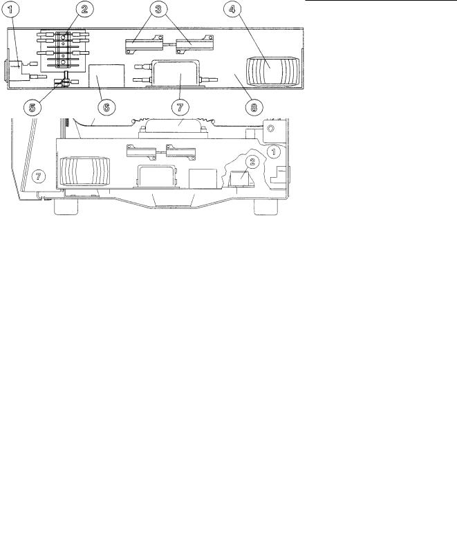
FIG. 2.3 - COMPONENTS OF THE C3i |
||
1. |
Power supply rack |
5. |
Lid lock solenoid |
2. |
Imbalance sensor |
6. |
Display assembly and keyboard |
3. |
Induction motor |
7. |
Microprocessor/power pcb |
4. |
Centrifugation chamber bowl |
8. |
Gas spring |
|
|
FIG. 2.4 - POWER SUPPLY RACK C3i |
|
1. |
Main socket and fuse carrier |
5. |
Ground/Earth |
2. |
Fast-on connection strip |
6. |
Motor earthing reactor |
3. |
Braking resistance |
7. |
Mains filter |
4. |
DC tranformer |
8. |
Rack |
C3i-M

2 - 5
|
|
FIG. 2.5 - COMPONENTS OF THE CR3i |
|
1. |
Cooling fan /condenser |
5. |
Lid lock solenoid |
2. |
Imbalance sensor |
6. |
Display assembly keyboard |
3. |
Induction motor |
7. |
Microprocessor/power pcb |
4. |
Compressor |
|
|
1. Mains socket
2. Compressor pcb
3. Braking resistances
4. Transformer
5. Ground/ earth
6. Motor earthing reactor
7. Mains filter
8. Rack
FIG. 2.6 - POWER SUPPLY RACK CR3i
C3i-M

2 - 6
2.3. MOTOR CONTROL PRINCIPLE
2.3.1.INTRODUCTION
The C3i / C R 3 i family of centrifuges is fitted with an asynchronous 3 phase motor. During the centrifugation, the microprocessor generates a system of sinusoidal 3 phase voltages, variable in amplitude and frequencies. During the braking phase the energy from the rotating parts is commuted across a resistance.
2.3.2.THE MOTOR
The motor comprises a 3 phase stator and a short-circuited rotor.
When correctly powered, the stator creates a magnetic field rotating at the synchronised speed Ns : Ns = F/p
F : supply frequency
P : number of pairs of poles of the motor
The rotating field generated in the motor induces e.m.f.'s. These e.m.f.'s produce currents in the short circuited rotor.
These induced currents found in the magnetic field create forces opposed to those which induced them.
It is the relative speed between the rotor and stator which is the cause of these induced currents, thus the forces will reduce this relative speed by driving the rotor at a speed close to that of the field created at the stator.
The difference (s) between the synchronised speed Ns and the actual speed N of the rotor is called the slippage.
s = Ns - N Ns
At a given frequency, the slippage value depends on the resisting torque (i.e. that of the rotor).
C3i-M
2 - 7
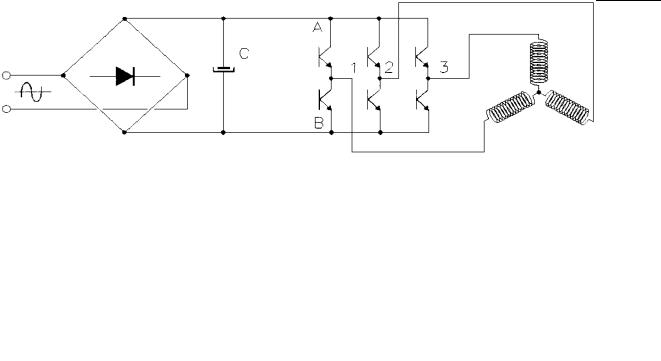
2.3.3.POWER CONTROL
Three voltages, variable in amplitude and frequency, dephased by 2π/3, must be supplied from a 50 or 60 Hz single phase mains supply.
V MAINS
STATOR
The voltage is rectified then filtered by C to supply the constant voltage +E. The value of the capacitor C is high.
The 6 transistors act as switches (open or closed).
These transistors commute at a fixed frequency (8 kHz).
To affect the voltage at R we act upon the commands of the transistors a and b, b always being the opposite to a (a = closed, b = open). By changing the cyclic ratio (closed/open) we obtain a mean sinusoidal value so we are able to vary the amplitude and frequency.
It is necessary that the pilot frequency must be elevated compared to the frequency of the generated sinusoidal voltage. The latter is around 400 Hz at 24000 r.p.m. (f pilot / f sin = 10 at N max. speed).
In the same way, the voltages at points S and T will be sinusoidal between OV and +E and dephased by 2π/3 between them.
These 3 voltages are simple voltages varying between OV and +E. They are partly sinusoidal and partly on a baseline situated at +E/2. Thus the O of the sinusoidal voltage corresponds to 50 % of the cyclic ratio.
The voltages applied to the motor phases are the compound voltages VR-VS, VS-VT,VT-VR and will vary between + E and - E ([O-(+E) = -E]
Thus at the motor terminals are recreated the voltages whose amplitude is close to that of the mains.
C3i-M

2 - 8
Speed synchronisation is directly proportional to the frequency of the voltage supplied to the motor. Ns = f x 60 (for a 2 pole motor).
The motor rotates at a speed N below the speed Ns.
Ns - N |
= SLIPPAGE (the slippage varies between 1 and 3%). |
|
Ns |
||
|
To vary the speed, it is necessary to vary Ns and thus the frequency of the voltage supplied to the motor.
The torque characteristics will be translated on the speed axis. The supply voltage will vary within 0 to 12000 r.p.m. in order to keep the U/f ratio constant and not saturate the magnetic circuit.
C Max
Torque
Operating point
torque Motor
Resistant |
torque |
|
Speed
FIG. 2.7 - VARIATION OF THE CURVE OF THE MOTOR TORQUE AS A FUNCTION OF THE SPEED
2.4. ELECTRONICS - STRUCTURE
2.4.1. INTRODUCTION
The electronic part of the apparatus is formed of two boards : the microprocessor + power pcb, where every function is located and the user interface pcb with display and LEDs. The former is located inside the body of the machine (fig. 2.3 or 2.5, item 7), whereas the second one is in the back of the front panel (fig. 2.3 or 2.5, item 6).
The electronic imbalance sensor is located on the motor stabilizer (fig. 2.3 or 2.5, item 2) and allows the detection of and excessive imbalance due to the rotor loading.
C3i-M

2 - 9
2.4.2.MICROPROCESSOR + POWER PCB
On the microprocessor + power pcb, 3 distinct zones can be identified, whose functions are described below. Each zone has its own independent power supply.
ZONE 1 :
This zone includes the microprocessor, the EPROM containing the software and the non-volatile RAM containing the program parameters. The set of components in this zone is at the potential of the microprocessor : 5 VDC.
ZONE 2 :
This zone ensures the conformity of the signal type coming from the different detectors before their arrival at the microcontroller via opto couplers.
It also monitors the lid lock control and refrigeration group commands.
The power supply for this zone is 12 VDC.
The different signals coming to this zone are :
-Bowl temperature.
-Signal coming from the imbalance sensor
-Tacho signal
-Lid position signal
-The motor overtemperature and the lid lock solenoid control.
C3i-M
 Loading...