

Page 1

CENTRIFUGE
C3i /CR3i
SERVICE MANUAL
Page 2

CAREFULLY READ THIS MANUAL BEFORE OPERATING YOUR INSTRUMENT.
INFORMATION CONTAINED IN THIS DOCUMENT IS THE PROPERTY OF JOUAN ;
IT MAY NOT BE DUPLICATED OR DISTRIBUTED WITHOUT THE OWNER’S AUTHORIZATION.
CENTRIFUGE
C3i /CR3i
SERVICE MANUAL
89000832-a
Page 3

C3i-M
REVISION STATUS
INDEX DATE AMENDED PAGES NOTES
a 03/98 Initial release
Page 4

C3i-M
WARRANTY
Subject to the due observance of any installation, operating or maintenance instructions, we warrant that we will
at our option replace, or repair free of charge, or credit the purchaser with the full invoice price of any goods or
parts of goods of our own manufacture proved to be defective owing to faulty workmanship or materials,
provided that we are notified in writing of the alleged defect within 12 months of the date of despatch of the
goods and the goods are returned to us promptly on discovery of the alleged defect with details of the manner
and circumstances in which they are alleged to have become defective.
Replaced goods become our property.
Goods not manufactured by us are only guaranteed to the guarantee given to us by the actual manufacturers.
Our obligations in respect of defective goods set out above are exclusive and expressly in lieu of all other terms,
warranties and conditions, expressed or implied (including without prejudice to the generality of the foregoing)
warranties and conditions or merchantability and fitness for a particular purpose all of which terms warranties
and conditions are hereby expressly excluded.
It is a condition of sale that the purchaser agrees to keep us indemnified at all times in respect of all actions
proceedings, claims and demands whatsoever which may be made by any third party against us for any loss or
damage howsoever arising (including with prejudice to the generality of the foregoing loss or damage arising
out of the negligence of our employees or agents) which may be caused by goods sold to the purchaser, and all
costs and expenses incurred by us in connection therewith.
All liability for loss of profit, consequential loss, or any other loss whatsoever suffered by the purchaser
howsoever arising (including without prejudice to the generality of the foregoing loss arising out of our
negligence of our servants or agents) is hereby expressly excluded.
In the event that purchaser makes any claims for such or any loss or damage against any of our employees or
agents, it shall pay to us the amount (if any) recovered from such employee or agent and an amount equal to the
legal costs (on a full indemnity basis) incurred by such employee or agent in defending or compromising the
purchaser's claim).
Page 5

C3i-M
CHAPTER 1 - INTRODUCTION . . . . . . . . . . . . . . . . . . . . . . . . . . . . . . . . . . . . . . . . . . . . . . . . . . . . . . . . . . . . 1-1
1.1. Purpose . . . . . . . . . . . . . . . . . . . . . . . . . . . . . . . . . . . . . . . . . . . . . . . . . . . . . . . . . . . . . . . . . . . . . . . . . . . . . . . 1-1
1.2. Presentation . . . . . . . . . . . . . . . . . . . . . . . . . . . . . . . . . . . . . . . . . . . . . . . . . . . . . . . . . . . . . . . . . . . . . . . . . . . 1-1
1.3. Specifications . . . . . . . . . . . . . . . . . . . . . . . . . . . . . . . . . . . . . . . . . . . . . . . . . . . . . . . . . . . . . . . . . . . . . . . . . . 1-2
1.3.1. Dimensions and weight . . . . . . . . . . . . . . . . . . . . . . . . . . . . . . . . . . . . . . . . . . . . . . . . . . . . . . . . . . . 1-2
1.3.2. Electrical specifications . . . . . . . . . . . . . . . . . . . . . . . . . . . . . . . . . . . . . . . . . . . . . . . . . . . . . . . . . . 1-2
1.3.3. Performance . . . . . . . . . . . . . . . . . . . . . . . . . . . . . . . . . . . . . . . . . . . . . . . . . . . . . . . . . . . . . . . . . . . . 1-2
1.4. Installation procedure . . . . . . . . . . . . . . . . . . . . . . . . . . . . . . . . . . . . . . . . . . . . . . . . . . . . . . . . . . . . . . . . . . . 1-3
CHAPTER 2 - THEORY OF OPERATION . . . . . . . . . . . . . . . . . . . . . . . . . . . . . . . . . . . . . . . . . . . . . . . . . . . . . 2-1
2.1. Description . . . . . . . . . . . . . . . . . . . . . . . . . . . . . . . . . . . . . . . . . . . . . . . . . . . . . . . . . . . . . . . . . . . . . . . . . . . . 2-1
2.2. Component lay-out . . . . . . . . . . . . . . . . . . . . . . . . . . . . . . . . . . . . . . . . . . . . . . . . . . . . . . . . . . . . . . . . . . . . . 2-1
2.3. Motor control principle . . . . . . . . . . . . . . . . . . . . . . . . . . . . . . . . . . . . . . . . . . . . . . . . . . . . . . . . . . . . . . . . . . 2-6
2.3.1. Introduction . . . . . . . . . . . . . . . . . . . . . . . . . . . . . . . . . . . . . . . . . . . . . . . . . . . . . . . . . . . . . . . . . . . . 2-6
2.3.2. The motor . . . . . . . . . . . . . . . . . . . . . . . . . . . . . . . . . . . . . . . . . . . . . . . . . . . . . . . . . . . . . . . . . . . . . . 2-6
2.3.3. Power control . . . . . . . . . . . . . . . . . . . . . . . . . . . . . . . . . . . . . . . . . . . . . . . . . . . . . . . . . . . . . . . . . . . 2-7
2.4. Electronics - structure . . . . . . . . . . . . . . . . . . . . . . . . . . . . . . . . . . . . . . . . . . . . . . . . . . . . . . . . . . . . . . . . . . . 2-8
2.4.1. Introduction . . . . . . . . . . . . . . . . . . . . . . . . . . . . . . . . . . . . . . . . . . . . . . . . . . . . . . . . . . . . . . . . . . . . 2-8
2.4.2. Microprocessor + power pcb . . . . . . . . . . . . . . . . . . . . . . . . . . . . . . . . . . . . . . . . . . . . . . . . . . . . . 2-9
2.4.3. Imbalance sensor . . . . . . . . . . . . . . . . . . . . . . . . . . . . . . . . . . . . . . . . . . . . . . . . . . . . . . . . . . . . . . . 2-10
2.4.4. Tacho sensor . . . . . . . . . . . . . . . . . . . . . . . . . . . . . . . . . . . . . . . . . . . . . . . . . . . . . . . . . . . . . . . . . . . 2-10
2.4.5. Temperature sensor (CR3i) . . . . . . . . . . . . . . . . . . . . . . . . . . . . . . . . . . . . . . . . . . . . . . . . . . . . . . . 2-10
2.4.6. Refrigeration control board (CR3i) . . . . . . . . . . . . . . . . . . . . . . . . . . . . . . . . . . . . . . . . . . . . . . . . . 2-10
2.4.7. Input - output . . . . . . . . . . . . . . . . . . . . . . . . . . . . . . . . . . . . . . . . . . . . . . . . . . . . . . . . . . . . . . . . . . . . 2-11
CHAPTER 3 - DIAGNOSTICS AND REPAIRS . . . . . . . . . . . . . . . . . . . . . . . . . . . . . . . . . . . . . . . . . . . . . . . . . . 3-1
3.1. Introduction . . . . . . . . . . . . . . . . . . . . . . . . . . . . . . . . . . . . . . . . . . . . . . . . . . . . . . . . . . . . . . . . . . . . . . . . . . . 3-1
3.2. Functional test . . . . . . . . . . . . . . . . . . . . . . . . . . . . . . . . . . . . . . . . . . . . . . . . . . . . . . . . . . . . . . . . . . . . . . . . . 3-1
3.2.1. EPROM version . . . . . . . . . . . . . . . . . . . . . . . . . . . . . . . . . . . . . . . . . . . . . . . . . . . . . . . . . . . . . . . . . 3-1
3.2.2. Test mode . . . . . . . . . . . . . . . . . . . . . . . . . . . . . . . . . . . . . . . . . . . . . . . . . . . . . . . . . . . . . . . . . . . . . . 3-1
3.3. Fault codes . . . . . . . . . . . . . . . . . . . . . . . . . . . . . . . . . . . . . . . . . . . . . . . . . . . . . . . . . . . . . . . . . . . . . . . . . . . . 3-5
3.4. Troubleshooting chart . . . . . . . . . . . . . . . . . . . . . . . . . . . . . . . . . . . . . . . . . . . . . . . . . . . . . . . . . . . . . . . . . . . 3-6
CHAPTER 4 - REPLACEMENT PROCEDURES . . . . . . . . . . . . . . . . . . . . . . . . . . . . . . . . . . . . . . . . . . . . . . . . 4-1
4.1. Motor replacement . . . . . . . . . . . . . . . . . . . . . . . . . . . . . . . . . . . . . . . . . . . . . . . . . . . . . . . . . . . . . . . . . . . . . 4-1
4.1.1. Unrefrigerated model (C3i) . . . . . . . . . . . . . . . . . . . . . . . . . . . . . . . . . . . . . . . . . . . . . . . . . . . . . . . 4-1
4.1.2. Refrigerated model (CR3i) . . . . . . . . . . . . . . . . . . . . . . . . . . . . . . . . . . . . . . . . . . . . . . . . . . . . . . . . 4-2
4.2. Imbalance detector replacement . . . . . . . . . . . . . . . . . . . . . . . . . . . . . . . . . . . . . . . . . . . . . . . . . . . . . . . . . 4-3
4.3. Replacement of the lid lock assembly . . . . . . . . . . . . . . . . . . . . . . . . . . . . . . . . . . . . . . . . . . . . . . . . . . . . . . 4-3
4.4. Lid lock assembly element replacement . . . . . . . . . . . . . . . . . . . . . . . . . . . . . . . . . . . . . . . . . . . . . . . . . . . 4-4
4.4.1. Lid lock microswitch replacement . . . . . . . . . . . . . . . . . . . . . . . . . . . . . . . . . . . . . . . . . . . . . . . . . 4-4
4.4.2. Lid lock replacement . . . . . . . . . . . . . . . . . . . . . . . . . . . . . . . . . . . . . . . . . . . . . . . . . . . . . . . . . . . . 4-4
4.4.3. Lock solenoid microswitch replacement . . . . . . . . . . . . . . . . . . . . . . . . . . . . . . . . . . . . . . . . . . . . 4-4
4.4.4. Solenoid replacement . . . . . . . . . . . . . . . . . . . . . . . . . . . . . . . . . . . . . . . . . . . . . . . . . . . . . . . . . . . . 4-5
4.5. Power supply rack replacement . . . . . . . . . . . . . . . . . . . . . . . . . . . . . . . . . . . . . . . . . . . . . . . . . . . . . . . . . . 4-5
4.5.1. Rack replacement for the C3i . . . . . . . . . . . . . . . . . . . . . . . . . . . . . . . . . . . . . . . . . . . . . . . . . . . . . 4-5
4.5.2. Rack replacement for the CR3i . . . . . . . . . . . . . . . . . . . . . . . . . . . . . . . . . . . . . . . . . . . . . . . . . . . . 4-6
4.5.3. Refrigeration board replacement (CR3i) . . . . . . . . . . . . . . . . . . . . . . . . . . . . . . . . . . . . . . . . . . . . . 4-6
CONTENTS
Page 6

C3i-M
4.6. Electronic board replacement . . . . . . . . . . . . . . . . . . . . . . . . . . . . . . . . . . . . . . . . . . . . . . . . . . . . . . . . . . . . 4-7
4.6.1. Microprocessor + power pcb . . . . . . . . . . . . . . . . . . . . . . . . . . . . . . . . . . . . . . . . . . . . . . . . . . . . . 4-7
4.6.2. Display board . . . . . . . . . . . . . . . . . . . . . . . . . . . . . . . . . . . . . . . . . . . . . . . . . . . . . . . . . . . . . . . . . . . 4-8
4.7. Keyboard replacement . . . . . . . . . . . . . . . . . . . . . . . . . . . . . . . . . . . . . . . . . . . . . . . . . . . . . . . . . . . . . . . . . 4-8
4.8. Gas spring replacement . . . . . . . . . . . . . . . . . . . . . . . . . . . . . . . . . . . . . . . . . . . . . . . . . . . . . . . . . . . . . . . . . 4-8
4.8.1. Gas spring replacement on the C3i . . . . . . . . . . . . . . . . . . . . . . . . . . . . . . . . . . . . . . . . . . . . . . . . 4-8
4.8.2. Gas spring replacement on the CR3i . . . . . . . . . . . . . . . . . . . . . . . . . . . . . . . . . . . . . . . . . . . . . . . 4-9
4.9. Tacho replacement . . . . . . . . . . . . . . . . . . . . . . . . . . . . . . . . . . . . . . . . . . . . . . . . . . . . . . . . . . . . . . . . . . . . . 4-9
4.10. EPROM replacement . . . . . . . . . . . . . . . . . . . . . . . . . . . . . . . . . . . . . . . . . . . . . . . . . . . . . . . . . . . . . . . . . . . . 4-10
4.11. Lid replacement . . . . . . . . . . . . . . . . . . . . . . . . . . . . . . . . . . . . . . . . . . . . . . . . . . . . . . . . . . . . . . . . . . . . . . . . 4-10
4.12. Refrigeration group repairs (CR3i) . . . . . . . . . . . . . . . . . . . . . . . . . . . . . . . . . . . . . . . . . . . . . . . . . . . . . . . . 4-11
4.12.1. Refrigeration group replacement . . . . . . . . . . . . . . . . . . . . . . . . . . . . . . . . . . . . . . . . . . . . . . . . . . . 4-11
4.12.2. Condenser components replacement . . . . . . . . . . . . . . . . . . . . . . . . . . . . . . . . . . . . . . . . . . . . . . . 4-12
4.13 Motor checking . . . . . . . . . . . . . . . . . . . . . . . . . . . . . . . . . . . . . . . . . . . . . . . . . . . . . . . . . . . . . . . . . . . . . . . . 4-12
4.14 Checking and maintenance of the centering group . . . . . . . . . . . . . . . . . . . . . . . . . . . . . . . . . . . . . . . . . . 4-13
CHAPTER 5 - CHECKS, ADJUSTMENTS, CALIBRATION . . . . . . . . . . . . . . . . . . . . . . . . . . . . . . . . . . . . . . . . 5-1
5.1. Imbalance adjustment . . . . . . . . . . . . . . . . . . . . . . . . . . . . . . . . . . . . . . . . . . . . . . . . . . . . . . . . . . . . . . . . . . 5-1
5.2. Temperature sensor calibration (CR3i) . . . . . . . . . . . . . . . . . . . . . . . . . . . . . . . . . . . . . . . . . . . . . . . . . . . . . 5-2
CHAPTER 6 - SPARE PARTS - DIAGRAMS . . . . . . . . . . . . . . . . . . . . . . . . . . . . . . . . . . . . . . . . . . . . . . . . . . . . 6.1
6.1. General . . . . . . . . . . . . . . . . . . . . . . . . . . . . . . . . . . . . . . . . . . . . . . . . . . . . . . . . . . . . . . . . . . . . . . . . . . . . . . . 6-1
6.2. Motor . . . . . . . . . . . . . . . . . . . . . . . . . . . . . . . . . . . . . . . . . . . . . . . . . . . . . . . . . . . . . . . . . . . . . . . . . . . . . . . 6-2
6.3. AUTO-LOCK system . . . . . . . . . . . . . . . . . . . . . . . . . . . . . . . . . . . . . . . . . . . . . . . . . . . . . . . . . . . . . . . . . . . . 6-3
6.4. Lock . . . . . . . . . . . . . . . . . . . . . . . . . . . . . . . . . . . . . . . . . . . . . . . . . . . . . . . . . . . . . . . . . . . . . . . . . . . . . . . 6-4
6.5. Feeder group . . . . . . . . . . . . . . . . . . . . . . . . . . . . . . . . . . . . . . . . . . . . . . . . . . . . . . . . . . . . . . . . . . . . . . . . . . 6-5
6.6. Refrigeration group (CR3i) . . . . . . . . . . . . . . . . . . . . . . . . . . . . . . . . . . . . . . . . . . . . . . . . . . . . . . . . . . . . . . . 6-6
6.7. Condenser group (CR3i) . . . . . . . . . . . . . . . . . . . . . . . . . . . . . . . . . . . . . . . . . . . . . . . . . . . . . . . . . . . . . . . . 6-7
APPENDIX A - RECOMMENDED LIST OF TOOLS . . . . . . . . . . . . . . . . . . . . . . . . . . . . . . . . . . . . . . . . . . . . . A-1
APPENDIX B - ELECTRICAL DIAGRAMS . . . . . . . . . . . . . . . . . . . . . . . . . . . . . . . . . . . . . . . . . . . . . . . . . . . . B-1
Page 7

C3i-M
1 - 1
1.1. PURPOSE
This manual contains maintenance instructions intended for use by a qualified maintenance or service
technician. It is organized to provide maintenance personnel with basic data on the theory of operation to
assist in troubleshooting. Moreover, it outlines parts replacement and calibration procedures for putting
the centrifuges back into service.
Should a specific maintenance problem arise which is not covered in this manual, please ask the
authorized service organization in your area for assistance, or contact our after sales department :
JOUAN SA
AFTER SALES SERVICE
C.P. 3203, 44805 SAINT-HERBLAIN CEDEX - FRANCE
Tel. +33 (0) 2 40 16 80 00 - Fax : +33 (0) 2 40 94 70 16
Telex : 711062 JOUAN NT
JOUAN LTD JOUAN GmbH
Merlin Way, Quarry Hill Road Kapellenstrasse 22
ILKESTON, DERBYS, DE7 4RA - U.K. 82008 UNTERHACHING - GERMANY
Tel. (0115) 944 7989 Tel. : (089) 611 4038
Fax : (0115) 944 7080 Fax : (089) 611 3087
JOUAN INC.
Delivery address : 110-B Industrial Drive, WINCHESTER, VA 22602 - U.S.A
Postal address : P.O. Box 2716, WINCHESTER, VA 22604-9879 - U.S.A
Tel. (540) 869 8623 - Fax : (540) 869 8626 - Toll free : (800) 662 7477
1.2. PRESENTATION
The C3i and CR3i (refrigerated) centrifuges are instruments designed for laboratory use. Using relative
centrifuge force (RCF) allows elements of different density to be separated.
The rotor is the main load; a swing-out design allows a higher load than does an angle design. The larger
the rotor diameter is, the higher the load can be and thus the slower the speed will be.
The RCF is directly proportional to the radius of sedimentation and to the square of the speed.
The gas used in the refrigeration system (CR3
i) is R134a, without CFC, recommended by the directive for
protection of the ozone layer.
1 INTRODUCTION
Page 8

C3i-M
1 - 2
1.3. SPECIFICATIONS
1.3.1. DIMENSIONS AND WEIGHT
Dimensions (H x W x D) C3i : 372 x 400 x 495 mm CR3i : 375 x 575 x 605 mm
Packed (H x W x D) C3i : 600 x 610 x 540 mm CR3i : 590 x 720 x 710 mm
Weight - uncrated / crated C3i : 40 kg / 52 kg CR3i : 72 kg / 85 kg
1.3.2. ELECTRICAL SPECIFICATIONS
Mains supply 220/240 VAC 50 Hz C3i : 11175700 CR3i : 11175703
Mains supply 120 VAC 60 Hz C3i : 11175701 CR3i : 11175704
Max power C3i : 500 W CR3i : 800 W
Average power C3i : 350 W CR3i : 550 W
Refrigeration CR3i : 235 W
1.3.3. PERFORMANCE
Max speed Swing-out : 4 000 rpm (C3i) Angle : 14 000 rpm
Swing-out : 4 100 rpm (CR3i)
Max RCF Swing-out : 3 934 x g (C3i) Angle : 18 407 x g
Swing-out : 3 082 rpm (CR3i)
Max capacity Swing-out : 4 x 280 ml Angle : 6 x 100 ml
Microprocessor controlled
Display High visibility digital display
Memory size 5 programs, direct access
Program protection Recall key lock
Speed Range 500 to 14 000 rpm
Step 10 -100 rpm
Accuracy ± 20 rpm
Timer Range 30 sec to 99 min + hold position
Step 30 sec to 1 min
Acceleration rates 5
Braking rates 5
Temperature (CR3
i) Range -9°C to +40°C
Step 1°C
Accuracy ± 1.5°C
Typical performance 4°C at 4 000 rpm, (4 x 280 ml swing-out)
1°C at 14 000 rpm, (20 x 1.5 ml angle)
Maximum density 1.2 g/cm
3
Maximum energy 14 400 J
Page 9
C3i-M
1 - 3
1.4. INSTALLATION PROCEDURE
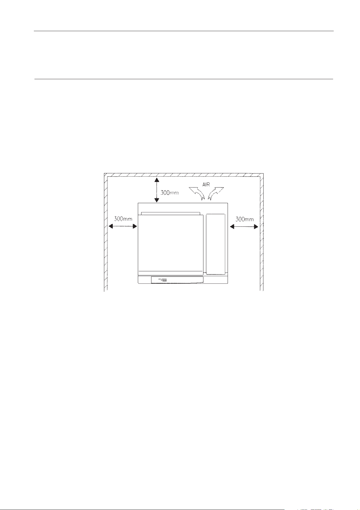
The environment must not be in a dusty room or corrosive environment.
The bench top must be of a rigid construction capable of supporting the weight of the centrifuge.
IMPORTANT : at least two people are required to lift the centrifuge from the palette and place it on the
bench.
WARNING : The rear panel of the instrument must be at least 30 cm from the walls to allows hot air coming
from the condenser to escape.
Page 10

C3i-M
2 - 1
2.1. DESCRIPTION
The microprocessor system which controls the C3i or CR3i centrifuges ensures the operation of the
following major elements :
- Management of the operating modes
- Generation of alternating current amplitude and frequency
- Adjustable components for the motor speed servo
- Management of the acceleration and braking profile/rates
- Management of the temperature regulation (CR3
i)
- Management of the safety devices :
.
Lid lock
.
Zero speed detection
.
Imbalance detection
.
Motor overtemperature detection.
- Management of fault diagnosis.
2.2. COMPONENT LAY-OUT
The inpout and control devices are located on the front panel and comprise a membrane keyboard and
three digital displays.
Everything is controlled by a 16 bit microprocessor. The control program of the centrifuge is stored in an
EPROM.
Data are conveyed into a dynamic RAM and are kept even when the power is down, thanks to an internal
battery, which supplies power.
2 THEORY OF OPERATION
Page 11
C3i-M
2 - 2
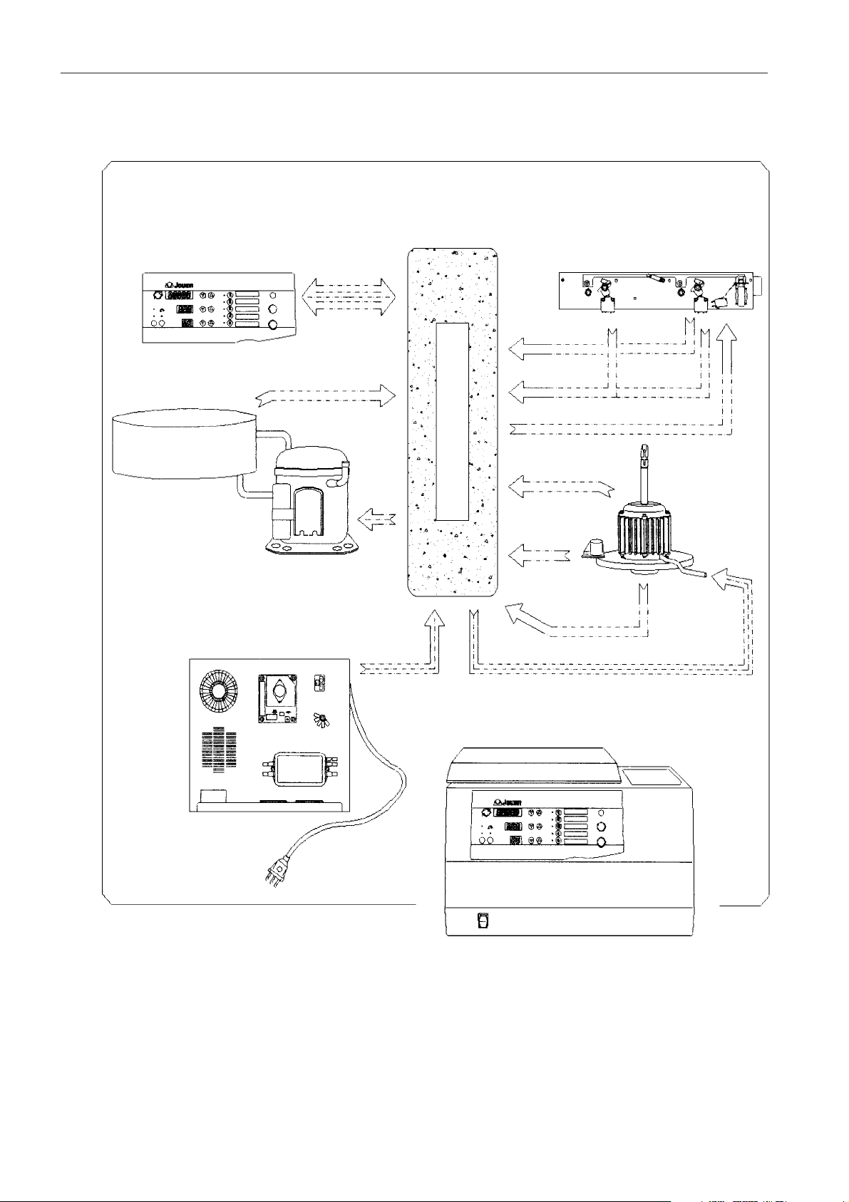
FIG. 2.1 - CR3i FUNCTIONAL PRESENTATION
FLEXIBLE KEYBOARD
AND DISPLAY
USER
INTERFACE
TEMPERATURE (CR3i)
COMPRESSOR (CR3i)
BOWL (CR3i)
POWER RACK AND
FILTERS
MOTOR SUPPLY
SPEED
IMBALANCE
MOTOR
TEMPERATURE
SWITCH
SWITCH
SOLENOID
LOCK ASSEMBLY
CONTROL
SYSTEM
Page 12
C3i-M
2 - 3
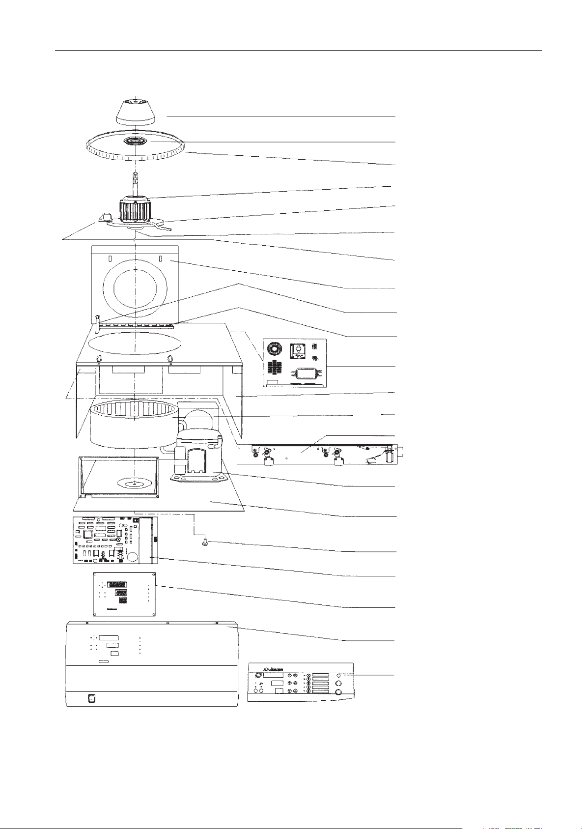
ROTOR
MOTOR CHAMBER SEAL
LID/BOWL SEAL
MOTOR
STABILIZER
SUSPENSION
IMBALANCE SENSOR
LID
GAS SPRING
LID HINGE
POWER INPUT RACK
CENTRIGUGE BODY
CENTRIFUGE BOWL
LOCKING SYSTEM
COMPRESSOR (CR3i)
FRAME
MOTOR FIXING BOLTS
MICROPROCESSOR + POWER
PCB
DISPLAY ASSEMBLY
FRONT PANEL
KEYBOARD
FIG. 2.2 - CR3i EXPLODED VIEW
Page 13
C3i-M
2 - 4
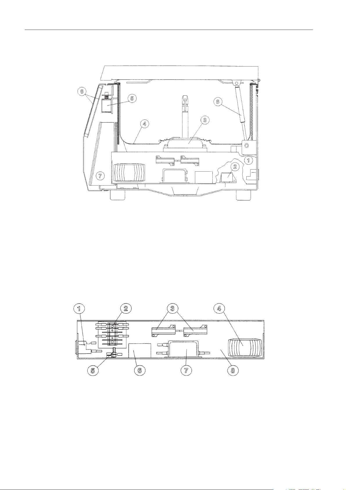
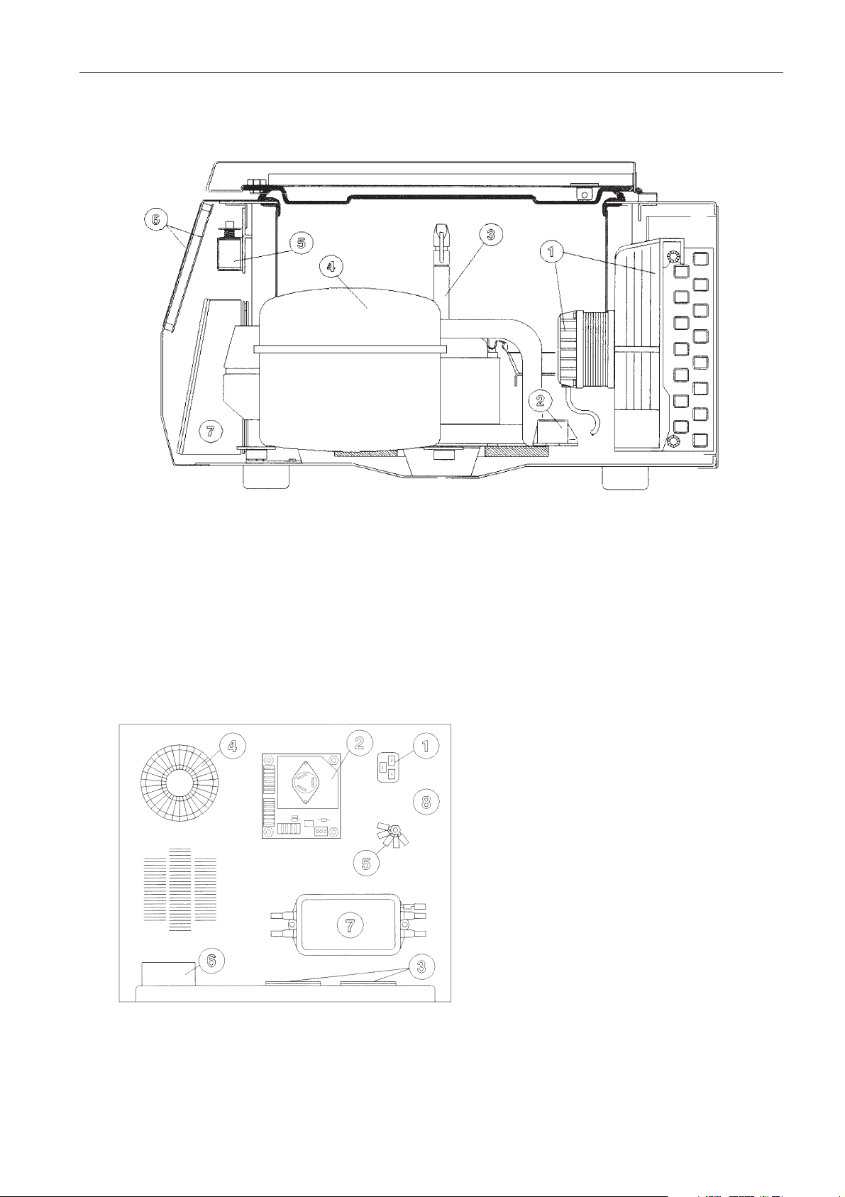
FIG. 2.3 - COMPONENTS OF THE C3i
1. Power supply rack
2. Imbalance sensor
3. Induction motor
4. Centrifugation chamber bowl
5. Lid lock solenoid
6. Display assembly and keyboard
7. Microprocessor/power pcb
8. Gas spring
1. Main socket and fuse carrier
2. Fast-on connection strip
3. Braking resistance
4. DC tranformer
5. Ground/Earth
6. Motor earthing reactor
7. Mains filter
8. Rack
FIG. 2.4 - POWER SUPPLY RACK C3i
Page 14
C3i-M
2 - 5
FIG. 2.5 - COMPONENTS OF THE CR3i
1. Cooling fan /condenser
2. Imbalance sensor
3. Induction motor
4. Compressor
5. Lid lock solenoid
6. Display assembly keyboard
7. Microprocessor/power pcb
FIG. 2.6 - POWER SUPPLY RACK CR3i
1. Mains socket
2. Compressor pcb
3. Braking resistances
4. Transformer
5. Ground/ earth
6. Motor earthing reactor
7. Mains filter
8. Rack
Page 15

C3i-M
2 - 6
2.3. MOTOR CONTROL PRINCIPLE
2.3.1. INTRODUCTION
The C3i /CR3i family of centrifuges is fitted with an asynchronous 3 phase motor. During the
centrifugation, the microprocessor generates a system of sinusoidal 3 phase voltages, variable in
amplitude and frequencies. During the braking phase the energy from the rotating parts is commuted
across a resistance.
2.3.2. THE MOTOR
The motor comprises a 3 phase stator and a short-circuited rotor.
When correctly powered, the stator creates a magnetic field rotating at the synchronised speed Ns :
Ns = F/p
F : supply frequency
P : number of pairs of poles of the motor
The rotating field generated in the motor induces e.m.f.'s. These e.m.f.'s produce currents in the short
circuited rotor.
These induced currents found in the magnetic field create forces opposed to those which induced them.
It is the relative speed between the rotor and stator which is the cause of these induced currents, thus the
forces will reduce this relative speed by driving the rotor at a speed close to that of the field created at the
stator.
The difference (s) between the synchronised speed Ns and the actual speed N of the rotor is called the
slippage.
s = N
s -N
Ns
At a given frequency, the slippage value depends on the resisting torque (i.e. that of the rotor).
Page 16
C3i-M
2 - 7
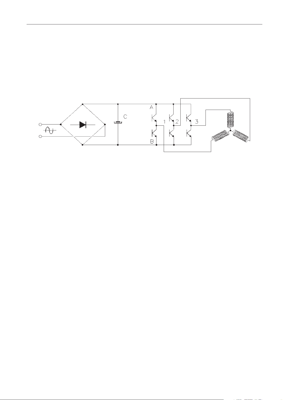
The voltage is rectified then filtered by C to supply the constant voltage +E. The value of the capacitor C is
high.
The 6 transistors act as switches (open or closed).
These transistors commute at a fixed frequency (8 kHz).
To affect the voltage at R we act upon the commands of the transistors a and b, b always being the
opposite to a (a = closed, b = open). By changing the cyclic ratio (closed/open) we obtain a mean
sinusoidal value so we are able to vary the amplitude and frequency.
It is necessary that the pilot frequency must be elevated compared to the frequency of the generated
sinusoidal voltage. The latter is around 400 Hz at 24000 r.p.m. (f pilot / f sin = 10 at N max. speed).
In the same way, the voltages at points S and T will be sinusoidal between OV and +E and dephased by
2π/3 between them.
These 3 voltages are simple voltages varying between OV and +E. They are partly sinusoidal and partly
on a baseline situated at +E/2. Thus the O of the sinusoidal voltage corresponds to 50 % of the cyclic ratio.
The voltages applied to the motor phases are the compound voltages VR-VS, VS-VT,VT-VR and will vary
between + E and - E ([O-(+E) = -E]
Thus at the motor terminals are recreated the voltages whose amplitude is close to that of the mains.
2.3.3. POWER CONTROL
Three voltages, variable in amplitude and frequency, dephased by 2π/3, must be supplied from a 50 or
60 Hz single phase mains supply.
V MAINS
STATOR
Page 17
C3i-M
2 - 8
2.4. ELECTRONICS - STRUCTURE
2.4.1. INTRODUCTION
The electronic part of the apparatus is formed of two boards : the microprocessor + power pcb, where
every function is located and the user interface pcb with display and LEDs. The former is located inside the
body of the machine (fig. 2.3 or 2.5, item 7), whereas the second one is in the back of the front panel (fig.
2.3 or 2.5, item 6).
The electronic imbalance sensor is located on the motor stabilizer (fig. 2.3 or 2.5, item 2) and allows the
detection of and excessive imbalance due to the rotor loading.
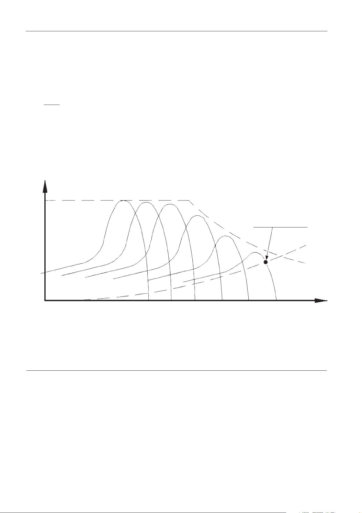
FIG. 2.7 - VARIATION OF THE CURVE OF THE MOTOR TORQUE AS A FUNCTION OF THE SPEED
C Max
Motor torque
Resistant torque
Torque
Operating point
Speed
Speed synchronisation is directly proportional to the frequency of the voltage supplied to the motor. Ns =
f x 60 (for a 2 pole motor).
The motor rotates at a speed N below the speed Ns.
Ns -N
Ns
= SLIPPAGE (the slippage varies between 1 and 3%).
To vary the speed, it is necessary to vary Ns and thus the frequency of the voltage supplied to the motor.
The torque characteristics will be translated on the speed axis. The supply voltage will vary within 0 to
12000 r.p.m. in order to keep the U/f ratio constant and not saturate the magnetic circuit.
Page 18
C3i-M
2 - 9
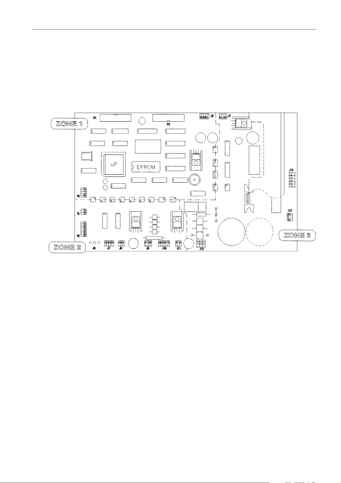
ZONE 1 :
This zone includes the microprocessor, the EPROM containing the software and the non-volatile RAM
containing the program parameters. The set of components in this zone is at the potential of the
microprocessor : 5 VDC.
ZONE 2 :
This zone ensures the conformity of the signal type coming from the different detectors before their arrival
at the microcontroller via opto couplers.
It also monitors the lid lock control and refrigeration group commands.
The power supply for this zone is 12 VDC.
The different signals coming to this zone are :
- Bowl temperature.
- Signal coming from the imbalance sensor
- Tacho signal
- Lid position signal
- The motor overtemperature and the lid lock solenoid control.
2.4.2. MICROPROCESSOR + POWER PCB
On the microprocessor + power pcb, 3 distinct zones can be identified, whose functions are described
below. Each zone has its own independent power supply.
Page 19

2 - 10
ZONE 3
WARNING ! THIS ZONE IS AT MAINS VOLTAGE
!
This zone isolated from the microprocessor part by opto-couplers, is the electronic part related to the
power in the system. This zone includes :
-The 15 VDC power supply for the control electronics for this zone.
-The control circuit of the 6 basic signals of the IGBT module.
-The 3 PWR commands coming from the microcontroller
-The brake GBT with the command which permits flow through the braking resistor.-
-The diode bridge which, from the mains, charge the capacitor of the continous bus
-The relay which, controlled by the supply of power, then short circuits the resistance of the charge of the
capacitors of the continuous bus a few moments after switch-on.
-The module of 6 IGBTs and its heat sink which power the motor.
2.4.3.IMBALANCE SENSOR
As described in the introduction, this sensor allows the detection of an excessive imbalance in the rotor
loading.
A piezzo ceramic converts the energy created by the vibration into an electrical signal. After shaping, this
signal is sent to the microprocessor for the safety devices.
2.4.4.TACHO SENSOR
The tacho sensor is comprised of an optical sensor, which, generates two pulses per revolution.
2.4.5.TEMPERATURE SENSOR (CR3i)
After the shaping circuit , the signal is 1.23 Vcc (0°C) ±80 mV/°C
2.4.6.REFRIGERATION CONTROL BOARD (CR3i)
The board controls the power signal to the refrigeration group.
C3i-M
Page 20
C3i-M
2 - 11
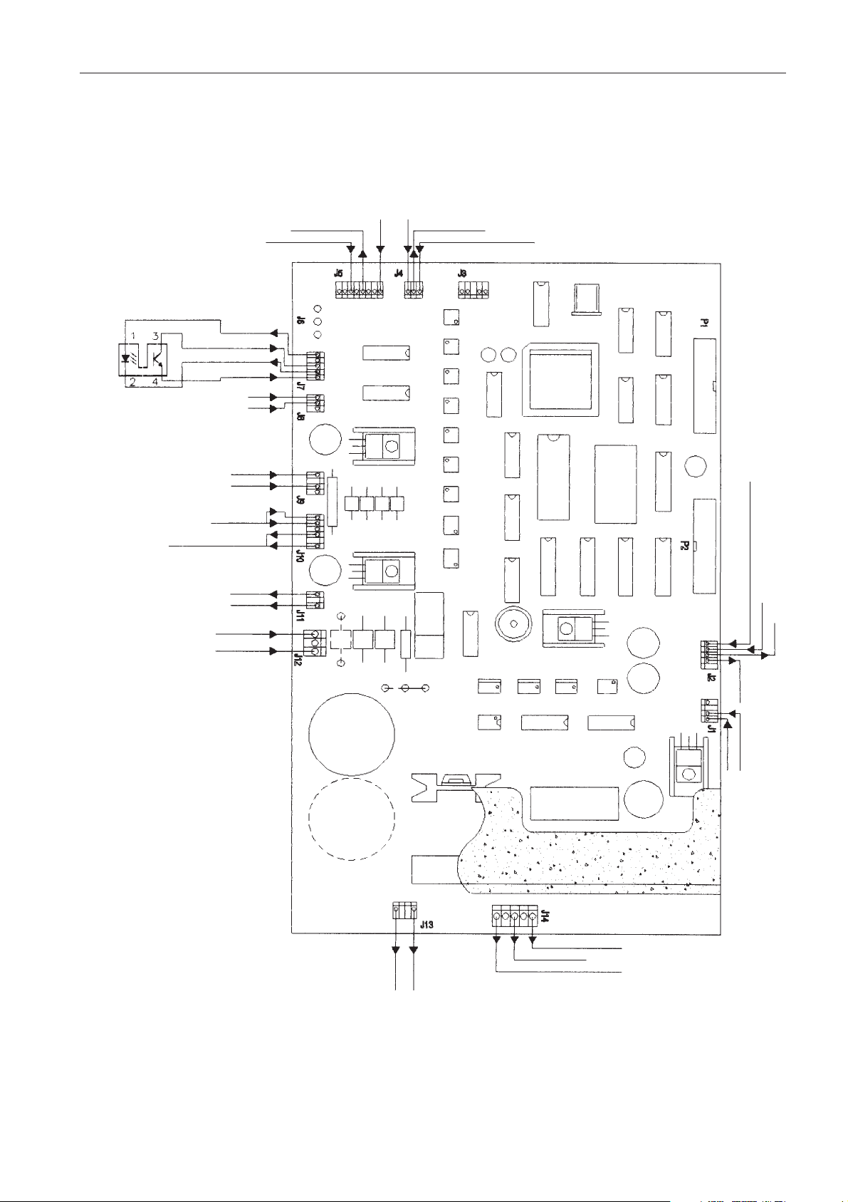
2.4.7. INPUT - OUTPUT
+12 V
PROBE (°C)
(CR3i)
GROUND/EARTH
IMBALANCE
OPTICAL TACHO
MOTOR OVERTEMP +
SOLENOID SWITCH
230 VAC INPUT
300 VDC BUS
300 V BUS
BRAKING
RESISTOR
MOTOR CONNECTION
24 VAC FOR 15 V REGUL
MOTOR CONTROL ZONE
13 VCC OUTPUT
FOR REGUL
5 V DISPLAY
9 VAC INPUT
FOR 5 V REGUL
MICRO ZONE
DISPLAYSKEYBOARD + LEDS
18 VAC
INPUT
LID
SWITCHES
SOLENOID
COMMAND
COOLING
ON/OFF
Page 21

C3i-M
3 - 1
3 DIAGNOSTICS AND REPAIRS
3.2.2. TEST MODE
This mode is accessible by using a combination of keys while the machine is setting up.
Press on the following two keys at the same time:
acceleration programming key braking programming key
3.1. INTRODUCTION
The C3i and CR3i are equipped with a diagnostic menu in order to help locate possible breakdowns. The
possible conditions of incorrect functioning are communicated to the user by means of error codes on the
display and buzzer alarms.
3.2. FUNCTIONAL TEST
Certain functional tests can be done directly using the keyboard and display.
These tests must only be undertaken by someone qualified to do so. They are protected by an access
code.
3.2.1. EPROM VERSION
The first message that appears when the machine is switched on remains active for a few seconds
(machine set up).
JOUAN
051
d
The word JOUAN appears, underneath which is a two figure number (in the
timer display) indicating the type of EPROM fitted to the centrifuge.
Example : 51 = C3i, 52 = CR3i
The EPROM index letter is identified on the temperature display.
Page 22

C3i-M
3 - 2
Test 1 : Temperature probe calibration and other tests
5 digit display : Actual speed
3 digit display : T-1 for test 1
2 digit display : actual temperature
Temperature calibration(CR3i) :
It is possible to calibrate the temperature measuring line by connecting pins 2 and 3 of the J5 connector on
the microprocessor/power pcb. To do this it is sufficient to displace J5 one pin higher.
In this case the temperature reading must be 37°C (to ±5°C before calibration).
Pressing simultaneously on the
▼▼▲▲ temperature programming keys calibrates the measuring line.
Display then shows 37°C.
It is then possible to “manually” adjust the temperature calibration coefficients by pressing on the key
corresponding to program 3. The following messages are displayed :
5 digit display : Temperature value read by the microprocessor
3 digit display Calibration coefficient value**
2 digit display Calculated temperature value**
** Flashing display of these parameters.
Using the ▼▼▲▲ time programming keys allows manual adjustment of the calibration coefficient.
Tachometer test
Turn the rotor by hand: the speed should appear on the 5 digit display.
Lid solenoid test
Press on the key corresponding to program 2 to power and/or release the solenoid.
Resetting of the 5 programs
Keep pressing on the key corresponding to program 4.
Complete program resetting on RAM
Press simultaneously on the ▲▲ speed programming key and the PULSE key to allow complete resetting of
the machine when it is next switched on.
- Press START to pass to the next test
- Press STOP to leave the test mode
00000
T-1
20
388
100
37
Page 23

C3i-M
3 - 3
Test 2 : Calibration of imbalance detection threshold
Standby and/or end of cycle :
Imbalance threshold
Pressing on PULSE begins a preprogrammed cycle at 2500 rpm during which the maximum imbalance is
recorded.
The set value is 350.
Using the
▼▼▲▲ time programming keys allows manual adjustment of the imbalance threshold.
During the cycle :
Actual rotating speed
Maximum imbalance reading
- Press START to pass to the next test
- Press STOP to leave the test mode
Test 3 : Run linking
This test safely used in the factory, starts a series of preset runs after having pressed the pulse key :
Run cycles of the selected program can be run with a one minute pause
between each.
Press ▼▼ and ▲▲ to change the number of runs from 1 to 99.
During a run, when rotating, displays are the same as they would be outside the test mode.
IMBAL
350
--
00000
000
--
CYCLE
---
6
Page 24

C3i-M
3 - 4
Between two runs (1 minute pause) displays are :
Counting down before the next run (seconds)
Next run number
- Press START key to go to the following test
- Press STOP key to exit from the test mode.
Test 4 : Statistical analysis
Press ▼▼ and ▲▲ to scroll on the 5 digit display
1 : running hours total (x 100)
2 : total number of runs
3 : number of hours above 5000 rpm
4 : number of runs above 5000 rpm
- Press START key to go back to test 1
- Press STOP key to exit from the test mode
CYCLE
059
2
STATS
---
0
Page 25

C3i-M
3 - 5
3.3. FAULT CODES
When certain faults are detected an audible alarm is switched on in addition to a code and a message.
According to the fault, the machine stops automatically under the conditions indicated in the following
table.
Code
ERR 1
ERR 2
ERR 3
ERR 4
CLOSE LID
ERR 5
ERR 6
ERR 7
ERR 8
ERR 9
ERR 10
Reason
During rotation measured speed suddenly
= zero.
Values of successive speed measurements
too different.
Run does not function normally.
Non zero speed when machine is
switched on.
Lid unlocked when START selected.
Lid unlocked during rotation
Imbalance detected
Motor overtemperature
(above 120°C)
Chamber overtemperature
(above 50°C).
Operating anomaly
Comments/exit
Tacho info considered unreliable.
Cycle stops without braking.
Lid opening impossible for 10 minutes.
Idem code 1
Idem code 1
Machine expects to see zero spin.
Exit = press a key or open the lid.
Start impossible
Exit : press ENTER.
Run stopped using brake.
Exit : press ENTER.
Idem code 6
Idem code 6
Idem code 6
The machine is blocked and the keyboard
is dead.
Exit = Switch off the machine.
Page 26

C3i-M
3 - 6
3.4. TROUBLESHOOTING CHART
Preliminary remark : when a fault is reported, first carry out the appropriate functional test, then refer to the
troubleshooting chart below.
Problem
1) No control active
and no indicator
lights ON.
2) All controls
inoperative. The
display is lit up
without information.
3) Compressor test
incorrect (CR3
i).
4) Lid lock solenoid
test incorrect.
Possible cause
No voltage being applied to the
centrifuge.
Fuses blown (C3
i).
Switching of the line differential
(CR3i).
Short circuit at the power level.
Short circuit on the +5V.
Absence of low voltage on the µP
board.
Faulty display.
Faulty microprocessor board.
Control fault.
Faulty compressor or its
accessories.
Control fault.
Faulty solenoid.
Remedy
Check mains outlet and power cable.
Check for short circuits. Check the absence
of short circuits with an ohm-meter (mains
cable disconnected). Reset the circuit
breaker (replace as required).
Check the insulation between the mains and
the earth of the centrifuge.
Disconnect the mains wires arriving at the µP
p.c.b. If there is still a short circuit at this level
change the µP board or the capacitor.
Check the connections.
Check the presence of +5V on the mother
board with the board disconnected from the
display board. If +5V is present change the
display board. If +5V is absent check the
resistance between the µP board earth and
+5V with the ohm-meter. If the resistance is
zero, change the µP board. If not zero, carry
out the following test.
Check the presence of alternating voltages on
the transformer output.
Check the cables/connectors linking the µP
board to the display card.
Check the cables/connectors to the display.
Check the correct positioning:
- of the EPROM on the µP board
- of the microprocessor on the µP board.
Check the voltage applied to the compressor
terminals. If not apparent or if incorrect,
change the control board. If no effect, change
the mother board. If correct (230 or 120V
according to the version) change the
condenser and/or the compressor start-up
relay. If no effect the compressor coils.
Check the voltage applied to the solenoid
terminals. If not apparent or incorrect (far
from 24VDC) change the mother board or
the transformer.
If the voltage is correct, change the solenoid.
Page 27

C3i-M
3 - 7
Problem
5) Tacho test incorrect.
6) Vibrations.
7) Starting impossible.
All controls and
display are
operational.
Possible cause
Faulty tacho.
Faulty µP board.
Failure of the motor bearings.
Imbalanced load not detected.
Incorrectly fitted rotor.
Defective shock absorbers on
motor.
Defective or poorly fitted motor
“nose” seal.
Failure of the motor bearings.
µP board power bridge broken
down.
Defective start switch.
Remedy
Check the presence of a signal at the input to
the mother board (with an oscilloscope or DC
voltmeter). Pulses should appear every
12 sec. If absent or incorrect, change the
tacho.
If the pulses are correct, change the µP
board.
Check by hand that the motor turns freely.
Check and adjust, if necessary, the sensitivity
of the imbalance detector (see ch. 5.1).
If necessary, change the imbalance board.
Check the condition of the drive shaft collet
(plastic piece at base of shaft) and the spring
washers placed below the collet. Change
these pieces if necessary. Grease the
washers.
N.B. The shaft collet must slide freely on the
drive shaft.
Change shock absorbers.
Change or refit the seal. Pay careful attention
to positioning and gluing it.
Check by hand that the motor turns freely and
without noise or abnormal friction. If
necessary change the motor.
Change the µP board.
Change the keyboard.
Page 28
C3i-M
4 - 1
CAUTION : DISCONNECT THE MAINS POWER LEAD TO THE CENTRIFUGE BEFORE ALL
REPLACEMENT PROCEDURES !
Replacement of spare parts and adjustment are done using standard tools of a maintenance engineer
specialised in laboratory equipment.
As a guide, a list is given in the appendix. If, for a particular reason, any other tools are required, these are
clearly specified in the relevant chapter.
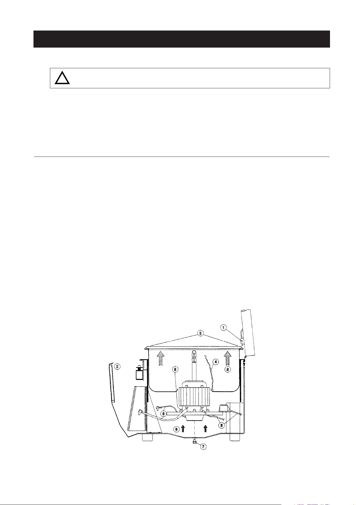
4.1. MOTOR REPLACEMENT
4.1.1. UNREFRIGERATED MODEL (C3i)
Dismounting
- Remove the pin (1) which joins the gas spring and the lid.
- Remove the front panel (2) by unscrewing the five screws and disconnect the power switch, the flat
cable, the display supply and the front panel ground cable. Lift the bowl seal and unscrew the three
press screws (3) of the chamber.
- Remove the bowl seal (4).
- Lift and remove the bowl (5).
- Disconnect the connectors (6) from the motor (J14), the tacho sensor (J4), the imbalance sensor (J7), the
microprocessor + power pcb, the motor earthing faston and the thermoswitch connection.
- Unscrew the motor press screw (7) located at the base of the motor.
- Lift and remove the motor (8).
- To separate the stabilizer from the motor, insert Allen key n°4 between the cooling ribs of the motor
perpendicularly to the screws. Repeat it for the 4 screws.
Refitting
- Carry out the above operations in the reverse order.
4 REPLACEMENT PROCEDURES
FIG. 4.1 - DISMOUNTING THE MOTOR OF THE C3i
!
Page 29
C3i-M
4 - 2
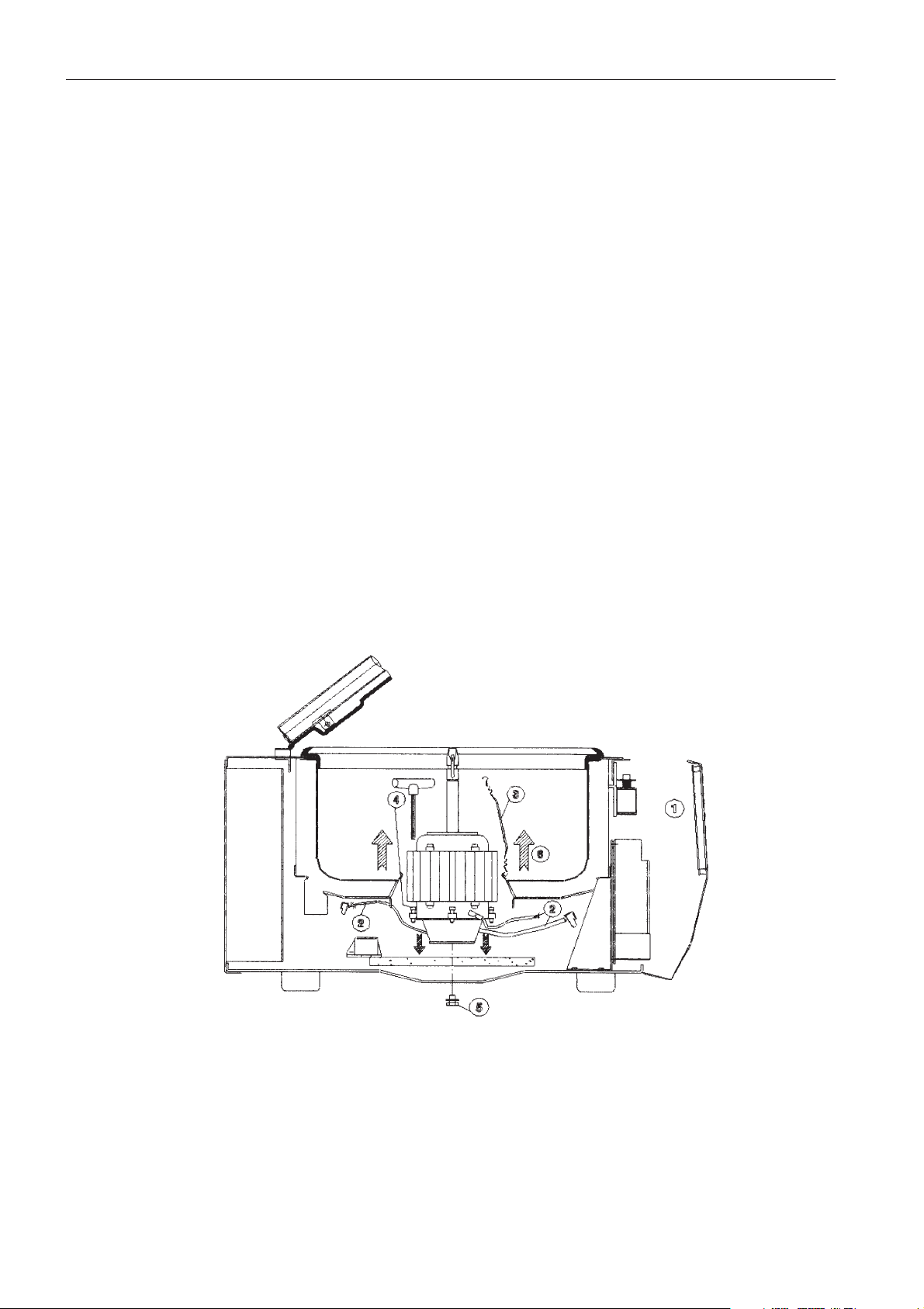
4.1.2. REFRIGERATED MODEL (CR3i)
Dismounting
- Remove the front panel (1) by unscrewing the five screws and disconnect the power switch, the flat
cable, the display supply and the front panel ground cable.
- Remove the Panduit connector from the motor (J14) and from the tacho sensor (J4) of the motor board
(see connectors), then remove the motor earthing fastons and the thermoswitch connection.
- Remove the seal in the base of the bowl
- To separate the stabilizer from the motor, insert Allen key n°4 between the cooling ribs of the motor,
perpendicularly to the screws. Repeat it for the 4 screws.
- Unscrew the motor screw located at the base of the rotor
- Lift the motor and withdraw it through the opening in the middle of the bowl
Remounting
- Carry out the above operations in the reverse order. It is easier to insert stabilizer screws before
inserting the motor into the centrifuge.
- To remount the stabilizer lying on the bottom of the machine, present the motor and turn it until the bolts
located in the lower part of the armature engage the holes in the stabilizer. Screw in the bolts which will
lift the stabilizer until it is rigidly mounted against the motor.
FIG. 4.2 - DISMOUNTING THE MOTOR OF THE CR3i
Page 30
C3i-M
4 - 3
4.2. IMBALANCE DETECTOR REPLACEMENT
Dismounting
- On the C3i, lift the bowl seal and remove the 3 press screws to remove the bowl. On the CR3i, remove
the front panel by unscrewing the 5 screws and disconnecting the power switch, the flat cable, the
display supply and the front panel ground cable.
- Remove the microprocessor + power pcb, disconnecting
all the electrical connections.
- The sensor is located on the motor stabilizer.
- Unscrew the 2 screws and remove the sensor from the
stabilizer.
Refitting
- Carry out the above operations in the reverse order.
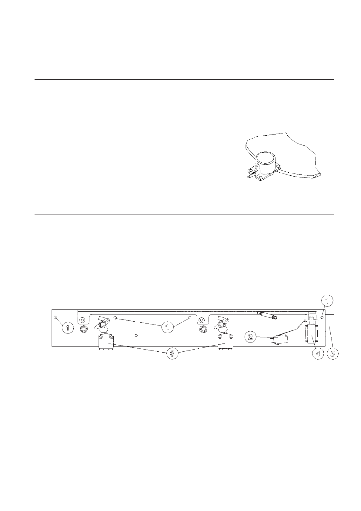
4.3. REPLACEMENT OF THE LID LOCK ASSEMBLY
Dismounting
- Open the lid
- Remove the front panel by unscrewing the 5 screws and disconnecting the power switch, the flat cable,
the display supply and the front panel ground cable.
- Disconnect the lid lock assembly of the microprocessor + power pcb by disconnecting the J8 and J10
connectors.
- Unscrew the 4 nuts on the body of the instrument.
- Remove the lid lock assembly.
Refitting
- Remount the lid lock assembly on the body, in alignment with the fixing points and keeping it in position
thanks to the nuts (1).
- Check the correct position of the lock to have a convenient lid closing.
- Screw down the nuts to the body of the instrument.
- Reconnect the electrical connectors.
- Remount the front panel.
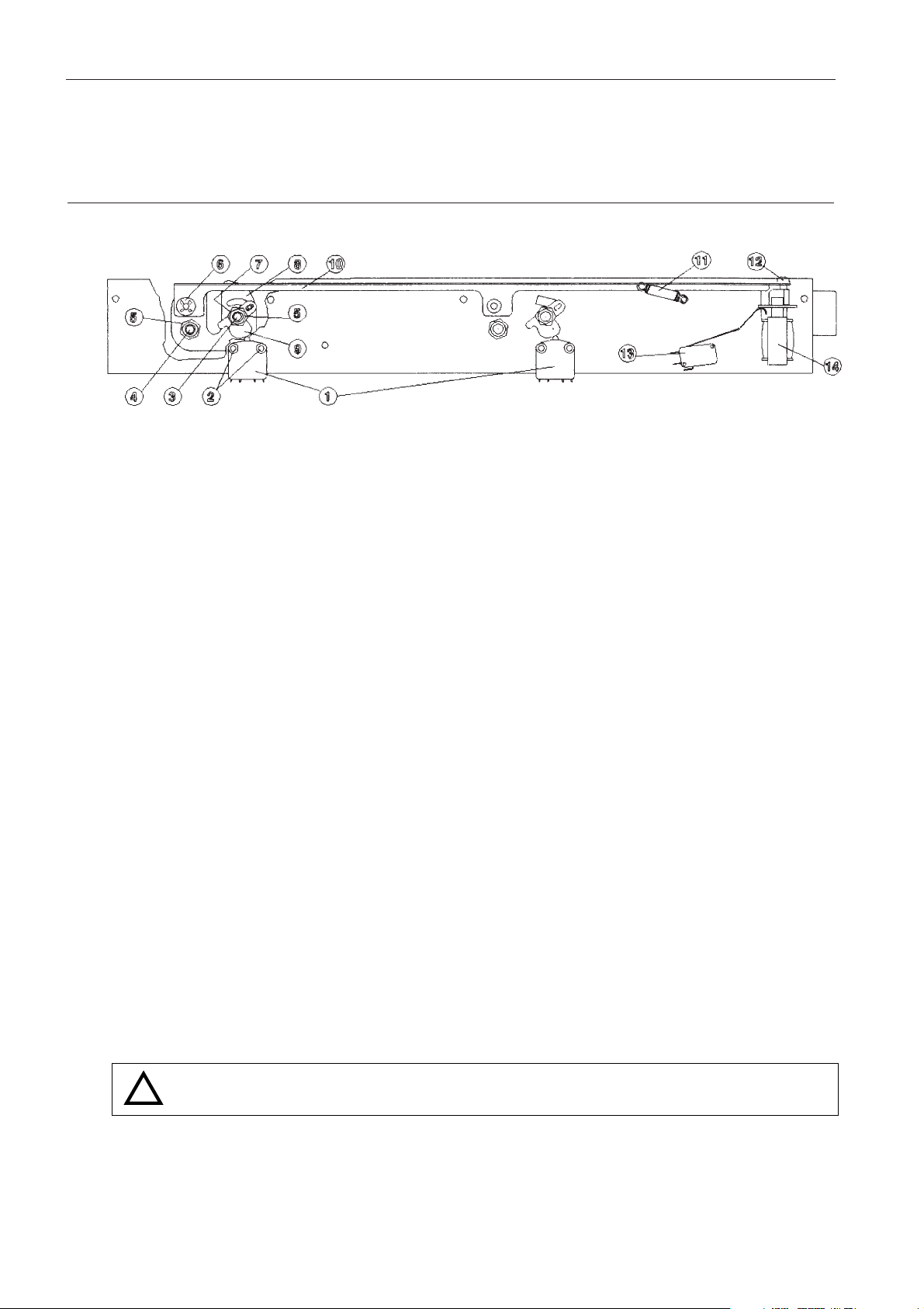
1. Nuts
2. Solenoid microswitch
3. Lid microswitch
4. Solenoid
5. Lid handle
Page 31
C3i-M
4 - 4
4.4. LID LOCK ASSEMBLY ELEMENT REPLACEMENT
4.4.1. LID LOCK MICROSWITCH REPLACEMENT
Dismounting
- Disconnect the microswitch.
- Unscrew the mounting bolts (2), dismount the microswitch.
Refitting
- Carry out the above operations in the reverse order. Check the microswitch rod does not hit the cam
when the lid is open to avoid false alarm.
4.4.2. LID LOCK REPLACEMENT
Dismounting
- Unscrew the self locking nuts (5).
- Extract the screw (4) and the cam (9).
- Extract the serrated lock washer (6).
- Unscrew the bolt (7) located behind the cam (9).
- Maintaining the lock (8), unscrew and extract the screw (3).
4.4.3. LOCK SOLENOID MICROSWITCH REPLACEMENT
Dismounting
- Disconnect the microswitch (13).
- Maintaining it, unscrew the screw located on the diagonal
Refitting
- Carry out the above operations in the reverse order.
WARNING : THE MICROSWITCH ROD HAS TO BE SHAPED TO WORK PROPERLY AND TO
GIVE A GOOD STROKE TO THE SOLENOID MOBILE CORE.
!
Page 32
C3i-M
4 - 5
4.4.4. SOLENOID REPLACEMENT
Dismounting
- Disconnect the solenoid by cutting the 2 wires at the level of the sleeves.
- Supporting the solenoid, unscrew the screws on the back of the lid lock assembly panel.
Refitting
- Carry out the above operations in the reverse order.
- Check the stroke of the solenoid mobile core is unimpeded.
- Resolder the 2 wires to the solenoid, not forgetting to fit the insulating sleeves.
NB : Solenoid microswitch and lid lock microswitch replacement can be performed without having to
remove the whole lid lock assembly.
4.5. POWER SUPPLY RACK REPLACEMENT
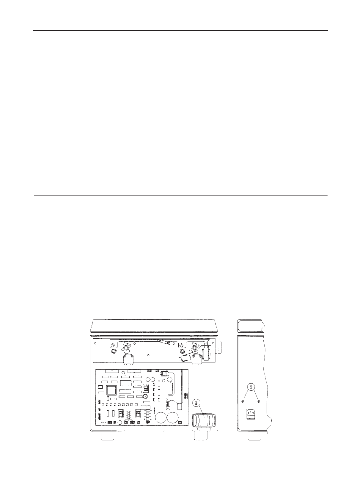
4.5.1. RACK REPLACEMENT FOR THE C3i
Dismounting
- Remove the front panel.
- Unscrew the 2 screws at the back of the machine.
- Unscrew the screw situated in front of the transformer.
- Remove all electrical connections : J1, J2, J9, J12, J13, supply and earth cables.
- Remove the rack.
Refitting
- Carry out the above operation in the reverse order.
Page 33
C3i-M
4 - 6
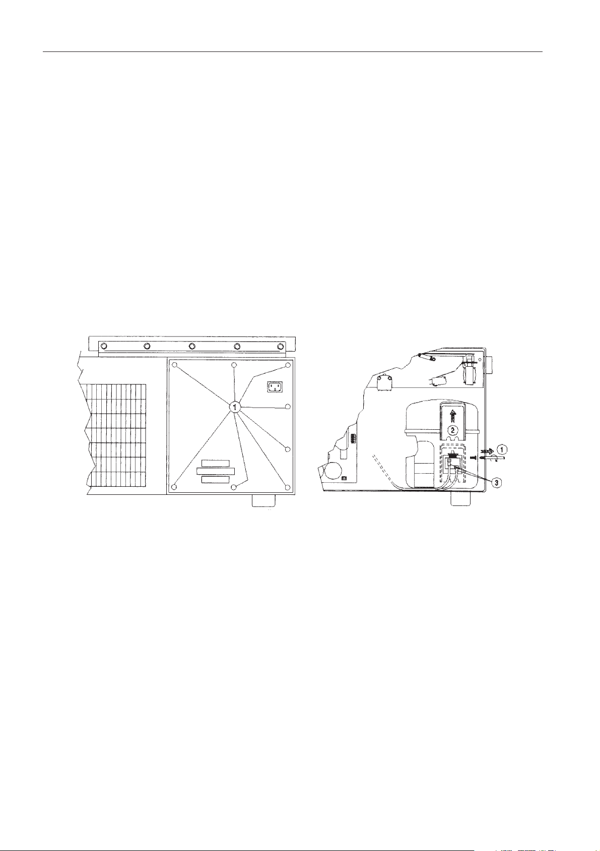
4.5.2. RACK REPLACEMENT FOR THE CR3i
Dismounting
- Remove the front panel.
- Disconnect all wirings : J1, J2, J9, J11, J12, J13, supply and earthing cables.
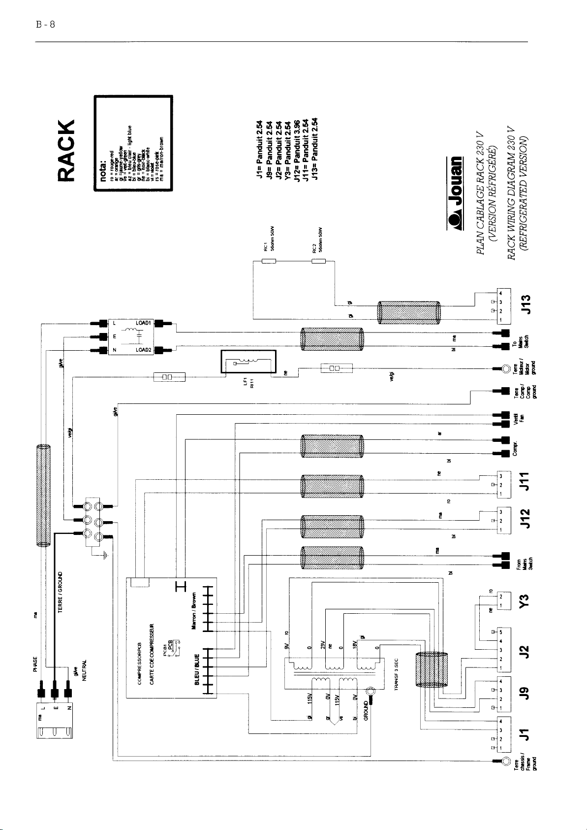
- To disconnect compressor command cables, follow the diagram below methodically.
- Remove the back panel by unscrewing the 8 protection screws.
- Free the cables from their loom.
- Extract the rack.
Refitting
- Carry out the above operations in the reverse order.
WARNING : Carefully replace the cables in their original position.
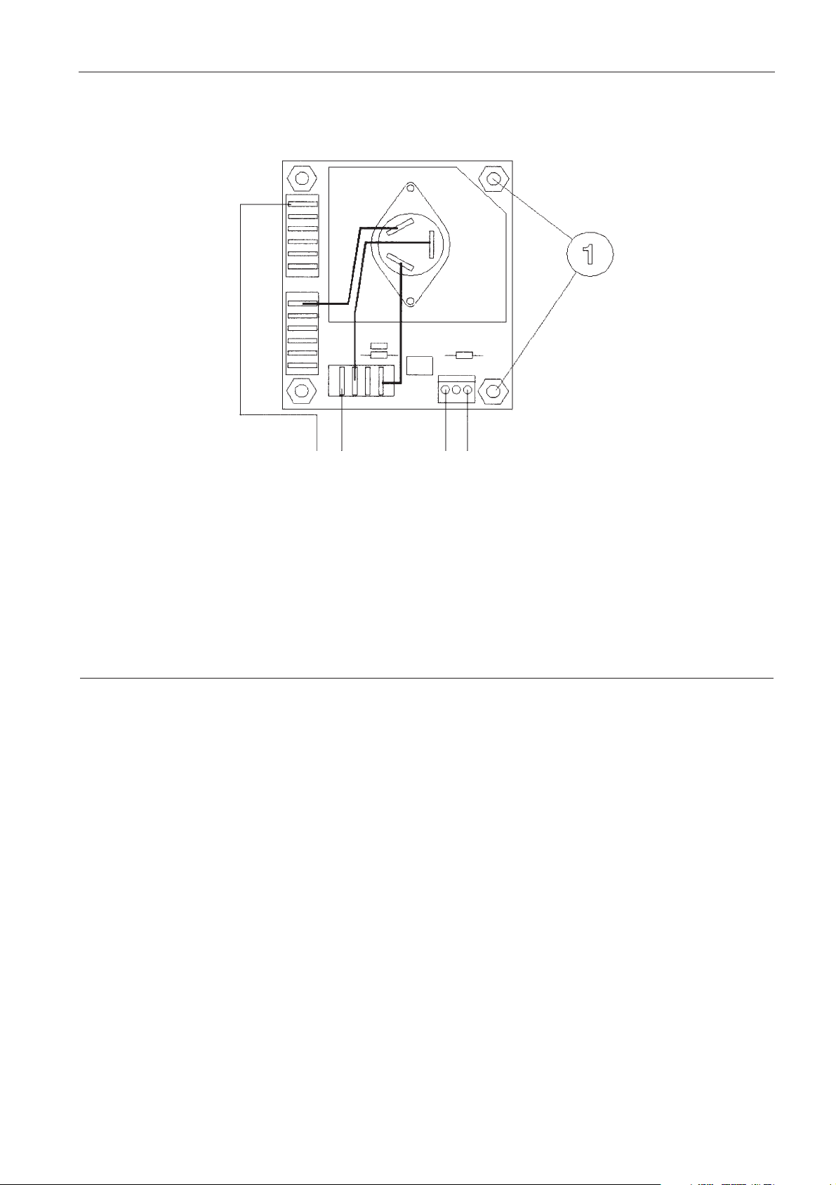
4.5.3. REFRIGERATION BOARD REPLACEMENT (CR3i)
This board is bound to the supply rack (figure 2.6, item 2). It will be necessary to remove the rack, as
described below, to have access to the board.
Dismounting
- Disconnect the board.
- Remove the board from the rack unscrewing the 4 screws (1).
Refitting
- Carry out the above operations in the reverse order.
Page 34
C3i-M
4 - 7
4.6. ELECTRONIC BOARD REPLACEMENT
4.6.1. MICROPROCESSOR + POWER PCB
Dismounting
- Remove the front panel.
- Disconnect all cables from the board : J1, J2, J3, J4, J5, J6, J7, J8, J9, J10, J11, J12, J13, J14, P1, P2.
- Unscrew the 5 screws holding the board; one in each corner and one in the middle of the board.
Remove the board.
Refitting
Carry out the above operations in the reverse order, and do not forget to place the insulation sheet
between the board and its support.
BLUEBROWN
TO THE COMPRESSOR
FROM µP P.C.B.
Page 35
C3i-M
4 - 8
4.7. KEYBOARD REPLACEMENT
- Open the front panel and disconnect the keyboard.
- Unstick and remove the keyboard.
- Clean the plastic mounting
- Fit a new keyboard. Press firmly across the whole surface to ensure adhesion.
4.8. GAS SPRING REPLACEMENT
4.8.1. GAS SPRING REPLACEMENT ON THE C3i
The gas spring appears on the figure 2.3, item 8 (chapter 2). For its replacement follow the C3i motor
replacement procedure (4.1.1).
- Follow motor replacement procedure from step 1 to 4 (included).
- Remove the 4 screws that fix the rack to the machine, then disconnect and remove the rack.
- Now only the foot of the gas spring remains screwed.
- Remove the screw and then remove the gas spring.
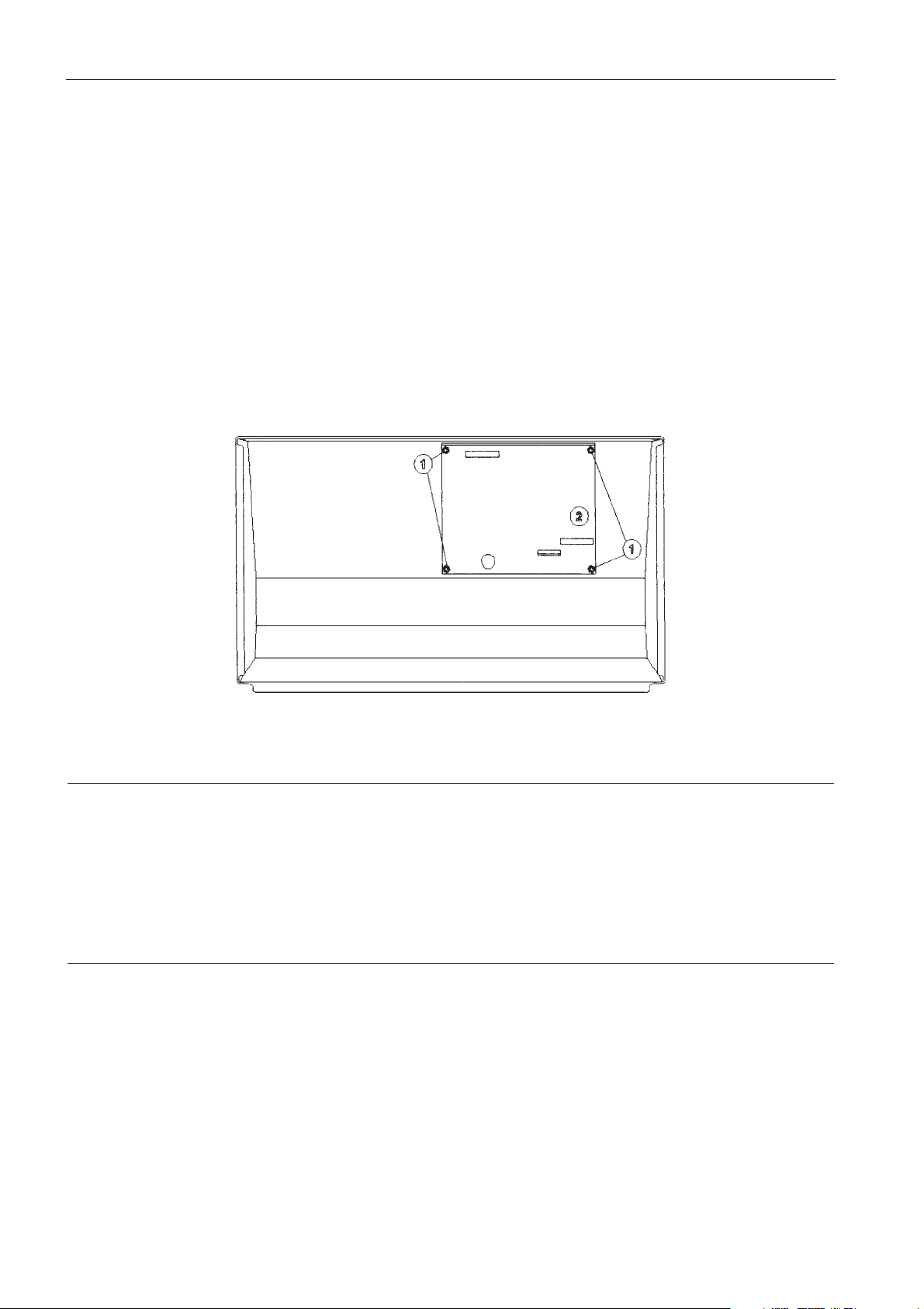
4.6.2. DISPLAY BOARD
Dismounting
- The board is located behind the front panel; the latter has to be removed by unscrewing the five press
screws and by disconnecting the power switch, the flat cable, the display supply and the front panel
ground cable.
- Unscrew the four holding nuts (1) and remove the board (2).
Refitting
- Carry out the above operations in the reverse order.
Page 36
C3i-M
4 - 9
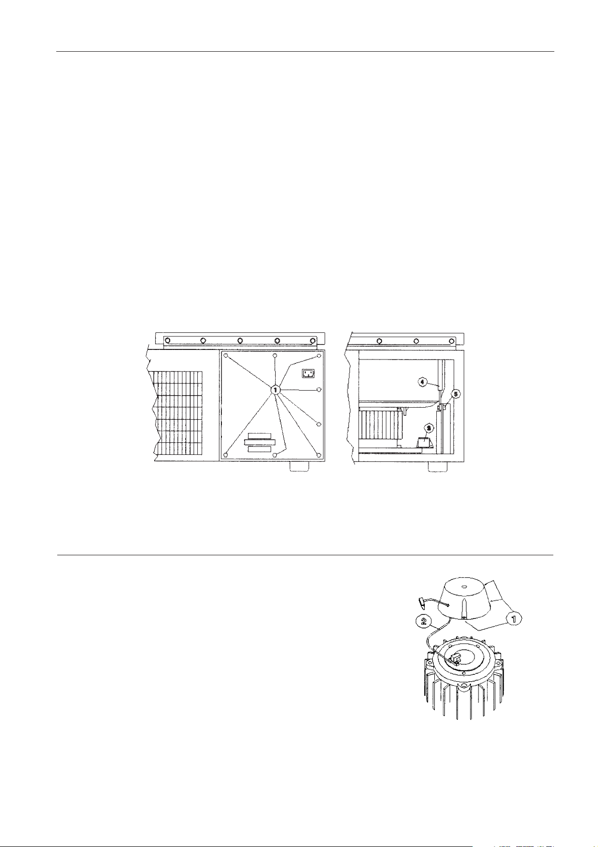
4.8.2. GAS SPRING REPLACEMENT ON THE CR3i
Dismounting
- Open the lid.
- Open the supply rack panel (1).
- Looking inside the machine from behind, the gas spring (4) can be easily seen on the right side.
- Remove the pin which joins the gas spring to the lid.
- Now only the foot of the gas spring remains connected.
- Remove the screw (5).
- Remove the gas spring.
Refitting
- Carry out the above operations in the reverse order.
4.9. TACHO REPLACEMENT
Dismounting
- Remove the shock absorber by unscrewing the 3 fastening
screws.
- Unscrew the two locking screws of the optical sensor.
Remove it while being careful of the cable.
Refitting
- Carry out the above operations in the reverse order.
Page 37
C3i-M
4 - 10
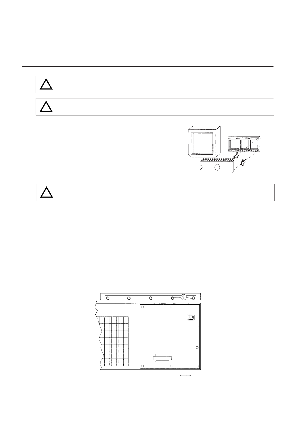
4.10. EPROM REPLACEMENT
WARNING : TO EXTRACT THE EPROM USE A PROPER EXTRACTOR AND NOT ANY TOOL
THAT COULD DAMAGE THE EPROM AND ITS SOCKET.
WARNING : DURING THE REPLACEMENT, MAINTAIN THE EPROM PARALLEL TO ITS
SOCKET.
Extraction
- Remove the front panel.
- To replace the EPROM, it is not necessary to remove
the microprocessor + power pcb from its support.
- Extract the EPROM
Insertion
- See the adjacent figure.
WARNING : INSERT THE NEW EPROM WITH THE NOTCH TOWARDS THE
MICROPROCESSOR.
- Execute the necessary calibration as explained in chapter 5.
4.11. LID REPLACEMENT
- Open the lid.
- As explained in the motor replacement procedure (4.1), extract the pin which binds the gas spring and
the lid.
- Unscrew the 5 screws which bind the lid to the hinge (1).
- Remove the lid.
!
!
!
Page 38
C3i-M
4 - 11
4.12. REFRIGERATION GROUP REPAIRS (CR3i)
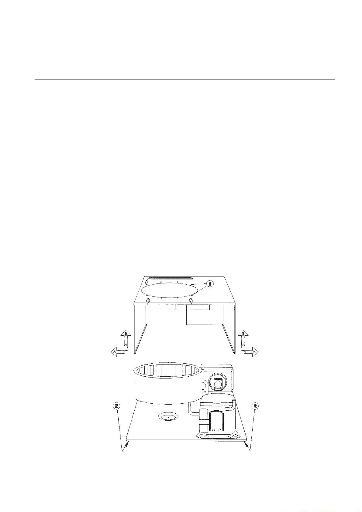
4.12.1. REFRIGERATION GROUP REPLACEMENT
Dismounting
Refering to procedures already described and to the following figure :
- Disconnect every cable.
- Remove the lid.
- Remove the motor.
- Remove the front panel.
- Remove the suplly rack.
- Remove the Microprocessor + pcb.
- Insert a block between the body and the bowl to support the bowl.
- Unscrew the eight screws (1) which bind the bowl.
- On the body : unscrew the five screws of the left side (2) and the five screws of the right side (2).
- Now, the centrifuge walls are separated from the body. To extract them, bend the wall to the outside (A)
and lift the body (B).
- The refrigeration group remains fixed only to the body.
Refitting
- Carry out the above opeartions in the reverse order.
Page 39
C3i-M
4 - 12
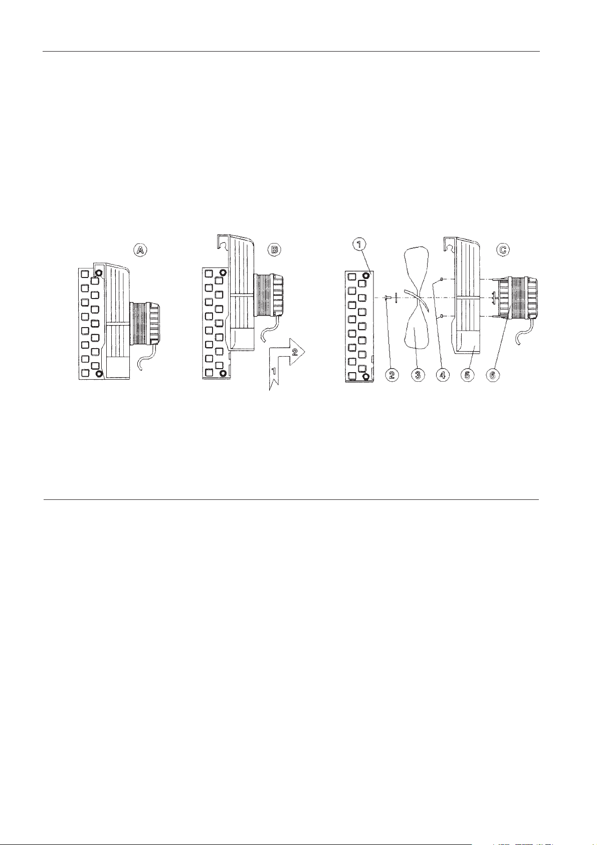
4.12.2. CONDENSER COMPONENTS REPLACEMENT
- Access the refrigeration group as escribed above.
- The condenser is in one block (A).
- Dismount it lifting and shifting the motor fan block (B).
- Separate the different parts (C).
4.13. MOTOR CHECKING
To check the motor electrical circuit integrity, continuity between phases has to be checked.
As there are three wires, such a measurement has to be carried out alternately, at the terminals of two of
them, choosing the third one as common.
The two resistance values obtained referred to two successive phases (as the state circuit is star-
configured). Check that :
1. The two values are identical (allowable difference ± 0.2 Ω).
2. The two values are not lower than 7 Ω (± 0.2 Ω).
3. There is no discontinuity.
If there is no conformity to condition 1, the motor can run erratically.
If there is no conformity to condition 2, the motor can run irregularly with over heating.
If there is no conformity to condition 3, the motor cannot run.
Page 40
C3i-M
4 - 13
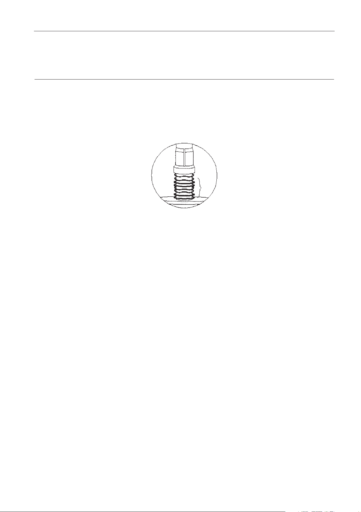
4.14. CHECKING AND MAINTENANCE OF THE CENTERING GROUP
Referring to the following figure, it is very important to check :
- The numbers and the correct positionning of washers.
- The free movement along the centering core shaft.
- The correct greasing of washer (see spare parts).
Page 41

C3i-M
5 - 1
Replacement of spare parts and adjustment are done using standard tools of a maintenance engineer
specialised in laboratory equipment.
As a guide, a list is given in the appendix. If, for a particular reason, any other tools are required, these are
clearly specified in the relevant chapter.
5.1. IMBALANCE ADJUSTMENT
Adjustment procedure
When replacing the EPROM, all previously saved information is lost. In case of no calibration, to avoid
unecessery repairs, the EPROM contains imbalance threshold default value 350.
WARNING : CALIBRATION MUST ALWAYS BE PERFORMED.
Thanks to a self learning of the vibration peak by the microprocessor, the calibration is no longer a manual
procedure.
Carry out the following steps :
- Press simultaneously the ACCEL and BRAKING keys when the machine is switched on to access the
configuration menu.
- The speed display will indicate TEST during three second, then the timer display will indicate T-1.
- Pressing START key will display IMBAL on the speed display and on the timer display :
.
If the EPROM has just been replaced the default value will be 350.
.
A value between 0 and 999 is possible if a calibration has already been done.
- Fit an S40 rotor.
- Simulate the maximum tolerable imbalance by placing an 8g weight in one of the inserts.
WARNING : THE ROTOR MUST BE PERFECTLY BALANCED BEFOREHAND.
- Close the lid and press PULSE key.
- Wait until the machine has completed the learning run. At the end of the run a value between 200 and
700 is displayed. If the result is different repeat the calibration. If you cannot succeed in having a good
result, call the manufacturer’s service department.
- Press STOP key to exit the configuration menu.
5 CHECKS, ADJUSTMENTS, CALIBRATION
!
!
Page 42

C3i-M
5 - 2
5.2. TEMPERATURE SENSOR CALIBRATION (CR3i)
Method of calibrating the temperature measurement system
Every time that the EPROM is replaced this operation must be carried out because of the loss of all
previously saved information.
WARNING : NO TEMPERATURE SENSOR CALIBRATION WOULD RESULT IN BAD
TEMPERATURE CONTROL
Thanks to a self learning of the chamber temperature, by the microprocessor, the calibration is not a
manual procedure.
Carry out the following steps :
- Remove the front panel.
- Take of the J5 connector (of the temperature sensor), slot it in the next pin above.
- Press the ACCEL and BRAKING keys simultaneously when the machine is switched on to access the
configuration menu.
- The speed display will indicate TEST during 3 seconds, then the timer display will indicate T-1.
- Press simultaneously the ▼▼ and ▲▲ temperature programming keys to run the learning cycle. Both speed
and timer display will blink during 3 seconds (time of the learning phase). then the temperature display
will indicate the value 37, meaning that the calibration coefficient has been calculated with regard to a
reference voltage corresponding to 37°C.
- Press STOP key to exit from the configuration menu.
- Put the J5 connector back in its former position.
- Close the front panel.
!
Page 43
C3i-M
6 - 1
6.1. GENERAL
6 SPARE PARTS - DIAGRAMS
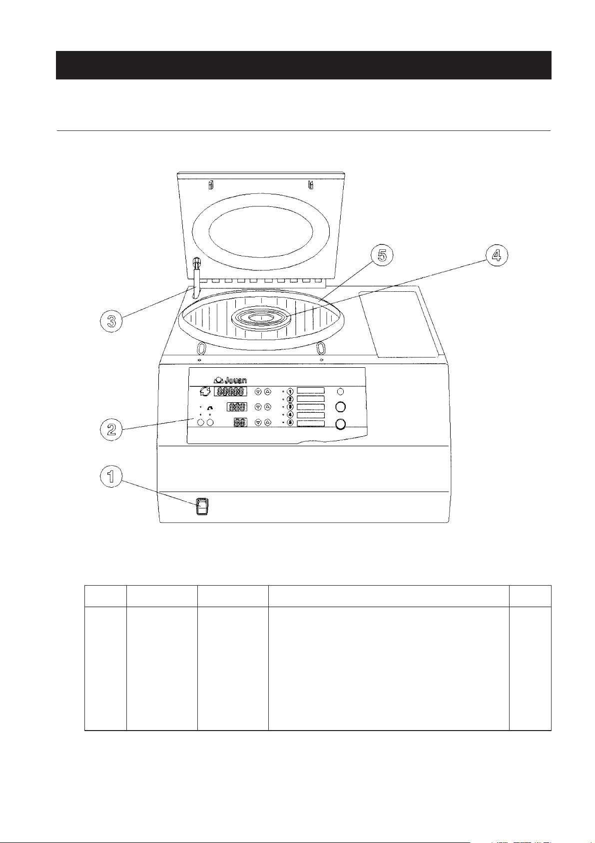
Item C3i Cat. N° CR3i Cat. N° Description Qty
1 89000838 86001434 Power switch 1
2 85220838 85220761 Keyboard 1
3 89000840 89000840 Gas spring 1
4 89000839 89000839 Motor chamber/bowl seal 1
5 89000841 89000943 Lid/bowl seal 1
- 85280460 85280460 Main p.c.b. 1
- 85280514 85280514 Display p.c.b. 1
Page 44
6 - 2
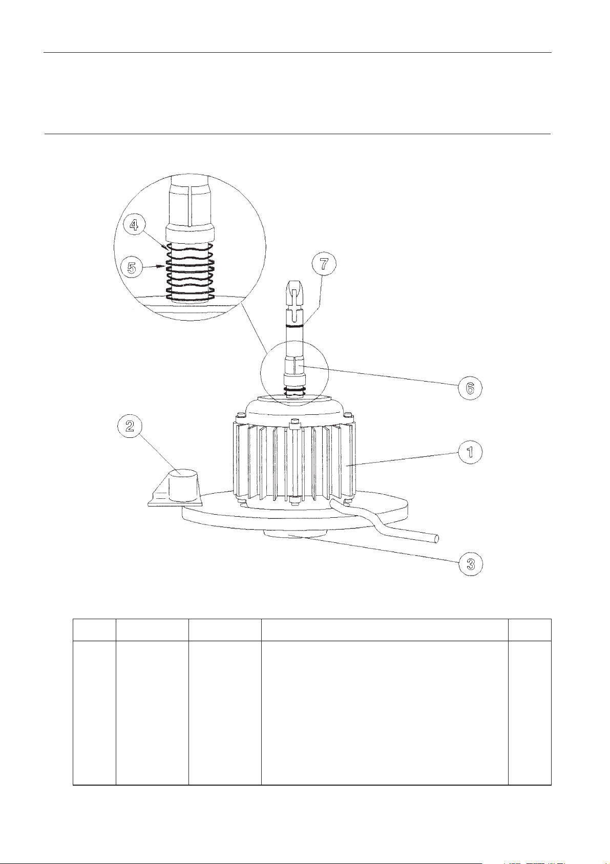
6.2.MOTOR
C3i-M
Item C3iCat. N° CR3iCat. N° Description Qty
1 89000836 89000836 Motor 1
2 89000843 89000843 Load imbalance sensor 1
3 89000853 89000853 Elastic suspension 1
4 89000851 89000851 Spring washers 4
5 89000850 89000850 Washers 4
6 89000849 89000849 Motor shaft clamp 1
7 89000852 89000852 O-Ring 1
- 89000853 89000853 Tachometer sensor assy 1
Page 45
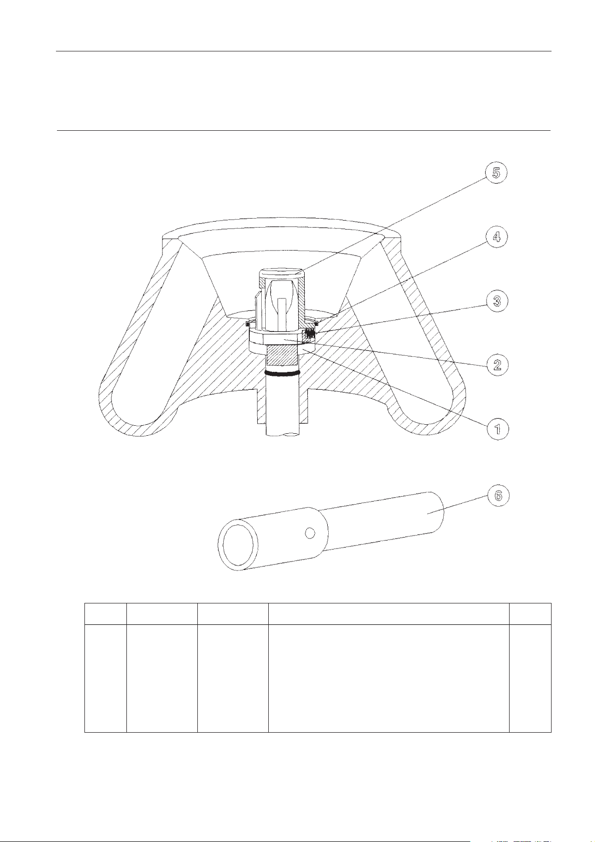
6.3.AUTO-LOCK SYSTEM
6 - 3
Item C3iCat. N° CR3iCat. N° Description Qty
1 89002451 89002451 Guide collar 1
2 85230757 85230757 Latch 1
3 86001482 86001482 Spring 1
4 86001600 86001600 Circlip 1
5 89000917 89000917 Latch guide 1
6 89002391 89002391 Rotating equipment unlocking device 1
C3i-M
Page 46
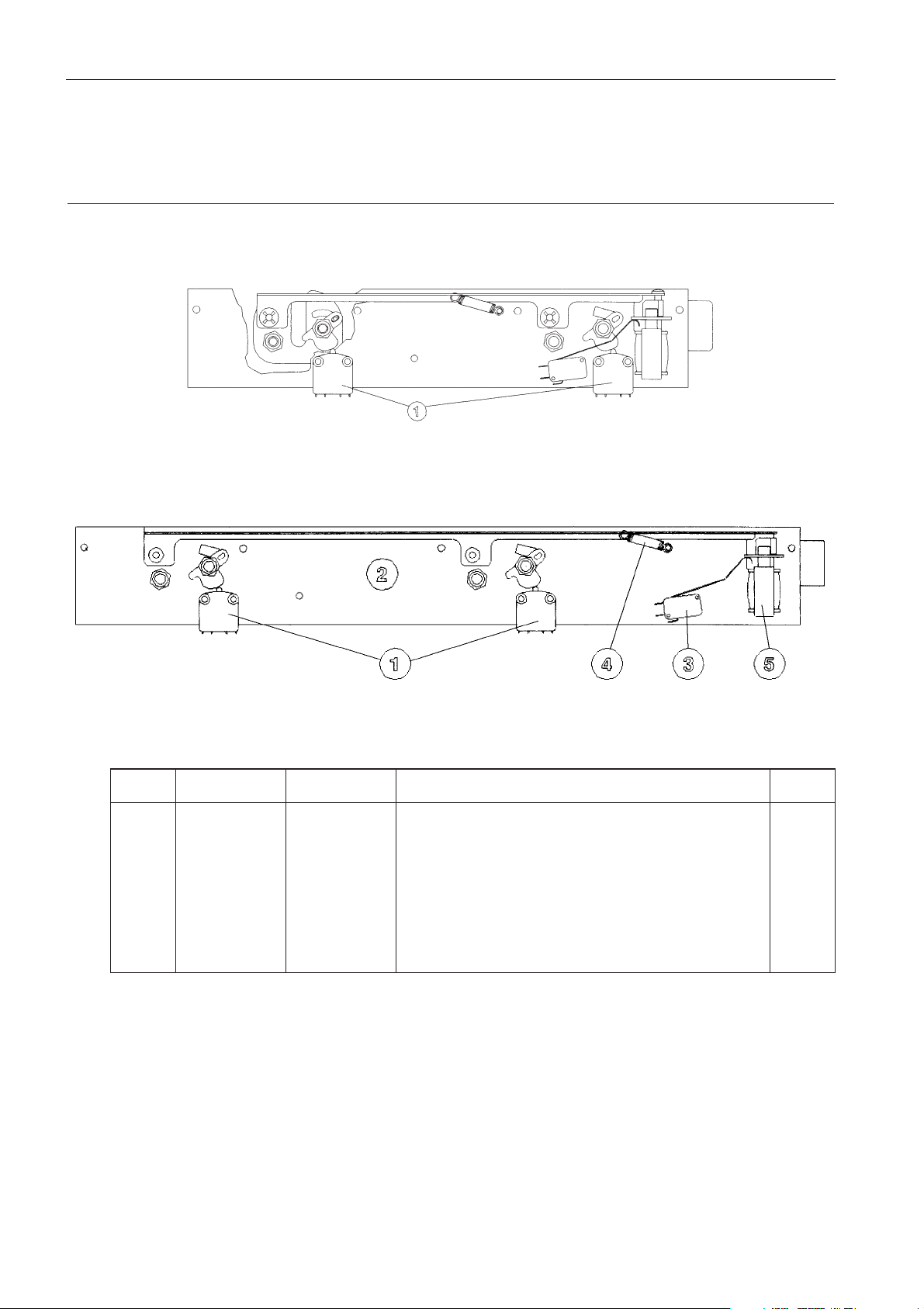
6 - 4
6.4.LOCK
C3ilid lock
CR3ilid lock
Item C3iCat. N° CR3iCat. N° Description Qty
1 89000842 89000842 Lid microswitch 2
2 89000844 89000844 Lock 1
3 89000845 89000845 Solenoid switch 1
4 89000846 89000846 Locking system spring 1
5 89000847 89000847 Lid solenoid 1
6 11202913 11202914 Locking system assembly 1
C3i-M
Page 47
C3i-M
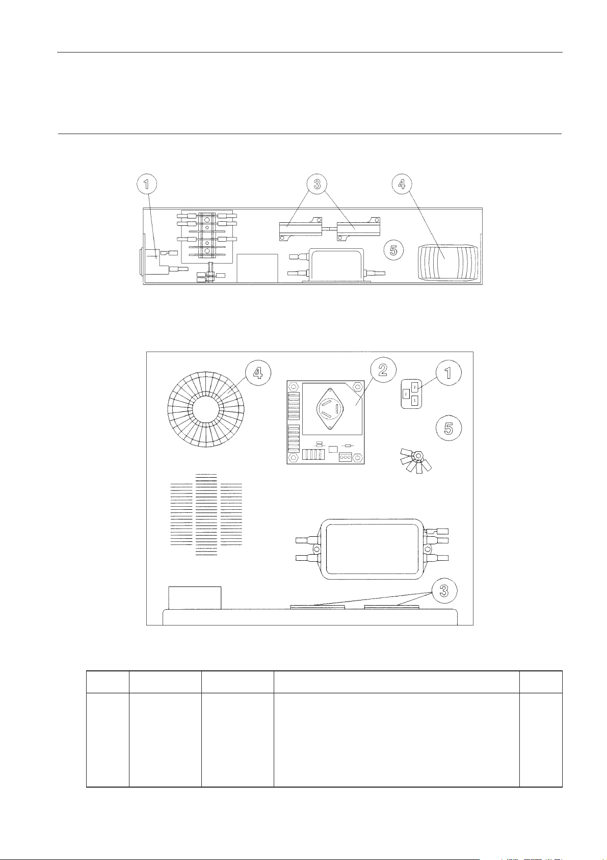
6 - 5
Item C3i Cat. N° CR3i Cat. N° Description Qty
1 89000900 89000900 Mains connector 1
2 - 85280383 Compressor p.c.b. 1
3 89000854 89000854 Braking resistor 2
4 89000837 89000837 Transformer 1
5 89000855 89000882 Feeder group 1
6.5. FEEDER GROUP
C3i feeder group
CR3i feeder group
Page 48

C3i-M
6 - 6
6.6. REFRIGERATION GROUP (CR3i)
Item C3i Cat. N° CR3i Cat. N° Description Qty
1 - 89000902 Bowl assembly 1
2 - 89000903 Condenser group assembly 230V - 50Hz 1
2 - 89000904 Condenser group assembly 120V - 60Hz 1
3 - 89000905 Compressor 230V - 50Hz 1
3 - 89000906 Compressor 120V - 60Hz 1
Page 49
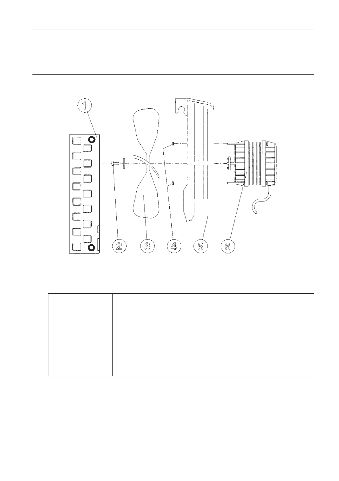
C3i-M
6 - 7
6.7. CONDENSER GROUP (CR3i)
Item C3i Cat. N° CR3i Cat. N° Description Qty
1 - 89000907 Condenser 1
2 - 89000908 Screw 1
3 - 89000909 Fan blades 1
4 - 89000910 Motor nuts 1
5 - 89000911 Carter fan blades and motor 1
6 - 89000912 Motor 230V - 50 Hz 1
6 - 89000913 Motor 120V - 60Hz 1
Page 50

C3i-M
A - 1
LISTE DE L'OUTILLAGE D'INTERVENTION STANDARD
1 Valise outillage métrique (type maintenance)
1 Chalumeau pour brasure cuivre
1 Manifold LP (0-8 bars) HP (0-30 bars)
1 Ampèremètre efficace vrai (True RMS) 0 à 6 ampères et 0 à 20 ampères
1 Multimètre/fréquencemètre :
- voltmètre AC/DC 0 - 500 V
- ampèremètre 0 - 10 A
- ohmmètre 0 - 1 MΩ
- fréquencemètre 0 - 2 KHz
1 Thermomètre à thermo-couple ou équivalent avec une précision de ±1°C dans la gamme 0 - 40°C
A ANNEXE
RECOMMENDED LIST OF TOOLS FOR STANDARD MAINTENANCE
1 Tool case (metric)
1 Welding station for copper brazing
1 Manifold LP (0-8 bars) HP (0-30 bars)
1 True RMS Ammeter 0 to 6 A and 0 to 20 A
1 Multimeter/frequency-meter :
- AC/DC voltmeter 0 - 500 V
- ampmeter 0 - 10 A
- ohmmeter 0 - 1 MΩ
- frequency-meter 0 - 2 KHz
1 Thermo-electric couple thermometer or similar with an accuracy of ±1°C in the range 0 - 40°C
A APPENDIX
Page 51

C3i-M
B - 1
SCHÉMAS ELECTRIQUES
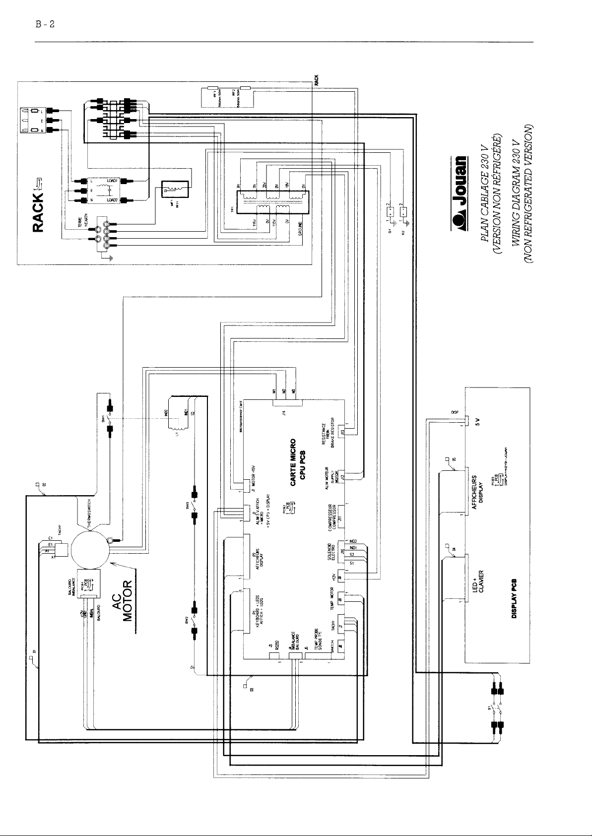
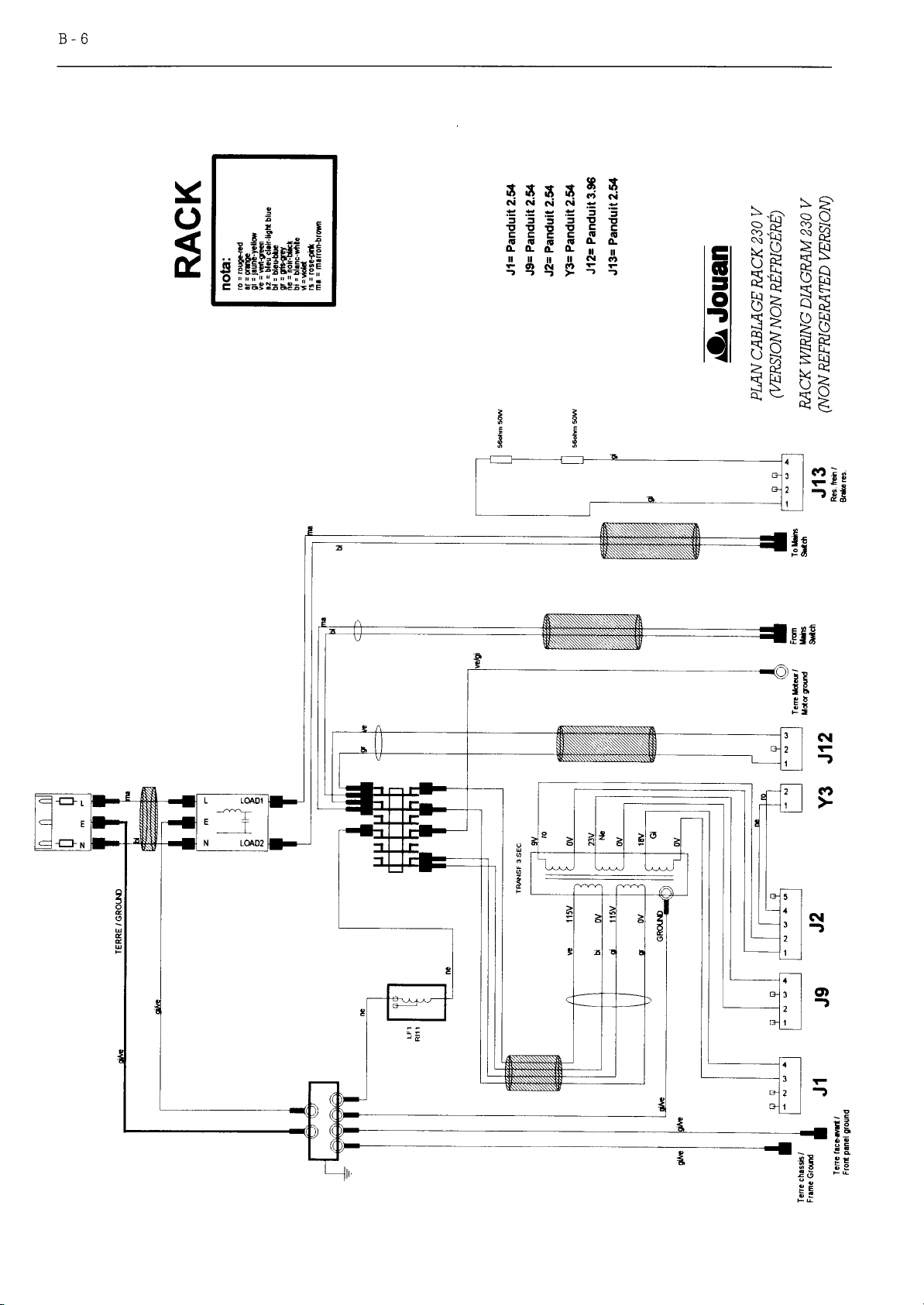
Plan cablage 230 V (version non réfrigéré) . . . . . . . . . . . . . . . . . . . . . . . . . . . . . . . . . . . . . . . . . . . . . . . . . . B-2
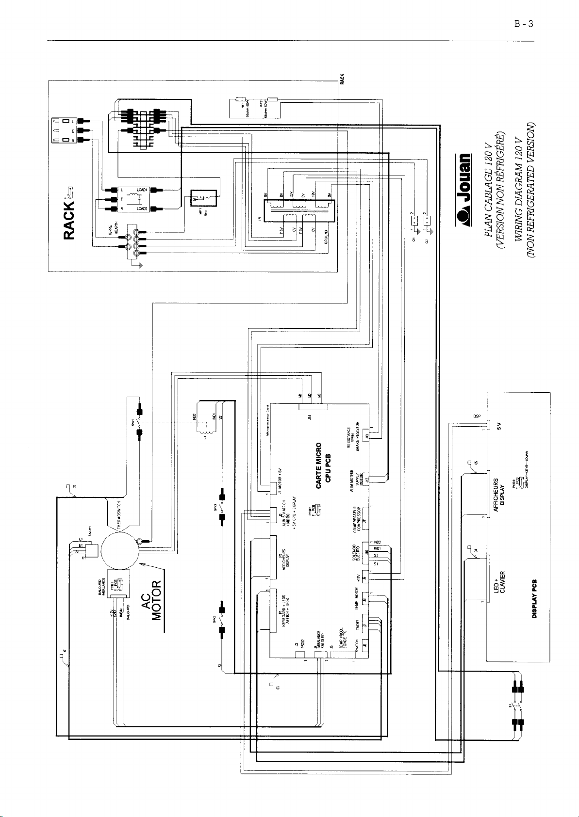
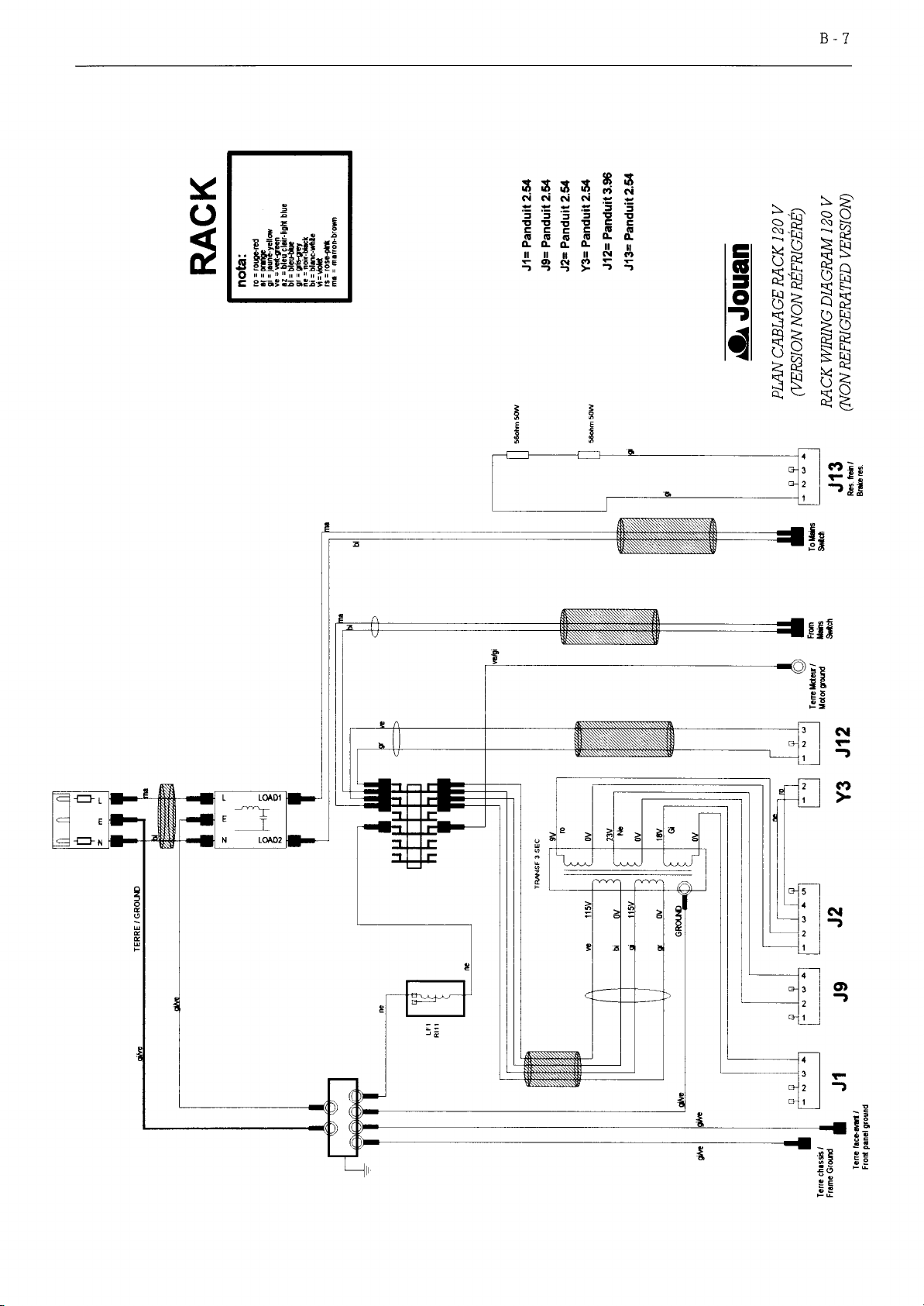
Plan cablage 120 V (version non réfrigéré) . . . . . . . . . . . . . . . . . . . . . . . . . . . . . . . . . . . . . . . . . . . . . . . . . . B-3
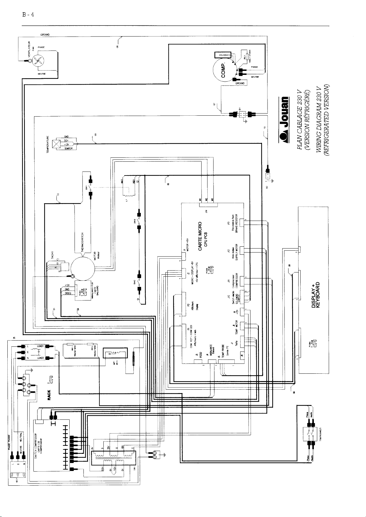
Plan cablage 230 V (version réfrigéré) . . . . . . . . . . . . . . . . . . . . . . . . . . . . . . . . . . . . . . . . . . . . . . . . . . . . . . B-4
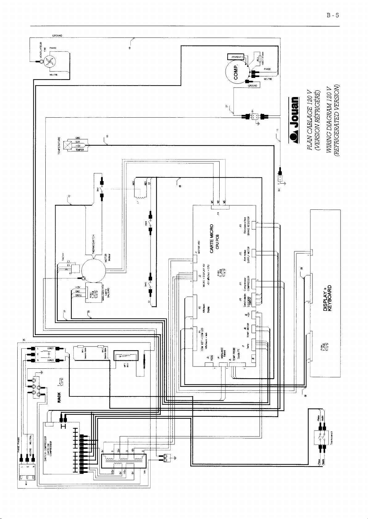
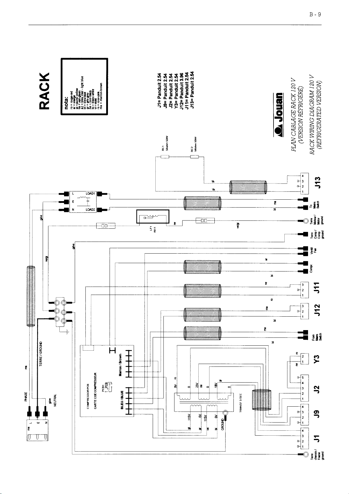
Plan cablage 120 V (version réfrigéré) . . . . . . . . . . . . . . . . . . . . . . . . . . . . . . . . . . . . . . . . . . . . . . . . . . . . . . B-5
Plan cablage rack 230 V (version non réfrigéré) . . . . . . . . . . . . . . . . . . . . . . . . . . . . . . . . . . . . . . . . . . . . . . B-2
Plan cablage rack 120 V (version non réfrigéré) . . . . . . . . . . . . . . . . . . . . . . . . . . . . . . . . . . . . . . . . . . . . . . B-3
Plan cablage rack 230 V (version réfrigéré) . . . . . . . . . . . . . . . . . . . . . . . . . . . . . . . . . . . . . . . . . . . . . . . . . B-4
Plan cablage rack 120 V (version réfrigéré) . . . . . . . . . . . . . . . . . . . . . . . . . . . . . . . . . . . . . . . . . . . . . . . . . B-5
B ANNEXE
ELECTRICAL DIAGRAMS
Wiring diagram 230 V (non refrigerated version) . . . . . . . . . . . . . . . . . . . . . . . . . . . . . . . . . . . . . . . . . . . . . B-2
Wiring diagram 120 V (non refrigerated version) . . . . . . . . . . . . . . . . . . . . . . . . . . . . . . . . . . . . . . . . . . . . . B-3
Wiring diagram 230 V (refrigerated version) . . . . . . . . . . . . . . . . . . . . . . . . . . . . . . . . . . . . . . . . . . . . . . . . . B-4
Wiring diagram 120 V (refrigerated version) . . . . . . . . . . . . . . . . . . . . . . . . . . . . . . . . . . . . . . . . . . . . . . . . . B-5
Rack wiring diagram 230 V (non refrigerated version) . . . . . . . . . . . . . . . . . . . . . . . . . . . . . . . . . . . . . . . . B-2
Rack wiring diagram 120 V (non refrigerated version) . . . . . . . . . . . . . . . . . . . . . . . . . . . . . . . . . . . . . . . . B-3
Rack wiring diagram 230 V (refrigerated version) . . . . . . . . . . . . . . . . . . . . . . . . . . . . . . . . . . . . . . . . . . . . B-4
Rack wiring diagram 120 V (refrigerated version) . . . . . . . . . . . . . . . . . . . . . . . . . . . . . . . . . . . . . . . . . . . . B-5
B APPENDIX
Page 52
Page 53
Page 54
Page 55
Page 56
Page 57
Page 58
Page 59
 Loading...