

Page 1

EN (2-18)
IT (19-35)
GR (36-53)
SI (54-70)
PA 1100
Operator ′ s manual
Istruzioni per l’uso
√‰ËÁ›Â˜ ¯Ú‹Ûˆ˜
Navodila za uporabo
Please read the operator’s manual carefully and make sure you understand the instructions before using the machine.
Prima di usare la macchina, leggere per intero le istruzioni per l’uso e accertarsi di averne compreso il contenuto.
¢И·Я¿ЫЩВ ЪФЫВОЩИО¿ ЩИ˜ √‰ЛБ›В˜ ¯Ъ‹ЫВˆ˜ О·И О·Щ·УФ‹ЫЩВ ЩФ ВЪИВ¯fiМВУФ ЪИУ ¯ЪЛЫИМФФИ‹ЫВЩВ ЩФ МЛ¯¿УЛМ·.
Natanãno preberite navodila za uporabo in se prepriãajte, da ste jih razumeli, predno zaãnete z uporabo stroja.
Page 2
KEY T O SYMBOLS
2
– English
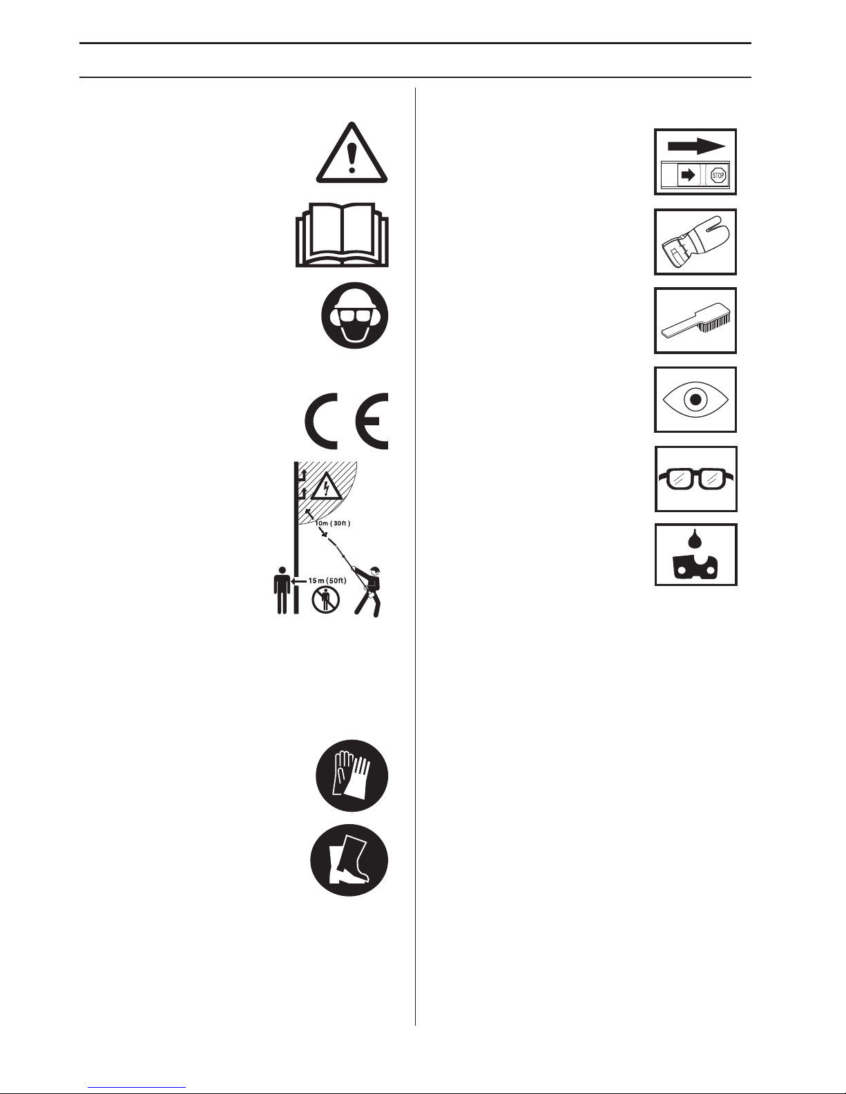
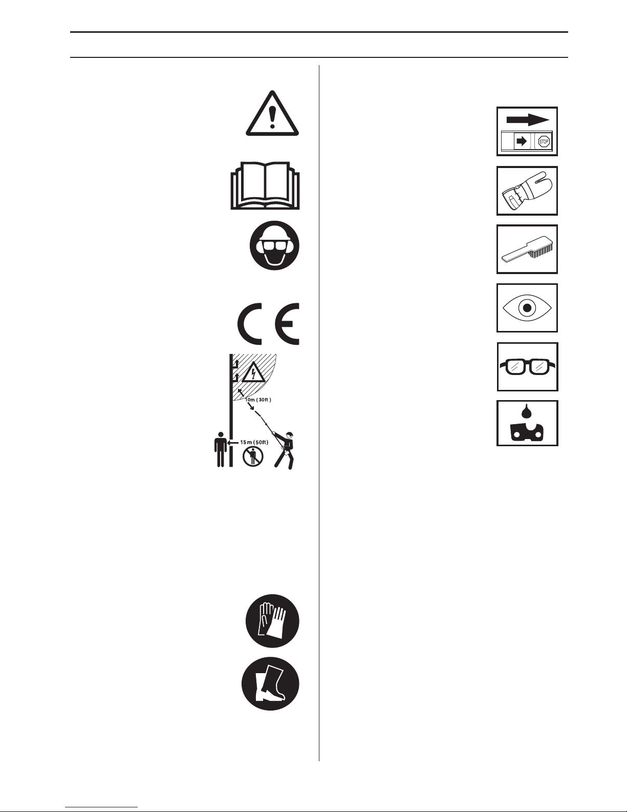
Symbols
WARNING! The machine can be a
dangerous tool if used incorrectly or
carelessly, which can cause serious or
fatal injury to the operator or others.
Please read the operator’s manual
carefully and make sure you
understand the instructions before
using the machine.
Always wear:
• A protective helmet where there is a
risk of falling objects
• Approved hearing protection
• Protective goggles or a visor
This product is in accordance with
applicable EC directives.
This machine is not electrically
insulated. If the machine
touches or comes close to highvoltage power lines it could lead
to death or serious bodily injury.
Electricity can jump from one
point to another by arcing. The
higher the voltage, the greater
the distance electricity can
jump. Electricity can also travel
through branches and other
objects, especially if they are wet. Always keep a distance
of at least 10 m between the machine and high-voltage
power lines and/or any objects that are touching them. If
have to work within this safe distance you should always
contact the relevant power company to make sure the
power is switched off before you start work.
Always wear approved protective
gloves.
Wear sturdy, non-slip boots.
Other symbols/decals on the mac hine refer to special
certification requirements for certain markets.
Switch off the engine by moving the
stop switch to the STOP position
before carrying out any checks or
maintenance.
Always wear approved protective
gloves.
Regular cleaning is required.
Visual check.
Protective goggles or a visor must be
worn.
Filling with chain oil and adjusting oil
flow
Page 3
CONTENTS
English
–
3
Contents
Note the f ollowing before
starting:
Husqv arna AB has a policy of continuous product
development and therefore reserves the right to modify
the design and appearance of products without prior
notice.
Long-term exposure to noise can result in permanent
hearing impairment. So always use approved hearing
protection.
Please read the operator’s manual carefully and make
sure you understand the instructions before using the
machine.
These instructions supplement the instructions that were
included with the machine. For other procedures, please
refer to the operating instructions for the machine.
The machine is only designed for cutting branches and
twigs.
KEY TO SYMBOLS
Symbols ................................................................ 2
CONTENTS
Contents ............................................................... 3
Note the following before starting: ........................ 3
INTR ODUCTION
Dear Customer , .................................................... 4
WHA T IS WHAT?
What is what on the sa w attachment? .................. 5
SAFETY INSTR UCTIONS
Cutting equipment ................................................ 6
Specification of bar and saw chain ....................... 6
Sharpening your chain and adjusting raker
clearance ..............................................................
7
Tensioning the chain ............................................. 9
Lubricating cutting equipment .............................. 10
Checking wear on cutting equipment ................... 11
Safety instructions for using a pruning saw .......... 12
ASSEMBL Y
Fitting the cutting head ......................................... 15
Fitting the bar and chain ....................................... 15
Fitting the suspension ring ................................... 15
Adjusting the harness ........................................... 15
Filling with oil ........................................................ 16
Check before starting ........................................... 16
TECHNICAL D ATA
T
echnical data ...................................................... 17
Guide bar and saw chain combinations ............... 17
EC Declaration of Conformity ............................... 18
!
W
ARNING! Under no circumstances may
the design of the machine be modified
without the permission of the
manufacturer. Always use original
accessories. Non-authorized
modifications and/or accessories can
result in serious personal injury or the
death of the operator or others.
!
W
ARNING! This accessory may only be
used together with the intended brush
cutter/trimmer, see under heading
”Approved accessories” in chapter
Technical data in the machine’s
Operator’s Manual.
Page 4

4
– English
INTR ODUCTION
Dear Customer ,
Cong ratulations on your choice to buy a Jonsered product!
We are convinced that you will appreciate with great satisfaction the quality and performance of our product for a very
long time to come. The purchase of one of our products gives you access to professional help with repairs and service
whenever this may be necessary. If the retailer who sells your machine is not one of our authorised dealers, ask for the
address of your nearest service workshop.
It is our wish that you will be satisfied with your product and that it will be your companion for a long time. Think of this
operator
′ s manual as a valuable document. By following its content (usage, service, maintenance, etc), the life span and
the second-hand value of the machine can be extended. If you sell this machine, make sure that the operator
′ s manual
is passed on to the buyer.
Good luck on using your Jonsered machine!
Jonsered has a policy of continuous product development and therefore reserves the right to modify the design and
appearance of products without prior notice.
Page 5

English – 5
WHA T IS WHA T?
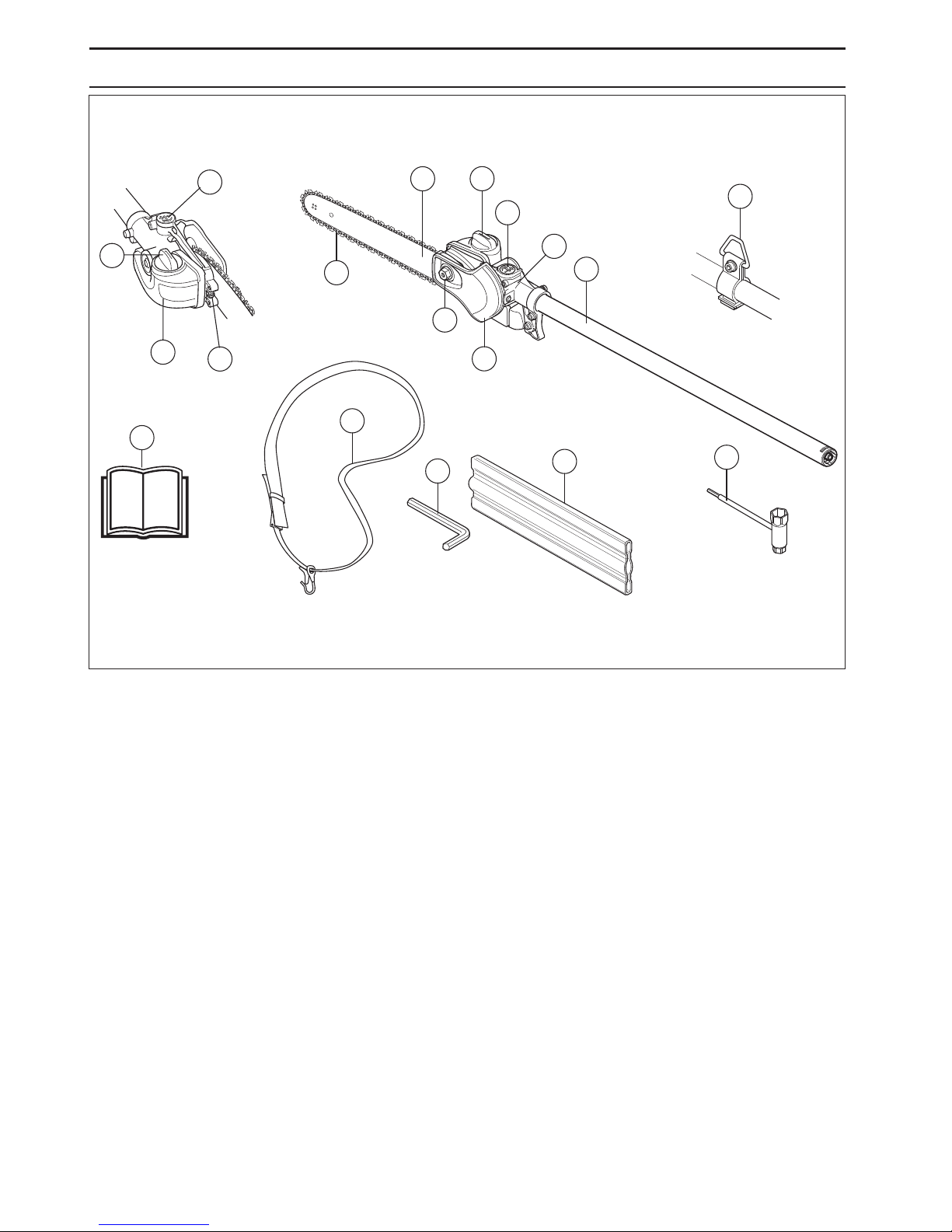
What is what on the sa w attachment? (Saw attachment with shaft PA 1100)
4
13
12
14
15
10
11
2
7
11
9
1
2
8
6
5
3
16
1
Bevel gear
2 Chain lubrication adjustment screw
3 Shaft (1100 mm)
4 Harness support hook
5 Protective guard for saw chain
6 Bar nut
7 Chain tensioning screw
8 Saw chain
9 Guide bar
10 Chain oil tank
11 Filling with chain oil
12 Operator ′ s manual
13 Transport guard
14 Combination spanner
15 Harness
16 Torx wrench
Page 6
SAFETY INSTR UCTIONS
6
– English
Cutting equipment
This section descr ibes how you can achieve maximum
clearing capacity and extend the life of the cutting
attachment through correct maintenance and using the
right type of cutting attachment.
Onl y use cutting equipment recommended by us!
See the Technical data section.
K
eep the chain’s cutting teeth properly sharpened!
Follow our instructions and use the recommended
file gauge.
A damaged or badly sharpened chain
increases the risk of accidents.
Maintain the correct raker c learance! Follow our
instructions and use the recommended raker gauge.
Too large a clearance increases the risk of kickback.
K
eep the chain properly tensioned! If the chain is slack
it is more likely to jump off and lead to increased wear on
the bar, chain and drive sprocket.
K
eep cutting equipment well lubricated and properly
maintained!
A poorly lubricated chain is more likely to
break and lead to increased wear on the bar, chain and
drive sprocket.
Specifi cation of bar and saw
chain
When the cutting attachment supplied with y our machine
has to be replaced, because it is worn out or damaged,
you must only fit the types of bar and saw chain
recommended by us.
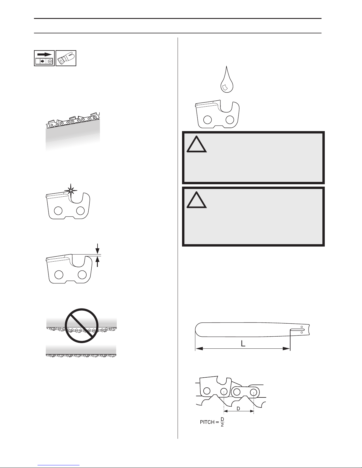
Guide bar
•
Length (inches/cm)
• Chain pitch (inches). The spacing between the drive
links of the chain must match the spacing of the teeth
on the bar tip sprocket and drive sprocket.
!
W
ARNING! Never use a machine with
faulty safety equipment. The machine's
safety equipment must be checked and
maintained as described in this section.
If your machine fails any of these checks
contact your service agent to get it
repaired.
!
W
ARNING! Always stop the engine
before doing any work on the cutting
attachment. This continues to rotate even
after the throttle has been released.
Ensure that the cutting attachment has
stopped completely and disconnect the
spark plug cap before you start to work
on it.
Page 7
SAFETY INSTR UCTIONS
English
–
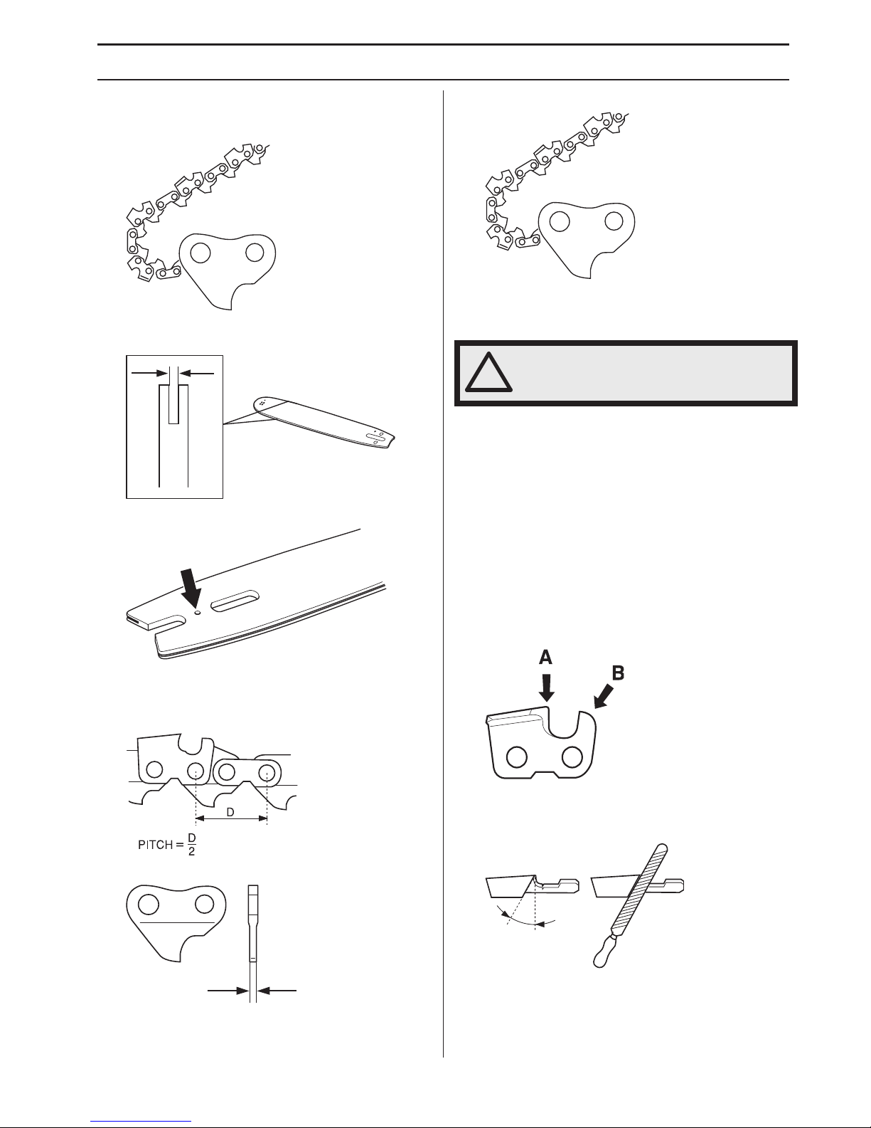
7 •
Number of drive links. The number of drive links is
determined by the length of the bar, the chain pitch
and the number of teeth on the bar tip sprocket.
• Bar groove width (inches/mm). The groove in the bar
must match the width of the chain drive links.
• Saw chain oil hole and hole for chain tensioner pin.
Sa
w chain
•
Saw chain pitch (inches). (The distance between
three drive links, divided by two.)
• Drive link width (mm/inches)
• Number of drive links.
Sharpening y our chain and
adjusting raker clearance
General inf ormation on sharpening
cutting teeth
•
Never use a blunt chain. When the chain is blunt you
have to exert more pressure to force the bar through
the wood and the cuttings will be very small. If the
chain is very blunt it will not produce any cuttings at all.
Wood powder would be the only result.
• A sharp chain eats its way through the wood and
produces long, thick cuttings. The cutting part of the
chain is called the cutting link and this consists of a
cutting tooth (A) and the raker lip (B). The cutting
depth is determined by the difference in height
between the two.
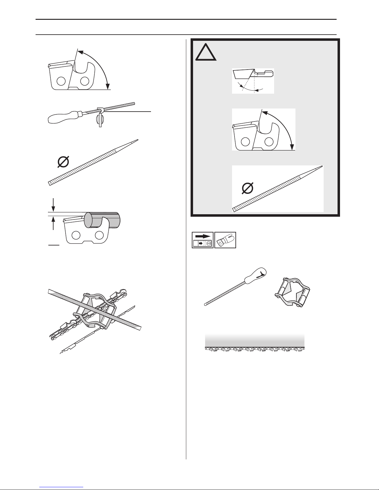
• When you sharpen a cutting tooth there are five
important factors to remember.
1 Filing angle
!
W
ARNING! The risk of kickback is
increased with a badly sharpened chain!
Page 8
SAFETY INSTR UCTIONS
8
– English
2
Cutting angle
3 File position
4 Round file diameter
5 File depth
It is very difficult to sharpen a chain correctly without the
right equipment. We recommend that you use our file
gauge. This will help you obtain the maximum kickback
reduction and cutting performance from your chain.
Sharpening cutting teeth
•
To sharpen cutting teeth you will need a round file and
a file gauge.
• Check that the chain is correctly tensioned. A slack
chain will move sideways, making it more difficult to
sharpen correctly.
1
5
!
W
ARNING! The following faults will
increase the risk of kickback
considerably: File angle too large
Cutting angle too small
File diameter too small
Page 9
SAFETY INSTR UCTIONS
English – 9
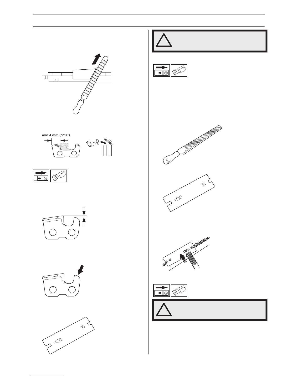
• Always file cutting teeth from the inside face outwards.
Reduce the pressure on the return stroke. File all the
teeth on one side of the bar first. Then turn the saw
over and file the remaining teeth from the other side.
• File all the teeth to the same length. When the length
of the cutting teeth is reduced to 4 mm (5/32") the
chain is worn out and should be replaced.
General advice on setting raker clearance
• When you sharpen the cutting teeth you reduce the
raker clearance (=cutting depth). To maintain optimal
cutting performance you must file back the raker lip to
the recommended height.
• On a low-kickback cutting link the front edge of the
raker lip is rounded. It is very important that you
maintain this radius or bevel when you adjust the raker
clearance.
• We recommend that you use our raker gauge to
achieve the correct clearance and bevel on the raker
lip.
Setting the raker clearance
• Before setting the raker clearance the cutting teeth
should be newly sharpened. We recommend that you
adjust the raker clearance every third time you
sharpen the chain. NOTE! This recommendation
assumes that the length of the cutting teeth is not
reduced excessively.
• To adjust the raker clearance you will need a flat file
and a raker gauge.
• Place the gauge over the raker lip.
• Place the file over the part of the lip that protrudes
through the gauge and file off the excess. The
clearance is correct when you no longer feel any
resistance as you draw the file over the gauge.
Tensioning the chain
• The more you use a chain the longer it becomes. It is
therefore important to adjust the chain regularly to
take up the slack.
• Check the chain tension every time you refuel. NOTE!
A new chain has a running-in period during which you
should check the tension more frequently.
!
WARNING! The risk of kickback is
increased if the raker clearance is too
large!
!
WARNING! A slack chain may jump off
and cause serious or even fatal injury.
Page 10
SAFETY INSTRUCTIONS
10 – English
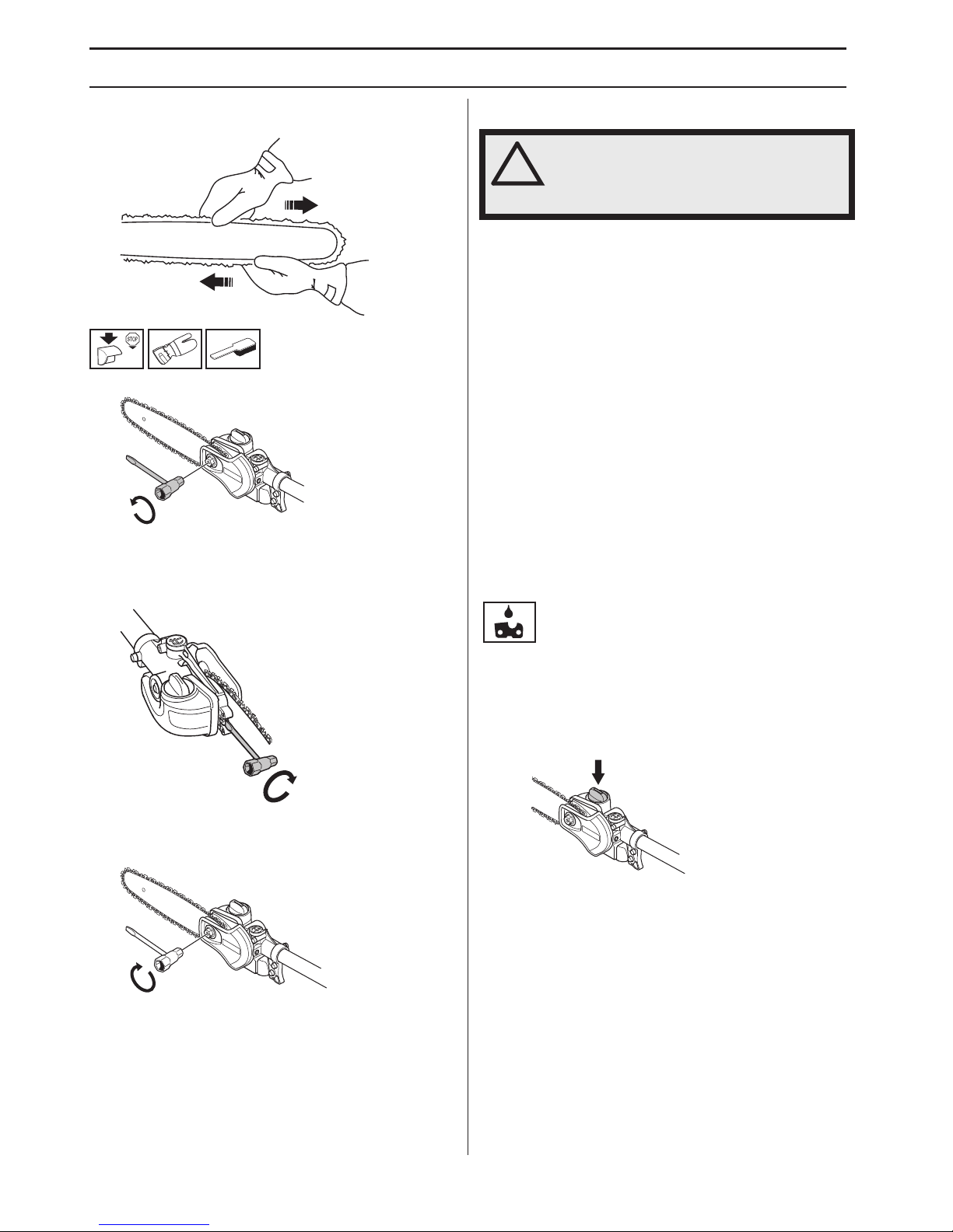
• Tension the chain as tightly as possible, but not so
tight that you cannot pull it round freely by hand.
1 Undo the bar nut.
2 Raise the tip of the bar and stretch the chain by
tightening the chain tensioning screw using the
combination spanner. Tighten the chain until it does
not sag from the underside of the bar.
3 Use the combination spanner to tighten the blade nut
while holding up the tip of the bar. Check that you can
pull the saw chain round freely by hand.
Lubricating cutting equipment
Chain oil
• Chain oil must demonstrate good adhesion to the
chain and also maintain its flow characteristics
regardless of whether it is warm summer or cold
winter weather.
• As a chain saw manufacturer we have developed an
optimal chain oil which, with its vegetable oil base, is
also biodegradable. We recommend the use of our
own oil for both maximum chain life and to minimise
environmental damage.
• If our own chain oil is not available, standard chain oil
is recommended.
• In areas where oil specifically for lubrication of saw
chains is unavailable, ordinary EP 90 transmission oil
may be used.
• Never use waste oil! This is dangerous for yourself,
the machine and the environment.
Filling with chain oil
The oil pump is preset at the factory to meet most
lubrication requirements. A full oil tank will last about half
as long as a full tank of fuel. You should therefore check
the level of oil in the oil tank regularly to avoid damage to
the saw chain and bar that could occur due to lack of
lubrication.
!
WARNING! Poor lubrication of cutting
equipment may cause the chain to snap,
which could lead to serious, even fatal
injuries.
Page 11
SAFETY INSTRUCTIONS
English – 11
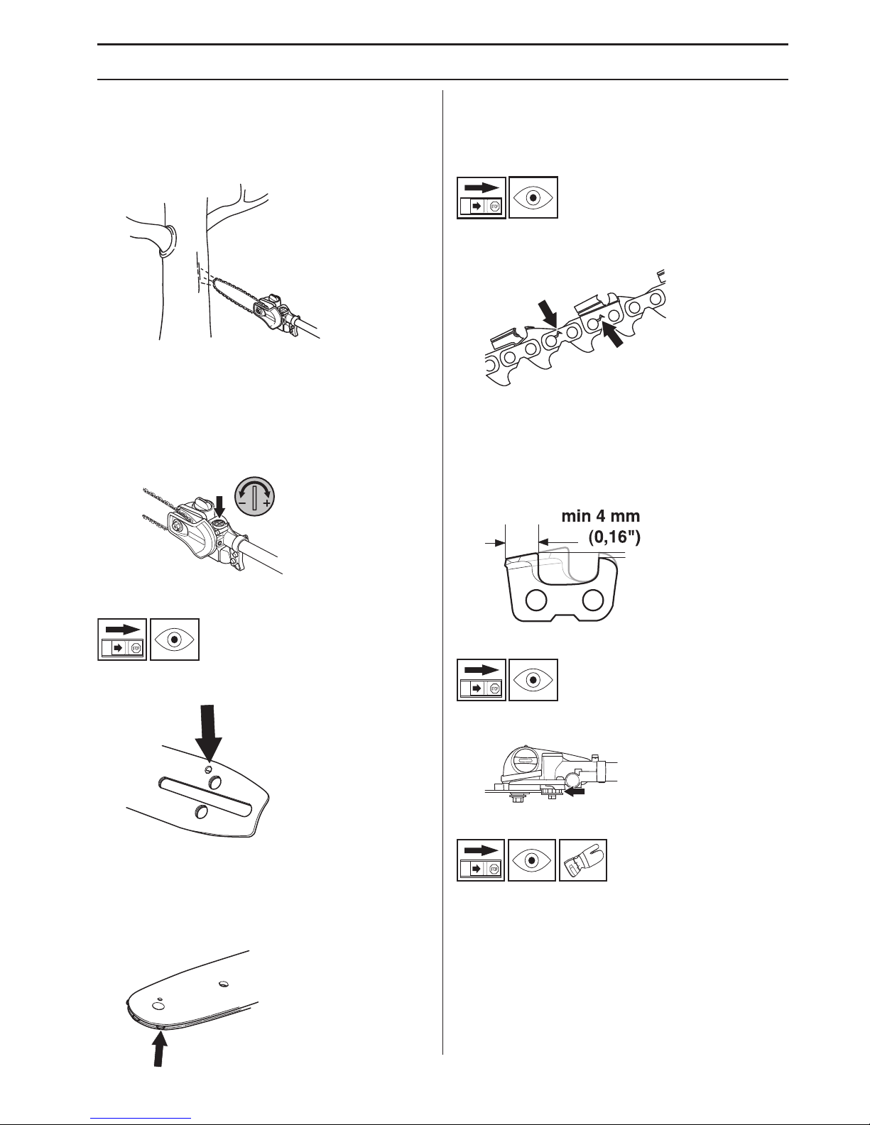
Checking chain lubrication
Check the chain lubrication each time you refuel. Aim the
tip of the bar at a light coloured surface about 20 cm (8
inches) away. After 1 minute running at 3/4 throttle you
should see a distinct line of oil on the light surface.
Adjusting chain lubrication
When cutting dry or hard species of wood it may be
necessary to increase lubrication. Turn the adjuster screw
anticlockwise to increase the oil flow. Remember that this
will increase oil consumption, check the level in the oil
tank regularly. Turn the adjuster screw clockwise to
decrease the oil flow.
What to do if lubrication does not work:
1 Check that the oil channel in the bar is not obstructed.
Clean if necessary.
2 Check that the oil channel in the gear housing is
clean. Clean if necessary.
3 Check that the bar tip sprocket turns freely. If the chain
lubrication system is still not working after carrying out
the above checks you should contact your service
workshop.
Checking wear on cutting
equipment
Saw chain
Check the chain daily for:
• Visible cracks in rivets and links.
• Whether the chain is stiff.
• Whether rivets and links are badly worn.
We recommend you compare the existing chain with a
new chain to decide how badly the existing chain is worn.
When the length of the cutting teeth has worn down to
only 4 mm the chain must be replaced.
Chain drive sprocket
Regularly check the degree of wear on the drive sprocket.
Replace if wear is excessive.
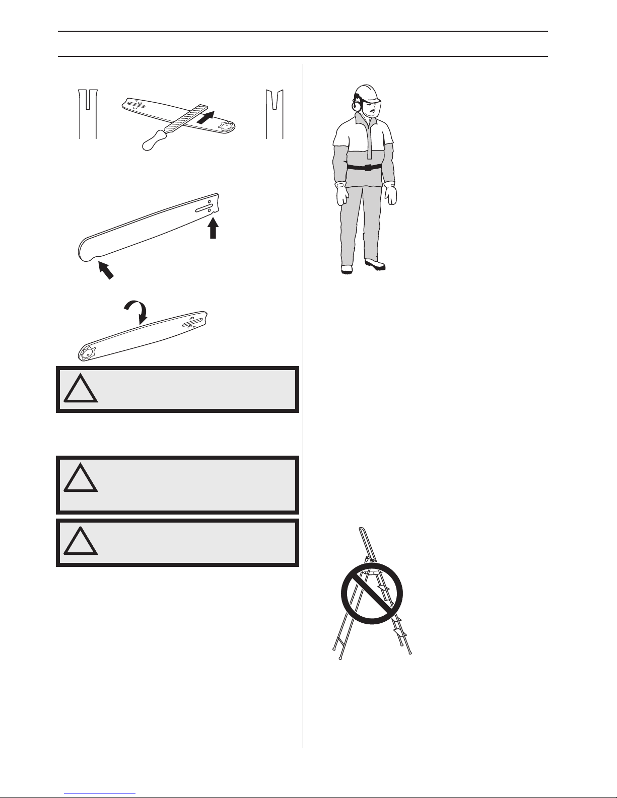
Guide bar
Check regularly:
• Whether there are burrs on the edges of the bar.
Remove these with a file if necessary.
Page 12
SAFETY INSTRUCTIONS
12 – English
• Whether the groove in the bar has become badly
worn. Replace the bar if necessary.
• Whether the tip of the bar is uneven or badly worn. If
a hollow forms on the underside of the bar tip this is
due to running with a slack chain.
To prolong the life of the bar you should turn it over daily.
Safety instructions for using a
pruning saw
CAUTION! Please read the operator’s manual carefully
and make sure you understand the instructions before
using the machine.
Personal protection
• Always wear boots and other equipment described
under the heading Personal protective equipment in
the machine’s Operator’s Manual.
• Always wear working clothes and heavy-duty long
trousers.
• Never wear loose clothing or jewellery.
• Make sure your hair does not hang below shoulder
level.
Safety instructions regarding the
surroundings
• Never allow children to use the machine.
• Ensure that no-one comes closer than 15 metres
while you are working.
• Never allow anyone else to use the machine without
first ensuring that they have read and understood the
contents of the operator’s manual.
• Never work from a ladder, stool or any other raised
position that is not fully secured.
!
WARNING! A faulty cutting attachment
may increase the risk of accidents.
!
WARNING! The machine can cause
serious personal injury. Read the safety
instructions carefully. Learn how to use
the machine.
!
WARNING! Cutting tool. Do not touch the
tool without first switching off the
engine.
Page 13

SAFETY INSTRUCTIONS
English – 13
Safety instructions while working
• Always ensure you have a safe and stable working
position.
• Always use both hands to hold the machine. Hold the
machine at the side of your body.
• Use your right hand to control the throttle setting.
• Make sure that your hands and feet do not come near
the cutting attachment when the engine is running.
• When the engine is switched off, keep your hands and
feet away from the cutting attachment until it has
stopped completely.
• Watch out for stumps of branches that can be thrown
out during cutting.
• Always lay the machine on the ground when you are
not using it.
• Check the working area for foreign objects such as
electricity cables, insects and animals, etc, or other
objects that could damage the cutting attachment,
such as metal items.
• If any foreign object is hit or if vibrations occur stop the
machine immediately. Disconnect the HT lead from
the spark plug. Check that the machine is not
damaged. Repair any damage.
• If anything gets caught up in the cutting attachment
while you are working, switch off the engine and let it
stop completely before cleaning the cutting
attachment.
Safety instructions after completing work
• The transport guard should always be fitted to the
cutting attachment when the machine is not in use.
• Make sure the cutting attachment has stopped before
cleaning, carrying out repairs or an inspection.
Disconnect the spark plug cap from the spark plug.
• Always wear heavy-duty gloves when repairing the
cutting attachment. This is extremely sharp and can
easily cause cuts.
• Store the machine out of reach of children.
• Use only original spare parts for repairs.
Basic working techniques
• Hold the machine as close to your body as possible to
get the best balance.
• Make sure that the tip does not touch the ground.
• Do not rush the work, but work steadily until all the
branches have been cut back cleanly.
• Always slow the engine to idle speed after each
working operation. Long periods at full throttle without
any load on the engine can lead to serious engine
damage.
• Always work at full throttle.
Observe great care when working close to overhead
power lines. Falling branches can result in short-circuiting.
!
WARNING! Never stand directly
underneath a branch that is being cut.
This could lead to serious or even fatal
personal injury.
!
WARNING! Observe the applicable safety
regulations for work in the vicinity of
overhead power lines.
Page 14
SAFETY INSTRUCTIONS
14 – English
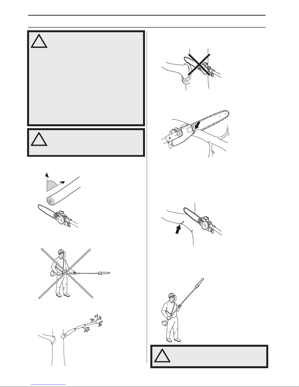
• Whenever possible position yourself so that you can
make the cut at right angles to the branch.
• Do not work with the shaft held straight out in front of
you (like a fishing rod) as this increases the apparent
weight of the cutting attachment.
• Cut large branches in sections so that you have better
control over where they fall.
• Never cut through the swelling at the root of the
branch as this will slow down healing and increase the
risk of fungal attack!
• Use the stop at the base of the cutting head to provide
support during cutting. This will help prevent the
cutting attachment from ”jumping” on the branch.
• Make an initial cut on the underside of the branch
before cutting through the branch. This will prevent
tearing of the bark, which could lead to slow healing
and cause permanent damage to the tree. The cut
should not be deeper than 1/3 of the branch thickness
to prevent jamming. Keep the chain running while you
withdraw the cutting attachment from the branch to
prevent it jamming.
• Use the harness to support the weight of the machine
and make it easier to handle.
• Make sure you have a firm footing and that you can
work without being hampered by branches, stones
and trees.
!
WARNING! This machine is not electrically
insulated. If the machine touches or
comes close to high-voltage power lines it
could lead to death or serious bodily
injury. Electricity can jump from one point
to another by arcing. The higher the
voltage, the greater the distance
electricity can jump. Electricity can also
travel through branches and other
objects, especially if they are wet. Always
keep a distance of at least 10 m between
the machine and high-voltage power lines
and/or any objects that are touching them.
If have to work within this safe distance
you should always contact the relevant
power company to make sure the power is
switched off before you start work.
!
WARNING! This machine has a long
reach. Make sure that no people or
animals come closer than 15 m when the
machine is running.
90°
!
WARNING! Never activate the throttle
without having the cutting attachment in
full view.
Page 15
ASSEMBLY
English – 15
Fitting the cutting head
• Fit the cutting head on the shaft so that the screw (A)
is aligned with the hole in the shaft as shown.
• Tighten screw A.
• Tighten screw B.
CAUTION! Make sure that the drive shaft inside the shaft
engages with the cut-out in the cutting head.
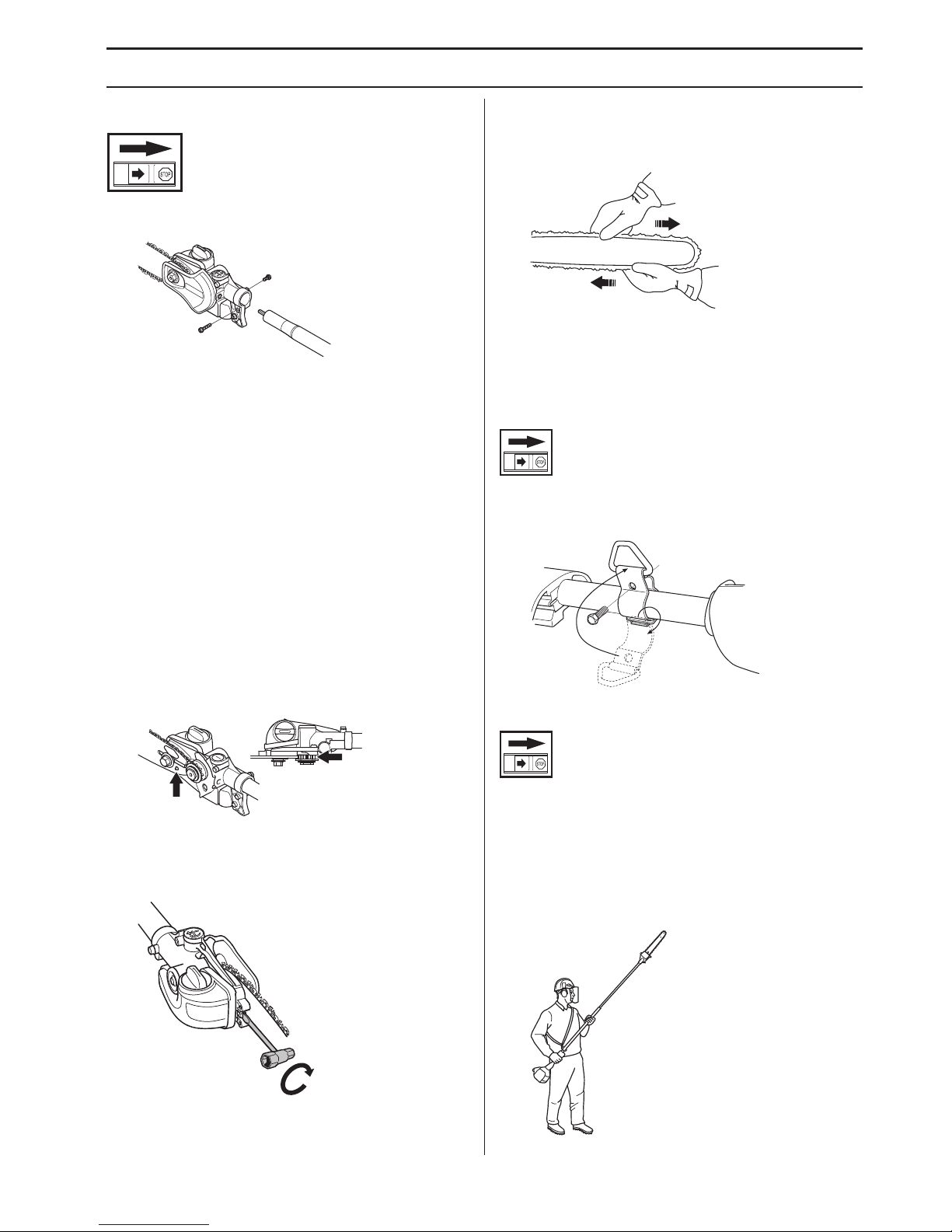
Fitting the bar and chain
• Unscrew the bar nut and remove the protective cover.
• Fit the bar over the bar bolt. Place the bar in its
rearmost position. Place the chain over the drive
sprocket and in the groove on the bar. Begin on the top
side of the bar.
• Make sure that the edges of the cutting links are facing
forward on the top edge of the bar.
• Fit the cover and locate the chain adjuster pin (A) in
the hole in the bar. Check that the drive links of the
chain fit correctly on the drive sprocket (B) and that the
chain is in the groove in the bar (C). Tighten the bar
nut finger-tight.
• Tension the chain by turning the chain tensioning
screw clockwise using the combination spanner. The
chain should be tensioned until it does not sag from
the underside of the bar.
• The chain is correctly tensioned when it does not sag
from the underside of the bar, but can still be turned
easily by hand. Hold up the bar tip and tighten the bar
nuts with the combination spanner.
• When fitting a new chain, the chain tension has to be
checked frequently until the chain is run-in. Check the
chain tension regularly. A correctly tensioned chain
ensures good cutting performance and long life.
Fitting the suspension ring
Fit the suspension ring between the rear handle and the
loop handle. Position the hanging ring so that the machine
is balanced and comfortable to work with.
Adjusting the harness
You should always use the harness with the machine to
give maximum control over the machine and reduce the
risk of fatigue in your arms and back.
• Put on the harness.
• Hook the machine onto the harness support hook.
• Adjust the length of the harness so that the support
hook is roughly level with your right hip.
A
B
A
B
Page 16
ASSEMBLY
16 – English
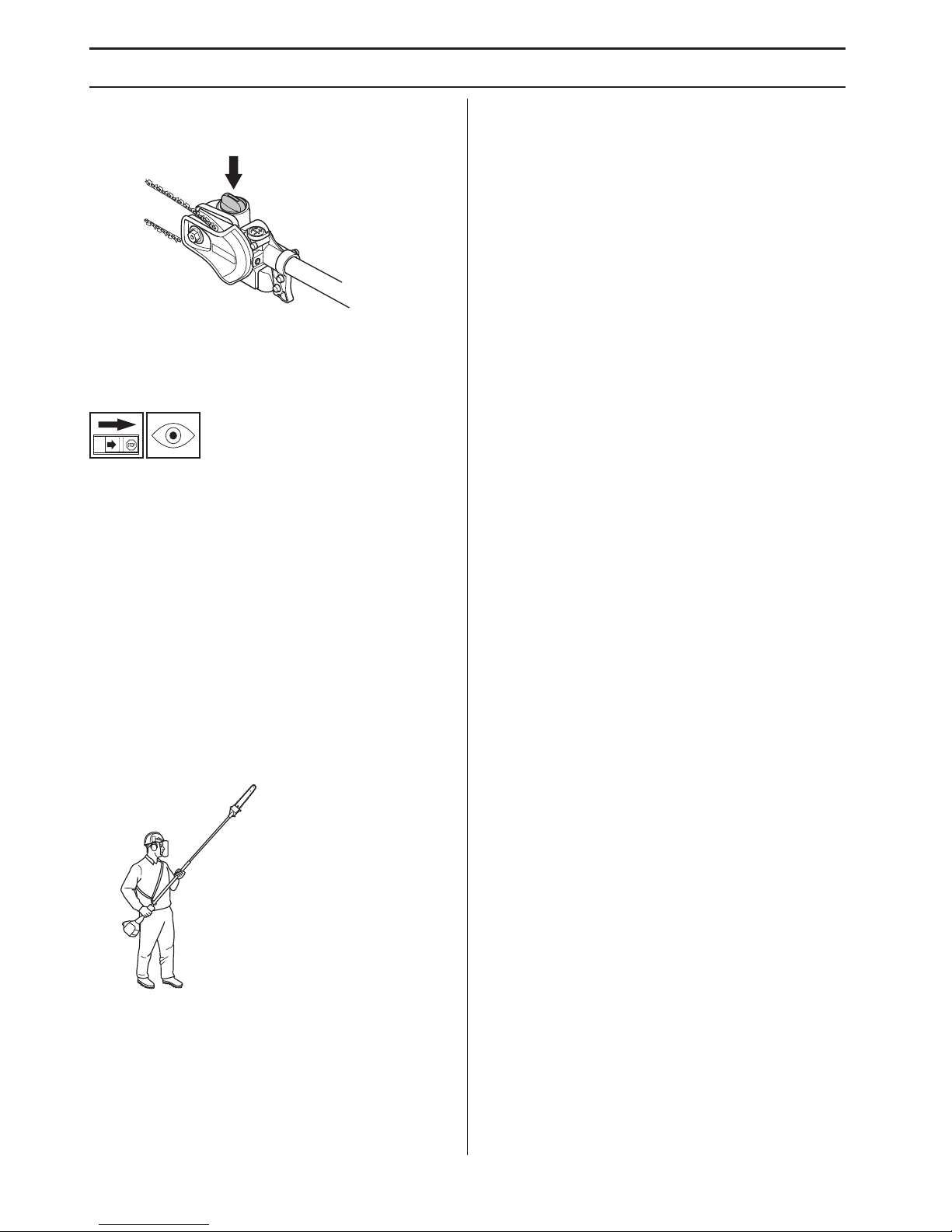
Filling with oil
• Open the cap on top of the bar head
• Fill with Husqvarna saw chain oil.
•Refit the cap.
Check before starting
• Inspect the working area. Remove any objects that
could be thrown out.
• Check the cutting attachment. Never use blunt,
cracked or damaged equipment.
• Check that the machine is in perfect working order.
Check that all nuts and screws are tight.
• Make sure the chain is adequately lubricated. See
instructions under the heading Lubricating the cutting
attachment.
• Check that the cutting attachment always stops when
the engine is idling.
• Only use the machine for the purpose it was intended
for.
• Make sure the handle and safety features are in order.
Never use a machine that has any parts missing or
has been modified in relation to the specification.
Page 17
English – 17
TECHNICAL DATA
Technical data
Note 1 Noise emissions in the environment measured as sound power (LWA) in conformity with EC directive 2000/14/
EC. Reported sound power level for the machine has been measured with the original cutting attachment that gives the
highest level. The difference between guaranteed and measured sound power is that the guaranteed sound power also
includes dispersion in the measurement result and the variations between different machines of the same model
according to Directive 2000/14/EC.
Note 2: Reported data for equivalent sound pressure level for the machine has a typical statistical dispersion (standard
deviation) of 1 dB (A).
Note 3: Reported data for equivalent vibration level has a typical statistical dispersion (standard deviation) of 1 m/s2.
Guide bar and saw chain combinations
The following combinations are CE approved.
Technical data Saw attachment with shaft PA 1100
Lubrication system
Oil tank capacity, litre 0,15
Weight
Weight without fuel, cutting attachment and guard, kg 1,4
Noise emissions (see note 1)
Sound power level, measured dB (A) 110
Sound power level, guaranteed LWA dB (A) 111
Sound levels (see note 2)
Equivalent sound pressure level at the operator’s ear, measured according to
EN ISO 11806 and ISO 22868, dB(A):
Equipped with approved accessory (original) 94
Vibration levels (see note 3)
Vibration levels at handles, measured according to EN ISO 22867, m/s
2
Equipped with approved accessory (original), left/right 3,5/4,6
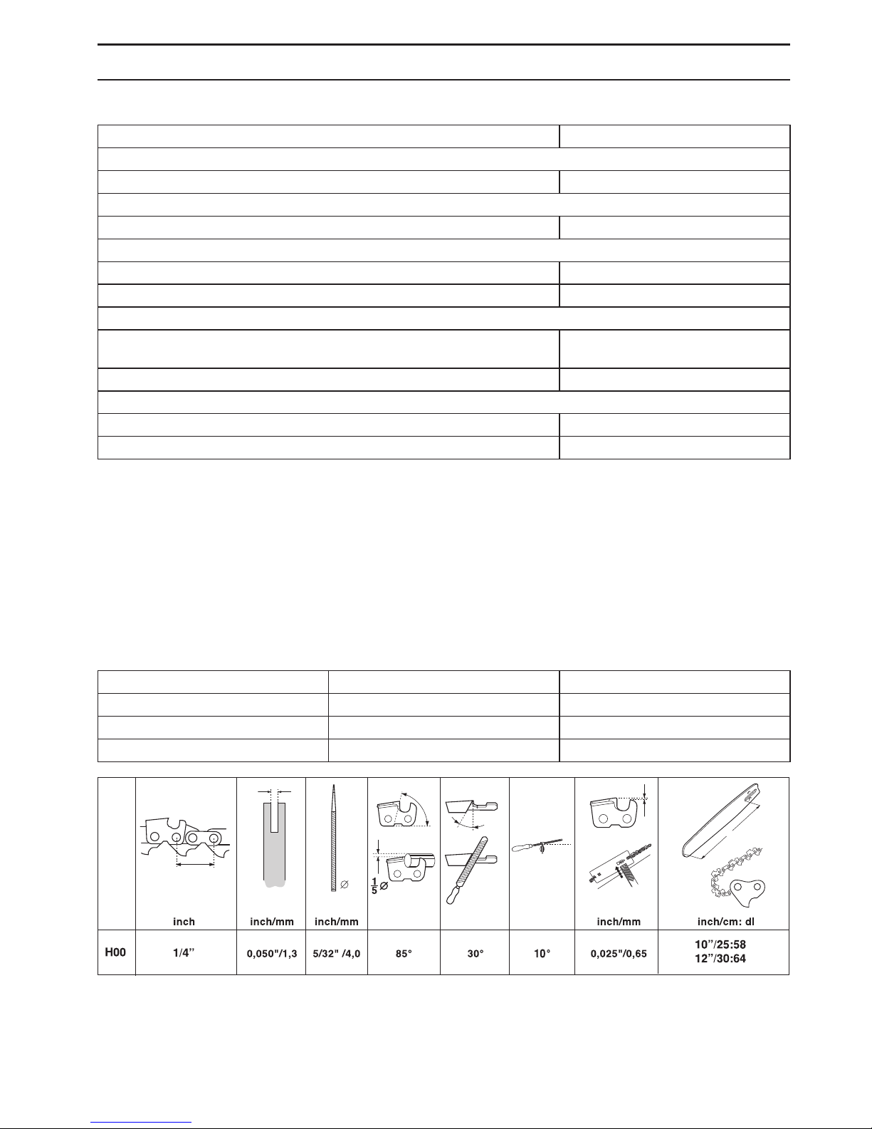
Guide bar Saw chain
Length, inch Pitch, inch
10 1/4 Husqvarna H00
12 1/4
D
2
L
_
D
PITCH =
Page 18

18 – English
TECHNICAL DATA
EC Declaration of Conformity (Applies to Europe only)
We, Husqvarna AB, SE-561 82 Huskvarna, Sweden, tel +46-36-146500, declare that this saw attachment from 2014’s
serial numbers and onwards (the year is clearly stated in plain text on the type plate, with subsequent serial number),
complies with the requirements of the COUNCIL’S DIRECTIVE:
of May 17, 2006 ”relating to machinery” 2006/42/EC.
The following standards have been applied: EN ISO 12100:2010, ISO 11680-1:2011
Notified body: 0404, SMP Svensk Maskinprovning AB, Box 7035, SE-750 07 Uppsala, Sweden, has carried out EC
type examination in accordance with the machinery directive’s (2006/42/EC) article 12, point 3b. The certificates for EC
type examination in accordance with annex VI, have the numbers:
0404/14/2394
Huskvarna 13 March, 2014
Per Gustafsson, Development manager
(Authorized representative for Husqvarna AB and responsible for technical documentation.)
Page 19
SIMBOLOGIA
Italian – 19
Simboli
AVVERTENZA! Se utilizzata in modo
improprio o non corretto, la macchina
può essere un attrezzo pericoloso in
grado di provocare gravi lesioni o morte
dell’operatore , o di altre persone.
Prima di usare la macchina,
leggere per intero le istruzioni per
l’uso e accertarsi di averne
compreso il contenuto.
Usare sempre:
• Casco di protezione laddove
sussiste il rischio di caduta di oggetti
• Protezioni acustiche omologate
• Occhiali o visiera di protezione
Il presente prodotto è conforme alle
vigenti direttive CEE.
Questa macchina non è isolata
elettricamente. Se la macchina
viene a trovarsi a contatto o
nelle vicinanze di cavi
conduttori di tensione si può
incorrere in lesioni gravi o
mortali. L’elettricità può essere
condotta da un punto all’altro
tramite un cosiddetto arco di
tensione. Più la tensione è alta,
maggiore è lo spazio attraverso
il quale è possibile condurre l’elettricità. L’elettricità può
anche essere condotta tramite rami o altri oggetti,
particolarmente se bagnati. Mantenere sempre una
distanza di almeno 10 m fra la macchina e il cavo
conduttore di tensione e/o l’oggetto che si trova a contatto
con esso. Se siete obbligati a lavorare con una distanza di
sicurezza inferiore, contattare sempre l’azienda
distributrice dell’energia per assicurarvi che la tensione
sia staccata al momento in cui date inizio al lavoro.
Utilizzare sempre guanti protettivi
omologati.
Usare stivali robusti e antisdrucciolo.
I restanti simboli/decalcomanie riguardano
particolari requisiti necessari per ottenere la
certificazione in alcuni mercati.
Il controllo e/o la manutenzione
vanno eseguiti a motore spento, con
il pulsante di arresto in posizione
STOP.
Utilizzare sempre guanti protettivi
omologati.
E’ necessario pulire con regolarità.
Controllo visivo.
Usare sempre occhiali o visiera di
protezione.
Rifornimento e regolazione del flusso
dell’olio
Page 20
INDICE
20 – Italian
Indice Prima dell’avviamento osservare
quanto segue:
La Husqvarna AB procede costantemente allo sviluppo
dei propri prodotti e si riserva quindi il diritto di apportare,
senza alcun preavviso, modifiche riguardanti fra l’altro la
forma e l’aspetto esteriore.
Una lunga esposizione al rumore può comportare lesioni
permanenti all'udito. Usare quindi sempre cuffie di
protezione omologate.
Prima di usare la macchina, leggere per intero le istruzioni
per l’uso e accertarsi di averne compreso il contenuto.
Il presente libretto integra le istruzioni per l’uso allegate
alla macchina. Per le altre funzioni, vedere il libretto di
istruzioni per l’uso della macchina.
La macchina è costruita esclusivamente per il taglio di
rami e ramoscelli.
SIMBOLOGIA
Simboli .................................................................. 19
INDICE
Indice .................................................................... 20
Prima dell’avviamento osservare quanto segue: .. 20
INTRODUZIONE
Alla gentile clientela .............................................. 21
CHE COSA C’È?
Cosa c’è nell’accessorio motosega? .................... 22
NORME DI SICUREZZA
Attrezzatura di taglio ............................................. 23
Specifiche relative a lama e catena ...................... 23
Affilatura della catena e controllo della profondità
di taglio .................................................................
24
Tensionamento della catena ................................. 26
Lubrificazione dell’attrezzatura di taglio ................ 27
Controllo dell’usura dell’attrezzatura di taglio ....... 28
Norme di sicurezza per l’uso di motosega ad asta 29
MONTAGGIO
Montaggio testina di taglio .................................... 32
Montaggio di lama e catena .................................. 32
Montaggio del gancio di sospensione ................... 32
Impostazione dell’imbracatura .............................. 33
Rabbocco dell’olio ................................................. 33
Controlli prima dell’avviamento ............................. 33
CARATTERISTICHE TECNICHE
Caratteristiche tecniche ........................................ 34
Combinazioni di lama e catena ............................. 34
Dichiarazione di conformità CE ............................ 35
!
AVVERTENZA! Evitare assolutamente di
modificare la versione originale della
macchina senza l’autorizzazione del
fabbricante. Usare sempre accessori
originali. Modifiche e/o accessori non
autorizzati possono causare lesioni gravi
o mortali all’operatore o a terzi.
!
AVVERTENZA! Questo accessorio può
essere usato solo con alcuni tipi di
decespugliatori/bordatori appositamente
studiati (vedere alla voce ”Accessori
omologati”, al capitolo Dati Tecnici, nel
manuale delle istruzioni della macchina).
Page 21

Italian – 21
INTRODUZIONE
Alla gentile clientela
Congratulazioni per aver scelto di acquistare un prodotto Jonsered!
Siamo convinti che sarete pienamente soddisfatti della qualità e delle prestazioni del nostro prodotto per un lungo tempo
a venire. L'acquisto di uno dei nostri prodotti vi garantisce l'accesso alla competenza di personale qualificato per
l'assistenza e le riparazioni in caso di necessità. Se non avete acquistato la macchina presso uno dei nostri rivenditori
autorizzati, rivolgetevi alla più vicina officina di assistenza.
Ci auguriamo che rimarrete soddisfatti della vostra macchina e speriamo di potervi servire per molto tempo in futuro.
Non dimenticate che questo manuale delle istruzioni è un documento di valore. Seguendone il contenuto (uso,
assistenza, manutenzione ecc.) potrete aumentare notevolmente la durata della vostra macchina e anche il suo valore
di usato. Se vendete la macchina, ricordate di consegnare il manuale delle istruzioni al nuovo proprietario.
Buona fortuna nell’uso del vostro prodotto Jonsered!
La Jonsered procede costantemente allo sviluppo dei propri prodotti e si riserva quindi il diritto di apportare, senza alcun
preavviso, modifiche riguardanti fra l’altro la forma e l’aspetto esteriore.
Page 22
22 – Italian
CHE COSA C’È?
Cosa c’è nell’accessorio motosega? (Accessorio motosega con albero cavo PA 1100)
4
13
12
14
15
10
11
2
7
11
9
1
2
8
6
5
3
16
1 Riduttore angolare
2 Vite di regolazione lubrificazione catena
3 Albero cavo (1100 mm)
4 Gancio di sospensione imbracatura
5 Coperchio di protezione catena
6 Dado della lama
7 Vite tendicatena
8 Catena
9 Lama
10 Contenitore olio per catena
11 Rifornimento dell’olio per catena
12 Istruzioni per l’uso
13 Protezione per trasporto
14 Chiave combinata
15 Imbracatura
16 Chiave Torx
Page 23

NORME DI SICUREZZA
Italian – 23
Attrezzatura di taglio
Questo capitolo descrive come, eseguendo una
manutenzione corretta ed usando il giusto tipo di gruppo
di taglio, è possibile ottenere la massima capacità di
abbattimento e prolungare la durata del gruppo di taglio.
Usare solo attrezzatura di taglio da noi consigliata!
Vedi istruzioni alla voce Caratteristiche tecniche.
Tenere sempre ben affilati i denti della catena!
Seguire le istruzioni e usare i riscontri raccomandati.
Se la catena non è ben affilata, aumenta il rischio di
incidenti.
Mantenere una corretta profondità di taglio! Seguire
le istruzioni e usare la dima di riscontro
raccomandata.
Una profondità di taglio eccessiva
aumenta il rischio di contraccolpo.
Controllare la tensione della catena! Una catena
troppo lenta salta facilmente e aumenta l’usura di ruota di
rinvio, lama e catena.
Curare la lubrificazione e la manutenzione
dell’attrezzatura di taglio!
Una lubrificazione
insufficiente aumenta il rischio di rottura della catena e di
usura di ruota di rinvio, lama e catena.
Specifiche relative a lama e
catena
Quando il gruppo di taglio in dotazione alla vostra
macchina è usurato o danneggiato e dev’essere
sostituito, usare esclusivamente i tipi di lama e catena da
noi raccomandati.
Lama
• Lunghezza (pollici/cm)
!
AVVERTENZA! Non usare mai una
macchina con dispositivi di sicurezza
guasti. Questi dispositivi vanno
controllati e sottoposti a manutenzione
secondo quanto descritto in questo
capitolo. Se la macchina non supera tutti
i controlli, contattare un’officina per le
necessarie riparazioni.
!
AVVERTENZA! Spegnere sempre il
motore prima di eseguire qualsiasi
operazione sul gruppo di taglio. Questo
infatti continua a ruotare anche quando
l’acceleratore viene rilasciato. Accertarsi
che il gruppo di taglio sia completamente
fermo e staccare il cavo dalla candela
prima d’iniziare qualunque operazione.
Page 24

NORME DI SICUREZZA
24 – Italian
• Partitura della catena (pollici). La rotella di punta della
lama e l’ingranaggio di trascinamento della catena
devono essere adeguati alla distanza tra le maglie di
trascinamento.
• Numero di maglie di trascinamento (pz). Ogni
lunghezza di lama, unita alla partitura della catena e
ai denti della rotella di punta, risulta in un preciso
numero di maglie di trascinamento.
• Larghezza della guida della lama (pollici/mm). La
larghezza della guida della lama deve essere
adeguata alla larghezza delle maglie di
trascinamento.
• Foro di lubrificazione della catena e foro del perno
tendicatena.
Catena
•
Partitura (pollici). (Distanza tra tre maglie divisa per due.)
• Larghezza della maglia di trascinamento (mm/pollici)
• Numero di maglie di trascinamento (pz)
Affilatura della catena e controllo
della profondità di taglio
Generalità sull’affilatura della catena
• La catena deve essere sempre ben affilata. Se la
catena non taglia senza dover premere la lama contro
il legno e produce segatura molto fine, è segno che
non è affilata bene. Se il taglio non produce segatura,
la catena ha perso completamente il filo e nel tagliare
polverizza il legno.
• Se la catena è affilata, avanza da sola nel legno e
produce trucioli grossi e lunghi. La parte tagliente
della catena è costituita dalla maglia di taglio, con un
dente (A) e una punta per la profondità di taglio (B). Il
dislivello tra questi determina la profondità di taglio.
!
AVVERTENZA! Se la catena non è affilata
aumenta il rischio di contraccolpo!
Page 25

NORME DI SICUREZZA
Italian – 25
• Per l’affilatura del dente di taglio vanno considerate 5
misure.
1 Angolo di affilatura
2 Angolo di appoggio
3 Posizione della lima
4 Diametro della lima tonda
5 Profondità di affilatura
E’ difficile affilare correttamente una catena senza gli
strumenti necessari. Raccomandiamo perciò l’uso dei
nostri blocchetti di riscontro. Essi garantiscono
un’affilatura che riduce al minimo il contraccolpo e
permette la massima capacità di taglio.
Affilatura dei denti
• Per ottenere una buona affilatura della catena
servono un riscontro e una lima tonda.
• Controllare che la catena sia ben tesa. In caso
contrario la catena si muove lateralmente ed è più
difficile ottenere una corretta affilatura.
•Affilare sempre il dente di taglio dall’interno verso
l’esterno. Allentare la pressione sulla lima in fase di
1
5
!
AVVERTENZA! Le seguenti deviazioni
dalle istruzioni per l’affilatura aumentano
considerevolmente la tendenza al
contraccolpo della motosega: Angolo di
affilatura eccessivo
Angolo di affilatura insufficiente
Diametro della lima insufficiente
Page 26

NORME DI SICUREZZA
26 – Italian
ritorno. Affilare prima tutti i denti di un lato della lama.
Girare ed affilare poi i denti restanti sull’altro lato.
•Affilare facendo in modo che tutti i denti siano di
uguale lunghezza. Quando il dente di taglio è di soli 4
mm (5/32"), la catena è usurata e va rottamata.
Generalità sulla profondità di taglio
• Con l’affilatura dei denti diminuisce la profondità di
taglio. Per mantenere la massima capacità di taglio è
necessario abbassare il bordo del raschiatoio al livello
consigliato.
• Su un dente di taglio con riduzione del contraccolpo la
parte anteriore della punta della profondità di taglio è
stondata. È indispensabile mantenere questa
configurazione dopo aver regolato la profondità di
taglio.
• Si consiglia di usare la nostra dima di riscontro che
fornisce la corretta profondità di taglio e permette di
regolare anche la smussatura della punta.
Regolazione della profondità di taglio
• Prima di controllare la profondità di taglio, la catena
deve essere affilata. Si consiglia di effettuare questo
controllo ogni tre affilature della catena. N.B! Questa
raccomandazione presuppone che i denti siano stati
sottoposti ad una affilatura normale.
• La regolazione della profondità di taglio viene
effettuata con una lima piatta e una dima di riscontro.
• Porre la dima sulla punta.
• Appoggiare la lima piatta sulla parte in eccesso della
punta ed eliminare l’eccesso. L’operazione è conclusa
quando la lima passa sulla dima senza incontrare
resistenza.
Tensionamento della catena
• La lunghezza della catena aumenta con l’uso. È
importante quindi regolare l’attrezzatura di taglio in
seguito a cambiamenti del genere.
!
AVVERTENZA! Una profondità di taglio
eccessiva aumenta la propensione della
catena al contraccolpo!
!
AVVERTENZA! Una catena troppo lente
salta facilmente, e rappresenta motivo di
pericolo in quanto può provocare lesioni
gravi o mortali.
Page 27

NORME DI SICUREZZA
Italian – 27
• Controllare spesso la tensione della catena, meglio se
ad ogni occasione di rifornimento. N.B! Se la catena è
nuova, richiede un periodo di rodaggio durante il
quale va controllata più spesso.
• Tendere la catena il più possibile, ma in modo che
possa essere facilmente fatta girare con la mano.
1 Allentare il dado della lama.
2 Sollevare la punta della lama e tirare la catena
avvitando la vite del tendicatena con l’utensile
combinato. Tendere la catena fino a quando non
rimane nella scanalatura intorno alla lama.
3 Stringere il dado della lama con la chiave combinata
tenendo sollevata la punta della lama. Controllare che
la catena possa essere fatta girare manualmente con
facilità.
Lubrificazione dell’attrezzatura di
taglio
Olio per catena
• L’olio per catena deve presentare una buona
aderenza e buone proprietà di scorrimento, sia
d’estate che d’inverno.
• In qualità di produttori di motoseghe abbiamo messo
a punto un olio per catena ottimale e, grazie alla base
vegetale, biodegradabile. Consigliamo l’utilizzo del
nostro olio per assicurare la massima durata della
motosega e tutelare l’ambiente.
• Qualora il nostro olio per catena non fosse disponibile,
utilizzare un comune olio per catene.
• Nelle zone in cui non sono disponibili oli studiati
appositamente per la lubrificazione della catena è
possibile utilizzare olio per trasmissioni EP 90.
• Non utilizzare mai oli esausti! Questi oli sono nocivi
per voi, la macchina e l’ambiente.
Rifornimento dell’olio per catena
La pompa dell’olio è registrata in fabbrica per far fronte
alla maggior parte delle necessità di lubrificazione. Un
rifornimento d’olio completo ha una durata pari a circa la
metà della durata di un rifornimento di benzina.
Controllare quindi regolarmente la quantità d’olio nel
serbatoio per evitare danni alla catena e alla lama che
potrebbero venir causati da una mancata lubrificazione.
!
AVVERTENZA! Una lubrificazione
insufficiente dell’attrezzatura di taglio
provoca la rottura della catena con gravi
rischi di lesioni personali anche mortali.
Page 28

NORME DI SICUREZZA
28 – Italian
Controllo della lubrificazione della catena
Controllare il funzionamento della lubrificazione ad ogni
rifornimento. Puntare la lama contro una superficie
chiara, da una ventina di centimetri (8 pollici) di distanza.
Dopo un minuto circa, a 3/4 di gas, la superficie dovrà
presentare evidenti tracce d’olio.
Regolazione della lubrificazione della catena
In caso di operazioni su legname duro e secco può
essere necessario aumentare la lubrificazione. Il flusso
d'olio aumenta girando la vite di regolazione in senso
antiorario. Ricordare che in questo modo il flusso d'olio
aumenta, controllare quindi regolarmente la quantità
d'olio nel serbatoio. Il flusso d'olio diminuisce girando la
vite di regolazione in senso orario.
Misure in caso di mancato funzionamento
della lubrificazione:
1 Controllare che il canale di lubrificazione della lama
non sia ostruito. Pulire se necessario.
2 Controllare che il canale di lubrificazione della scatola
del cambio sia pulito. Pulire se necessario.
3 Controllare che la rotella di punta della lama giri
liberamente. Se la lubrificazione della catena non
funziona nonostante gli interventi summenzionati
contattare l’officina per l’assistenza.
Controllo dell’usura
dell’attrezzatura di taglio
Catena
Controllare giornalmente la catena, ed in particolare:
• Presenza di fratture o lesioni sui perni o sulle maglie.
• Elasticità della catena.
• Usura inconsueta di maglie e denti.
Per riferimento usare una catena nuova.
Quando la lunghezza del dente di taglio è di soli 4 mm,
sostituire la catena con una nuova.
Rotella di trascinamento della catena
Controllare regolarmente il livello di usura della rotella di
trascinamento. Sostituire se necessario.
Lama
Controllare con regolarità:
• La presenza di graffi sui lati della lama. Eliminare con
una lima se necessario.
• Se la scanalatura della lama è usurata oltre il normale.
Sostituire la lama se necessario.
Page 29

NORME DI SICUREZZA
Italian – 29
• Se la punta della lama è usurata irregolarmente. In
caso di formazione di un ”affossamento” alla fine della
curvatura della punta, la catena non è correttamente
tesa.
Per la massima durata girare la lama giornalmente.
Norme di sicurezza per l’uso di
motosega ad asta
N.B! Prima di usare la macchina, leggere per intero le
istruzioni per l’uso e accertarsi di averne compreso il
contenuto.
Protezione personale
• Indossare sempre stivali e l’attrezzatura descritta alla
voce Abbigliamento protettivo personale nel manuale
delle istruzioni della macchina.
• Utilizzare sempre abiti da lavoro e pantaloni robusti.
• Non indossare mai abiti troppo ampi o gioielli.
• I capelli non devono scendere al di sotto delle spalle.
Norme di sicurezza per l’ambiente
circostante
• Non permettere che la macchina sia utilizzata da
bambini.
• Accertarsi che nessuno si avvicini ad una distanza
inferiore a 15 m durante il lavoro.
• Non consentire mai ad altri l’utilizzo della macchina
senza accertarsi che abbiano capito il contenuto del
manuale di istruzioni.
• Non lavorare mai su una scala, uno sgabello o in altra
posizione sollevata da terra che non sia ben fissata.
Norme di sicurezza durante il lavoro
• Lavorare sempre in posizione sicura e stabile.
• Tenere sempre la macchina con entrambe le mani.
Tenere la macchina lateralmente rispetto al corpo.
• Usare la mano destra per manovrare l’acceleratore.
• Accertarsi che mani e piedi non tocchino il gruppo di
taglio a motore acceso.
• Una volta spento il motore, tenere mani e piedi lontani
dal gruppo di taglio fino al suo completo arresto.
• Fare attenzione ad eventuali ramoscelli che
potrebbero venir lanciati in aria durante l’operazione.
• Appoggiare sempre la macchina a terra durante le
pause.
!
AVVERTENZA! Un gruppo di taglio
inadeguato può aumentare il rischio
d’infortuni.
!
AVVERTENZA! La macchina può
provocare gravi lesioni personali.
Leggere attentamente le norme di
sicurezza. Apprendete l’uso corretto
della macchina.
!
AVVERTENZA! Attrezzo tagliente. Non
toccare l’attrezzo senza aver prima
spento il motore.
Page 30

NORME DI SICUREZZA
30 – Italian
• Esaminare l’oggetto di taglio per escludere la
presenza di corpi estranei, quali cavi elettrici, insetti,
animali ecc., oppure di elementi che potrebbero
danneggiare il gruppo di taglio, ad esempio gli oggetti
metallici.
• In caso di collisione con un oggetto o all’insorgere di
vibrazioni fermare la macchina. Togliere il cavo di
accensione dalla candela. Controllare che la
macchina non presenti danni. Riparare
eventualmente ogni danno riscontrato.
• Nel caso in cui un oggetto dovesse incastrarsi nel
gruppo di taglio durante l’operazione spegnere il
motore e arrestare la macchina completamente fino
all’avvenuta pulizia del gruppo di taglio.
Norme di sicurezza dopo il lavoro
• Quando la macchina non viene usata coprire sempre
il gruppo di taglio con la protezione per il trasporto.
• Accertarsi sempre che il gruppo di taglio si sia fermato
prima di eseguire pulizia, riparazioni o controlli.
Staccare il cavo di accensione dalla candela.
• Usare sempre dei guanti robusti durante la
riparazione del gruppo di taglio. Questo è molto
tagliente e ci si può ferire molto facilmente.
• Conservare la macchina fuori dalla portata dei
bambini.
• Utilizzare esclusivamente ricambi originali per le
riparazioni.
Tecnica fondamentale di lavoro
• Per ottenere un equilibrio ottimale, tenere la macchina
il più possibile vicina al corpo.
• Assicuratevi che la punta non tocchi il terreno.
• Non forzare l’operazione, procedere a velocità
moderata, facendo in modo che tutti i rami vengano
tagliati lasciando una superficie uniforme.
• Dopo ciascuna fase di lavoro decelerare il motore fino
al regime minimo. Un esercizio prolungato a pieno
regime senza carico può causare gravi danni al
motore.
• Lavorare sempre a pieno gas.
Osservare la massima prudenza se si lavora in prossimità
di linee elettriche aeree. I rami che cadono potrebbero
causare un corto circuito.
!
AVVERTENZA! Non sostare mai sotto un
ramo che sta per essere tagliato. Esiste il
rischio di lesioni personali gravi, anche
mortali.
!
AVVERTENZA! In caso di lavori in
prossimità di linee aeree elettriche
osservare le norme di sicurezza vigenti.
!
AVVERTENZA! Questa macchina non è
isolata elettricamente. Se la macchina
viene a trovarsi a contatto o nelle
vicinanze di cavi conduttori di tensione
si può incorrere in lesioni gravi o mortali.
L’elettricità può essere condotta da un
punto all’altro tramite un cosiddetto arco
di tensione. Più la tensione è alta,
maggiore è lo spazio attraverso il quale è
possibile condurre l’elettricità.
L’elettricità può anche essere condotta
tramite rami o altri oggetti,
particolarmente se bagnati. Mantenere
sempre una distanza di almeno 10 m fra
la macchina e il cavo conduttore di
tensione e/o l’oggetto che si trova a
contatto con esso. Se siete obbligati a
lavorare con una distanza di sicurezza
inferiore, contattare sempre l’azienda
distributrice dell’energia per assicurarvi
che la tensione sia staccata al momento
in cui date inizio al lavoro.
!
AVVERTENZA! La macchina ha un raggio
di azione lungo. Accertarsi che non ci
siano persone o animali in un raggio di
15 metri quando la macchina è in
funzione.
Page 31

NORME DI SICUREZZA
Italian – 31
• Cercare la giusta posizione in relazione al ramo di
modo che l’angolo di taglio sia possibilmente di 90º.
• Evitare di lavorare tenendo l’attrezzo diritto davanti a
voi (come una canna da pesca) poiché in questo
modo si avverte maggiormente il peso del gruppo di
taglio.
• Tagliare i rami più spessi in diverse sezioni per avere
un maggior controllo sul luogo in cui andranno a
cadere.
• Non tagliare mai la protuberanza vicina al fusto poiché
essa accelera la cicatrizzazione e ostacola
l’imputridimento!
• Usare la faccia della testina di taglio per appoggiarvi
al ramo durante l’operazione. In questo modo si evita
che il gruppo di taglio ”rimbalzi” sul ramo.
• Praticare un’incisione nella sezione inferiore del ramo
prima di tagliarlo. In questo modo si evitano
sbucciature della corteccia, che potrebbero
danneggiare l’albero in modo permanente o
difficilmente riparabile. L’incisione non deve avere una
profondità superiore ad 1/3 dello spessore del ramo
per evitare inceppature durante il taglio. Staccare
sempre il gruppo di taglio dal ramo con la catena in
movimento per evitare che il gruppo di taglio rimanga
incastrato.
• Usare l’imbracatura per manovrare la macchina più
facilmente e per distribuirne meglio il peso.
• Accertarsi di mantenere una posizione stabile e di
poter lavorare senza venir disturbati da rami, pietre e
alberi.
90°
!
AVVERTENZA! Non accelerare mai senza
avere una visione totale del gruppo di
taglio.
Page 32

MONTAGGIO
32 – Italian
Montaggio testina di taglio
• Montare la testina di taglio sull’albero cavo di modo
che la vite (A) venga a trovarsi al centro rispetto al foro
presente sull’albero cavo, come mostrato nella figura.
• Serrare la vite A.
• Serrare la vite B.
N.B! Accertarsi che l’albero di trasmissione sull’albero
cavo combaci con l’incavo sulla testina.
Montaggio di lama e catena
• Svitare il dado della lama e togliere il coperchio di
protezione.
• Montare la lama sul relativo bullone. Situare la lama il
più indietro possibile. Situare la catena sopra la ruota
motrice e nella scanalatura della lama. Cominciare
dalla parte superiore della lama.
• Controllare che il taglio dei denti sia rivolto in avanti,
sul lato superiore della lama.
• Montare il coperchio e situare il perno tendicatena (A)
nell’incavo della lama. Controllare che le maglie della
catena prendano nella ruota motrice (B) e che la
catena sia al posto giusto nella scanalatura della lama
(C). Serrare con le dita il dado della lama.
• Tendere la catena con la vite apposita e la chiave
combinata avvitandola in senso orario. La tensione è
corretta quando la catena rimane nella scanalatura
intorno alla lama.
• La tensione è corretta quando la catena rimane nella
scanalatura intorno alla lama ed è possibile farla
scorrere con le dita, senza sforzo. Serrare a fondo i
dadi con la chiave combinata tenendo sollevata la
punta della lama.
• Controllare spesso la tensione di una nuova catena
fino al termine del rodaggio. Eseguire il controllo
regolarmente. Una catena correttamente tesa
significa migliori caratteristiche di taglio e lunga
durata.
Montaggio del gancio di
sospensione
Il gancio di sospensione viene montato fra l’impugnatura
posteriore e l’impugnatura ad anello. Situare il gancio in
modo che la macchina sia ben bilanciata e risulti facile da
manovrare.
A
B
A
B
Page 33

MONTAGGIO
Italian – 33
Impostazione dell’imbracatura
Lavorando con la macchina usare sempre l’imbracatura
per ottenere il massimo controllo sulla macchina e per
ridurre il rischio di stanchezza alle braccia e alla schiena.
• Indossare l’imbracatura.
• Fissare la macchina al gancio di sospensione
dell’imbracatura.
• Regolare la lunghezza dell’imbracatura facendo in
modo che il gancio venga a trovarsi all’incirca
all’altezza del fianco destro dell’operatore.
Rabbocco dell’olio
• Aprire il tappo sulla sezione superiore della testina di
taglio
• Rabboccare con olio per catena Husqvarna.
• Richiudere il tappo.
Controlli prima dell’avviamento
• Ispezionare l’area di lavoro. Rimuovere gli oggetti che
potrebbero venir lanciati in aria.
• Controllare il gruppo di taglio. Non usare mai un
gruppo di taglio smussato, rotto o danneggiato.
• Controllare che la macchina sia in perfette condizioni.
Controllare che tutti i dadi e le viti siano ben serrati.
• Verificare che la catena sia lubrificata a sufficienza.
Vedi istruzioni alla voce Lubrificazione del gruppo di
taglio.
• Controllare che il gruppo di taglio si arresti sempre
con il motore al minimo.
• Non utilizzare la macchina per scopi diversi da quelli
previsti.
• Accertarsi che le impugnature ed i dispositivi di
sicurezza siano in ordine. Non utilizzare mai la
macchina se qualche parte manca oppure è stata
sottoposta a modifiche non previste dalle specifiche
tecniche.
Page 34

34 – Italian
CARATTERISTICHE TECNICHE
Caratteristiche tecniche
Osserv. 1 Emissione di rumore nell’ambiente misurato come potenza acustica (LWA) in base alla direttiva CE 2000/14/
CE. Il livello di potenza acustica riportato per la macchina è stato misurato con il gruppo di taglio originale che emette il
livello massimo. La differenza tra potenza acustica misurata e garantita è che la potenza acustica garantita comprende
anche la dispersione nel risultato di misurazione e le variazioni tra le diverse macchine dello stesso modello come da
Direttiva 2000/14/CE.
Nota 2: I dati riportati per il livello di pressione acustica equivalente della macchina hanno una dispersione statistica
tipica (deviazione standard) di 1 dB (A).
Nota 3: I dati riportati per il livello di vibrazione equivalente hanno una dispersione statistica tipica (deviazione standard)
di 1 m/s
2
.
Combinazioni di lama e catena
Combinazioni omologate CE.
Caratteristiche tecniche
Accessorio motosega con albero
cavo PA 1100
Sistema di lubrificazione
Capacità serbatoio olio, litri 0,15
Peso
Peso, escluso carburante, gruppo di taglio e protezione, kg 1,4
Emissioni di rumore (vedere annot. 1)
Livello potenza acustica, misurato dB(A) 110
Livello potenza acustica, garantito LWAdB(A) 111
Livelli di rumorosità (vedi nota 2)
Livello di pressione acustica equivalente rispetto all’udito dell’operatore,
misurato in base alle norme EN ISO 11806 e ISO 22868, dB(A):
Accessorio approvato (originale) in dotazione 94
Livelli di vibrazioni (vedi nota 3)
Livelli di vibrazioni dell'impugnatura, misurati in base alle norme EN ISO
22867, m/s
2
Accessorio approvato (originale) in dotazione, sinistra/destra 3,5/4,6
Lama Catena
Lunghezza, pollici Partitura, pollici
10 1/4 Husqvarna H00
12 1/4
D
2
L
_
D
PITCH =
Page 35

Italian – 35
CARATTERISTICHE TECNICHE
Dichiarazione di conformità CE (Solo per l’Europa)
La Husqvarna AB, SE-561 82 Huskvarna, Svezia, tel +46-36-146500, dichiara con la presente che questo accessorio
motosega a partire dai numeri di serie del 2014 in poi (l’anno viene evidenziato nel marchio di fabbrica ed è seguito da
un numero di serie), è conforme alle disposizioni della DIRETTIVA DEL CONSIGLIO:
del 17 maggio 2006 "sulle macchine" 2006/42/CE.
Sono state applicate le seguenti norme: EN ISO 12100:2010, ISO 11680-1:2011
Organo competente: 0404, l’SMP Svensk Maskinprovning AB, Box 7035, SE-750 07 Uppsala, Svezia, ha eseguito il
controllo-tipo CE in base alla direttiva sulle macchine (2006/42/CE) articolo 12, punto 3b. I certificati-tipo CE in base
all’allegato VI, portano i numeri:
0404/14/2394
Huskvarna 13 marzo 2014
Per Gustafsson, Responsabile ricerca e sviluppo
(Rappresentante autorizzato per Husqvarna AB e responsabile della documentazione tecnica.)
Page 36

∂¶∂•∏°∏™∏ ™ÀMμ√§ø¡
36 – Greek
™‡ÌßÔÏ·
¶ƒ√∂π¢√¶√π∏™∏! ΔÔ Ì˯¿ÓËÌ·
ÌÔÚ› Ó· Á›ÓÂÈ ÂÈΛӉ˘ÓÔ. ∏
·ЪfiЫВ¯ЩЛ ‹ П·Уı·ЫМ¤УЛ ¯Ъ‹ЫЛ
МФЪВ› У· ¤¯ВИ ˆ˜ ·ФЩ¤ПВЫМ·
ЫФЯ·Ъfi ‹ ı·У¿ЫИМФ ЩЪ·˘М·ЩИЫМfi ЩФ˘
¯ВИЪИЫЩ‹ ‹ ¿ППˆУ ·ЩfiМˆУ.
¢И·Я¿ЫЩВ ЪФЫВОЩИО¿ ЩИ˜ √‰ЛБ›В˜
¯Ъ‹ЫВˆ˜ О·И О·Щ·УФ‹ЫЩВ ЩФ
ВЪИВ¯fiМВУФ ЪИУ
¯ЪЛЫИМФФИ‹ЫВЩВ ЩФ МЛ¯¿УЛМ·.
ГЪЛЫИМФФИВ›ЩВ ¿УЩФЩВ:
•
¶ЪФЫЩ·ЩВ˘ЩИОfi ОЪ¿УФ˜ ЫЩИ˜
ВЪИЩТЫВИ˜ fiФ˘ ˘¿Ъ¯ВИ
О›У‰˘УФ˜ ЩТЫЛ˜ ·УЩИОВИМ¤УˆУ
•
∂БОВОЪИМ¤У· ЪФЫЩ·ЩВ˘ЩИО¿ М¤Ы·
·ÎÔ‹˜
•
¶ÚÔÛٷ٢ÙÈο Á˘·ÏÈ¿ ‹ ‰ÈÎÙ˘ˆÙ‹ Ì¿Ûη
∞˘Ùfi ÙÔ ÚÔ˚fiÓ Â›Ó·È Û‡ÌʈÓÔ ÌÂ
ÙȘ ÈÛ¯‡Ô˘Û˜ Ô‰ËÁ›Â˜ Ù˘ ∂K.
∞˘Щfi ЩФ МЛ¯¿УЛМ· ‰ВУ В›У·И
ЛПВОЩЪИО¿ МФУˆМ¤УФ. ∞У ЩФ
МЛ¯¿УЛМ· ¤ЪıВИ ЫВ В·К‹ ‹
ПЛЫИ¿ЫВИ ЫВ ЛПВОЩЪФКfiЪФ
·БˆБfi МФЪВ› У· ЪФОПЛıВ›
ı·У·ЩЛКfiЪФ ·Щ‡¯ЛМ· ‹
ЫФЯ·ЪfiЩ·ЩФ˜ ЩЪ·˘М·ЩИЫМfi˜.
√ ЛПВОЩЪИЫМfi˜ МФЪВ› У·
МВЩ·‰ФıВ› ·fi ¤У· ЫЛМВ›Ф ЫВ
¿ППФ МВ ЩФ ПВБfiМВУФ
ЛПВОЩЪИОfi ЩfiНФ. √ЫФ
˘„ЛПfiЩВЪЛ В›У·И Л Щ¿ЫЛ, ЩfiЫФ М·ОЪ‡ЩВЪ· МФЪВ› У·
МВЩ·‰ФıВ› ЩФ ЪВ‡М·. √ ЛПВОЩЪИЫМfi˜ МФЪВ› В›ЫЛ˜ У·
МВЩ·‰ФıВ› МВ ОП·‰И¿ О·И ¿ПП· ·УЩИОВ›МВУ·, И‰›ˆ˜ ·У
В›У·И ˘БЪ¿. ¢И·ЩЛЪВ›ЩВ ¿УЩ· ·fiЫЩ·ЫЛ ·ЫК·ПВ›·˜
ЩФ˘П¿¯ИЫЩФУ 10 М¤ЩЪˆУ ·У¿МВЫ· ЫЩФ МЛ¯¿УЛМ· О·И
ЩФ˘˜ ЛПВОЩЪФКfiЪФ˘˜ ·БˆБФ‡˜ О·И/‹ Щ· ·УЩИОВ›МВУ· Щ·
ФФ›· ЯЪ›ЫОФУЩ·И ЫВ В·К‹ МВ ЩФ˘˜ ·БˆБФ‡˜. ∞У В›ЫЩВ
˘Ф¯ЪВˆМ¤УФИ У· ВЪБ·ЫЩВ›ЩВ ЫВ МИОЪfiЩВЪЛ ·fiЫЩ·ЫЛ
·fi ЩЛУ ·fiЫЩ·ЫЛ ·ЫК·ПВ›·˜, У· ВИОФИУˆУ‹ЫВЩВ
ЪТЩ· МВ ЩЛУ ЛПВОЩЪИО‹ ВЩ·ИЪ›· О·И У· ЯВЯ·ИˆıВ›ЩВ fiЩИ
ЩФ ЪВ‡М· В›У·И ОФММ¤УФ ЪИУ У· ·Ъ¯›ЫВЩВ ЩЛУ ВЪБ·Ы›·.
ГЪЛЫИМФФИВ›ЩВ ¿УЩФЩВ ВБОВОЪИМ¤У·
ЪФЫЩ·ЩВ˘ЩИО¿ Б¿УЩИ·.
ºФЪ¿ЩВ ЫЩ·ıВЪ¤˜, ·УЩИФПИЫıЛЩИО¤˜
МfiЩВ˜.
Δ· ˘fiÏÔÈ· Û‡ÌßÔÏ·/ÂÈÁڷʤ˜ ÙÔ˘ Ì˯·Ó‹Ì·ÙÔ˜
·У·К¤ЪФУЩ·И ЫВ ВИ‰ИО¤˜ ··ИЩ‹ЫВИ˜ БИ· ВОП‹ЪˆЫЛ
ЪФ‰И·БЪ·КТУ ¤БОЪИЫЛ˜ ЫВ ФЪИЫМ¤УВ˜ ·БФЪ¤˜.
√ ¤ПВБ¯Ф˜ О·И/‹ Ы˘УЩ‹ЪЛЫЛ Ъ¤ВИ
У· Б›УФУЩ·И МВ ЩФ ОИУЛЩ‹Ъ·
ЫЩ·М·ЩЛМ¤УФ, МВ ЩФ ‰И·ОfiЩЛ ™ЩФ
ЫЩЛ ı¤ЫЛ ™Δ√¶.
ГЪЛЫИМФФИВ›ЩВ ¿УЩФЩВ
ВБОВОЪИМ¤У· ЪФЫЩ·ЩВ˘ЩИО¿ Б¿УЩИ·.
∞·ÈÙÂ›Ù·È Ù·ÎÙÈÎfi˜ ηı·ÚÈÛÌfi˜.
√ÙÈÎfi˜ ¤ÏÂÁ¯Ô˜.
ГЪЛЫИМФФИВ›ЩВ ЪФЫЩ·ЩВ˘ЩИО¿
Б˘·ПИ¿ ‹ ‰ИОЩ˘ˆЩ‹ М¿ЫО·.
™˘ÌÏ‹ÚˆÛË Ï·‰ÈÒÓ ·Ï˘Û›‰·˜ ηÈ
Ú‡ıÌÈÛË Ï›·ÓÛ˘
Page 37

¶∂ƒπ∂Ã√M∂¡∞
Greek
–
37
¶ÂÚȯfiÌÂÓ· ¶ÚÈÓ ÙËÓ ÂÎΛÓËÛË Ú¤ÂÈ Ó·
ÚÔÛ¤ÍÂÙ ٷ ·ÎfiÏÔ˘ı·:
H Husqvarna AB ·Ó·Ù‡ÛÛÂÈ Û˘Ó¯Ҙ Ù· ÚÔ˚fiÓÙ· Ù˘
Î·È ÁÈ· ÙÔ ÏfiÁÔ ·˘Ùfi ÂÈÊ˘Ï¿ÛÛÂÈ ÛÙÔÓ Â·˘Ùfi Ù˘ ÙÔ
‰Èη›ˆÌ· ÙÚÔÔÔÈ‹ÛÂˆÓ ¯. ˆ˜ ÚÔ˜ ÙÔ Û¯Â‰È·ÛÌfi ηÈ
ÙËÓ ÂÌÊ¿ÓÈÛË, ¯ˆÚ›˜ ÚÔÂȉÔÔ›ËÛË.
∏ Ì·ÎÚfi¯ÚÔÓË ¤ÎıÂÛË Û ıfiÚ˘‚Ô ÌÔÚ› Ó· ÚÔηϤÛÂÈ
ÌfiÓÈÌË ‚Ï¿‚Ë ÛÙËÓ ·ÎÔ‹. £· Ú¤ÂÈ ¿ÓÙ· Ó·
Ï·Ì‚¿ÓÂÙ ̤ÙÚ· ÚÔÛÙ·Û›·˜ Ù˘ ·ÎÔ‹˜ Û·˜.
¢И·Я¿ЫЩВ ЪФЫВОЩИО¿ ЩИ˜ √‰ЛБ›В˜ ¯Ъ‹ЫВˆ˜ О·И
О·Щ·УФ‹ЫЩВ ЩФ ВЪИВ¯fiМВУФ ЪИУ ¯ЪЛЫИМФФИ‹ЫВЩВ ЩФ
МЛ¯¿УЛМ·.
∞˘Щ¤˜ ФИ Ф‰ЛБ›В˜ ¯Ъ‹ЫВˆ˜ ·ФЩВПФ‡У Ы˘МП‹ЪˆМ· ЩФ˘
ЯИЯП›Ф˘ Ф‰ЛБИТУ ¯Ъ‹ЫВˆ˜ Ф˘ Ы˘УФ‰В‡ВИ ЩФ МЛ¯¿УЛМ·.
°И· ¿ППВ˜ Ф‰ЛБ›В˜ Ы˘МЯФ˘ПВ˘ЩВ›ЩВ ЩФ ЯИЯП›Ф Ф‰ЛБИТУ
¯Ъ‹ЫВˆ˜ ЩФ˘ МЛ¯·У‹М·ЩФ˜.
ΔФ МЛ¯¿УЛМ· В›У·И ·ФОПВИЫЩИО¿ Ы¯В‰И·ЫМ¤УФ БИ· У·
ОfiЯВИ ОП·‰И¿ О·И ОП·‰¿ОИ·.
∂¶∂•∏°∏™∏ ™ÀMμ√§ø¡
™‡ÌßÔÏ· ............................................................... 36
¶∂ƒπ∂Ã√M∂¡∞
¶ÂÚȯfiÌÂÓ· ........................................................ 37
¶ÚÈÓ ÙËÓ ÂÎΛÓËÛË Ú¤ÂÈ Ó· ÚÔÛ¤ÍÂÙ ٷ
·ÎfiÏÔ˘ı·: ............................................................ 37
∂π™∞°ø°∏
∞Á·ËÙ¤ ÂÏ¿ÙË! ................................................. 38
Δπ ∂π¡∞π Δπ;
∞УЩ·ПП·ОЩИО¿ ЪfiЫıВЩФ˘ ВН·ЪЩ‹М·ЩФ˜ ЪИФУИФ‡ 39
√¢∏°π∂™ ∞™º∞§∂π∞™
∫ÔÙÈÎfi˜ ÂÍÔÏÈÛÌfi˜ ........................................... 40
¶ЪФ‰И·БЪ·К¤˜ П¿М·˜ О·И ·П˘Ы›‰·˜ ЪИФУИФ‡ ..... 40
∞ОfiУИЫМ· О·И Ъ‡ıМИЫЛ ‰И¿ОВУФ˘ ‰ФУЩИТУ
·Ï˘Û›‰·˜ ÚÈÔÓ›ÛÌ·ÙÔ˜ ....................................... 41
Δ¤Óو̷ ·Ï˘Û›‰·˜ ............................................... 43
§¿‰ˆМ· ОФЩИОФ‡ ВНФПИЫМФ‡ ............................ 44
∂ПВБ¯Ф˜ КıФЪ¿˜ ОФЩИОФ‡ ВНФПИЫМФ‡ .............. 45
√‰ЛБ›В˜ ·ЫК¿ПВИ·˜ БИ· ЩЛ ¯Ъ‹ЫЛ ЩЛПВЫОФИОФ‡
ЪИФУИФ‡ ............................................................... 46
™À¡∞ƒM√§√°∏™∏
MÔÓÙ¿ÚÈÛÌ· ÎÔÙÈ΋˜ ÎÂÊ·Ï‹˜ ........................... 50
MÔÓÙ¿ÚÈÛÌ· Ô‰ËÁÔ‡ Î·È ·Ï˘Û›‰·˜ ...................... 50
ªФУЩ¿ЪИЫМ· ОЪ›ОФ˘ ·У¿ЪЩЛЫЛ˜ .......................... 50
ƒ‡ıМИЫЛ ВН¿ЪЩЛЫЛ˜ ............................................. 51
°¤ÌÈÛÌ· Ï·‰ÈÔ‡ .................................................... 51
∂ÏÂÁ¯Ô˜ ÚÈÓ ·fi ÙËÓ ÂÎΛÓËÛË .......................... 51
Δ∂áπ∫∞ ™Δ√πÃ∂π∞
Δ¯ÓÈο ÛÙÔȯ›· .................................................. 52
™˘Ó‰˘·ÛÌÔ› Ô‰ËÁÔ‡ Î·È ·Ï˘Û›‰·˜ ....................... 52
∂K–μÂß·›ˆÛË Û˘Ìʈӛ·˜ ................................... 53
!
¶ƒ√∂π¢√¶√π∏™∏! ГˆЪ›˜ ¿‰ВИ· ЩФ˘
О·Щ·ЫОВ˘·ЫЩ‹, ЫВ О·МИ¿ ВЪ›ЩˆЫЛ ‰ВУ
ВИЩЪ¤ВЩ·И МВЩ·ЩЪФ‹ ЩФ˘ МЛ¯·У‹М·ЩФ˜
ЫВ Ы¯¤ЫЛ МВ ЩЛУ ·Ъ¯ИО‹ ЩФ˘ О·Щ·ЫОВ˘‹.
ГЪЛЫИМФФИВ›ЩВ ¿УЩФЩВ БУ‹ЫИ·
·УЩ·ПП·ОЩИО¿. MЛ ВБОВОЪИМ¤УВ˜
МВЩ·ЩЪФ¤˜ О·И/‹ ·УЩ·ПП·ОЩИО¿ МФЪВ› У·
¤¯Ф˘У ˆ˜ Ы˘У¤ВИ· ЫФЯ·Ъfi ‹ ı·У·ЩЛКfiЪФ
ЩЪ·˘М·ЩИЫМfi ЩФ˘ ¯ВИЪИЫЩ‹ ‹ ¿ППˆУ
·ÙfïÓ.
!
¶ƒ√∂π¢√¶√π∏™∏! ∞˘Щfi ЩФ ВН¿ЪЩЛМ·
ВИЩЪ¤ВЩ·И У· ¯ЪЛЫИМФФИЛıВ› МfiУФ МВ Щ·
ЪФЯПВfiМВУ· ı·МУФОФЩИО¿/
¯ПФФОФЩИО¿, ‰В›ЩВ ЫЩЛУ ·Ъ¿БЪ·КФ МВ
Щ›ЩПФ “∂БОВОЪИМ¤У· ·НВЫФ˘¿Ъ“ ЩФ˘
ОВК·П·›Ф˘ “ΔВ¯УИО¿ ¯·Ъ·ОЩЛЪИЫЩИО¿“ ЩФ˘
ЯИЯП›Ф˘ Ф‰ЛБИТУ ЩФ˘ МЛ¯·У‹М·ЩФ˜.
Page 38

38 – Greek
∂π™∞°ø°∏
∞Á·ËÙ¤ ÂÏ¿ÙË!
™˘Á¯·ÚËÙ‹ÚÈ· ÁÈ· ÙËÓ ÂÈÏÔÁ‹ Û·˜ Ó· ·ÁÔÚ¿ÛÂÙ ¤Ó· ÚÔ˚fiÓ Ù˘ Jonsered!
∂›М·ЫЩВ ‚¤‚·ИФИ fiЩИ ı· ВОЩИМ‹ЫВЩВ О·И ı· ИО·УФФИЛıВ›ЩВ ·fi ЩЛУ ФИfiЩЛЩ· О·И ЩЛУ ·fi‰ФЫЛ ЩФ˘ ЪФ˚fiУЩФ˜ М·˜ БИ·
МВБ¿ПФ ¯ЪФУИОfi ‰И¿ЫЩЛМ·. ªВ ЩЛУ ·БФЪ¿ ВУfi˜ ·fi Щ· ЪФ˚fiУЩ· М·˜ ЪФЫК¤ЪВЩ·И Л ‰˘У·ЩfiЩЛЩ· ·ЪФ¯‹˜
ВНВИ‰ИОВ˘М¤УЛ˜ ‚Ф‹ıВИ·˜ ЫВ ВЪ›ЩˆЫЛ ‚П·‚ТУ О·И БИ· ЩЛУ ВИЫОВ˘‹ ЩФ˘˜. ∞У Л ·УЩИЪФЫˆВ›· Ф˘ ·БФЪ¿Ы·ЩВ ЩФ
МЛ¯¿УЛМ· ‰ВУ ‰И·ı¤ЩВИ ВНФ˘ЫИФ‰ФЩЛМ¤УФ Ы˘УВЪБВ›Ф, ЩfiЩВ ЪˆЩ‹ЫЩВ ЩЛ Ф‡ ı· ‚ЪВ›ЩВ ЩФ ПЛЫИ¤ЫЩВЪФ Ы˘УВЪБВ›Ф
ВН˘ЛЪ¤ЩЛЫЛ˜.
∂П›˙Ф˘МВ У· МВ›УВЩВ ИО·УФФИЛМ¤УФИ ·fi ЩФ МЛ¯¿УЛМ¿ Ы·˜ О·И fiЩИ ı· Б›УВИ Ф ‚ФЛıfi˜ Ы·˜ Ф˘ ı· Ы·˜ Ы˘УФ‰В‡ВИ БИ·
МВБ¿ПФ ¯ЪФУИОfi ‰И¿ЫЩЛМ·. £ВˆЪ‹ЫЩВ ·˘Щfi ЩФ ВБ¯ВИЪ›‰ИФ Ф‰ЛБИТУ Ы·У ¤У· ФП‡ЩИМФ ‚Ф‹ıЛМ·. ΔЛЪТУЩ·˜ fiЫ·
·У·К¤ЪФУЩ·И ЫВ ·˘Щfi (¯Ъ‹ЫЛ, ВИЫОВ˘‹, Ы˘УЩ‹ЪЛЫЛ, ОП.) МФЪВ›ЩВ ·ИЫıЛЩ¿ У· ВИМЛО‡УВЩВ ЩЛ ˙ˆ‹ ЩФ˘ О·ıТ˜ О·И
ЩЛУ МВЩ·ˆПЛЩИО‹ ЩФ˘ ·Н›·. ∞У Ф˘П‹ЫВЩВ ЩФ МЛ¯¿УЛМ¿ Ы·˜, КЪФУЩ›ЫЩВ У· ‰ТЫВЩВ ЫЩФУ У¤Ф О¿ЩФ¯Ф О·И ЩФ
ВБ¯ВИЪ›‰ИФ Ф‰ЛБИТУ.
∫·Ï‹ ÂÈÙ˘¯›· Ì Ù ¯Ú‹Û ÙÔ˘ Ó¤Ô˘ Û·˜ ÚÔ˚fiÓÙÔ˜ Ù˜ Jonsered!
H Jonsered ·Ó·Ù‡ÛÛÂÈ Û˘Ó¯Ҙ Ù· ÚÔ˚fiÓÙ· Ù˜ Î·È ÁÈ· ÙÔ ÏfiÁÔ ·˘Ùfi ÂÈÊ˘Ï¿ÛÛÂÈ ÛÙÔÓ Â·˘Ùfi Ù˜ ÙÔ ‰Èη›ˆÌ·
ÙÚÔÔÔÈ‹ÛÂˆÓ ¯. ˆ˜ ÚÔ˜ ÙÔ Û¯Â‰È·ÛÌfi Î·È ÙÂÓ ÂÌÊ¿ÓÈÛÂ, ¯ˆÚ›˜ ÚÔÂȉÔÔ›ÂÛÂ.
Page 39

39 – Greek
Δπ ∂π¡∞π Δπ;
∞УЩ·ПП·ОЩИО¿ ЪfiЫıВЩФ˘ ВН·ЪЩ‹М·ЩФ˜ ЪИФУИФ‡ (¶ЪfiЫıВЩФ ВН¿ЪЩЛМ· ЪИФУИФ‡ МВ ЫˆП‹У· ¿НФУ· О›УЛЫЛ˜ PA 1100)
4
13
12
14
15
10
11
2
7
11
9
1
2
8
6
5
3
16
1 °ˆÓÈ·Îfi˜ Ì˯·ÓÈÛÌfi˜ ÌÂÙ¿‰ÔÛ˘
2 ƒ˘ıМИЫЩИО‹ Я›‰· П·‰ТМ·ЩФ˜ ·П˘Ы›‰·˜
3 ∞ÍÔÓ·˜ (1100 mm)
4 ХБОИЫЩЪФ ·У¿ЪЩЛЫЛ˜
5 £‹ÎË ÚÔÛÙ·Û›·˜ ·Ï˘Û›‰·˜
6 MÔ˘ÏfiÓÈ Û˘ÁÎÚ¿ÙËÛ˘ Ô‰ËÁÔ‡
7 웉· ЩВУЩТМ·ЩФ˜ ·П˘Ы›‰·˜
8 ∞Ï˘Û›‰· ÚÈÔÓ›ÛÌ·ÙÔ˜
9 §¿Ì·
10 ƒÂ˙ÂÚßÔ˘¿Ú Ï·‰ÈÔ‡ ·Ï˘Û›‰·˜
11 °¤ÌÈÛÌ· Ï·‰ÈÔ‡ ·Ï˘Û›‰·˜
12 √‰ËÁ›Â˜ ¯Ú‹Ûˆ˜
13 ¶ÚÔÊ˘Ï·ÎÙ‹Ú·˜ ÌÂÙ·ÊÔÚ¿˜
14 ™‡ÓıÂÙÔ ÎÏÂȉ›
15 ∂Н¿ЪЩИЫЛ
16 ∫ÏÂȉ› Torx
Page 40

√¢∏°π∂™ ∞™º∞§∂π∞™
40 – Greek
∫ÔÙÈÎfi˜ ÂÍÔÏÈÛÌfi˜
™В ·˘Щ‹ ЩЛУ ВУfiЩЛЩ· ВЪИБЪ¿КВЩ·И Т˜ МВ ЫˆЫЩ‹
Ы˘УЩ‹ЪЛЫЛ О·И МВ ¯Ъ‹ЫЛ ЩФ˘ ЫˆЫЩФ‡ Щ‡Ф˘
ВН·ЪЩ‹М·ЩФ˜ ОФ‹˜ МФЪВ›ЩВ У· ВН·ЫК·П›ЫВЩВ М¤БИЫЩЛ
·fi‰ÔÛË ÎÔ‹˜ Î·È Ó· ·˘Í‹ÛÂÙ ÙË ‰È¿ÚÎÂÈ· ˙ˆ‹˜ ÙÔ˘
ÂÍ·ÚÙ‹Ì·ÙÔ˜ ÎÔ‹˜.
ГЪЛЫИМФФИВ›ЩВ МfiУФ ЩФУ ОФЩИОfi ВНФПИЫМfi Ф˘
Ы˘УИЫЩФ‡МВ! μÏ. ÎÂÊ¿Ï·ÈÔ Δ¯ÓÈο ÛÙÔȯ›·.
Δ· ‰fiУЩИ· ЩЛ˜ ·П˘Ы›‰·˜ У· В›У·И ¿УЩФЩВ О·П¿ О·И
ЫˆЫЩ¿ ·ОФУИЫМ¤У·! AОoПo˘ıВ›ЩВ ЩИ˜ Ф‰ЛБ›В˜ М·˜ О·И
¯ЪЛЫИМФФИВ›ЩВ ЫˆЫЩfi Щ‡Ф П›М·˜. §¿ıФ˜ ·ОФУИЫМ¤УЛ ‹
¯·Ï·Ṳ̂ÓË ·Ï˘Û›‰· ·˘Í¿ÓÂÈ ÙÔÓ Î›Ó‰˘ÓÔ ·Ù˘¯ËÌ¿ÙˆÓ.
¢И·ЩЛЪВ›ЩВ ЫˆЫЩfi ‰И¿ОВУФ ‰ФУЩИФ‡! ∞ОФПФ˘ıВ›ЩВ ЩИ˜
Ф‰ЛБ›В˜ М·˜ О·И ¯ЪЛЫИМФФИВ›ЩВ ЫˆЫЩfi МВЩЪЛЩ‹
‰И·О¤УФ˘. ∞Ó ÙÔ ‰È¿ÎÂÓÔ Â›Ó·È ÌÂÁ·Ï‡ÙÂÚÔ ·’ ÙÔ
О·УФУИОfi, МВБ·ПТУВИ О·И Ф О›У‰˘УФ˜ ЩИУ¿БМ·ЩФ˜.
∏ ·Ï˘Û›‰· Ó· Â›Ó·È ÙÂÓو̤ÓË! ª›· ¯·Ï·Ú‹ ·Ï˘Û›‰·
ÍÂʇÁÂÈ Â˘ÎÔÏfiÙÂÚ· Î·È Ë ÊıÔÚ¿ Ù˘ Ï¿Ì·˜, Ù˘ ›‰È·˜
Ù˘ ·Ï˘Û›‰·˜ Î·È ÙÔ˘ ÙÚÔ¯Ô‡ ÌÂÙ¿‰ÔÛ˘ ΛÓËÛ˘ ÛÙËÓ
·Ï˘Û›‰· Á›ÓÂÙ·È ÌÂÁ·Ï‡ÙÂÚË.
¡· ¤¯ВЩВ ЩЛУ ·П˘Ы›‰· О·П¿ П·‰ˆМ¤УЛ О·И ЫˆЫЩ¿
Ы˘УЩЛЪЛМ¤УЛ! ∞Ó·ÚΤ˜ Ï¿‰ˆÌ· Ù˘ ·Ï˘Û›‰·˜
·˘Í¿ÓÂÈ ÙÔÓ Î›Ó‰˘ÓÔ Û·Û›Ì·Ùfi˜ Ù˘ Î·È ÂÈϤÔÓ Ë
ÊıÔÚ¿ ÙÔ˘ Ô‰ËÁÔ‡, Ù˘ ›‰È·˜ Ù˘ ·Ï˘Û›‰·˜ Î·È ÙÔ˘
ÙÚÔ¯Ô‡ ÌÂÙ¿‰ÔÛ˘ ΛÓËÛ˘ ÛÙËÓ ·Ï˘Û›‰· Á›ÓÂÙ·È
ÌÂÁ·Ï‡ÙÂÚË.
¶ЪФ‰И·БЪ·К¤˜ П¿М·˜ О·И ·П˘Ы›‰·˜
ЪИФУИФ‡
ŸЩ·У ЩФ ·ЪВПОfiМВУФ ОФ‹˜ Ф˘ ·Ъ¤¯ВЩ·И МВ ЩФ
МЛ¯¿УЛМ· Ы·˜ Ъ¤ВИ У· ·УЩИО·Щ·ЫЩ·ıВ› ПfiБˆ КıФЪ¿˜
‹ ˙ЛМИ¿˜, Ъ¤ВИ У· ЩФФıВЩВ›ЩВ МfiУФ ЩФ˘˜ Щ‡Ф˘˜
П¿М·˜ ‹ ·П˘Ы›‰·˜ ЪИФУИФ‡ Ф˘ Ы·˜ Ы˘УИЫЩФ‡МВ.
§¿Ì·
•
M‹ÎÔ˜ (›ÓÙÛ˜/cm)
•
μ‹М· ·П˘Ы›‰·˜ (›УЩЫВ˜). ∏ ·fiЫЩ·ЫЛ МВЩ·Н‡ ЩˆУ
‰ФУЩИТУ О›УЛЫЛ˜ Ъ¤ВИ У· В›У·И ›‰И· МВ ЩЛУ
·fiЫЩ·ЫЛ ЩˆУ ‰ФУЩИТУ ЩФ˘ ЩЪФ¯Ф‡ ЩФ˘ ¿ОЪФ˘ ЩФ˘
Ф‰ЛБФ‡ О·И ЩФ˘ ОИУЛЩ‹ЪИФ˘ ЩЪФ¯Ф‡.
!
¶ƒ√∂π¢√¶√π∏™∏! ¶ФЩ¤ МЛУ ¯ЪЛЫИМФФИВ›ЩВ
¤У· МЛ¯¿УЛМ· МВ ВП·ЩЩˆМ·ЩИОfi ВНФПИЫМfi
·ЫК¿ПВИ·˜. √ ВНФПИЫМfi˜ ·ЫК¿ПВИ·˜ ЩФ˘
МЛ¯·У‹М·ЩФ˜ Ъ¤ВИ У· ВП¤Б¯ВЩ·И О·И У·
Ы˘УЩЛЪВ›Щ·И fiˆ˜ ВЪИБЪ¿КВЩ·И ЫВ ·˘Щfi ЩФ
ОВК¿П·ИФ. ∂¿У ЩФ МЛ¯¿УЛМ¿ Ы·˜ ‰ВУ ПЛЪВ›
ЩФ˘˜ ··ИЩФ‡МВУФ˘˜ ВП¤Б¯Ф˘˜,
·Â˘ı˘Óı›Ù ÛÙÔÓ ·ÓÙÈÚfiÛˆÔ ÙÔ˘
Û¤ÚßȘ ÁÈ· ÂȉÈfiÚıˆÛË.
!
¶ƒ√∂π¢√¶√π∏™∏! ¢И·ОfiЩВЩВ ¿УЩ· ЩЛ
ПВИЩФ˘ЪБ›· ЩФ˘ ОИУЛЩ‹Ъ· ЪИУ
ЪФ¯ˆЪ‹ЫВЩВ ЫВ ФФИ·‰‹ФЩВ ВЪБ·Ы›·
ЫЩФ ВН¿ЪЩЛМ· ОФ‹˜. ∞˘Щfi Ы˘УВ¯›˙ВИ У·
ВЪИЫЩЪ¤КВЩ·И ·ОfiМ· О·И МВЩ¿ ·fi ЩЛУ
·ВПВ˘ı¤ЪˆЫЛ ЩФ˘ БО·˙ИФ‡. μВЯ·ИˆıВ›ЩВ
fiЩИ ЩФ ВН¿ЪЩЛМ· ОФ‹˜ ¤¯ВИ ЫЩ·М·Щ‹ЫВИ
ВУЩВПТ˜ О·И ·К·ИЪ¤ЫЩВ ЩФ О·ПТ‰ИФ ·fi ЩФ
МФ˘˙› ЪИУ ·Ъ¯›ЫВЩВ У· ВЪБ¿˙ВЫЩВ ЫВ
·˘Ùfi.
Page 41

√¢∏°π∂™ ∞™º∞§∂π∞™
Greek
–
41
• ∞ЪИıМfi˜ ‰ФУЩИТУ О›УЛЫЛ˜. √ ·ЪИıМfi˜ ЩˆУ ‰ФУЩИТУ
О›УЛЫЛ˜ ЪФО‡ЩВИ ·fi ЩФ М‹ОФ˜ ЩЛ˜ П¿М·˜, ЩФ Я‹М·
ЩЛ˜ ·П˘Ы›‰·˜ О·И ЩФУ ·ЪИıМfi ЩˆУ ‰ФУЩИТУ ЩФ˘
·ÎÚ·›Ô˘ ÁÚ·Ó·˙ÈÔ‡ Ù˘ Ï¿Ì·˜.
•
¶Ï¿ÙÔ˜ ·˘Ï¿ÎˆÛ˘ Ô‰ËÁÔ‡ (›ÓÙÛ˘/mm). ΔÔ Ï¿ÙÔ˜
·˘П¿ОˆЫЛ˜ ЩЛ˜ П¿М·˜ ı· Ъ¤ВИ У· Щ·ИЪИ¿˙ВИ МВ ЩФ
П¿ЩФ˜ ЩФ˘ ‰ФУЩИФ‡ О›УЛЫЛ˜.
•
√‹ П›·УЫЛ˜ О·И Ф‹ ЩВУЩТМ·ЩФ˜ ·П˘Ы›‰·˜.
∞Ï˘Û›‰· ÚÈÔÓ›ÛÌ·ÙÔ˜
•
μ‹М· ·П˘Ы›‰·˜ (›УЩЫВ˜). (∏ ·fiЫЩ·ЫЛ МВЩ·Н‡ ЩЪИТУ
ОЪ›ОˆУ О›УЛЫЛ˜, ‰И·ИЪВМ¤УЛ ‰И· ‰‡Ф.)
•
¶П¿ЩФ˜ ‰ФУЩИТУ О›УЛЫЛ˜ (mm/›УЩЫВ˜)
•
∞ЪИıМfi˜ ‰ФУЩИТУ О›УЛЫЛ˜
∞ОfiУИЫМ· О·И Ъ‡ıМИЫЛ ‰И¿ОВУФ˘
‰ФУЩИТУ ·П˘Ы›‰·˜ ЪИФУ›ЫМ·ЩФ˜
°ВУИО¿ БИ· ЩФ ·ОfiУИЫМ· ‰ФУЩИФ‡ ·П˘Ы›‰·˜
•
¶ÔÙ¤ ÌËÓ ÚÈÔÓ›˙ÂÙ Ì ÛÙÔ̤̈ÓË ·Ï˘Û›‰·. ∏
·Ï˘Û›‰· Â›Ó·È ÛÙÔ̤̈ÓË fiÙ·Ó ¯ÚÂÈ¿˙ÂÙ·È Ó·
ȤÛÂÙ ÙÔ ÚÈfiÓÈ ÁÈ· Ó· Îfi„ÂÙ ÙÔ Í‡ÏÔ Î·È Ù·
ÚÈÔÓ›‰È· Â›Ó·È Ôχ ÌÈÎÚ¿. MÈ· Ôχ ÛÙÔ̤̈ÓË
·Ï˘Û›‰· ‰ÂÓ ·Ú¿ÁÂÈ Î·ıfiÏÔ˘ ÚÈÔÓ›‰È·. ΔÔ ÌfiÓÔ
·ФЩ¤ПВЫМ· В›У·И Н˘ПfiЫОФУЛ.
•
MИ· О·ПФ·ОФУИЫМ¤УЛ ·П˘Ы›‰· МfiУЛ ЩЛ˜ Я˘ı›˙ВЩ·И
ЪИФУ›˙ФУЩ·˜ ¤Ъ· БИ· ¤Ъ· ЩФ Н‡ПФ О·И ‰ЛМИФ˘ЪБВ›
М·ОЪИ¿ О·И К·Ъ‰И¿ ЪИФУ›‰И·. ΔФ ЩМ‹М· ЩФ˘ ЪИФУИФ‡
Ф˘ ОfiЯВИ ФУФМ¿˙ВЩ·И ОФЩИО‹ ВИК¿УВИ· О·И
·ФЩВПВ›Щ·И ·fi ¤У· ‰fiУЩИ ОФ‹˜ (∞) О·И ¤У· Ф‰ЛБfi
Я¿ıФ˘˜ (μ). ∏ ‰И·КФЪ¿ ‡„Ф˘˜ ·˘ЩТУ ЩˆУ ЫЛМВ›ˆУ
О·ıФЪ›˙ВИ ЩФ Я¿ıФ˜ ЪИФУ›ЫМ·ЩФ˜.
•
°И· ЩФ ·ОfiУИЫМ· ВУfi˜ ‰ФУЩИФ‡ ОФ‹˜ Ъ¤ВИ У·
ПЛКıФ‡У ˘fi„Л 5 МВБ¤ıЛ.
1 ∏ ÁˆÓ›· ·ÎÔÓ›ÛÌ·ÙÔ˜
!
¶ƒ√∂π¢√¶√π∏™∏! §·ıВМ¤У· ·ОФУИЫМ¤УЛ
·Ï˘Û›‰· ·˘Í¿ÓÂÈ ÙÔÓ Î›Ó‰˘ÓÔ ÙÈÓ¿ÁÌ·ÙÔ˜!
Page 42

√¢∏°π∂™ ∞™º∞§∂π∞™
42 – Greek
2 ∏ ÁˆÓ›· ÎÔ‹˜
3 ∏ ı¤ÛË Ù˘ ϛ̷˜
4 ∏ ‰И¿МВЩЪФ˜ ЩЛ˜ ЫЩЪФББ˘П‹˜ П›М·˜
5 ΔÔ ß¿ıÔ˜ ·ÎÔÓ›ÛÌ·ÙÔ˜
∂›У·И ФП‡ ‰‡ЫОФПФ У· ·ОФУИЫЩВ› МИ· ·П˘Ы›‰· ¯ˆЪ›˜
¯Ъ‹ЫЛ ВИ‰ИОТУ ВЪБ·ПВ›ˆУ. °И’ ·˘Щfi Ы·˜ Ы˘УИЫЩФ‡МВ У·
¯ЪЛЫИМФФИВ›ЩВ ЩФ˘˜ ВИ‰ИОФ‡˜ МВЩЪЛЩ¤˜ БˆУ›·˜
ПИМ·Ъ›ЫМ·ЩФ˜ Ф˘ ‰И·ı¤ЩФ˘МВ. MВ ·˘ЩФ‡˜
ВН·ЫК·П›˙ВЩВ О·ПФ·ОФУИЫМ¤УЛ ·П˘Ы›‰· МВ
ВП·¯ИЫЩФФИЛМ¤УЛ Щ¿ЫЛ ЩИУ¿БМ·ЩФ˜ О·И О·П‹ ·fi‰ФЫЛ
ОФ‹˜ ЩЛ˜ ·П˘Ы›‰·˜ Ы·˜.
∞ОfiУИЫМ· ‰ФУЩИФ‡ ОФ‹˜
•
°И· ЩФ ·ОfiУИЫМ· ВУfi˜ ‰ФУЩИФ‡ ¯ЪВИ¿˙ВЫЩВ МИ·
™Δƒ√°°А§∏ §πM∞ О·И ¤У·У M∂Δƒ∏Δ∏ °ш¡π∞™
§πM∞ƒπ™M∞Δ√™.
•
μВЯ·ИˆıВ›ЩВ fiЩИ Л ·П˘Ы›‰· В›У·И ЩВУЩˆМ¤УЛ. MИ·
¯·П·ЪˆМ¤УЛ ·П˘Ы›‰· ‰˘ЫОФПВ‡ВИ ЩФ ЫˆЫЩfi
·ÎfiÓÈÛÌ·.
1
5
!
¶ƒ√∂π¢√¶√π∏™∏! √И ·Ъ·О¿Щˆ
ВУ¤ЪБВИВ˜, ‰ВУ В›У·И Ы‡МКˆУВ˜ МВ ЩИ˜
Ф‰ЛБ›В˜ М·˜ О·И ·˘Н¿УФ˘У ЫЛМ·УЩИО¿ ЩЛУ
Щ¿ЫЛ ЩИУ¿БМ·ЩФ˜ ЩЛ˜ ·П˘Ы›‰·˜:
MВБ·П‡ЩВЪЛ ЩФ˘ О·УФУИОФ‡ БˆУ›·
·ÎÔÓ›ÛÌ·ÙÔ˜
MИОЪfiЩВЪЛ ЩФ˘ О·УФУИОФ‡ БˆУ›· ОФ‹˜
MИОЪfiЩВЪЛ ЩФ˘ О·УФУИОФ‡ ‰И¿МВЩЪФ˜
П›М·˜
Page 43

√¢∏°π∂™ ∞™º∞§∂π∞™
Greek
–
43
• ∞ОФУ›˙ВЩВ ¿УЩФЩВ ·fi ЩФ ВЫˆЩВЪИОfi ЩФ˘ ‰ФУЩИФ‡
ЪФ˜ Щ· ¤Нˆ. ™ЩЛУ В·У·КФЪ¿ ВП·ЩЩТЫЩВ ЩЛУ ›ВЫЛ
ЩЛ˜ П›М·˜. ∞ОФУ›ЫЩВ ЪТЩ· Щ· ‰fiУЩИ· ЩЛ˜ МИ·˜
ПВ˘Ъ¿˜, Б˘Ъ›ЫЩВ МВЩ¿ ЩФ ЪИfiУИ О·И ·ОФУ›ЫЩВ Щ·
‰fiУЩИ· ЩЛ˜ ¿ППЛ˜ ПВ˘Ъ¿˜.
•
∞ОФУ›˙ВЩВ ¤ЩЫИ Ф˘ fiП· Щ· ‰fiУЩИ· У· ¤¯Ф˘У ЩФ ›‰ИФ
М‹ОФ˜. √Щ·У ЩФ М‹ОФ˜ ЩˆУ ‰ФУЩИТУ В›У·И МfiУФ 4 mm
(5/32’’) ЩfiЩВ В ·П˘Ы›‰· В›У·И Кı·ЪМ¤УВ О·И Ъ¤ВИ У·
ВЩ·¯ЩВ›.
°ÂÓÈο ÁÈ· ÙË Ú‡ıÌÈÛË ÙÔ˘ ‰È¿ÎÂÓÔ˘
•
MВ ЩФ ·ОfiУИЫМ· ЩФ˘ ‰ФУЩИФ‡ МВИТУВЩ·И О·И ЩФ
‰И¿ОВУФ (=Я¿ıФ˜ ОФ‹˜). °И· У· ¤¯ВЩВ ЩЛ О·П‡ЩВЪЛ
ИО·УfiЩЛЩ· ОФ‹˜ ı· Ъ¤ВИ У· ПИМ¿ЪВЩВ О·И ЩФУ
Ф‰ЛБfi Я¿ıФ˘˜ М¤¯ЪИ ЩФ Ы˘УИЫЩТМВУФ ‡„Ф˜.
•
™В ¤У· ‰fiУЩИ МВ ИО·УfiЩЛЩ· МВ›ˆЫЛ˜ ЩИУ¿БМ·ЩФ˜ Л
ЪФВНФ¯‹ ЩФ˘ Ф‰ЛБФ‡ Я¿ıФ˘˜ В›У·И ЫЩЪФББ˘ПВМ¤УЛ.
∂›У·И ФП‡ ЫЛМ·УЩИОfi У· ‰И·ЩЛЪ‹ЫВЩВ ·˘Щ‹У ЩЛУ
О·М‡ПˆЫЛ МВЩ¿ ЩЛУ Ъ‡ıМИЫЛ ЩФ˘ ‰И¿ОВУФ˘.
•
™·˜ Ы˘ЫЩ‹УФ˘МВ У· ¯ЪЛЫИМФФИВ›ЩВ ЩФ˘˜ ‰ИОФ‡˜ М·˜
МВЩЪЛЩ¤˜ Я¿ıФ˘˜ ПИМ·Ъ›ЫМ·ЩФ˜, БИ· У· ¤¯ВЩВ ЫˆЫЩfi
‰И¿ОВУФ О·И ЫЩЪФББ‡ПВМ· ЩЛ˜ ЪФВНФ¯‹˜.
ƒ‡ıÌÈÛË ‰È¿ÎÂÓÔ˘
•
√Щ·У О¿УВЩВ Ъ‡ıМИЫЛ ‰И¿ОВУФ˘ ı· Ъ¤ВИ Щ· ‰fiУЩИ·
У· В›У·И УВФ·ОФУИЫМ¤У·. ™·˜ Ы˘ЫЩ‹УФ˘МВ У·
Ъ˘ıМ›˙ВЩВ ЩФ ‰И¿ОВУФ МВЩ¿ ·fi О¿ıВ ЩЪ›ЩФ ·ОfiУИЫМ·
ЩˆУ ‰ФУЩИТУ. ¶ƒ√™∂•Δ∂! ∞˘Щ‹ Л Ы‡ЫЩ·ЫЛ
ЪФ¸Фı¤ЩВИ fiЩИ ЩФ М‹ОФ˜ ЩˆУ ‰ФУЩИТУ ‰ВУ ¤¯ВИ
МВИˆıВ› ˘ВЪЯФПИО¿.
•
°И· ЩЛ Ъ‡ıМИЫЛ ЩФ˘ ‰И¿ОВУФ˘ ¯ЪВИ¿˙ВЫЩВ МИ· ›‰Л
П›М· О·И ¤У·У МВЩЪЛЩ‹ Я¿ıФ˘˜ ПИМ·Ъ›ЫМ·ЩФ˜.
•
ΔФФıВЩ‹ЫЩВ ЩФ МВЩЪЛЩ‹ ¿Уˆ ·fi ЩЛУ ЪФВНФ¯‹
ЩФ˘ Ф‰ЛБФ‡ Я¿ıФ˘˜.
•
μ¿ПЩВ ЩЛ П›М· ¿Уˆ ·fi ЩФ ЩМ‹М· ЩЛ˜ ЪФВНФ¯‹˜
Ф˘ ЪФВН¤¯ВИ О·И ПИМ¿ЪВЩВ ЩФ ЩМ‹М· Ф˘
ЪФВН¤¯ВИ. ΔФ ‰И¿ОВУФ В›У·И ЫˆЫЩfi fiЩ·У Л П›М· ‰ВУ
ЯЪ›ЫОВИ ·УЩ›ЫЩ·ЫЛ О·ıТ˜ ОИУВ›Щ·И ¿Уˆ ЫЩФ
МВЩЪЛЩ‹.
Δ¤Óو̷ ·Ï˘Û›‰·˜
•
√ЫФ ¯ЪЛЫИМФФИВ›ЩВ ЩЛУ ·П˘Ы›‰·, ЩfiЫФ ·˘Щ‹
М·ОЪ·›УВИ. ∂›У·И ПФИfiУ ЫЛМ·УЩИОfi ФИ Ъ˘ıМ›ЫВИ˜ У·
Б›УФУЩ·И ·У¿ПФБ· МВ ЩФ М‹ОФ˜ ЩЛ˜ ·П˘Ы›‰·˜.
!
¶ƒ√∂π¢√¶√π∏™∏! MВБ·П‡ЩВЪФ ЩФ˘
О·УФУИОФ‡ ‰И¿ОВУФ ·˘Н¿УВИ ЩЛУ Щ¿ЫЛ
ЩИУ¿БМ·ЩФ˜!
!
¶ƒ√∂π¢√¶√π∏™∏! ∞Ï˘Û›‰· Ô˘ ‰ÂÓ Â›Ó·È
ÙÂÓو̤ÓË ÛˆÛÙ¿ ÌÔÚ› Ó· ÂÙ·¯Ù› ·’
ÙË ı¤ÛË Ù˘ Î·È Ó· ÙÚ·˘Ì·Ù›ÛÂÈ ÛÔß·Ú¿,
·ÎfiÌË Î·È ı·Ó·ÙËÊfiÚ·.
Page 44

√¢∏°π∂™ ∞™º∞§∂π∞™
44 – Greek
• ΔÔ Ù¤Óو̷ Ù˘ ·Ï˘Û›‰·˜ Ú¤ÂÈ Ó· ÙÔ ÂϤÁ¯ÂÙÂ
О¿ıВ КФЪ¿ Ф˘ БВМ›˙ВЩВ О·‡ЫИМФ. ¶ƒ√™∂•Δ∂! MИ·
О·ИУФ‡ЪБИ· ·П˘Ы›‰· ¯ЪВИ¿˙ВЩ·И ЫЩЪТЫИМФ, БИ’·˘Щfi
О·И ЫЩЛУ ·Ъ¯‹ У· ВП¤Б¯ВЩВ ЩФ Щ¤УЩˆМ¿ ЩЛ˜
Ы˘¯УfiЩВЪ·.
•
°ВУИО¿ ИЫ¯‡ВИ ЩФ fiЩИ Л ·П˘Ы›‰· Ъ¤ВИ У· ЩВУЩˆıВ›
fiЫФ ЩФ ‰˘У·Щfi ВЪИЫЫfiЩВЪФ, fi¯И fiМˆ˜ О·И ЩfiЫФ Ф˘
У· МЛ МФЪВ›ЩВ У· ЩЛУ ВЪИЫЩЪ¤„ВЩВ В‡ОФП· МВ ЩФ
¯¤ЪИ.
1 •ÂÛÊ›ÍÙ ÙÔ ·ÍÈÌ¿‰È ÙÔ˘ Ô‰ËÁÔ‡.
2 ∞У·ЫЛОТЫЩВ ЩЛУ ¿ОЪЛ ЩФ˘ Ф‰ЛБФ‡ О·И ЩВУЩТЫЩВ ЩЛУ
·П˘Ы›‰·, ЯИ‰ТУФУЩ·˜ ЩЛУ ЩВУЩТМ·ЩФ˜ МВ ЩФ
Ы‡УıВЩФ ОПВИ‰›. ΔВУЩТЫЩВ ЩЛУ М¤¯ЪИ˜ fiЩФ˘ ‰В›ЩВ fiЩИ
‰ВУ ОЪ¤МВЩ·И ¯·П·Ъ¿ ЫЩЛУ О¿Щˆ ПВ˘Ъ¿ ЩЛ˜ П¿М·˜.
3 ªÂ ÙÔ Û‡ÓıÂÙÔ ÎÏÂȉ› ÛÊ›ÍÙ ÙÔ ·ÍÈÌ¿‰È ÙÔ˘
Ф‰ЛБФ‡ ОЪ·ЩТУЩ·˜ Ы˘Б¯ЪfiУˆ˜ ЩЛУ ¿ОЪЛ ЩФ˘
Ф‰ЛБФ‡. μВı·ИˆıВ›ЩВ fiЩИ Л ·П˘Ы›‰· МФЪВ› У·
ВЪИЫЩЪ·КВ› У· ВЪИЫЩЪ·КВ› В‡ОФП· МВ ЩФ ¯¤ЪИ.
§¿‰ˆМ· ОФЩИОФ‡ ВНФПИЫМФ‡
§¿‰И ЪИФУИФ‡
•
ΔФ П¿‰И ЩЛ˜ ·П˘Ы›‰·˜ ·П˘ЫФЪ›ФУФ˘ Ъ¤ВИ У· ¤¯ВИ
О·П‹ ЪfiЫК˘ЫЛ ЫЩЛУ ·П˘Ы›‰· О·И У· ‰И·ЩЛЪВ›
В›ЫЛ˜ Щ· ¯·Ъ·ОЩЛЪИЫЩИО¿ ЪФ‹˜ ЩФ˘ ·УВН¿ЪЩЛЩ· ·fi
ЩФ ·У ВИОЪ·ЩВ› ˙ВЫЩfi О·ПФО·›ЪИ ‹ ОЪ‡Ф˜ ¯ВИМТУ·˜.
•
ø˜ ηٷÛ΢·ÛÙ¤˜ ·Ï˘ÛÔÚÈfiÓˆÓ ¤¯Ô˘ÌÂ
·У·Щ‡НВИ ¤У· Я¤ПЩИЫЩФ П¿‰И ·П˘Ы›‰·˜, ЩФ ФФ›Ф,
ПfiБˆ ЩЛ˜ К˘ЩИО‹˜ ЩФ˘ Я¿ЫЛ˜, В›У·И О·И ЯИФПФБИО¿
‰И·ЫТМВУФ. ™˘УИЫЩФ‡МВ ЩЛ ¯Ъ‹ЫЛ ЩФ˘ ‰ИОФ‡ М·˜
П·‰ИФ‡ ЩfiЫФ БИ· М¤БИЫЩЛ ‰И¿ЪОВИ· ˙ˆ‹˜ ЩЛ˜
·Ï˘Û›‰·˜ fiÛÔ Î·È ÁÈ· ÙÔ ÂÚÈß¿ÏÏÔÓ.
•
∂¿Ó ‰ÂÓ Â›Ó·È ‰È·ı¤ÛÈÌÔ ÙÔ ‰ÈÎfi Ì·˜ Ï¿‰È ·Ï˘Û›‰·˜,
Û˘ÓÈÛÙ¿Ù·È ÙÔ Ù˘ÔÔÈË̤ÓÔ Ï¿‰È ·Ï˘Û›‰·˜.
•
™В ВЪИФ¯¤˜ fiФ˘ ‰ВУ В›У·И ‰И·ı¤ЫИМФ П¿‰И ВИ‰ИОfi БИ·
П›·УЫЛ ·П˘Ы›‰ˆУ ЪИФУИТУ, МФЪВ› У·
¯ЪЛЫИМФФИВ›Щ·И ОФИУfi П¿‰И ОИЯˆЩ›Ф˘ МВЩ¿‰ФЫЛ˜ ∂ƒ
90.
•
¶ФЩ¤ МЛ ¯ЪЛЫИМФФИВ›ЩВ МВЩ·¯ВИЪИЫМ¤УФ П¿‰И! ∞˘Ùfi
Â›Ó·È ÂÈΛӉ˘ÓÔ ÁÈ· Û·˜, ÙÔ Ì˯¿ÓËÌ· Î·È ÙÔ
ÂÚÈß¿ÏÏÔÓ.
°¤ÌÈÛÌ· Ï·‰ÈÔ‡ ·Ï˘Û›‰·˜
∏ ·УЩП›· П·‰ИФ‡ В›У·И Ъ˘ıМИЫМ¤УЛ ·fi ЩФ ВЪБФЫЩ¿ЫИФ
БИ· У· ·УЩ·ФОЪ›УВЩ·И ЫЩИ˜ ВЪИЫЫfiЩВЪВ˜ ·У¿БОВ˜
П›·УЫЛ˜, О·И ¤У· Б¤МИЫМ· ·ЪОВ› БИ· ЩФУ МИЫfi ВЪ›Ф˘
¯ЪfiУФ Ф˘ ·ЪОВ› ¤У· БВМ¿ЩФ ЪВ˙ВЪЯФ˘¿Ъ ЯВУ˙›УЛ˜.
∂П¤Б¯ВЩВ БИ' ·˘Щfi Щ·ОЩИО¿ ЩЛУ ФЫfiЩЛЩ· П·‰ИФ‡ ЫЩФ
‰Ф¯В›Ф П·‰ИФ‡ БИ· У· ·ФК‡БВЩВ ЩЛ ЪfiОПЛЫЛ ˙ЛМИТУ
ЫЩЛУ ·П˘Ы›‰· О·И ЫЩФУ Ф‰ЛБfi ПfiБˆ ·УВ·ЪОФ‡˜
П·‰ТМ·ЩФ˜.
!
¶ƒ√∂π¢√¶√π∏™∏! ∞УВ·ЪО¤˜ П¿‰ˆМ·
ЩФ˘ ОФЩИОФ‡ ВНФПИЫМФ‡ МФЪВ› У·
ЪФО·П¤ЫВИ Ы¿ЫИМФ ЩЛ˜ ·П˘Ы›‰·˜, Ф˘
МФЪВ› У· ЩЪ·˘М·Щ›ЫВИ ЫФЯ·Ъ¿, ·ОfiМЛ О·И
ı·У·ЩЛКfiЪ·.
Page 45

√¢∏°π∂™ ∞™º∞§∂π∞™
Greek
–
45
∂ÏÂÁ¯Ô˜ Ï›·ÓÛ˘ ·Ï˘Û›‰·˜
∂П¤Б¯ВЩВ ЩЛ П›·УЫЛ ЩЛ˜ ·П˘Ы›‰·˜ О¿ıВ КФЪ¿ Ф˘
БВМ›˙ВЩВ О·‡ЫИМФ. ™ЩЪ¤„ЩВ ЩЛУ ¿ОЪЛ ЩЛ˜ П¿М·˜ ЪФ˜
¤У· ЫЩ·ıВЪfi КˆЩВИУfi ЫЛМВ›Ф О·И ЫВ ·fiЫЩ·ЫЛ 20 cm (8
›УЩЫВ˜) ·’ ¿˘Щfi. ªВЩ¿ ·Ф 1 ПВЩfi ПВИЩФ˘ЪБ›·˜ О·И МВ
БО¿˙И ЫЩ· 3/4 ı· К·УВ› МИ· НВО¿ı·ЪЛ ˙ТУЛ П·‰ИФ‡ ¿Уˆ
ЫЩФ КˆЩВИУfi ЫЛМВ›Ф.
ƒ‡ıÌÈÛË Ï›·ÓÛ˘ ·Ï˘Û›‰·˜
∫·Щ¿ ЩФ ЪИfiУИЫМ· ЫВ ЫЩВБУ¿ О·И ЫОПВЪ¿ В›‰В Н‡ПФ˘
МФЪВ› У· В›У·И ··Ъ·›ЩВЩФ У· ·˘Н‹ЫФ˘МВ ЩВ П›·УЫВ. ∂
ЪФ‹ ЩФ˘ П·‰ИФ‡ ·˘Н¿УВЩ·И МВ ЩФ ЫЩЪ›„ИМФ ЩВ˜
Ъ˘ıМИЫЩИО‹˜ Я›‰·˜ ЪФ˜ Щ· ·ЪИЫЩВЪ¿. Œ¯ВЩВ ˘fi„В Ы·˜
fiЩИ ¤ЩЫИ ·˘Н¿УВИ О·И В О·Щ·У¿ПˆЫВ П·‰ИФ‡, ВП¤БНЩВ ЩВУ
ФЫfiЩВЩ· ЩФ˘ П·‰ИФ‡ ЫЩФ ЪВ˙ВЪЯФ˘¿Ъ П·‰ИФ‡ ·У¿
Щ·ОЩ¿ ¯ЪФУИО¿ ‰И·ЫЩ‹М·Щ·. ∂ ЪФ‹ ЩФ˘ П·‰ИФ‡ МВИТУВЩ·И
МВ ЩФ ЫЩЪ›„ИМФ ЩВ˜ Ъ˘ıМИЫЩИО‹˜ Я›‰·˜ ЪФ˜ Щ· ‰ВНИ¿.
∂¿У ‰ВУ ПВИЩФ˘ЪБВ› Л ‰И·‰ИО·Ы›· П›·УЫЛ˜
1 μÂ߷Ȉı›Ù fiÙÈ ÙÔ Î·Ó¿ÏÈ Ï›·ÓÛ˘ Ù˘ Ï¿Ì·˜ ›ӷÈ
·ÓÔȯÙfi. ∫·ı·Ú›ÛÙ ·Ó ¯ÚÂÈ¿˙ÂÙ·È.
2 μÂ߷Ȉı›Ù fiÙÈ ÙÔ ·˘Ï¿ÎÈ ÙÔ˘ Ô‰ËÁÔ‡ Â›Ó·È Î·ı·Úfi.
∫·ı·Ú›ÛÙÂ ·Ó ¯ÚÂÈ¿˙ÂÙ·È.
3 μÂ߷Ȉı›Ù fiÙÈ Ô ·ÎÚ·›Ô˜ ÙÚÔ¯fi˜ ÙÔ˘ Ô‰ËÁÔ‡
ОИУВ›Щ·И В‡ОФП·. ∞У ‰ВУ ПВИЩФ˘ЪБВ› Л П›·УЫЛ ЩЛ˜
·П˘Ы›‰·˜ МВЩ¿ ·fi ЩФ˘˜ ·Ъ·¿Уˆ ВП¤Б¯Ф˘˜ О·И
ВУ¤ЪБВИВ˜, ˙ЛЩ‹ЫЩВ ЩЛ ЯФ‹ıВИ· Ы˘УВЪБВ›Ф˘.
∂ПВБ¯Ф˜ КıФЪ¿˜ ОФЩИОФ‡
ВНФПИЫМФ‡
∞Ï˘Û›‰· ÚÈÔÓ›ÛÌ·ÙÔ˜
∂П¤Б¯ВЩВ ЩЛУ ·П˘Ы›‰· О·ıЛМВЪИУ¿ ЪФЫ¤¯ФУЩ·˜
И‰И·›ЩВЪ·:
•
√Ú·Ù¿ Ú·Á›ÛÌ·Ù· ÛÙ· ÂÚÙÛ›ÓÈ· Î·È ÛÙ· ‰fiÓÙÈ·.
•
∞Ó Ë ·Ï˘Û›‰· Â›Ó·È ¿Î·ÌÙË.
•
∞Ó Ù· ÂÚÙÛ›ÓÈ· Î·È Ù· ‰fiÓÙÈ· Â›Ó·È Êı·Ṳ́ӷ.
°È· ÙÔÓ ¤ÏÂÁ¯Ô Û·˜ Û˘ÛÙ‹ÓÔ˘Ì ӷ Û˘ÁÎÚ›ÓÂÙ ÙËÓ
·Ï˘Û›‰· Û·˜ Ì ÌÈ· ηÈÓÔ‡ÚÁÈ· ÁÈ· Ó· ·ÔÊ·Û›ÛÂÙÂ
fiÛÔ Êı·Ṳ́ÓË Â›Ó·È.
∞Ó Ù· ‰fiÓÙÈ· ÎÔ‹˜ ¤¯Ô˘Ó Êı·Ú› Î·È ¤¯Ô˘Ó ‡„Ô˜ ÌfiÓÔ
4 mm, ÙfiÙÂ Ë ·Ï˘Û›‰· Â›Ó·È Êı·Ṳ́ÓË Î·È Ú¤ÂÈ Ó· ÙËÓ
ÂÙ¿ÍÂÙÂ.
√‰ÔÓÙˆÙfi˜ ÙÚÔ¯fi˜ ΛÓËÛ˘ ·Ï˘Û›‰·˜
∂П¤Б¯ВЩВ Щ·ОЩИО¿ ЩФ М¤БВıФ˜ ЩЛ˜ КıФЪ¿˜ ЩФ˘ ЩЪФ¯Ф‡.
∞УЩИО·Щ·ЫЩ‹ЫЩВ ЩФУ ·У Л КıФЪ¿ НВВЪУ¿ ЩФ
К˘ЫИФПФБИОfi ›‰Ф.
§¿Ì·
∂ϤÁ¯ÂÙ ٷÎÙÈο:
•
∞У ¤¯Ф˘У ‰ЛМИФ˘ЪБЛıВ› ·УˆМ·П›В˜ ЫЩИ˜ П·˚У¤˜
ВИК¿УВИВ˜ ЩЛ˜ П¿М·˜. ∞К·›ЪВЫЩВ ЩЛУ П¿М· В¿У
¯ЪВИ¿˙ВЩ·И.
Page 46

√¢∏°π∂™ ∞™º∞§∂π∞™
46 – Greek
• ∞Ó ÙÔ ·˘Ï¿ÎÈ ¤¯ÂÈ Êı·Ú›. ∞ÓÙÈηٿÛÙ·ÛÙ ÙËÓ Ï¿Ì·
Â¿Ó ¯ÚÂÈ¿˙ÂÙ·È.
•
∞Ó ÙÔ ¿ÎÚÔ Ù˘ Ï¿Ì·˜ Â›Ó·È ·ÓÒÌ·ÏÔ ‹ Ôχ
Êı·Ṳ́ÓÔ. ∞Ó ¤¯ÂÈ ‰ËÌÈÔ˘ÚÁËı› ¤Ó· "Îԛψ̷" ÛÙË
Ì›· ÏÂ˘Ú¿ ÙÔ˘ ¿ÎÚÔ˘ Ù˘ Ï¿Ì·˜, ·˘Ùfi ÔÊ›ÏÂÙ·È
ÛÙË ¯·Ï·Ú‹ ·Ï˘Û›‰·.
°È· ÌÂÁ·Ï‡ÙÂÚÔ fiÚÈÔ ˙ˆ‹˜ Ú¤ÂÈ Ó· Û˘Ó·ÏÏ¿˙ÂÙÂ
ÏÂ˘Ú¿, ÙËÓ ¿Óˆ Ì ÙËÓ Î¿Ùˆ, οı ̤ڷ ÂÚÁ·Û›·˜.
√‰ЛБ›В˜ ·ЫК¿ПВИ·˜ БИ· ЩЛ ¯Ъ‹ЫЛ
ЩЛПВЫОФИОФ‡ ЪИФУИФ‡
¶ƒ√™√Г∏! ¢И·Я¿ЫЩВ ЪФЫВОЩИО¿ ЩИ˜ √‰ЛБ›В˜ ¯Ъ‹ЫВˆ˜
О·И О·Щ·УФ‹ЫЩВ ЩФ ВЪИВ¯fiМВУФ ЪИУ ¯ЪЛЫИМФФИ‹ЫВЩВ
ЩФ МЛ¯¿УЛМ·.
∞ЩФМИО‹ ЪФЫЩ·Ы›·
• ГЪЛЫИМФФИВ›ЩВ ¿УЩ· МfiЩВ˜, О·ıТ˜ О·И ЩФУ ¿ППФ
ЪФЫЩ·ЩВ˘ЩИОfi ВНФПИЫМfi Ф˘ ВЪИБЪ¿КВЩ·И ЫЩФ
ОВК¿П·ИФ ∞ЩФМИОfi˜ ЪФЫЩ·ЩВ˘ЩИОfi˜ ВНФПИЫМfi˜ ЩФu
ЯИЯП›Ф˘ Ф‰ЛБИТУ ЩФ˘ МЛ¯·У‹М·ЩФ˜.
• ГЪЛЫИМФФИВ›ЩВ ¿УЩ· ЪФ‡¯· ВЪБ·Ы›·˜ О·И
·УıВОЩИО¿ М·ОЪИ¿ ·УЩВПfiУИ·.
• MË ÊÔÚ¿Ù Úȯٿ ÚÔ‡¯· ‹ ÎÔÛÌ‹Ì·Ù·.
• ºÚÔÓÙ›ÛÙ ٷ Ì·ÏÏÈ¿ Û·˜ Ó· ÌËÓ ÎÚ¤ÌÔÓÙ·È ÌÚÔÛÙ¿
·fi ÙÔ˘˜ ÒÌÔ˘˜.
√‰ËÁ›Â˜ ·ÛÊ·Ï›·˜ ÁÈ· ÙÔÓ ÂÚ›Á˘ÚÔ
• MЛУ ВИЩЪ¤ВЩВ ЫВ ·И‰И¿ У· ¯ЪЛЫИМФФИФ‡У ЩФ
Ì˯¿ÓËÌ·.
• √ЫФ ВЪБ¿˙ВЫЩВ КЪФУЩ›ЫЩВ fiФИФ˜ Ы·˜ ПЛЫИ¿˙ВИ У·
ÛÙ·Ì·Ù¿ÂÈ Û 15 ̤ÙÚ· ·fiÛÙ·ÛË.
• MËÓ ÂÈÙÚ¤ÂÙ ÛÂ Î·Ó¤Ó·Ó ¿ÏÏÔÓ Ó·
¯ЪЛЫИМФФИ‹ЫВИ ЩФ МЛ¯¿УЛМ· ·У ‰ВУ ¤¯ВЩВ
ЯВЯ·ИˆıВ› fiЩИ БУˆЪ›˙ВИ ЩФ ВЪИВ¯fiМВУФ ЩˆУ Ф‰ЛБИТУ
¯Ъ‹ЫЛ˜.
• ¶ÔÙ¤ ÌËÓ ÂÚÁ¿˙ÂÛÙ ¿Óˆ Û ÛοϷ ‹ ÛηÌÓ› ‹
¿ППФ ·УЩИОВ›МВУФ, Ф˘ ‰ВУ В›У·И ЫЩ·ıВЪ¿
ЫЩВЪВˆМ¤УФ ЫЩФ ¤‰·КФ˜.
!
¶ƒ√∂π¢√¶√π∏™∏! ΔФ ВП·ЩЩˆМ·ЩИОfi
ВН¿ЪЩЛМ· ОФ‹˜ МФЪВ› У· ·˘Н‹ЫВИ ЩФУ
О›У‰˘УФ ЪfiОПЛЫЛ˜ ·Щ˘¯ЛМ¿ЩˆУ.
!
¶ƒ√∂π¢√¶√π∏™∏! ΔÔ Ì˯¿ÓËÌ· ÌÔÚ›
Ó· ÚÔηϤÛÂÈ ÛÔß·Úfi ÙÚ·˘Ì·ÙÈÛÌfi.
¢È·ß¿ÛÙ ÚÔÛ¯ÙÈο ÙȘ Ô‰ËÁ›Â˜
·ЫК¿ПВИ·˜. M¿ıВЩВ Т˜ ¯ЪЛЫИМФФИВ›Щ·И
ЩФ МЛ¯¿УЛМ·.
!
¶ƒ√∂π¢√¶√π∏™∏! ∂ЪБ·ПВ›Ф Ф˘ ОfiЯВИ.
MЛУ ·ОФ˘М¿ЩВ ЩФ ВЪБ·ПВ›Ф ¯ˆЪ›˜ ЪТЩ·
У· ¤¯ВЩВ ЫЯ‹ЫВИ ЩФУ ОИУЛЩ‹Ъ·.
Page 47

√¢∏°π∂™ ∞™º∞§∂π∞™
Greek – 47
√‰ËÁ›Â˜ ·ÛÊ¿ÏÂÈ·˜ ηٿ ÙËÓ ÂÚÁ·Û›·
• ºÚÔÓÙ›ÛÙ ӷ ¤¯ÂÙ ·ÛÊ·Ï‹ Î·È ÛÙ·ıÂÚ‹ ÛÙ¿ÛË
ÂÚÁ·Û›·˜
• ГЪЛЫИМФФИВ›ЩВ О·И Щ· ‰‡Ф ¯¤ЪИ· БИ· ЩФ ОЪ¿ЩЛМ· ЩФ˘
Ì˯·Ó‹Ì·ÙÔ˜. ∫ڷٿ٠ÙÔ Ì˯¿ÓËÌ· ÌÚÔÛÙ¿ Û·˜.
• ГЪЛЫИМФФИВ›ЩВ ЩФ ‰ВН› ¯¤ЪИ БИ· ЩФ ¯ВИЪИЫМfi ЩФ˘
Áη˙ÈÔ‡.
• ºÚÔÓÙ›ÛÙ ӷ ÌËÓ ¤ÚıÔ˘Ó Ù· ¯¤ÚÈ· ‹ Ù· fi‰È· Û·˜ ÛÂ
В·К‹ МВ ЩФ ВН¿ЪЩЛМ· ОФ‹˜ fiЫФ ПВИЩФ˘ЪБВ› Ф
ОИУЛЩ‹Ъ·˜.
• √Щ·У ЫЩ·М·Щ‹ЫВИ Ф ОИУЛЩ‹Ъ·˜, ОЪ·Щ‹ЫЩВ Щ· ¯¤ЪИ·
О·И Щ· fi‰И· Ы·˜ М·ОЪИ¿ ·fi ЩФ ВН¿ЪЩЛМ· ОФ‹˜
М¤¯ЪИ У· ЫЩ·М·Щ‹ЫВИ ВУЩВПТ˜.
• ¶ÚÔÛ¤¯ÂÙ ٷ ÎÔÌÌ¿ÙÈ· ÎÏ·‰ÈÒÓ Ô˘ ÌÔÚ› Ó·
ВОЫКВУ‰ФУИЫЩФ‡У О·Щ¿ ЩЛУ ОФ‹.
• ∞ОФ˘М¿ЩВ ¿УЩ· ЩФ „·П›‰И МФЪУЩФ‡Ъ·˜ ЫЩФ
¤‰·КФ˜ fiЩ·У ‰ВУ ЩФ ¯ЪЛЫИМФФИВ›ЩВ.
• ∂ÍÂÙ¿ÛÙ ÙËÓ ÂÚÈÔ¯‹ ÂÚÁ·Û›·˜ ÚÔÛ¤¯ÔÓÙ·˜ ÁÈ·
Н¤У· ·УЩИОВ›МВУ·, fiˆ˜ О·ПТ‰И· ЪВ‡М·ЩФ˜, ¤УЩФМ·
О·И ˙Т· ОП. ‹ ¿ПП· ·УЩИОВ›МВУ· Ф˘ МФЪВ› У·
ЪФО·П¤ЫФ˘У ˙ЛМИ¿ ЫЩФУ ОФЩИОfi ВНФПИЫМfi, ¯.
МВЩ·ППИО¿ ·УЩИОВ›МВУ·.
• ∞У ¯Щ˘‹ЫВЩВ О¿ФИФ Н¤УФ ·УЩИОВ›МВУФ ‹ ·У
·ÚÔ˘ÛÈ·ÛÙÔ‡Ó ÎÚ·‰·ÛÌÔ›, ÛÙ·Ì·Ù‹ÛÙÂ ÙÔ
Ì˯¿ÓËÌ·. μÁ¿ÏÙ ÙÔ Î·ÏÒ‰ÈÔ ·fi ÙÔ ÌÔ˘˙›.
∂ϤÁÍÙ fiÙÈ ÙÔ Ì˯¿ÓËÌ· ‰ÂÓ ¤¯ÂÈ ¿ıÂÈ ˙ËÌÈ¿.
∂ȉÈÔÚıÒÛÙ ÂӉ¯fiÌÂÓ˜ ˙ËÌȤ˜.
• ∞Ó Î¿ÙÈ ¤¯ÂÈ ÊڷοÚÂÈ ÛÙÔ ÂÍ¿ÚÙËÌ· ÎÔ‹˜ ηٿ ÙËÓ
ÂÚÁ·Û›·, Ûß‹ÛÙ ÙÔ Ì˯¿ÓËÌ· Î·È ÂÚÈ̤ÓÂÙ ӷ
ÛÙ·Ì·Ù‹ÛÂÈ ÚÈÓ Î·ı·Ú›ÛÂÙ ÙÔ ÂÍ¿ÚÙËÌ· ÎÔ‹˜.
√‰ËÁ›Â˜ ·ÛÊ¿ÏÂÈ·˜ ÌÂÙ¿ ÙÔ Ù¤ÏÔ˜ Ù˘
ÂÚÁ·Û›·˜
• ΔÔÔıÂÙ›Ù ¿ÓÙ· ÙÔÓ ÚÔÊ˘Ï·ÎÙ‹Ú· ÌÂÙ·ÊÔÚ¿˜
ЫЩФ ВН¿ЪЩЛМ· ОФ‹˜ fiЩ·У ‰ВУ ¯ЪЛЫИМФФИВ›ЩВ ЩФ
МЛ¯¿УЛМ·.
• ¶ЪИУ ·fi О·ı·ЪИЫМfi, ВИЫОВ˘‹ ‹ ВИıВТЪЛЫЛ,
КЪФУЩ›ЫЩВ У· ¤¯ВИ ЫЩ·М·Щ‹ЫВИ ВУЩВПТ˜ ЩФ ВН¿ЪЩЛМ·
ОФ‹˜. ∞ФЫ˘У‰¤ЫЩВ ЩФ О·ПТ‰ИФ ·fi ЩФ МФ˘˙›.
• ºФЪ¿ЩВ ¿УЩ· ·УıВОЩИО¿ Б¿УЩИ· ВЪБ·Ы›·˜ fiЩ·У
ВИЫОВ˘¿˙ВЩВ Щ· М·¯·›ЪИ·. Δ· М·¯·›ЪИ· В›У·И ФП‡
ОФКЩВЪ¿ О·И ФП‡ В‡ОФП· МФЪВ› У· ОФВ›ЩВ.
• ∞ÔıË·ÛÙ ÙÔ Ì˯¿ÓËÌ· Û ̤ÚÔ˜ fiÔ˘ ‰ÂÓ
ÌÔÚÔ‡Ó Ó· ÙÔ ÊÙ¿ÛÔ˘Ó ·È‰È¿.
• ™ЩИ˜ ВИЫОВ˘¤˜ У· ¯ЪЛЫИМФФИВ›ЩВ МfiУФ БУ‹ЫИ·
·ÓÙ·ÏÏ·ÎÙÈο.
μ·ÛÈΤ˜ Ù¯ÓÈΤ˜ ÂÚÁ·Û›·˜
• °И· ¿ЪИЫЩЛ ИЫФЪЪФ›·, ОЪ·Щ¿ЩВ ЩФ МЛ¯¿УЛМ· fiЫФ ЩФ
‰˘У·ЩfiУ ОФУЩ‡ЩВЪ· ЫЩФ ЫТМ· Ы·˜.
• ºÚÔÓÙ›ÛÙ ӷ ÌËÓ ·ÎÔ˘Ì‹ÛÂÈ ÙÔ ¿ÎÚÔ ÛÙÔ ¤‰·ÊÔ˜.
• MËÓ ‰Ô˘Ï‡ÂÙ Ì ßÈ·Û‡ÓË, ·ÏÏ¿ Îڷٿ٠ÛÙ·ıÂÚfi
Ú˘ıÌfi ¤ÙÛÈ ÒÛÙ ӷ ÚÈÔÓ›˙ÂÙ ٷ ÎÏ·‰È¿ ÂÓÈ·›·.
• ¶¿УЩ· МВИТУВЩВ ЩЛУ Щ·¯‡ЩЛЩ· ЩФ˘ ОИУЛЩ‹Ъ· ЫЩФ
ЪВП·УЩ› МВЩ¿ ·fi О¿ıВ ВЪБ·Ы›·. √И МВБ¿ПВ˜
ВЪ›Ф‰ФИ ПВИЩФ˘ЪБ›·˜ МВ П‹ЪВ˜ БО¿˙И ¯ˆЪ›˜
КfiЪЩИЫЛ ЩФ˘ ОИУЛЩ‹Ъ· МФЪФ‡У У· Ф‰ЛБ‹ЫФ˘У ЫВ
ЫФЯ·Ъ‹ ˙ЛМ›· ЩФ˘ ОИУЛЩ‹Ъ·.
• ∂ЪБ¿˙ВЫЩВ ¿УЩФЩВ МВ П‹ЪВ˜ БО¿˙И.
¡· В›ЫЩВ И‰И·›ЩВЪ· ЪФЫВОЩИОФ› О·Щ¿ ЩЛУ ВЪБ·Ы›· ОФУЩ¿
ЫВ ЛПВОЩЪФКfiЪ· ВУ·¤ЪИ· О·ПТ‰И·. ∫ФММ¤У· ОП·‰И¿
МФЪВ› У· ЪФО·П¤ЫФ˘У ЯЪ·¯˘О‡ОПˆМ·.
!
¶ƒ√∂π¢√¶√π∏™∏! MЛУ ЫЩ¤ОВЫЩВ ФЩ¤
О¿Щˆ ·fi ОП·‰› Ф˘ ОfiЯВЩВ. ∞˘Щfi МФЪВ›
У· Ы·˜ ЪФО·П¤ЫВИ ЫФЯ·Ъfi ‹ ·ОfiМЛ О·И
ı·У·ЩЛКfiЪФ ЩЪ·˘М·ЩИЫМfi.
!
¶ƒ√∂π¢√¶√π∏™∏! ΔЛЪ‹ЫЩВ ЩФ˘˜
ИЫ¯‡ФУЩВ˜ О·УfiУВ˜ ·ЫК¿ПВИ·˜ БИ·
ВЪБ·Ы›· ОФУЩ¿ ЫВ ЛПВОЩЪФКfiЪ· ВУ·¤ЪИ·
О·ПТ‰И·!
Page 48

√¢∏°π∂™ ∞™º∞§∂π∞™
48 – Greek
• μЪВ›ЩВ ЩЛУ О·Щ¿ППЛПЛ ı¤ЫЛ Ы·˜ ЫВ Ы¯¤ЫЛ МВ ЩФ
ÎÏ·‰› ¤ÙÛÈ ÒÛÙ ÙÔ ÚÈfiÓÈÛÌ· Ó· Á›ÓÂÈ ˘fi ÁˆÓ›· 90°
ˆ˜ ÚÔ˜ ÙÔ ÎÏ·‰›.
• MËÓ ‰Ô˘Ï‡ÂÙ ÎÚ·ÙÒÓÙ·˜ ÙË Ï·ß‹ ÙÂÓو̤ÓË
МЪФЫЩ¿ ·fi ЩФ ЫТМ· Ы·˜ (fiˆ˜ МВ ¤У· О·П¿МИ
„·Ъ¤М·ЩФ˜). ∞˘Щfi ¤¯ВИ Ы·У ·ФЩ¤ПВЫМ· У·
УФИТıВЩВ ИФ ФП‡ ЩФ Я¿ЪФ˜ ЩФ˘ ОФЩИОФ‡
ВНФПИЫМФ‡.
• ГФУЩЪ¿ ОП·‰И¿ Ъ¤ВИ У· ОfiЯФУЩ·И ОФММ¿ЩИ МВ
ÎÔÌÌ¿ÙÈ ÒÛÙ ӷ ÂϤÁ¯ÂÙ·È Â˘ÎÔÏfiÙÂÚ· ÙÔ ÛËÌ›Ô
ÙÒÛ˘ ÙÔ˘˜.
• MËÓ ÚÈÔÓ›˙ÂÙ ÔÙ¤ ÛÙȘ ‰È·ÎÏ·‰ÒÛÂȘ
(ÂÈÛ‡‰ÔÓÙ·È ÔÈ Úfi˙ÔÈ Î·È ÂÌÔ‰›˙ÂÙ·È Ë
·ÔÛ¿ıÚˆÛË)!
• ГЪЛЫИМФФИ‹ЫЩВ ЩФУ ЪФК˘П·ОЩ‹Ъ· Ы·У ЫЩ‹ЪИБМ·
¿Óˆ ÛÙÔ ÎÏ·‰› fiÙ·Ó ÚÈÔÓ›˙ÂÙÂ. ηÙ' ·˘Ùfi ÙÔÓ
ÙÚfiÔ ÂÌÔ‰›˙ÂÙ ÙÔ ”‹‰ËÌ·” Ù˘ ·Ï˘Û›‰·˜ ÛÙÔ
ÎÏ·‰›.
• ∫¿УЩВ МИ· ЪИФУИ¿ ЫЩЛУ О¿Щˆ ПВ˘Ъ¿ ЩФ˘ ОП·‰ИФ‡
ЪИУ ЩФ ЪИФУ›ЫВЩВ. MВ ·˘Щfi ЩФУ ЩЪfiФ ·ФКВ‡БВЩ·И
Л ·fiНВЫЛ ЩФ˘ КПФИФ‡ ЩФ˘ ‰¤УЩЪФ˘ Л ФФ›· МФЪВ›
У· ЪФО·П¤ЫВИ М·ОЪФ¯ЪfiУИВ˜ О·И МfiУИМВ˜ ПЛБ¤˜
ЫЩФ ‰¤УЩЪФ. ∏ ЩФМ‹ ‰ВУ Ъ¤ВИ У· В›У·И МВБ·П‡ЩВЪЛ
·fi ÙÔ 1/3 ÙÔ˘ ¿¯Ô˘˜ ÙÔ˘ ÎÏ·‰ÈÔ‡ ÁÈ· Ó·
·ФК‡БФ˘МВ М¿БОˆМ· ЩЛ˜ ·П˘Ы›‰·˜. ∞ФМ·ОЪ‡УВЩВ
¿УЩФЩВ ЩФУ ОФЩИОfi ВНФПИЫМfi МВ ЩЛУ ·П˘Ы›‰· ЫВ
О›УЛЫЛ БИ· ЩЛУ ·ФК˘Б‹ М·БОТМ·Щfi˜ ЩЛ˜.
!
¶ƒ√∂π¢√¶√π∏™∏! ∞˘Щfi ЩФ МЛ¯¿УЛМ· ‰ВУ
В›У·И ЛПВОЩЪИО¿ МФУˆМ¤УФ. ∞У ЩФ
МЛ¯¿УЛМ· ¤ЪıВИ ЫВ В·К‹ ‹ ПЛЫИ¿ЫВИ ЫВ
ЛПВОЩЪФКfiЪФ ·БˆБfi МФЪВ› У· ЪФОПЛıВ›
ı·У·ЩЛКfiЪФ ·Щ‡¯ЛМ· ‹ ЫФЯ·ЪfiЩ·ЩФ˜
ЩЪ·˘М·ЩИЫМfi˜. √ ЛПВОЩЪИЫМfi˜ МФЪВ› У·
МВЩ·‰ФıВ› ·fi ¤У· ЫЛМВ›Ф ЫВ ¿ППФ МВ ЩФ
ПВБfiМВУФ ЛПВОЩЪИОfi ЩfiНФ. √ЫФ ˘„ЛПfiЩВЪЛ
В›У·И Л Щ¿ЫЛ, ЩfiЫФ М·ОЪ‡ЩВЪ· МФЪВ› У·
МВЩ·‰ФıВ› ЩФ ЪВ‡М·. √ ЛПВОЩЪИЫМfi˜
МФЪВ› В›ЫЛ˜ У· МВЩ·‰ФıВ› МВ ОП·‰И¿ О·И
¿ПП· ·УЩИОВ›МВУ·, И‰›ˆ˜ ·У В›У·И ˘БЪ¿.
¢И·ЩЛЪВ›ЩВ ¿УЩ· ·fiЫЩ·ЫЛ ·ЫК·ПВ›·˜
ЩФ˘П¿¯ИЫЩФУ 10 М¤ЩЪˆУ ·У¿МВЫ· ЫЩФ
МЛ¯¿УЛМ· О·И ЩФ˘˜ ЛПВОЩЪФКfiЪФ˘˜
·БˆБФ‡˜ О·И/‹ Щ· ·УЩИОВ›МВУ· Щ· ФФ›·
ЯЪ›ЫОФУЩ·И ЫВ В·К‹ МВ ЩФ˘˜ ·БˆБФ‡˜.
∞У В›ЫЩВ ˘Ф¯ЪВˆМ¤УФИ У· ВЪБ·ЫЩВ›ЩВ ЫВ
МИОЪfiЩВЪЛ ·fiЫЩ·ЫЛ ·fi ЩЛУ ·fiЫЩ·ЫЛ
·ЫК·ПВ›·˜, У· ВИОФИУˆУ‹ЫВЩВ ЪТЩ· МВ
ЩЛУ ЛПВОЩЪИО‹ ВЩ·ИЪ›· О·И У· ЯВЯ·ИˆıВ›ЩВ
fiЩИ ЩФ ЪВ‡М· В›У·И ОФММ¤УФ ЪИУ У·
·Ú¯›ÛÂÙ ÙËÓ ÂÚÁ·Û›·.
!
¶ƒ√∂π¢√¶√π∏™∏! ΔФ МЛ¯¿УЛМ· ¤¯ВИ
МВБ¿ПЛ ·ОЩ›У· ‰Ъ¿ЫЛ˜. ºЪФУЩ›ЫЩВ ТЫЩВ
¿УıЪˆФИ ‹ ˙Т· У· ЯЪ›ЫОФУЩ·И ЫВ
·fiЫЩ·ЫЛ fi¯И ПЛЫИ¤ЫЩВЪЛ ЩˆУ 15 М¤ЩЪˆУ
(m) (45 fi‰И· (ft)) fiЩ·У ЩФ МЛ¯¿УЛМ· В›У·И
ЫВ ПВИЩФ˘ЪБ›·.
90°
Page 49

√¢∏°π∂™ ∞™º∞§∂π∞™
Greek – 49
• ГЪЛЫИМФФИВ›ЩВ ЩФ ПФ˘Ъ› ЪФЫ‰¤ЫВˆ˜ БИ· У· О¿УВЩВ
ИФ В‡ОФПФ ЩФ ¯ВИЪИЫМfi ЩФ˘ МЛ¯·У‹М·ЩФ˜ О·И У·
МВИТЫВЩВ ЩФ Я¿ЪФ˜ ЩФ˘.
• ºЪФУЩ›ЫЩВ У· ЫЩ¤ОВЫЩВ ЫЩ·ıВЪ¿ О·И У· ‰Ф˘ПВ‡ВЩВ
¯ˆÚ›˜ Ó· ÂÓԯϛÛÙ ·fi ÎÏ·‰È¿, ¤ÙÚ˜ Î·È ‰¤ÓÙÚ·.
!
¶ƒ√∂π¢√¶√π∏™∏! ¶ФЩ¤ МЛУ ·Щ¿ЩВ ЩФ
БО¿˙И ¯ˆЪ›˜ У· ¤¯ВЩВ П‹ЪЛ ВИЩ‹ЪЛЫЛ
ЩФ˘ ОФЩИОФ‡ ВНФПИЫМФ‡.
Page 50

™À¡∞ƒM√§√°∏™∏
50 – Greek
MÔÓÙ¿ÚÈÛÌ· ÎÔÙÈ΋˜ ÎÂÊ·Ï‹˜
• MÔÓÙ¿ÚÂÙ ÙË ÎÔÙÈ΋ ÎÂÊ·Ï‹ ÛÙÔ ÎÔÓÙ¿ÚÈ ÒÛÙ Ë
ß›‰· (A) Ó· ßÚÂı› ̤۷ ÛÙËÓ Ô‹ ÙÔ˘ ÎÔÓÙ·ÚÈÔ‡,
Û‡Ìʈӷ Ì ÙËÓ ÂÈÎfiÓ·.
• ™Ê›ÍÙ ÙË ß›‰· A.
• ™Ê›ÍÙ ÙË ß›‰· B.
¶ƒ√™√Ã∏! ºÚÔÓÙ›ÛÙ ÒÛÙÂ Ô ¿ÍÔÓ·˜ ÙÔ˘ ÎÔÓÙ·ÚÈÔ‡ Ó·
Ù·ÈÚÈ¿ÛÂÈ ÛÙËÓ ˘Ô‰Ô¯‹ Ù˘ ÎÔÙÈ΋˜ ÎÂÊ·Ï‹˜.
MÔÓÙ¿ÚÈÛÌ· Ô‰ËÁÔ‡ Î·È ·Ï˘Û›‰·˜
• •ÂßȉÒÛÙ ÙÔ ·ÍÈÌ¿‰È Û˘ÁÎÚ¿ÙËÛ˘ ÙÔ˘ Ô‰ËÁÔ‡
Î·È ßÁ¿ÏÙ ÙË ı‹ÎË ÚÔÛÙ·Û›·˜.
• ΔÔÔıÂÙ‹ÛÙ ÙË Ï¿Ì· ÛÙÔ ÌÔ˘ÏfiÓÈ Ï¿Ì·˜.
™ЪТНЩВ ЩЛ П¿М· fiЫФ ›Ыˆ Б›УВЩ·И. μ¿ПЩВ ЩЛУ
·Ï˘Û›‰· ¿Óˆ ÛÙÔÓ Ô‰ÔÓÙˆÙfi ÙÚÔ¯fi ΛÓËÛ˘
·Ï˘Û›‰·˜ Î·È ÛÙÔ ·˘Ï¿ÎÈ Ù˘ Ï¿Ì·˜. ∞Ú¯›ÛÙ ·fi
ÙËÓ ¿Óˆ ÏÂ˘Ú¿ Ù˘ Ï¿Ì·˜.
• μВЯ·ИˆıВ›ЩВ fiЩИ ФИ Оfi„ВИ˜ ЩˆУ ‰ФУЩИТУ ЯП¤Ф˘У
ÚÔ˜ Ù· ÌÚÔ˜, ÛÙÔ ¿Óˆ ̤ÚÔ˜ Ù˘ Ï¿Ì·˜.
• MФУЩ¿ЪВЩВ ЩФ О·¿ОИ О·И ВЪ¿ЫЩВ ЩФУ Ъ˘ıМИЫЩИОfi
›ÚÔ Ù˘ ·Ï˘Û›‰·˜ (A) ÛÙËÓ Ô‹ ÙÔ˘ Ô‰ËÁÔ‡.
μÂ߷Ȉı›Ù fiÙÈ ÔÈ ÎÚ›ÎÔÈ/‰fiÓÙÈ· Ù˘ ·Ï˘Û›‰·˜
Ù·ÈÚÈ¿˙Ô˘Ó ÛÙÔÓ Ô‰ÔÓÙˆÙfi ÙÚÔ¯fi Û˘ÌϤÎÙË (B) ηÈ
fiÙÈ Ë ·Ï˘Û›‰· ·ÎÔ˘Ì¿ÂÈ ÛˆÛÙ¿ ÛÙÔ ·˘Ï¿ÎÈ ÙÔ˘
Ô‰ËÁÔ‡ (C). ™Ê›ÍÙ ηϿ Ì ÙÔ ¯¤ÚÈ ÙÔ ÌÔ˘ÏfiÓÈ ÙÔ˘
Ô‰ËÁÔ‡.
• ΔВУЩТЫЩВ ЩЛУ ·П˘Ы›‰· ЫЩЪ›ЯФУЩ·˜ ЪФ˜ Щ· ‰ВНИ¿ ЩЛ
Я›‰· Ъ‡ıМИЫЛ˜ ¯ЪЛЫИМФФИТУЩ·˜ ЩФ Ы˘УıВЩФ ОПВИ‰›.
∏ ·П˘Ы›‰· Ъ¤ВИ У· ЩВУЩˆıВ› ЩfiЫФ ТЫЩВ У·
ОЪ¤МВЩ·И ¯·П·Ъ¿ ЫЩФ О¿Щˆ М¤ЪФ˜ ЩЛ˜ П¿М·˜.
• ∏ ·Ï˘Û›‰· Â›Ó·È ÛˆÛÙ¿ ÙÂÓو̤ÓË fiÙ·Ó ‰ÂÓ Â›Ó·È
¯·Ï·Ú‹ ÛÙËÓ Î¿Ùˆ ÏÂ˘Ú¿ ÙÔ˘ Ô‰ËÁÔ‡, ·ÏÏ¿ ÌÔÚ›
Ó· Á˘Ú›ÛÂÈ Â‡ÎÔÏ· Ì ÙÔ ¯¤ÚÈ. ∫Ú·Ù‹ÛÙ „ËÏ¿ ÙÔ
¿ÎÚÔ ÙÔ˘ Ô‰ËÁÔ‡ Î·È ÛÊ›ÍÙ ٷ ·ÍÈÌ¿‰È· ÙÔ˘ Ì ÙÔ
Û‡ÓıÂÙÔ ÎÏÂȉ›.
• ΔÔ Ù¤Óو̷ ÌÈ·˜ ηÈÓÔ‡ÚÁÈ·˜ ·Ï˘Û›‰·˜ Ó· ÙÔ
ВП¤Б¯ВЩВ Ы˘¯УfiЩВЪ·, М¤¯ЪИ Ф˘ У· ЫЩЪТЫВИ.
∂П¤Б¯ВЩВ ЩФ Щ¤УЩˆМ¿ ЩЛ˜ Щ·¯ЩИО¿. ™ˆЫЩfi Щ¤УЩˆМ·
·Ï˘Û›‰·˜ ÛËÌ·›ÓÂÈ Î·Ï‹ ·fi‰ÔÛË ÎÔ‹˜ Î·È ÌÂÁ¿ÏË
‰È¿ÚÎÂÈ· ˙ˆ‹˜.
ªФУЩ¿ЪИЫМ· ОЪ›ОФ˘ ·У¿ЪЩЛЫЛ˜
√ ОЪ›ОФ˜ ·У¿ЪЩЛЫЛ˜ МФУЩ¿ЪВЩ·И ·У¿МВЫ· ЫЩЛУ Ф›ЫıИ·
¯ВИЪФП·Я‹ О·И ЩФ ВППВИ„ФВИ‰¤˜ ЩИМfiУИ. ΔФФıВЩ‹ЫЩВ ЩФУ
ОЪ›ОФ ЫВ ı¤ЫЛ Ф˘ ЪФЫК¤ЪВИ ИЫФЪЪФ›· МЛ¯·У‹М·ЩФ˜
О·И ¿УВЩЛ ЫЩ¿ЫЛ ВЪБ·Ы›·˜.
A
B
A
B
Page 51

™À¡∞ƒM√§√°∏™∏
Greek – 51
ƒ‡ıМИЫЛ ВН¿ЪЩЛЫЛ˜
¡· ¯ЪЛЫИМФФИВ›ЩВ ¿УЩ· ЩЛУ ВН¿ЪЩЛЫЛ М·˙› МВ ЩФ
МЛ¯¿УЛМ· БИ· У· ¤¯ВЩВ ЩФУ О·П‡ЩВЪФ ¤ПВБ¯Ф ЩФ˘
МЛ¯·У‹М·ЩФ˜ О·И БИ· У· ВП·ЩЩТЫВЩВ ЩФ˘˜ ОИУ‰‡УФ˘˜
О·Щ·fiУЛЫЛ˜ ¯ВЪИТУ О·И Ъ¿¯Л˜.
• ºФЪ¤ЫЩВ ЩЛУ ВН¿ЪЩЛЫЛ.
• ∞БОИЫЩЪТЫЩВ ЩФ МЛ¯¿УЛМ· ЫЩФ ¿БОИЫЩЪФ
˘ФЫЩ‹ЪИНЛ˜ ЩЛ˜ ВН¿ЪЩЛЫЛ˜.
• ƒ˘ıМ›ЫЩВ ЩФ М‹ОФ˜ ЩЛ˜ ВН¿ЪЩЛЫЛ˜ ТЫЩВ ЩФ ¿БОИЫЩЪФ
˘ÔÛÙ‹ÚÈ͢ Ó· ßÚ›ÛÎÂÙ·È ÂÚ›Ô˘ ÛÙÔ ›‰ÈÔ ‡„Ô˜ ÌÂ
ÙÔ ‰ÂÍÈfi Û·˜ ÁÔÊfi.
°¤ÌÈÛÌ· Ï·‰ÈÔ‡
• ∞ÓÔ›ÍÙ ÙÔ Î·¿ÎÈ ÛÙËÓ ¿Óˆ ÏÂ˘Ú¿ Ù˘ ÎÂÊ·Ï‹˜
Ù˘ ·Ï˘Û›‰·˜.
• °ÂÌ›ÛÙ Ì Ͽ‰È ·Ï˘Û›‰·˜ Husqvarna.
• •·Ó·ÎÏ›ÛÙ ÙÔ Î·¿ÎÈ.
∂ÏÂÁ¯Ô˜ ÚÈÓ ·fi ÙËÓ ÂÎΛÓËÛË
• ∂ϤÁÍÙ ÙËÓ ÂÚÈÔ¯‹ ÂÚÁ·Û›·˜. ∞ÔÌ·ÎÚ‡ÓÂÙÂ
·УЩИОВ›МВУ· Ф˘ МФЪВ› У· ВОЩФНВ˘ЩФ‡У.
• ∂П¤БНЩВ ЩФ ВН¿ЪЩЛМ· ОФ‹˜. MЛ ¯ЪЛЫИМФФИВ›ЩВ
ФЩ¤ ЫЩФМˆМ¤УФ, Ы·ЫМ¤УФ ‹ О·ЩВЫЩЪ·ММ¤УФ
ВНФПИЫМfi.
• μВЯ·ИˆıВ›ЩВ fiЩИ ЩФ МЛ¯¿УЛМ· ЯЪ›ЫОВЩ·И ЫВ ¿ЪИЫЩЛ
О·Щ¿ЫЩ·ЫЛ ПВИЩФ˘ЪБ›·˜. ∂П¤БНЩВ fiЩИ Щ· ·НИМ¿‰И·
О·И ФИ Я›‰В˜ В›У·И ЫКИБМ¤У·.
• μВЯ·ИˆıВ›ЩВ fiЩИ Л ·П˘Ы›‰· ¤¯ВИ В·ЪО‹ П›·УЫЛ.
μП¤В ЩФ М¤ЪФ˜ §¿‰ˆМ· ОФЩИОФ‡ ВНФПИЫМФ‡.
• ∂П¤БНЩВ fiЩИ ЩФ ВН¿ЪЩЛМ· ОФ‹˜ В›У·И ¿УЩ· ·О›УЛЩФ
fiЩ·У Ф ОИУЛЩ‹Ъ·˜ ПВИЩФ˘ЪБВ› ЫЩФ ЪВП·УЩ›.
• ГЪЛЫИМФФИВ›ЩВ ЩФ МЛ¯¿УЛМ· МfiУФ БИ· ЩИ˜ ВЪБ·Ы›В˜
БИ· ЩИ˜ ФФ›В˜ В›У·И Ы¯В‰И·ЫМ¤УФ.
• ºЪФУЩ›ЫЩВ У· В›У·И ВУЩ¿НВИ Л ¯ВИЪФП·Я‹ О·И Л
ПВИЩФ˘ЪБ›· ·ЫК¿ПВИ·˜. ªЛУ ¯ЪЛЫИМФФИВ›ЩВ ЩФ
МЛ¯¿УЛМ· ·У ЩФ˘ ПВ›ВИ О¿ФИФ ВН·ЪЩ‹М·Щ· ‹ ¤¯ВИ
ЩЪФФФИЛıВ› ¤Ъ· ·fi ЩИ˜ ЪФ‰И·БЪ·К¤˜ ЩФ˘.
Page 52

52 – Greek
Δ∂áπ∫∞ ™Δ√πÃ∂π∞
Δ¯ÓÈο ÛÙÔȯ›·
™ВМ. 1 ∂ОФМ‹ ıФЪ‡ЯФ˘ ЪФ˜ ЩФ ВЪИЯ¿ППФУ МВЩЪ‹ıВОВ ˆ˜ ИЫ¯‡˜ ‹¯Ф˘ (LWA) Ы‡МКˆУ· МВ ЩВУ √‰ВБ›· ∂∫ 2000/14/
∂∫. ∏ О·Щ·БВБЪ·ММ¤УЛ ЫЩ¿ıМЛ Л¯ЛЩИО‹˜ ИЫ¯‡Ф˜ БИ· ЩФ МЛ¯¿УЛМ· ¤¯ВИ МВЩЪЛıВ› МВ ЩФ ·˘ıВУЩИОfi ·ЪВПОfiМВУФ ОФ‹˜,
Ф˘ ‰›УВИ ЩЛУ ˘„ЛПfiЩВЪЛ ЫЩ¿ıМЛ. ∏ ‰И·КФЪ¿ МВЩ·Н‡ ЩЛ˜ ВББ˘ЛМ¤УЛ˜ О·И ЩЛ˜ МВЩЪЛМ¤УЛ˜ Л¯ЛЩИО‹˜ ИЫ¯‡Ф˜ В›У·И fiЩИ
Л ВББ˘ЛМ¤УЛ Л¯ЛЩИО‹ ИЫ¯‡˜ ВЪИП·М‚¿УВИ В›ЫЛ˜ ЩЛ ‰И·ЫФЪ¿ ЫЩФ ·ФЩ¤ПВЫМ· ЩЛ˜ М¤ЩЪЛЫЛ˜ О·И ЩИ˜ ·ФОП›ЫВИ˜
МВЩ·Н‡ ЩˆУ ‰И·КФЪВЩИОТУ МЛ¯·УЛМ¿ЩˆУ ЩФ˘ ›‰ИФ˘ МФУЩ¤ПФ˘ Ы‡МКˆУ· МВ ЩЛУ √‰ЛБ›· 2000/14/∂∫.
™ВМВ›ˆЫВ 2: Δ· О·Щ·БВБЪ·ММ¤У· ЫЩФИ¯В›· БИ· ЩЛУ ·УЩ›ЫЩФИ¯Л ЫЩ¿ıМЛ ›ВЫЛ˜ ıФЪ‡‚Ф˘ БИ· ЩФ МЛ¯¿УЛМ· ¤¯Ф˘У М›·
Щ˘ИО‹ ЫЩ·ЩИЫЩИО‹ ‰И·ЫФЪ¿ (Щ˘ИО‹ ·fiОПИЫЛ) ЩЛ˜ Щ¿НЛ˜ ЩФ˘ 1 dB (A).
™ВМВ›ˆЫВ 3: Δ· О·Щ·БВБЪ·ММ¤У· ЫЩФИ¯В›· БИ· ЩВУ ·УЩ›ЫЩФИ¯В ЫЩ¿ıМВ ОЪ·‰·ЫМТУ ¤¯Ф˘У М›· Щ˘ИО‹ ЫЩ·ЩИЫЩИО‹
‰И·ЫФЪ¿ (Щ˘ИО‹ ·fiОПИЫВ) ЩВ˜ Щ¿НВ˜ ЩФ˘ 1 m/s
2.
.
™˘Ó‰˘·ÛÌÔ› Ô‰ËÁÔ‡ Î·È ·Ï˘Û›‰·˜
√И ·Ъ·О¿Щˆ Ы˘У‰˘·ЫМФ› В›У·И ВБОЪИМ¤УФИ Ы‡МКˆУ· МВ Щ· ЪfiЩ˘· ∂∂.
Δ¯ÓÈο ÛÙÔȯ›·
¶ЪfiЫıВЩФ ВН¿ЪЩЛМ· ЪИФУИФ‡ МВ
ЫˆП‹У· ¿НФУ· О›УЛЫЛ˜ PA 1100
™‡ÛÙËÌ· Ï›·ÓÛ˘
ГˆЪЛЩИОfiЩЛЩ· ЪВ˙ВЪЯФ˘¿Ъ П·‰ИФ‡, П›ЩЪ· 0,15
μ¿ÚÔ˜
μ¿ÚÔ˜ ¯ˆÚ›˜ η‡ÛÈÌÔ, ÂÍ¿ÚÙËÌ· ÎÔ‹˜ Î·È ÚÔÊ˘Ï·ÎÙ‹Ú·˜, kg 1,4
∂ÎÔ̤˜ ıÔÚ‡‚Ô˘ (‚Ï.ÛËÌ. 1)
ªВЩЪЛМ¤УЛ Л¯ЛЩИО‹ ЫЩ¿ıМЛ ЫВ dB(A) 110
∂ÁÁ˘Ë̤ÓË Ë¯ËÙÈ΋ ÛÙ¿ıÌË L
WA
dB(A) 111
™Ù¿ı̘ ıÔÚ‡‚Ô˘ (ßÏ. ÛËÌ. 2)
πЫФ‰‡У·МФ Л›Л‰Ф ›ЛЫЛ˜ ‹¯Ф˘ ЫЩФ ·˘Щ› ЩФ˘ ¯ВИЪИЫЩ‹, МЛЩЪЛМ¤УФ
Ы‡МКˆУ· МЛ ЩЛУ EN ISO 11806 О·И ISO 22868, dB(A):
∂НФПИЫМ¤УФ МВ ВБОВОЪИМ¤УФ ВН¿ЪЩЛМ· (·˘ıВУЩИОfi) 94
™Ù¿ı̘ ÎÚ·‰·ÛÌÒÓ (ßÏ. ÛËÌ. 3)
∂›В‰· ОЪ·‰·ЫМТУ ЫЩИ˜ ¯ВИЪФП·Я¤˜, МВЩЪВМ¤У· Ы‡МКˆУ· МВ ЩВУ EN ISO
22867, m/s
2
∂НФПИЫМ¤УФ МВ ВБОВОЪИМ¤УФ ВН¿ЪЩЛМ· (·˘ıВУЩИОfi), ·ЪИЫЩВЪ¿/‰ВНИ¿ 3,5/4,6
§¿Ì· ∞Ï˘Û›‰· ÚÈÔÓ›ÛÌ·ÙÔ˜
M‹ÎÔ˜, ›ÓÙÛ˜ μ‹Ì· ·Ï˘Û›‰·˜, ›ÓÙÛ˜
10 1/4 Husqvarna H00
12 1/4
D
2
L
_
D
PITCH =
Page 53

Greek – 53
Δ∂áπ∫∞ ™Δ√πÃ∂π∞
∂K–μÂß·›ˆÛË Û˘Ìʈӛ·˜ (πÛ¯‡ÂÈ ÌfiÓÔ ÛÙËÓ ∂˘ÚÒË)
H Husqvarna AB, SE-561 82 Huskvarna, Sverige, ЩЛП. +46-36-146500, ЯЛЯ·ИТУЛИ МЛ ЩФ ·ЪfiУ fiЩИ ·˘Щfi ЩФ ЪfiЫıЛЩФ
ЛН¿ЪЩЛМ· ЪИФУИФ‡ ·fi ЩФ˘˜ ·ЪИıМФ‡˜ ЫЛИЪ¿˜ ·Ъ·БˆБ‹˜ 2014 О·И МЛЩ¿ (ЩФ ¤ЩФ˜ ·Ф‰›‰ЛЩ·И ФПФБЪ¿Кˆ˜ ЫЩЛУ
ИУ·О›‰· Щ‡Ф˘ ·ОФПФ˘ıФ‡МЛУФ ·fi ЩФУ ·ЪИıМfi ЫЛИЪ¿˜), ·УЩ·ФОЪ›УЛЩ·И ЫЩИ˜ ЪФ‰И·БЪ·К¤˜ ЩЛ˜ √¢∏°π∞™ Δ√А
™Аªμ√А§π√А:
МЛ ЛМВЪФМЛУ›· 17 ª·˚Ф˘ 2006 ”Ы¯ЛЩИО¿ МЛ Щ· МЛ¯·У‹М·Щ·” 2006/42/E∫.
∂Ê·ÚÌfiÛÙËÎ·Ó Ù· ÂÍ‹˜ ÚfiÙ˘·: EN ISO 12100:2010, ISO 11680-1:2011
√ÚÁ·ÓÔ Ô˘ ‰ËÏÒıËÎÂ: 0404, SMP Svensk Maskinprovning AB , Box 7035, SE-750 07 Uppsala, ™Ф˘Л‰›·, ВОЩ¤ПВЫВ
ЪfiЩ˘Ф ¤ПВБ¯Ф ∂∫ Ы‡МКˆУ· МВ ЩИ˜ ЪФ‰И·БЪ·К¤˜ ЩЛ˜ Ф‰ЛБ›·˜ МЛ¯·УЛМ¿ЩˆУ (2006/42/∂∫) ¿ЪıЪФ 12, ЫЛМ. 3b. √И
ЯВЯ·ИТЫВИ˜ ∂∫–¤ПВБ¯Ф˜ ЪФЩ‡Ф˘ Ы‡МКˆУ· МВ ЩФ ·Ъ¿ЪЩЛМ· VI, ¤¯Ф˘У ЩФ˘˜ ·ЪИıМФ‡˜:
0404/14/2394
Huskvarna 13 M·ÚÙ›Ô˘ 2014
Per Gustafsson, ¢ИЛ˘ı˘УЩ‹˜ ·У¿Щ˘НЛ˜
(∂НФ˘ЫИФ‰ФЩЛМ¤УФ˜ ·УЩИЪfiЫˆФ˜ ЩЛ˜ Husqvarna AB О·И ˘В‡ı˘УФ˜ БИ· ЩЛУ ЩВ¯УИО‹ ЩВОМЛЪ›ˆЫЛ.)
Page 54

KAJ POMENIJO SIMBOLI
54 – Slovene
Simboli
OPOZORILO! Naprava je lahko nevarna,
ãe se uporablja nepravilno ali povr‰no, in
lahko upravljavcu ali drugim povzroãi
resne oziroma celo smrtne po‰kodbe.
Natanãno preberite navodila za
uporabo in se prepriãajte, da ste jih
razumeli, predno zaãnete z uporabo
stroja.
Pri delu vedno uporabljajte:
•
Za‰ãitna ãelada, ãe obstaja nevarnost
padajoãih predmetov
•
Atestirane za‰ãitne slu‰alke
•
Za‰ãitna oãala ali vezir
Izdelek je v skladu z veljavnimi CE
predpisi.
Napravi ni elektriãno izolirana. âe
se naprava dotakne ali pride v
bliÏino visokonapetostnih Ïic lahko
povzroãi smrtne ali resne telesne
po‰kodbe. Elektrika lahko v loku
preskoãi iz ene toãke v drugo. âim
veãja je napetost, tem dalje lahko
elektrika preskoãi. Elektrika lahko
potuje skozi veje in druge
predmete ‰e posebej, ãe so mokri.
Razdalja med napravo in
visokonapetostnimi kabli in/ali drugimi predmeti, ki so v stiku
z njimi, naj bo najmanj 10 m. âe delate znotraj varnostne
razadlje morate zmeraj pred zaãetkom dela kontaktirati
pristojno podjetje, da se prepriãate ali je napetost izkljuãena.
Vedno uporabljajte atestirane za‰ãitne
rokavice.
Uporabljajte vedno grobe ‰kornje, v
katerih ne drsi.
Ostali simboli in oznake na stroju se nana‰ajo na
specifiãne zahteve za certifikacijo, ki veljajo na
nekaterih trÏi‰ãih.
Pregled in/ali vzdrÏevanje stroja je
dovoljeno le, ãe je motor ugasnjen in
izklopno stikalo v poloÏaju STOP.
Vedno uporabljajte atestirane za‰ãitne
rokavice.
Stroj je potrebno redno ãistiti.
Pregled s prostim oãesom.
Obvezna uporaba za‰ãitnih oãal ali
vezirja.
Polnjenje olja za verigo in prilagoditev
pretoka olja
Page 55

VSEBINA
Slovene
–
55
Vsebina Pred vÏigom bodite pozorni na
naslednje:
Husqvarna AB nenehno razvija in izpopolnjuje svoje izdelke in
si zato pridrÏuje pravico sprememb v, na primer, obliki in
izgledu brez predhodnega opozorila.
Dolgotrajna izpostavljenost hrupu lahko povzroãi trajne okvare
sluha. Zato vedno nosite odobreno za‰ãitno opremo za u‰esa.
Natanãno preberite navodila za uporabo in se prepriãajte, da
ste jih razumeli, predno zaãnete z uporabo stroja.
Ta navodila so dodatek navodilom, ki so priloÏena stroju. Za
ostale postopke poglejte v delovna navodila stroja.
Naprava je izdelana izkljuãno za obrezovanje vej in protja.
KAJ POMENIJO SIMBOLI
Simboli ........................................................................ 54
VSEBINA
Vsebina ....................................................................... 55
Pred vÏigom bodite pozorni na naslednje: ................... 55
UVOD
Spo‰tovani kupec! ....................................................... 56
KAJ JE KAJ?
Imena delov nastavkov Ïage. ...................................... 57
NAVODILA ZA VARNO UPORABO
Rezila .......................................................................... 58
Specifikacije meãa in verige za Ïago .......................... 58
Bru‰enje verige in nastavitev debeline reza ................ 59
Napenjanje verige ....................................................... 61
Mazanje rezil .............................................................. 62
Pregled obrabljenosti rezil ........................................... 63
Varnostna veriga za uporabo zloÏljive Ïage ................ 64
MONTAÎA
Namestitev rezalne glave ........................................... 67
MontaÏa meãa in verige ............................................. 67
Name‰ãanje obroãa za obe‰anje ................................ 67
Name‰ãanje pasu ....................................................... 67
Dolivanje olja ............................................................... 68
Pregled pred vÏigom ................................................... 68
TEHNIâNI PODATKI
Tehniãni podatki ......................................................... 69
Kombinacije meãa in verige ........................................ 69
ES-Izjava o skladnosti ................................................ 70
!
OPOZORILO! Brez predhodnega
dovoljenja proizvajalca ne smete nikoli
spreminjati prvotne izvedbe stroja. Vedno
uporabljajte izkljuãno originalne dele.
Spremembe brez pooblastila in/ali
neoriginalni deli lahko povzroãijo resne
po‰kodbe ali smrt uporabnika in drugih.
!
OPOZORILO! To opremo je dovoljeno
uporabljati samo v povezavi z orodjem
(rotacijsko kosilnico/trimerjem), za
katerega je predvidena. Glejte poglavje
"
Odobrena oprema " v poglavju 'Tehniãni
podatki' v navodilih za uporabo orodja.
Page 56

56 – Slovene
UVOD
Spo‰tovani kupec!
âestitamo Vam, ker ste izbrali Jonsered-izdelek!
Prepriãani smo, da boste z zadovoljstvom cenili kakovost in uãinkovitost na‰ega izdelka mnogo prihodnjih let. Nakup enega od
na‰ih izdelkov vam daje dostop do profesionalne pomoãi kar se tiãe popravil in servisa, ãe bi se vseeno kaj pripetilo. âe prodajalna,
kjer ste stroj kupili, ni ena od na‰ih poobla‰ãenih prodajaln, vpra‰ajte, kje je najbliÏja poobla‰ãena delavnica.
Upamo, da boste zadovoljni z Va‰im strojem in da bo stroj Va‰ spremljevalec mnogo prihodnjih let. Pomnite, da so ta navodila za
uporabo vrednostni papir. âe boste sledili vsebini navodil (uporaba, servis, vzdrÏevanje itd.), boste pomembno podalj‰ali Ïivljenjsko
dobo stroja, kakor tudi ceno rabljenega stroja. âe boste stroj prodali, poskrbite, da bo novi lastnik dobil pripadajoãa navodila za
uporabo.
Îelimo sreãno in uspe‰no uporabo Va‰ega Jonsered-izdelka!
Jonsered nenehno razvija in izpopolnjuje svoje izdelke in si zato pridrÏuje pravico sprememb v, na primer, obliki in izgledu brez
predhodnega opozorila.
Page 57

Slovene – 57
KAJ JE KAJ?
Imena delov nastavkov Ïage. (Prikljuãek za Ïaganje z drÏalom PA 1100)
4
13
12
14
15
10
11
2
7
11
9
1
2
8
6
5
3
16
1 Kotni menjalnik
2 Nastavitveni vijak za mazanje verige
3 DrÏalo (1100 mm)
4 Kljuka za podporo pasu
5 ·ãitnik za verigo Ïage
6 Matica meãa
7 Vijak za napenjanje verige
8 Veriga
9 Meã
10 Rezervoar olja za verigo
11 Dolivanje olja za verigo
12 Navodila za uporabo
13 ·ãitnik za prevoz
14 Kombinirani kljuã
15 Oprtnik
16 Kljuã Torx
Page 58

NAVODILA ZA VARNO UPORABO
58 – Slovene
Rezila
To poglavje obravnava, kako s pravilnim vzdrÏevanjem in
uporabo pravilnega tipa rezilnega prikljuãka, doseÏete najveãji
moÏni delovni uãinek in dalj‰o Ïivljenjsko dobo rezilnih
prikljuãkov.
Uporabljajte samo rezila, ki jo priporoãamo! Glejte
poglavje Tehniãni podatki.
Rezni zobje verige naj bodo dobro in pravilno
nabru‰eni! Upo‰tevajte navodila za bru‰enje in
uporabljajte brusilno ‰ablono, ki jo priporoãamo.
Po‰kodovana ali napaãno nabru‰ena veriga poveãuje
nevarnost nesreã.
Ohranite pravilno debelino reza! Upo‰tevajte navodila
za bru‰enje in uporabljajte za to predvideno brusilno
‰ablono. Prevelika debelina reza poveãa nevarnost odsunka.
Veriga naj bo pravilno napeta! Ohlapna veriga se rada
sname in se hitreje obrabi, povzroãa pa tudi veãjo obrabo
meãa in pogonskega zobnika.
Oprema za rezanje mora biti dobro namazana in
pravilno vzdrÏevana! Slabo mazana veriga se hitreje strga
in obrabi, povzroãa pa tudi veãjo obrabo meãa in pogonskega
zobnika.
Specifikacije meãa in verige za
Ïago
âe je zaradi obrabljenosti ali po‰kodbe potrebna zamenjava
rezalnega prikljuãka, priloÏenega stroju, lahko uporabite samo
meãe in verige za Ïago, ki jih priporoãa podjetje Husquarna.
Meã
•
DolÏina (cole/cm)
•
Korak verige (v colah). Presledek med pogonskimi ãleni
verige se mora ujemati z razmikom zob na sprednjem in
pogonskem zobniku.
!
OPOZORILO! Nikoli ne uporabljajte stroja
s po‰kodovano varnostno opremo.
Varnostno opremo stroja pregledujte in
vzdrÏujte natanãno v skladu z navodili, ki
so podana v tem poglavju. âe stroj ob
pregledu ne izpolnjuje vseh opisanih
pogojev, ga nemudoma prepustite v po
!
OPOZORILO! Ustavite motor vsakokrat,
ko morate rokovati z rezilnim prikljuãkom.
Rezilni prikljuãek se namreã vrti tudi po
tem, ko ste izpustili plinsko roãico.
Preverite, da se je rezilni prikljuãek
popolnoma ustavil in snemite kabel s
sveãke, predno zaãnete rokovati z
rezilnim prikljuãkom.
Page 59

NAVODILA ZA VARNO UPORABO
Slovene
–
59
• ·tevilo pogonskih ãlenov (kos). ·tevilo pogonskih ãlenov je
doloãeno z dolÏino meãa, korakom verige in ‰tevilom zob
prednjega zobnika.
•
·irina Ïleba (cole/mm). ·irina Ïleba na meãu mora
ustrezati ‰irini pogonskih ãlenov verige.
•
Odprtina za dolivanje olja in odprtina za sornika
napenjalnika verige.
Veriga
•
Razmik verige za Ïago (palci). (razdalja treh pogonskih
ãlenov, deljena z dva).
•
·irina pogonskega ãlena (mm/cole)
•
·tevilo pogonskih ãlenov (kos)
Bru‰enje verige in nastavitev
debeline reza
Splo‰no o bru‰enju reznih zob
•
Ne uporabljajte tope verige. âe je veriga topa, morate
uporabiti veãji pritisk, da meã prisilite skozi les. Îagovina
je v tem primeru zelo drobna. âe je veriga zelo topa, pri
Ïaganju ni Ïagovine, temveã samo lesni prah.
•
Ostra veriga se tako rekoã sama zaje v les in pri tem meãe
na stran dolge, debele kosce Ïagovine. Rezni del verige se
imenuje rezni ãlen. Sestavljata ga rezni zob (A) in vodilni
zob (B): debelina reza je doloãena z njuno medsebojno
vi‰insko razliko.
•
Pri bru‰enju reznih zob upo‰tevajte pet pomembnih
dejavnikov.
1 Kot bru‰enja
2 Kot rezanja
!
OPOZORILO! Nepravilno nabru‰ena veriga
veãa nevarnost odsunka!
Page 60

NAVODILA ZA VARNO UPORABO
60 – Slovene
3 PoloÏaj pile
4 Premer okrogle pile
5 Globina pile
Verigo je zelo teÏko pravilno nabrusiti brez ustreznega orodja,
zato priporoãamo uporabo brusilne ‰ablone. S tem boste
optimalno zmanj‰ali odsunek in istoãasno zagotovili
maksimalno nabru‰enost Ïage.
Bru‰enje reznega zoba
•
Za bru‰enje rezalnih zob boste potrebovali okroglo pilo in
merilnik.
•
Poskrbite, da je veriga pravilno napeta. Ohlapno verigo je
teÏko pravilno nabrusiti.
•
Vedno brusite rezalne zobe od znotraj navzven.
Zmanj‰ajte pritisk na povratni strani. Najprej nabrusite vse
1
5
!
OPOZORILO! Naslednja odstopanja od
navodil za bru‰enje znatno poveãajo
moÏnost odsunka: Bru‰enje pod
prevelikim kotom
Premajhen udarni kot
Premajhen premer pile
Page 61

NAVODILA ZA VARNO UPORABO
Slovene
–
61
zobe na eni strani meãa. Nato obrnite Ïago in nabrusite
preostale zobe z druge strani.
•
Vse zobe spilite na isto dolÏino. Ko se dolÏina reznih zob
zmanj‰a na 4 mm (5/32 " ), je veriga izrabljena in jo je
potrebno zamenjati.
Splo‰no o nastavljanju debeline reza
•
Z bru‰enjem reznih zob se zmanj‰a debelina reza
(=globina Ïaganja). Za ohranitev uãinkovitosti reza je
potrebno vodilne zobe spiliti na predpisan nivo.
•
Pri reznih ãlenih, zasnovanih za ‰ibak odsunek, je prednji
rob vodilnega zoba zaobljen. Pri nastavljanju debeline reza
je zelo pomembno, da ohranite obliko obline.
•
Svetujemo vam, da za ohranitev predpisane vi‰ine in
oblike vodilnih zob uporabljate ‰ablono za nastavljanje
debeline reza.
Nastavitev debeline reza
•
Debelino reza nastavljamo vedno ‰ele po tem, ko so rezni
zobje dobro nabru‰eni. Priporoãamo, da debelino reza
nastavite po vsakem tretjem bru‰enju verige. POZOR! Ta
nasvet velja samo v primeru, ãe se dolÏina reznih zob med
enim in drugim bru‰enjem ni pretirano zmanj‰ala.
•
Za nastavitev debeline reza potrebujete plo‰ãato pilo in
‰ablono za nastavljanje.
•
·ablono nastavite nad vodilni zob.
•
Odpilite del vodilnega zoba, ki ‰trli nad ‰ablono. Debelina
reza je pravilno nastavljena, ko pri potegu pile preko
‰ablone ne ãutite nobenega odpora.
Napenjanje verige
•
Veriga se z uporabo nateguje in postaja vse dalj‰a, zato je
pomembno, da jo redno napenjate in tako odpravite
ohlapnost.
•
Napetost verige preverite po vsakem dolivanju goriva.
POZOR! Zavedajte se, da se nova veriga nekaj ãasa
"
uvaja " zato je potrebno napetost nove verige preverjati
pogosteje.
!
OPOZORILO! Prevelika debelina reza veãa
nevarnost odsunka!
!
OPOZORILO! Ohlapna veriga se lahko
sname in povzroãi resno po‰kodbo, ki je
lahko celo smrtno nevarna.
Page 62

NAVODILA ZA VARNO UPORABO
62 – Slovene
• Napnite verigo kolikor se da, vendar ne tako moãno, da je
ni mogoãe premikati z roko.
1 Odvijte matico meãa.
2 Dvignite konico meãa in napnite verigo tako, da s
kombiniranim kljuãem zategujete vijak za napenjanje
verige. Verigo napenjajte, dokler se ne prilega tudi ob
spodnji rob meãa.
3 Za zatezanje matice rezila uporabite kombiniran kljuã,
medtem pa konico meãa drÏite navzgor. Prepriãajte se, da
lahko verigo nemoteno obraãate z rokami.
Mazanje rezil
Olje za verigo
•
Olje za mazanje verige se mora dobro vpiti v verigo in
ostati primerno tekoãe tako v poletni vroãini kot v
zimskem mrazu.
•
Kot proizvajalec motornih Ïag smo razvili vrhunsko olje za
verige, ki je izdelano na rastlinski osnovi, zato je biolo‰ko
razgradljivo. âe Ïelite zagotoviti kar najdalj‰o Ïivljenjsko
dobo verige in pri tem kar najmanj ‰kodovati okolju,
priporoãamo uporabo
•
âe na‰ega olja ne dobite, vam svetujemo uporabo
standardnega olja za mazanje verig.
•
âe tudi olja za mazanje verig ni na voljo, lahko uporabite
navadno olje za menjalnike EP 90.
•
Nikoli ne uporabljajte odpadnega olja! Uporaba
odpadnega olja je nevarna vam samim, stroju in okolju.
Dolivanje olja za verigo
Oljna ãrpalka je prednastavljena v tovarni in tako zagotavlja
vse potrebe mazanja. Poln rezervoar za gorivo traja pribliÏno
enkrat veã kot rezervoar za olje. Zaradi tega morate redno
preverjati nivo olja in v rezervoarju olja in tako prepreãite
po‰kodbe verige in meãa do ãesar bi lahko pri‰lo zaradi
pomanjkanja mazanja.
Preverjanje mazanja verige
Mazanje verige preverite ob vsakem toãenju goriva. Konico
meãa usmerite proti svetli podlagi, tako da je od nje oddaljena
pribliÏno 20 cm (8 col). Po eni minuti teka s 3/4 plina se mora
na svetli povr‰ini pokazati razloãna oljna ãrta.
!
OPOZORILO! Slaba nama‰ãenost rezil
lahko vodi do tega, da se veriga pretrga in
povzroãi hude ali celo smrtne po‰kodbe.
Page 63

NAVODILA ZA VARNO UPORABO
Slovene
–
63
Prilagajanje mazanja verige
Pri rezanju suhih ali trdih delov lesa je velikokrat treba poveãati
koliãino maziva. Za poveãanje dotoka olja obrnite nastavitveni
vijak v nasprotni smeri urinega kazalca. To bo poveãalo
dovajanje koliãine olja, zato redno preverjajte koliãino olja v
rezervoarju za olje. Za zmanj‰anje dotoka olja obrnite
nastavitveni vijak v smeri urinega kazalca.
V primeru, da dovajanje maziva ne deluje:
1 Preverite, ãe je oljni kanal v meãu zama‰en. Po potrebi ga
oãistite.
2 Preverite, ali je kanal za olje v ohi‰ju gonila ãist. Po potrebi
oãistite.
3 Preverite, ali se zobnik meãa na vrhu meãa prosto vrti. âe
sistem za mazanje verige ‰e vedno ne deluje pravilno, se
obrnite na servisno delavnico.
Pregled obrabljenosti rezil
Veriga
Verigo preglejte vsak dan in bodite pozorni na:
•
Morebitne razpoke v zakovicah in ãlenih.
•
Togost verige.
•
Moãno obrabljenost zakovic in ãlenov.
Svetujemo, da obrabljenost verige, ki jo uporabljate, ocenite
tako, da verigo primerjate z novo verigo.
Verigo morate zamenjati, ko se dolÏina reznih zob obrabi na 4
mm.
Pogonski zobnik verige
Redno preverjajte stopnjo obrabljenosti pogonskega zobnika.
âe je zobnik preveã obrabljen, ga zamenjajte.
Meã
Redno pregledujte:
• âe je kovina na robovih meãa nacefrana. Po potrebi
odpilite ‰trleãi srh.
• âe je Ïleb meãa preveã obrabljen. Po potrebi meã
zamenjate.
Page 64

NAVODILA ZA VARNO UPORABO
64 – Slovene
• âe je konica meãa neenakomerno ali preveã obrabljena.
âe se je na katerem od robov konice meãa pojavila
vdolbina, je to posledica dela s preveã ohlapno verigo.
Da bo Ïivljenjska doba meãa kar se da dolga, ga je potrebno
vsak dan obrniti.
Varnostna veriga za uporabo
zloÏljive Ïage
POZOR! Natanãno preberite navodila za uporabo in se
prepriãajte, da ste jih razumeli, predno zaãnete z uporabo
stroja.
Osebna za‰ãita
• Vedno nosite obutev in drugo opremo, ki je opisana v
poglavju 'Osebna za‰ãitna oprema' v navodilih za uporabo.
• Zmeraj uporabljajte delovna oblaãila in odporne, dolge
hlaãe.
• Obleka naj vam ne visi in ne nosite nakita.
• Prepriãajte se, da vam lasje ne visijo niÏje od ramen.
Varnostna navodila za okolico
• Nikoli ne pustite otrokom uporabljati naprave.
• Zagotovite, da se vam med delom nihãe ne bo pribliÏal na
veã kot 15 m.
• Nikoli ne pustite uporabljati naprave nekomu, brez da se
prepriãate ali so razumeli vsebino navodil za uporabo.
• Nikoli ne delajte na lestvici, stolu ali drugem povi‰anem
poloÏaju, ki ni v celoti zavarovan.
Varnostna navodila pri delu
• Zmeraj si zagotovite varen in stabilen delovni poloÏaj.
• Napravo zmeraj drÏite z obema rokama. Napravo drÏite ob
telesu.
• Za nadzor nad plinom uporabite desno roko.
• Prepriãajte se, da va‰e roke ali noge ne pridejo v bliÏino
rezalnega dodatka, ko je naprava zagnana.
• Ko ustavite motor drÏite roke in noge vstran od rezalnega
dodatka dokler se naprava v celoti ne ustavi.
• Pazite na veje, ki jih lahko naprava izvrÏe tekom
obrezovanja.
• Napravo postavite na tla, ko jo ne uporabljate.
!
OPOZORILO! Napaãen rezilni prikljuãek
veãa nevarnost nesreã pri delu.
!
OPOZORILO! Naprava lahko povzroãi
resne telesne po‰kodbe. Pazljivo
preberite varnostna navodila. Nauãite se
uporabljati napravo.
!
OPOZORILO! Orodje za obrezovanje. Na
orodju najprej izkljuãite motor in se ga
‰ele nato dotaknite.
Page 65

NAVODILA ZA VARNO UPORABO
Slovene – 65
• Preverite ali se na delovnem obmoãju nahajajo kak‰ni
predmeti kot so elektriãni kabli, insekti in Ïivali, itd. ali drugi
predmeti, kot so razliãni kovinski predmeti, ki lahko
po‰kodujejo rezalni dodatek.
• Napravo takoj ustavite, ãe zadenete kak‰en predmeti ali
ãe pride do vibracij. Izkljuãite HT kabel iz sveãke. Preverite
ali je naprava po‰kodovana. Popravite po‰kodbe.
• âe se v rezalni prikljuãek med delom zataknejo morebitni
predmeti, izklopite napravo, poãakajte, da se motor
povsem zaustavi in ‰ele nato oãistite rezalni prikljuãek.
Varnostna navodila po koncu dela
• Ko naprave ne uporabljate mora biti na rezilih zmeraj
name‰ãeno varovalo za prevoz.
• Pred ãi‰ãenjem, popravljanjem ali preverjanjem se
prepriãajte, da se je rezalni dodatek ustavil. Izkljuãite HT
kabel iz sveãke.
• Ko popravljate rezalni dodatek zmeraj uporabljajte
odporne rokavice. Rezila so o‰tra in zelo hitro se lahko
poreÏete.
• Napravo shranjujte izven dosega otrok.
• Za popravila uporabljajte samo originalne rezervne dele.
Osnovna tehnika ko ‰enja in ãi ‰ãenja
podrasti
• Da bi imeli najbolj‰e ravnoteÏje drÏite napravo ãimbliÏje
telesu.
• Prepriãajte se, da se vrh ne dotika tal.
• Ne hitite z delom, temveã obrezujte postopoma, dokler ne
obreÏete vseh vej.
• Po vsakem delovnem momentu naj motor nekaj ãasa
deluje v prostem teku. âe motor dalj ãasa deluje pri
najvi‰jih obratih brez obremenitve, se lahko resno
po‰koduje.
• Delajte vedno s polnim plinom.
Pri delu v bliÏini vi‰jih napajalnih vodov bodite zelo previdni.
Padajoãe veje lahko povzroãijo kratek stik.
• âe je le moÏno, se postavite tako, da lahko izvedete rez v
pravem kotu na vejo.
!
OPOZORILO! Nikoli se ne postavite
neposredno pod vejo, ki jo Ïelite odrezati.
To lahko povzroãi teÏke in tudi usodne
telesne po‰kodbe.
!
OPOZORILO! Upo‰tevajte varnostne
predpise za delo v bliÏini vi‰jih napajalnih
vodov.
!
OPOZORILO! Napravi ni elektriãno
izolirana. âe se naprava dotakne ali pride
v bliÏino visokonapetostnih Ïic lahko
povzroãi smrtne ali resne telesne
po‰kodbe. Elektrika lahko v loku preskoãi
iz ene toãke v drugo. âim veãja je
napetost, tem dalje lahko elektrika
preskoãi. Elektrika lahko potuje skozi veje
in druge predmete ‰e posebej, ãe so
mokri. Razdalja med napravo in
visokonapetostnimi kabli in/ali drugimi
predmeti, ki so v stiku z njimi, naj bo
najmanj 10 m. âe delate znotraj
varnostne razadlje morate zmeraj pred
zaãetkom dela kontaktirati pristojno
podjetje, da se prepriãate ali je napetost
izkljuãena.
!
OPOZORILO! Stroj ima dolgo Ïivljenjsko
dobo. Poskrbite, da med delovanjem
stroja v premeru 15 metrov ne bo ljudi ali
Ïivali.
90°
Page 66

NAVODILA ZA VARNO UPORABO
66 – Slovene
• Îage ne uporabljajte tako, da jo drÏite naravnost pred sabo
(kot ribi‰ko palico), ker je rezalni prikljuãek tako teÏje
obvladljiv.
• Veãje veje reÏite po delih, saj imate tako veã nadzora nad
padcem veje.
• Veje nikoli ne prereÏite na odebeljenem delu na zaãetku
veje, saj boste tako upoãasnili regeneracijo drevesa in
poveãali razvoj gliv na drevesu!
• Za podporo med rezanjem uporabite sistem za ustavitev
rezalne glave. To prepreãuje »skok« rezalnega prikljuãka
na vejo.
• Na drugi strani veje izvedite osnovni rez, preden zaãnete
rezati celotno vejo. S tem prepreãite trganje lubja, ki lahko
povzroãi poãasnej‰o regeneracijo in tudi trajne po‰kodbe
drevesa. Za prepreãevanje zatikanja rez ne sme biti globlje
od 1/3 debeline veje. Pri umikanju rezalnega prikljuãka iz
veje mora veriga teãi naprej, saj tako prepreãite zatikanje
Ïage.
• V oporo uporabite oprtnik, s katerim bo uporaba naprave
preprostej‰a.
• Pri delu se prepriãajte, da imate stabilen poloÏaj nog in da
lahko izvajate delo tako, da vas ne ovirajo veje, kamenje in
drevesa.
!
OPOZORILO! Nikoli ne aktivirajte du‰ilne
lopute, ãe rezalnega prikljuãka ne vidite v
celoti.
Page 67

MONTAÎA
Slovene – 67
Namestitev rezalne glave
• Namestite rezalno glavo na gred, tako da je vijak (A)
poravnan z odprtino v gredi, kot prikazuje slika.
• Privijte vijak A.
• Privijte vijak B.
POZOR! Prepriãajte se, da se pogonska gred znotraj gredi
zaskoãi z vdolbino v rezalni glavi.
MontaÏa meãa in verige
• Odvijte matico meãa in odstranite za‰ãitni pokrov.
• Meã namestite preko sornika za meã. Meã namestite v
krajni zadnji poloÏaj. Verigo namestite preko pogonskega
zobnika in v utor na meãu. Zaãnite na gornji strani meãa.
• Poskrbite, da so ostrine reznih zob verige na zgornjem
robu meãa obrnjeni naprej.
• Namestite pokrov in vstavite zatiã za prilagajanje verige
(A) v luknjo na meãu. Preverite, ali se pogonski ãleni verige
pravilno prilegajo pogonskemu zobniku (B) in ali je veriga v
utoru meãa (C). Z roko zategnite matico meãa.
• Verigo napnite s kombiniranim kljuãem tako, da obraãate
vijak za napenjanje verige v smeri urinega kazalca. Verigo
napenjajte toliko ãasa, da ne bo veã ohlapno visela s
spodnjega roba meãa.
• Veriga je pravilno napeta, ko na spodnjem robu meãa ne
visi veã ohlapno, a jo lahko ‰e vedno brez napora
premikate z roko. DrÏite konico meãa navzgor in s
kombiniranim kljuãem zategnite matici meãa.
• Ko je veriga nova, je potrebno njeno napetost preverjati
pogosteje, dokler se veriga ne uteãe. Napetost verige
preverjajte redno. Pravilno napeta veriga zagotavlja dober
rez in ima dolgo Ïivljenjsko dobo.
Name‰ãanje obroãa za obe‰anje
Obroã za obe‰anje namestitev med zadnjo roãico in zanko.
Viseãi obroã namestite tako, da je naprava v ravnovesju in je
delo z njo udobno.
Name‰ãanje pasu
Zmeraj morate uporabljati pas, saj boste tako imeli najveãji
nadzor nad napravo in zmanj‰ali boste nevarnost izãrpanosti
va‰ih rok in hrbta.
• Namestite pas.
• Obesite napravo na kljuko pasu.
• DolÏino pasu namestite tako, da je podporna kljuka
pribliÏno v vi‰ini va‰ega desnega boka.
A
B
A
B
Page 68

MONTAÎA
68 – Slovene
Dolivanje olja
• Odprite pokrovãek na vrhu glave meãa.
• V napravo Husqvarna dolijte olje.
• Znova namestite pokrovãek.
Pregled pred vÏigom
• Preverite delovno obmoãje. Odstranite vse predmete, ki jih
lahko izvrÏe.
• Preverite rezilni prikljuãek. Nikoli ne uporabljajte tope,
poãene ali po‰kodovane opreme.
• Preverite ali je naprava v dobrem delovnem stanju.
Preverite ali so vsi vijaki in matice zatesnjeni.
• Poskrbite, da bo veriga vedno namazana. Glejte navodila v
poglavju Mazanje rezalnega prikljuãka.
• Preverite ali se rezalni dodatek zmeraj ustavi, ko je naprava
v prostem teku.
• Napravo uporabljajte samo za tiste namene, za katere je
bila namenjena.
• Prepriãajte se, da roãaj in varovala delujejo brezhibno.
Nikoli ne uporabljajte stroja, na katerem manjkajo deli ali
se zaradi predelave razlikuje od specifikacij.
Page 69

Slovene – 69
TEHNIâNI PODATKI
Tehniãni podatki
Opomba 1 Emisija hrupa v okolico merjena kot zvoãni efekt (LWA) v skladu z EG direktivo 2000/14/EG. Sporoãena raven zvoãne
moãi za napravo je izmerjena z originalnim rezalnim prikljuãkom, s katerim se doseÏe najvi‰ji nivo. Razlika med zajamãeno in
izmerjeno ravnjo zvoãne moãi je, da zajamãena raven zvoãne moãi v skladu z Direktivo 2000/14/ES vkljuãuje tudi razpr‰itev
rezultata meritve in razlike med razliãnimi napravami istega modela.
Opomba 2: Sporoãeni podatki za ekvivalenco nivoja zvoãnega tlaka za napravo imajo tipiãno statistiãno razpr‰itev (standardni
odklon) v vrednosti 1 dB (A).
Opomba 3: Sporoãeni podatki za ekvivalenco nivoja vibracij imajo tipiãno statistiãno razpr‰itev (standardni odklon) v vrednosti 1
m/s
2
.
Kombinacije meãa in verige
Naslednje kombinacije imajo CE-atest.
Tehniãni podatki
Prikljuãek za Ïaganje z drÏalom PA
1100
Sistem za mazanje
Prostornina posode za olje, l 0,15
TeÏa
TeÏa, brez goriva, rezilnih prikljuãkov in ‰ãitnika, kg 1,4
Emisije hrupa (glej opombo 1)
Moã hrupa, izmerjena dB(A) 110
Moã hrupa, zagotovljena LWAdB(A) 111
Zvoãni nivoji (glejte op. 2)
Ekvivalenca pritiska zvoka na uporabnikovo uho, merjena po EN ISO 11806 in ISO
22868, dB(A):
Opremljeno z odobreno dodatno opremo (originalno) 94
Nivoji vibracij (glejte op. 3)
Vibracije v roãaju merjene po EN ISO 22867, m/s
2
Opremljeno z odobreno dodatno opremo (originalno), levo/desno 3,5/4,6
Meã Veriga
DolÏina, cole Korak verige, cole
10 1/4 Husqvarna H00
12 1/4
D
2
L
_
D
PITCH =
Page 70

70 – Slovene
TEHNIâNI PODATKI
ES-Izjava o skladnosti (Velja le za Evropo)
Husqvarna AB, SE-561 82 Huskvarna, ·vedska, tel +46-36-146500, izjavlja, da je ta rezalni prikljuãek s serijsko ‰tevilko od leta
2014 dalje (leto je jasno navedeno v besedilu na tipski plo‰ãici z zaporedno serijsko ‰tevilko) v skladu z zahtevami teh DIREKTIV
SVETA:
z dne 17. maja 2006, ki se nana‰a na stroje, 2006/42/ES.
Uporabljeni so bili naslednji standardi: EN ISO 12100:2010, ISO 11680-1:2011
Prigla‰eni organ: 0404, SMP Svensk Maskinprovning AB, Box 7035, SE-750 07 Uppsala, ·vedska, je izvedel ES-tipsko
kontrolo v skladu z direktivo o strojih (2006/42/ES), ãlen 12, toãka 3b. Potrdila o ES-tipski kontroli v skladu s prilogo VI, imajo
‰tevilko:
0404/14/2394
Huskvarna, 13. marca 2014
Per Gustafsson, ‰ef razvoja
(Poobla‰ãeni predstavnik za Husqvarna AB in odgovorni za tehniãno dokumentacijo.)
Page 71

Page 72

1156698-38
´®z+Xes¶8*¨
´®z+Xes¶8*¨
2014-09-11
Original Instructions
Istruzioni originali
∞Ú¯ÈΤ˜ Ô‰ÂÁ›Â˜
Izvirna navodila
 Loading...