

Page 1

530088107 11/14/01
Page 2
2
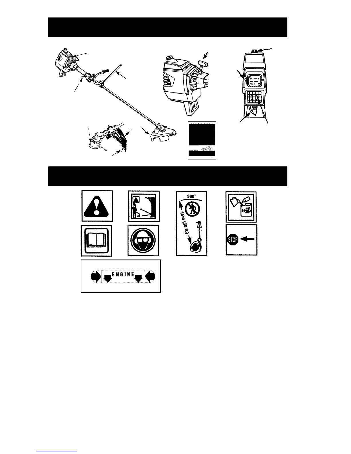
IDENTIFICATION (WHAT IS WHAT?)
Trigger Handle
Handlebar
Shield
Muffler
Choke
Lever
Starter Handle
Spark Plug
Fuel
Cap
ON/STOP
Switch
Operator’s
Manual
Line Limiter Blade
Trimmer
Head
IDENTIFICATION OF SYMBOLS
A.
WARNING!
This brushcutter can be dangerous! Careless or improper use can
cause serious or even fatal injury.
B. Read and understand the instruction manual before using the brushcutter.
C
.
WARNING!
The trimmer line can throw objects violently. You can be blinded or
injured. Always wear eye protection.
D. Always use:
Ear protection
Protective glasses or visor
E. Assist handle to be positioned only between the arrows.
F. The operator of the machine must insure that no one comes within a 15 meter radius
while working. When several operators are working within the same area a safety dis-
tance of at least 15 meters must be observed.
G. Use unleaded or quality leaded petrol and two--stroke oil.
H. Engine ON/STOP Switch.
A.
B.
C.
D.
E.
F.
G.
H.
Page 3

3
SAFETY RULES
WARNING:
When using gardening
appliances, basic safety precautions must always be followed to reduce the risk of fire and
serious injury.
DANGER:
This power tool can be
dangerous!
This unit can cause serious injury
including amputation or blindness to the operator and others. The warnings and safety
instructions in this manual must be followed to
provide reasonable safety and efficiency in
using the unit. The operator is responsible for
following the warnings and instructions in this
manual and on the unit. Read the entire instruction manual before assembling and using the unit! Restrict the use of this unit to persons who read, understand, and follow the
warnings and instructions in this manual and
on the unit. Never allow children to operate
this unit.
SAFETY INFORMATION
ON THE UNIT
INSTRUCTION
MANUAL
DANGER:
Blade can thrust violently
away from material it does not cut. Blade
thrust can cause amputation of arms or legs.
Keep people and animals 15 meters away.
WARNING:
Trimmer line can throw
objects violently. You and others can be
blinded or injured. Wear safety glasses and
leg protection.
Leg Guards
Boots
Eye
Protection
ALWAYS WEAR:
Thrown
Objects
WARNING:
Hazard zone for thrown
objects. Blade/T rimmer line can throw objects
violently. Others can be blinded or injured.
Keep people and animals 15 meters away.
Hazard Zone
15 Meters
WARNING:
Do not use trimmer head
as a fastening device for the blade.
WARNING:
The blade continues to
spin after the throttle is released or, engine is
turned off. The coasting blade can throw objects
or seriously cut if accidentally touched. Stop the
blade by contacting the right hand side of the
coasting blade with material already cut.
Stop coasting
blade by contact
with cut material
OPERATOR SAFETY
S
Dress properly. Always wear safety
glasses or similar eye protection when
operating, or performing maintenance on
your unit. (Safety glasses are available.)
Eye protection should be marked Z87.
Always wear face or dust mask if operation
is dusty.
S
Always wear heavy, long pants, long sleeves,
boots, and gloves. Wearing safety leg guards
is recommended.
S
Always wear foot protection. Do not go
barefoot or wear sandals.
S
Secure hair above shoulder length. Secure or
remove loose clothing and jewelry or clothing
with loosely hanging ties, straps, tassels, etc.
They can be caught in moving parts.
S
Being fully covered also helps protect you
from debris and pieces of toxic plants
thrown by spinning line/blade.
S
Stay alert. Do not operate unit when you are
tired, ill, upset or under influence of alcohol,
Page 4

4
drugs, or medication. Watch what you are
doing; use common sense.
S
Wear hearing protection.
S
Never start or run the engine inside a
closed room or building. Breathing exhaust
fumes can kill.
S
Keep handles free of oil and fuel.
S
Always use the handlebar and a properly
adjusted shoulder strap with a blade (see
ASSEMBLY).
UNIT/MAINTENANCE SAFETY
WARNING:
Stop unit and disconnect
the spark plug before performing maintenance (except carburetor adjustments).
S
Look for and replace damaged or loose
parts before each use. Look for and repair
fuel leaks before use. Keep unit in good
working condition.
S
Throw away blades that are bent, warped,
cracked, broken, or damaged in any other
way. Replace trimmer head parts that are
cracked, chipped, broken, or damaged in
any other way before using the unit.
S
Maintain unit according to recommended
procedures. Keep blade sharp. Keep cutting line at the proper length.
S
Use only recommended replacement line.
Never use wire, rope, string, etc.
S
Install required shield properly before using
the unit. Use the metal shield for all metal
blade use. Use the plastic shield for all line
trimmer use.
S
Use only specified blade or trimmer head;
make sure it is properly installed and securely fastened.
S
Never start engine with clutch drum removed. The clutch can fly off and cause serious injury.
S
Be sure blade or trimmer head stops turning
when engine idles.
S
Make carburetor adjustments with the lower end supported to prevent blade or trimmer line from contacting any object. Hold
unit by hand; do not use the shoulder strap
for support.
S
Keep others away when making carburetor
adjustments.
S
Use only recommended McCullochraccessories and replacement parts.
S
Have all maintenance and service not explained in this manual performed by your authorized service dealer .
FUEL SAFETY
S
Mix and pour fuel outdoors.
S
Keep away from sparks or flames.
S
Use a container approved for fuel.
Do not smoke or allow smoking near fuel or
the unit or while using the unit.
S
Avoid spilling fuel or oil. Wipe up all fuel
spills before starting engine.
S
Move at least 3 meters away from fueling
site before starting engine.
S
Stop engine and allow it to cool before
removing fuel cap.
S
Empty the fuel tank before storing or transporting the unit. Use up fuel left in the carburetor by starting the engine and letting it
run until it stops.
S
Store unit and fuel in area where fuel vapors
cannot reach sparks or open flames from
water heaters, electric motors or switches,
furnaces, etc.
S
Always store gasoline in a container approved for flammable liquids.
CUTTING SAFETY
WARNING:
Inspect the area to be
cut before each use. Remove objects (rocks,
broken glass, nails, wire, string, etc.) which
can be thrown or become entangled in the
blade or trimmer head.
S
Keep others including children, animals,
bystanders, and helpers at least 15 meters
away. Stop engine immediately if you are
approached.
S
Always keep engine on the right--hand side
of your body.
S
Hold the unit firmly with both hands.
S
Keep firm footing and balance. Do not
overreach.
S
Keep blade or trimmer head below waist
level. Do not raise engine above your waist.
S
Keep all parts of your body away from
blade, trimmer head, and muffler when
engine is running. A hot muffler can cause
serious burns.
S
Cut from your left to your right. Cutting on
right side of the shield will throw debris
away from the operator.
S
Use only in daylight or good artificial light.
S
Use only for jobs explained in this manual.
TRANSPORTING AND STORAGE
S
Stop the unit before carrying.
S
Keep muffler away from your body.
S
Allow the engine to cool and secure the unit
before storing or transporting it in a vehicle.
Empty the fuel tank before storing or
transporting the unit. Use up fuel left in the
carburetor by starting the engine and letting
it run until it stops.
S
Store unit so the weed blade or line limiter
blade cannot accidentally cause injury. The
unit can be hung by the tube.
S
Always install transport guard on blade
before transporting or storage.
S
Store unit out of reach of children.
SAFETY NOTICE:
Exposure to vibrations
through prolonged use of gasoline powered
hand tools could cause blood vessel or nerve
damage in the fingers, hands, and joints of
people prone to circulation disorders or abnormal swellings. Prolonged use in cold weather
has been linked to blood vessel damage in
otherwise healthy people. If symptoms occur
such as numbness, pain, loss of strength,
change in skin color or texture, or loss of feeling
in the fingers, hands, or joints, discontinue the
use of this tool and seek medical attention. An
anti--vibration system does not guarantee the
avoidance of these problems. Users who operate power tools on a continual and regular basis
must monitor closely their physical condition
and the condition of this tool.
Page 5
5
ASSEMBLY
CARTON CONTENTS
Check carton contents against the following list:
S
Brushcutter
S
Blade shield screws (4)
S
Cupped washer
S
Large nut for installing blades
S
Hex wrench
S
Metal shield
S
Plastic shield
S
Shoulder strap with warning
S
4--point weed blade
S
Trimmer head
S
Handlebar
S
Wing nut
WARNING:
Always stop unit and disconnect spark plug before performing any assembly procedures.
WARNING:
If received assembled,
repeat all steps to ensure your unit is properly
assembled and all fasteners are secure.
Examine parts for damage. Do not use damaged parts.
It is normal for the fuel filter to rattle in the
empty fuel tank.
Finding fuel or oil residue on muffler is normal
due to carburetor adjustments and testing
done by the manufacturer.
TOOLS REQUIRED
S
Hex wrench (provided)
S
Adjustable wrench
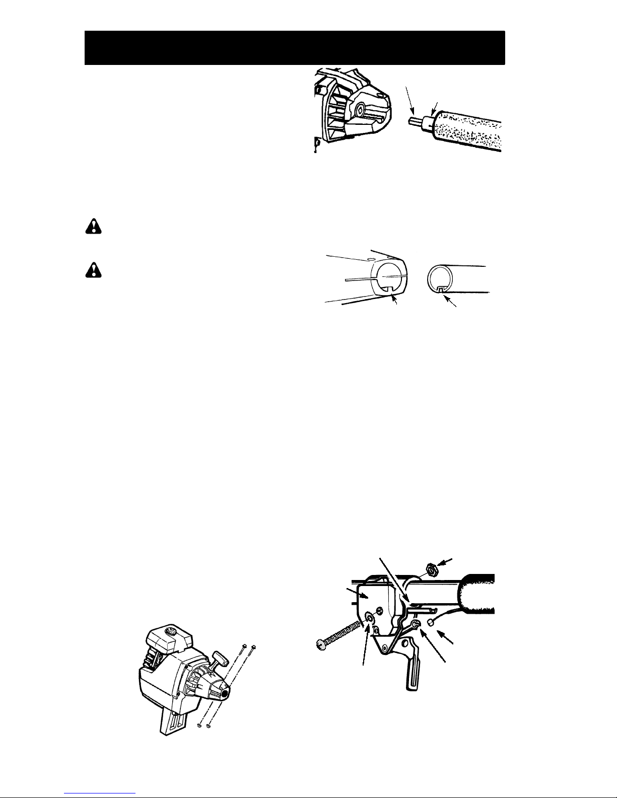
ATTACH THE TUBE
NOTE:
Illustrations within this section will help
in identifying the assembly steps. Be sure to
read each section and review the illustrations,
before you begin.
NOTE:
A drive shaft is located in the center of
the tube. Make sure this shaft does not fall out of
the tube. Dirt on the shaft will significantly reduce the life of the unit. If this shaft falls out,
clean, relubricate , and re-install.
S
Insert the 2 tube assembly screws and nuts
as illustrated. Keep loose at this time, you
will tighten them during a later step.
S
Position locknuts in lower holes.
S
Tighten the screws with the hex wrench just
enough to hold the hardware together while
holding the locknuts with your other hand.
S
Remove the packing cover from the
straight end of the tube (your unit may not
have a packing cover.)
S
Pull about 1/2 inch of the drive shaft out of
the inside of the tube.
Drive shaft
Tube
NOTE:
The end of the drive shaft is square.
This square end fits inside a square hole in a
shaft inside the engine. Look inside the end of
the engine and you will see the square hole in
the shaft.
NOTE:
The end of the tube has a groove that
aligns with a ridge in the engine opening. Locate the groove and ridge.
GrooveRidge
S
Align the groove in the tube with the ridge in
the engine opening. Insert the tube into the
opening.
S
Firmly push the tube into engine until it will no
longer go into the opening.
S
Tighten screws alternately with the hex
wrench until secure.
ATTACH THE THROTTLE CABLE
CAUTION:
Do not bend the throttle cable.
S
Slide the throttle trigger housing from the
foam grip about 1!to 1 --1/2!.
S
Insert the throttle cable through the tunnel in
the foam grip until the end of the cable extends at least 2 inches beyond grip.
S
Hold the trigger away from the tube; insert
the barrel end of the throttle cable into the
round opening in the trigger.
NOTE:
When inserting barrel end of the
throttle cable into the round opening in trigger,
make sure that the barrel is completely inserted and throttle cable is located in the split
in the arm.
Screw
Nut
Arm
Barrel
Round hole in
trigger
Throttle
trigger
housing
Foam grip
Lockwasher
S
Push the cable back into the split in the arm.
Guide the arm into the foam grip tunnel until
the throttle trigger housing is flush against
the grip.
S
Squeeze and hold trigger against foam grip.
Install screw and nut.
Page 6

6
CAUTION:
Do not overtighten screw.
There must be at least 1/8” free play in the trigger. Make sure trigger will move freely so the
engine can fully return to idle when the trigger
is released.
ATTACHING THE HANDLEBAR
DANGER:
During blade usage, the
barrier portion of the handlebar must be
installed as shown to provide a barrier between operator and the spinning blade.
S
Locate the decal on the handlebar. This
decal includes two arrows. Position the
handlebar with the mounting bracket
between these arrows.
S
Position the bracket cover over the
handlebar. Again make sure the handlebar
is between the arrows.
S
Insert screws and hand tighten only. Be
sure the handlebar is installed correctly;
then, tighten each screw securely with the
short hex wrench.
Bracket Cover
Screw
Mounting
Bracket
Handlebar
ASSEMBLY OF SHOULDER STRAP
1. Align shoulder strap clamp between han-
dlebar mounting bracket and engine.
2. Firmly push the shoulder strap clamp
onto the tube. Be sure that the shoulder
strap clamp is installed with the hex
shaped recession (on the clamp) facing
the left side of the tube as viewed from the
engine.
Throttle Grip
Shoulder Strap
Clamp
T--handle
Nut
Handlebar
Mounting Bracket
Screw
3. Drop the threaded end of the screw
through the opening in the top of the T-handle.
4. Pull on the threaded end of the screw to
bring the head of the scrw past the tab inside the T--handle.
Before Assembly
Top View Assembled
Screw
T--handle
Square Head
Screw Seated
Tab
5. Seat nut in the hex shaped recession on
the back side of the shoulder strap clamp.
6. Insert the threaded end of the screw
through the hole in the shoulder strap
clamp and tighten securely by hand
only.
WARNING:
Proper shoulder strap
and handlebar adjustments are required before
starting the engine.
7. Try on shoulder strap and adjust for fit and
balance before starting the engine or beginning a cutting operation.
8. Insert your right arm and head through
the shoulder strap and allow it to rest on
your left shoulder. Make sure the danger
sign is on your back and the hook is to the
right side of your waist.
NOTE:
A one-half twist is built in the shoulder
strap to allow the strap to rest flat on the
shoulder.
9. Adjust the strap, allowing the hook to be
about 150 mm below the waist.
10. Fasten the strap hook to the clamp located
between the trigger handle and the handlebar clamp base and lift the tool to the operating position.
CONFIGURING YOUR UNIT
Y ou can configure your unit using a cutting
head for grass and light weeds, or a weed
blade for cutting grass, weeds, and brush up
to 13 mm in diameter. To assemble your unit,
go to the section for the desired configuration
and follow the instructions.
ASSEMBLY INFORMATION -TRIMMER HEAD
TRIMMER
HEAD
NOTE:
Remove the blade and metal shield
before attaching the plastic shield and trimmer
head. To remove blade, push in locking lever
and hold. Rotate blade nut until the locking lever
falls into one of the grooves in the dust cup.
Continue to hold the locking lever. This will keep
the shaft from turning while loosening the blade
nut. Remove blade nut by turning clockwise.
Release locking lever. Remove both washers
and blade. T o remove metal shield, loosen and
remove the four mounting screws. See ATTACHIN G THE METAL SHIELD and INSTALLA TION OF THE METAL BLADE for illustrations. Be sure to store all parts and instructions
for future use.
Page 7

7
ATTACHING THE PLASTIC SHIELD
AND TRIMMER HEAD
WARNING:
The shield must be properly installed. The shield provides partial
protection from the risk of thrown objects to
the operator and others and is equipped with
a line limiter blade which cuts excess line to
the proper length. The line limiter blade (on
underside of shield) is sharp and can cut you.
1. Remove wing nut from shield.
2. Insert bracket into slot on shield.
3. Pivot shield until bolt passes through hole
in bracket.
4. Tighten the wing nut securely.
NOTE:
If your unit has a plastic cover over
the threads on the threaded shaft, remove the
covering to expose the threads. Before
installing the trimmer head, make sure the
dust cup is positioned on the gearbox as
shown below.
Wing Nut
Retaining Washer
Dust Cup
Bracket
Slot
Shield
Gearbox
NOTE:
Make sure all parts are properly
installed as shown in the illustration before
installing the trimmer head.
5. Push in locking lever and hold.
6. Rotate dust cup until the locking lever
falls into one of the grooves
.
Locking Lever
7. Continue to hold in locking lever. This will
keep the shaft from turning while tightening the trimmer head.
8. Thread trimmer head onto the shaft in the
direction shown on the decal. Tighten until secure.
9. Release locking lever.
ASSEMBLY INFORMATION -- WEED
BLADES
WEED
BLADE
NOTE:
Remove the trimmer head and plastic shield before attaching the metal shield
and installing the weed blade. To remove the
trimmer head, push in locking lever and hold.
Rotate trimmer head until the locking lever
falls into one of the grooves in the dust cup.
Continue to hold in locking lever. This will
keep the shaft from turning while loosening
the cutting head. To remove the plastic shield,
loosen and remove wing nut. Pivot shield to
release bracket from slot. See INSTALLATION OF THE CUTTING HEAD and ATTACHING THE PLASTIC SHIELD for illustrations. Be sure to store all parts and
instructions for future use. Never use the
trimmer head with the metal blade installed.
ATTACHING THE METAL SHIELD
WARNING:
The metal shield must be
properly installed on the tool anytime the tool is
used with a blade. Failure to install the shield in
the position shown can result in serious injury to
the operator. The length of the shield must be
aligned with the length of the tube.
1. Place the metal shield under the gearbox,
and align the screw holes.
Shield
Gearbox
2. Insert and thread the 4 mounting screws
through the holes of the gearbox and the
metal shield. Tighten evenly and securely with the hex wrench provided.
Page 8

8
INSTALLATION OF THE METAL
BLADE
WARNING:
Wear protective gloves
when handling or performing maintenance on
the blade to avoid injury. The blade is sharp and
can cut you even when it is not moving.
WARNING:
Do not use any blades, or
fastening hardware other than the washers and
nuts shown in the following illustrations. These
parts must be provided by McCulloch, and
installed as shown below. Failure to use proper
parts can cause the blade to fly off and seriously
hurt you or others.
NOTE:
The dust cup and retaining washer are
located on the gearbox shaft and not in the parts
bag. All other fasteners mentioned in the following assembly steps are in the parts bag.
1. Remove the retaining washer from the
threaded shaft of the gearbox. Leave the
dust cup on the shaft.
2. Install the blade and the retaining washer
over the threaded shaft.
3. Make sure the raised part of the retaining
washer is facing the gearbox and the
raised area fits into the hole in the center
of the blade.
4. Slide the blade and retaining washer onto
the shaft of the gearbox.
5. Place the cupped washer onto the shaft.
Make sure the cupped side of the washer
is toward the blade.
6. Install the blade nut by threading onto the
shaft counterclockwise.
Shield
Blade
Retaining
Washer
Dust Cup
Cupped
Washer
Nut
Threaded Shaft
Gearbox
NOTE:
Make sure all parts are in place as illustrated, and the blade is sandwiched between
the dust cup and the retaining washer. There
should be no space between the blade and the
dust cup or the retaining washer .
7. Push in locking lever and hold.
8. Rotate blade nut until the locking lever falls
into one of the grooves in the dust cup.
Locking Lever
9. Continue to hold in locking lever. This will
keep the shaft from turning while tightening
the blade nut.
10. Tighten blade nut firmly with a wrench.
11. Release locking lever.
12. Turn blade by hand. If the blade binds
against the shield, or appears to be uneven,
the blade is not centered, and you must reinstall.
Page 9

9
OPERATION
BEFORE STARTING ENGINE
WARNING:
Be sure to read the fuel
information in the safety rules before you begin. If you do not understand the safety rules,
do not attempt to fuel your unit. Contact an authorized service dealer.
FUELING ENGINE
WARNING:
Remove fuel cap slowly
when refueling.
This engine is certified to operate on un-
leaded gasoline. Before operation, gasoline
must be mixed with a good quality 2-cycle aircooled engine oil. Mix gasoline and oil at a ratio of 40:1 (2.5%). A 40:1 ratio is obtained by
mixing 5 liters of unleaded petrol with 0,125 liter of oil. DO NOT USE automotive oil or boat
oil. These oils will cause engine damage.
When mixing fuel, follow instructions printed
on container. Once oil is added to gasoline,
shake container momentarily to assure that
the fuel is thoroughly mixed. Always read and
follow the safety rules relating to fuel before
fueling your unit.
IMPORTANT
Experience indicates that alcohol blended
fuels (called gasohol or using ethanol or
methanol) can attract moisture which leads to
separation and formation of acids during storage. Acidic gas can damage the fuel system
of an engine while in storage.
To avoid engine problems, empty the fuel system before storage for 30 days or longer.
Drain the gas tank, start the engine and let it
run until the fuel lines and carburetor are
empty. Use fresh fuel next season.
Never use engine or carburetor cleaner products in the fuel tank or permanent damage
may occur.
HOW TO STOP YOUR UNIT
S
To stop the engine, move the ON/STOP
switch to the STOP position.
S
If engine does not stop, move choke lever
to FULL CHOKE position.
HOW TO START YOUR UNIT
WARNING:
The trimmer head will
turn while starting the engine.
Avoid any contact with the muffler. A hot muffler can cause serious burns.
STARTING A COLD ENGINE (or a
warm engine after running out of
fuel)
Starting Position
Choke lever
Starter
Handle
Muffler
1. Set unit on a flat surface.
2. Move the ON/STOP switch to the ON
position.
3. Move choke lever to the FULL CHOKE
position.
4. Squeeze the throttle trigger fully and hold
through
all remaining steps.
5. Pull starter rope handle sharply until engine sounds as if it is trying to start, but do
not pull rope more than 6 times.
6. As soon as engine sounds as if it is trying
to start, move choke lever to HALF
CHOKE.
7. Pull starter rope sharply until engine runs,
but no more than 6 pulls. If the engine
doesn’t start after 6 pulls (at the HALF
CHOKE position), move the choke lever
to the FULL CHOKE position. Squeeze
and hold the throttle trigger and pull the
starter rope 2 more times. Move the
choke lever to the HALF CHOKE position
and pull the starter rope until the engine
runs, but no more than 6 pulls.
NOTE:
If engine still doesn’t start, it is
probably flooded. Proceed to STARTING
A FLOODED ENGINE.
8. Once the engine starts, allow it to run 10
seconds, then move the choke lever to
OFF CHOKE. Allow the unit to run for 30
more seconds at OFF CHOKE before releasing the throttle trigger.
NOTE:
If engine dies with the choke lever
in the OFF CHOKE position, move the
choke lever to the HALF CHOKE position
and pull the rope until engine runs, but no
more than 6 pulls.
STARTING A WARM ENGINE
1. Move the ON/STOP switch to the ON
position.
2. Move the choke lever to the HALF
CHOKE position.
3. Squeeze and hold the throttle trigger.
Keep throttle trigger fully squeezed until
the engine runs smoothly.
4. Pull starter rope sharply until engine runs,
but no more than 5 pulls.
5. Allow engine to run 15 seconds, then
move the choke lever to the OFF CHOKE
position.
NOTE:
If engine has not started, pull starter rope 5 more pulls. If engine still does not
run, it is probably flooded.
Page 10

10
STARTING A FLOODED ENGINE
Flooded engines can be started by placing
the choke lever in the OFF CHOKE position;
then, pull the rope to clear the engine of excess fuel. This could require pulling the starter
handle many times depending on how badly
the unit is flooded.
If the unit still doesn’t start, refer to the
TROUBLESHOOTING TABLE.
OPERATING POSITION
ALWAYS WEAR:
Long Pants
Boots
Eye Protection
Cut from your left to your right.
When operating unit, clip shoulder strap onto
clamp, stand as shown and check for the following:
S
Wear eye protection and heavy clothing.
S
Extend your left arm and hold handlebar
grip with your left hand.
S
Hold throttle grip with your right hand with
finger on throttle trigger.
S
Keep unit below waist level.
S
Keep shoulder strap pad centered on your
left shoulder and danger sign centered on
your back.
S
Maintain full weight of tool on your left
shoulder.
S
Without bending over, keep the blade or
trimmer head near and parallel to the
ground and not crowded into material being
cut.
OPERATING INSTRUCTIONS FOR
USE WITH TRIMMER HEAD
WARNING:
Always wear eye protection. Never lean over the trimmer head. Rocks
or debris can ricochet or be thrown into eyes
and face and cause blindness or other serious
injury.
Before trimming, bring engine to a speed
sufficient to cut material to be trimmed.
Do not run the engine at a higher speed than
necessary . The cutting line will cut efficiently
when the engine is run at less than full
throttle. At lower speeds, there is less engine
noise and vibration. The cutting line will last
longer and will be less likely to “weld” onto the
spool.
Always release the throttle trigger and allow
the engine to return to idle speed when not
cutting.
To stop engine:
S
Release the throttle trigger.
S
Push and release the engine ON/STOP
switch.
TRIMMER LINE ADVANCE
The trimmer line will advance approximately
50 mm each time the bottom of the trimmer
head is tapped on the ground with the engine
running at full throttle.
The most efficient line length is the maximum
length allowed by the line limiter.
Always keep the shield in place when the tool
is being operated.
To advance line:
S
Operate the engine at full throttle.
S
Hold the trimmer head parallel to and above
the grassy area.
S
Tap the bottom of the trimmer head lightly
on the ground one time. Approximately 50
mm of line will be advanced with each tap.
Always tap the trimmer head on a grassy
area. Tapping on surfaces such as concrete
or asphalt can cause excessive wear to the
trimmer head.
If the line is worn down to 50 mm or less, more
than one tap will be required to obtain the
most efficient line length.
CUTTING METHODS
WARNING:
Use minimum speed
and do not crowd the line when cutting around
hard objects (rock, gravel, fence posts, etc.),
which can damage the trimmer head, become
entangled in the line, or be thrown causing a
serious hazard.
S
The tip of the line does the cutting. You will
achieve the best performance and minimum line wear by not crowding the line into
the cutting area. The right and wrong ways
are shown below.
S
The line will easily remove grass and
weeds from around walls, fences, trees and
flower beds, but it also can cut the tender
bark of trees or shrubs and scar fences.
S
For trimming or scalping, use less than full
throttle to increase line life and decrease
head wear, especially:
S
During light duty cutting.
S
Near objects around which the line can
wrap such as small posts, trees or fence
wire.
S
For mowing or sweeping, use full throttle for
a good clean job.
TRIMMING -- Hold the bottom of the trimmer head about 80 mm above the ground
and at an angle. Allow only the tip of the line
to make contact. Do not force trimmer line
into work area.
Page 11

11
Trimming
80 mm above
ground
SCALPING -- The scalping technique removes unwanted vegetation down to the
ground. Hold the bottom of the trimmer head
about 80 mm above the ground and at an angle. Allow the tip of the line to strike the
ground around trees, posts, monuments, etc.
This technique increases line wear.
MOWING -- Your trimmer is ideal for mowing in places conventional lawn mowers
cannot reach. In the mowing position, keep
the line parallel to the ground. Avoid pressing the head into the ground as this can
scalp the ground and damage the tool.
SWEEPING -- The fanning action of the rotating line can be used to blow away loose debris from an area. Keep the line parallel to and
above the area surface and swing the tool
from side to side.
OPERATING INSTRUCTIONS FOR
USE WITH WEED BLADE
S
Blade Thrust is a reaction that only occurs
when using a bladed unit. This reaction can
cause serious injury such as amputation.
Carefully study this section. It is important that
you understand what causes blade thrust,
how you can reduce the chance of its
occurring, and how you can remain in control
of unit if blade thrust occurs.
S
WHAT CAUSES BLADE THRUST -- Blade
Thrust can occur when the spinning blade
contacts an object that it does not cut. This
contact causes the blade to stop for an instant
and then suddenly move or “thrust” away
from the object that was hit. The “thrusting”
reaction can be violent enough to cause the
operator to be propelled in any direction and
lose control of the unit. The uncontrolled unit
can cause serious injury if the blade contacts
the operator or others.
S
WHEN BLADE THRUST OCCURS -Blade Thrust can occur without warning if
the blade snags, stalls, or binds. This is
more likely to occur in areas where it is
difficult to see the material being cut. By
using the unit properly, the occurrence of
blade thrust will be reduced and the
operator will be less likely to lose control.
S
Cut only grass, weeds, and woody brush up
to 13 mm in diameter with the weed blade.
Do not let the blade contact material it
cannot cut such as stumps, rocks, fences,
metal, etc., or clusters of hard, woody brush
having a diameter greater than 13 mm.
S
Keep the blade sharp. A dull blade is more
likely to snag and thrust.
S
Cut only at full throttle. The blade will have
maximum cutting power and is less likely to
bind or stall.
S
“Feed” the blade deliberately and not too
rapidly. The blade can thrust away if it is fed
too rapidly.
S
Cut only from your left to your right. Cutting
on right side of the shield will throw debris
away from the operator.
S
Use the shoulder strap and keep a firm grip
on the unit with both hands. A properly
adjusted shoulder strap will support the
weight of the unit, freeing your arms and
hands to control and guide the cutting
motion.
S
Keep feet comfortably spread apart and
braced for a possible sudden, rapid thrust of
unit. Do not overreach. Keep firm footing and
balance.
S
Keep blade below waist level; it will be
easier to maintain control of unit.
S
Do not raise the engine above your waist as
the blade can come dangerously close to
your body.
Page 12

12
S
Do not swing unit with such force that you
are in danger of losing your balance.
Bring the engine to cutting speed before entering the material to be cut.If the blade does
not turn when you squeeze the throttle trigger,
make sure tube is fully inserted into the engine.
Always release the throttle trigger and allow
engine to return to idle speed when not cutting. The blade should not turn while the engine is running at idle. If the blade turns at idle,
do not use your unit. Refer to the CARBURETOR ADJUSTMENT section or contact your
authorized service dealer.
S
Maintain good firm footing while using the
unit. Do this by planting feet firmly in a
comfortable apart position.
S
Cut while swinging the upper part of your
body from left to right.
S
As you move forward to the next area to cut,
be sure to maintain your balance and
footing.
Cut using the 2
o’clock to 4 o’clock
position of the
blade
2 o’clock
4 o’clock
RECOMMENDED CUTTING POSITION
WARNING:
The operator or others
must not try to clear away cut material with the
engine running or the blade turning to avoid
serious injury. Stop engine and blade before
removing materials wrapped around blade or
tube.
MAINTENANCE
WARNING:
Disconnect the spark
plug before performing maintenance except
for carburetor adjustments.
CHECK FOR LOOSE
FASTENERS AND PARTS
S
Spark Plug Boot
S
Air Filter
S
Housing Screws
S
Assist Handle Screw
S
Debris Shield
CHECK FOR DAMAGED OR
WORN PARTS
Contact an authorized service dealer for replacement of damaged or worn parts.
S
ON/STOP Switch -- Ensure ON/STOP
switch functions properly by pushing and
releasing the switch. Make sure engine
stops. Wait 5 seconds before attempting to
restart unit to allow switch to reset. Restart
engine and continue
S
Fuel Tank -- Discontinue use of unit if fuel
tank shows signs of damage or leaks.
S
Debris Shield -- Discontinue use of unit if
debris shield is damaged.
INSPECT AND CLEAN UNIT AND DECALS
S
After each use, inspect complete unit for
loose or damaged parts. Clean the unit and
decals using a damp cloth with a mild detergent.
S
Wipe off unit with a clean dry cloth.
CLEAN AIR FILTER
A dirty air filter decreases engine performance and increases fuel consumption and
harmful emissions. Always clean after every
5 hours of operation.
1. Clean the cover and the area around it to
keep dirt from falling into the carburetor
chamber when the cover is removed.
2. Remove parts as illustrated.
NOTE:
To avoid creating a fire hazard or
producing harmful evaporative emissions, do
not clean filter in gasoline or other flammable
solvent.
3. Wash the filter in soap and water.
4. Allow filter to dry.
5. Add a few drops of oil to the filter;
squeeze the filter to distribute oil.
6. Replace parts.
Air Filter
Cover
Screws
Air Filter
Back
view of
Air Filter
Cover
REPLACE SPARK PLUG
Replace the spark plug each year to ensure
the engine starts easier and runs better. Set
spark plug gap at 0,6 mm. Ignition timing is
fixed and nonadjustable.
1. Twist, then pull off spark plug boot.
2. Remove spark plug from cylinder and
discard.
3. Replace with Champion RCJ-8Y spark
plug and tighten securely with a 19 mm
socket wrench.
4. Reinstall the spark plug boot.
Page 13

13
SERVICE AND ADJUSTMENTS
LINE REPLACEMENT
WARNING:
Trimmer head parts that
are chipped, cracked, broken, or damaged in
any other way can fly apart and cause serious
injury. Do not use. Replace damaged parts
before using unit.
S
Press the tab on the side of the trimmer
head and twist the lock ring.
S
Remove the lock ring and tap button.
Tab
Lock Rin
g
Tap Button
Trimmer
Head
S
Pull spool out of the trimmer head.
S
Clean dirt and debris from all parts.
S
Replace with a pre-wound spool , or replace line using 40 feet of 0.080!(2 mm)
diameter line.
S
When installing new line on an existing spool,
insert 1/16!of the line into the anchoring hole
in the bed of the spool, and wrap the line
evenly and and firmly around the spool in the
direction of the arrow found on the spool.
Anchoring
Hole
S
Insert the end of the line through the exit hole
in the side of the trimmer head.
NOTE:
A metal insert is located in the exit
hole. As your unit wears from use, you can reinstall this insert upside down to provide a
new surface for the exit of the line from the
trimmer head.
WARNING:
When installing the metal
insert, you must install from the inside of the
trimmer head. If installed on the outside of the
trimmer head, this insert can fly off and become
a dangerous missile.
Metal Insert
S
Once line is passed through the exit hole,
place spool in the trimm er head. Press the
spool down and turn the spool until it locks
down and does not pop up when you release
the spool.
S
Make sure the line is not caught between
the rim of the spool and the wall of the trimmer head.
S
Replace the tap button, and place the lock
ring onto the trimmer head.
S
Align the lock ring over the catches on the
trimmer head. Push the ring down and turn
until catches lock into place.
Catch
Catch
Catch
Catch
Lock
Tab
S
Make sure the lock ring is securely fastened by pulling on it and twisting in both directions.
WARNING:
All catches must be fastened and lock tab latched in the lock ring. If
installed incorrectly, lock ring can fly off and become a dangerous missile.
S
Pull the line extending from the trimmer
head. This will allow the spool to release
from the locked position.
SPOOL REPLACEMENT
S
Replace the spool when the square corners
on the lugs are rounded off, reduced in size,
or broken. Follow instructions under LINE
REPLACEM ENT for removing and installing
the spool.
Worn
Lug
Normal lug
BLADE REPLACEMENT
Refer to the ASSEMBLY section for blade replacement instructions and illustrations.
CARBURETOR ADJUSTMENT
Y our carburetor is equipped with limiter caps.
Damage will occur if you turn the needles beyond the limiter stops. Carburetor adjustment
is a complicated task. We recommend that
you take your unit to an authorized service
dealer.
Page 14

14
STORAGE
WARNING:
Perform the following
steps after each use:
S
Allow engine to cool before storing or transporting.
S
Store unit and fuel in a well ventilated area
where fuel vapors cannot reach sparks or
open flames from water heaters, electric
motors or switches, furnaces, etc.
S
Store unit with all guards in place. Position
unit so that any sharp object cannot accidentally cause injury.
S
Store unit and fuel well out of the reach of
children.
SEASONAL STORAGE
Prepare unit for storage at end of season or if
it will not be used for 30 days or more.
S
If your unit is to be stored for a period of
time, clean the entire unit before lengthy
storage.
ENGINE
S
Remove spark plug and pour 1 teaspoon of
40:1, 2-cycle engine oil (air cooled) through
the spark plug opening. Slowly pull the
starter rope 8 to 10 times to distribute oil.
S
Replace spark plug with new one of recommended type and heat range.
S
Clean air filter.
S
Check entire unit for loose screws, nuts,
and bolts. Replace any damaged, broken,
or worn parts.
S
At the beginning of the next season, use
only fresh fuel having the proper gasoline to
oil ratio.
OTHER
S
Do not store gasoline from one season to
another.
S
Replace your gasoline can if it starts to rust.
TROUBLE CAUSE REMEDY
Engine will not
start.
1. Engine flooded.
2. Fuel tank empty.
3. Spark plug not firing.
4. Fuel not reaching
carburetor.
5. Carburetor requires
adjustment.
1. See “Starting a Flooded Engine” in
Operation Section.
2. Fill tank with correct fuel mixture.
3. Install new spark plug.
4. Check for dirty fuel filter; replace.
Check for kinked or split fuel line;
repair or replace.
5. See “Carburetor Adjustment” in
Service and Adjustments Section.
Engine will
not idle
properly.
1. Carburetor requires
adjustment.
2. Crankshaft seals worn.
3. Compression low.
1. See “Carburetor Adjustment” in
Service and Adjustments Section.
2. Contact an authorized service dealer.
3. Contact an authorized service dealer.
1. Air filter dirty.
2. Spark plug fouled.
3. Carburetor requires
adjustment.
4. Carbon build-up on
muffler outlet screen.
5. Compression low.
Engine will not
accelerate,
lacks power,
or dies under
a load.
1. Clean or replace air filter.
2. Clean or replace plug
and regap.
3. See “Carburetor Adjustment” in
Service and Adjustments Section.
4. Contact an authorized service dealer.
5. Contact an authorized service dealer.
Engine
smokes
excessively.
1. Choke partially on.
2. Fuel mixture incorrect.
3. Air filter dirty.
4. Carburetor requires
adjustment.
1. Adjust choke.
2. Empty fuel tank and refill with
correct fuel mixture.
3. Clean or replace air filter.
4. See “Carburetor Adjustment” in
Service and Adjustments Section.
Engine runs
hot.
1. Fuel mixture incorrect.
2. Spark plug incorrect.
3. Carburetor requires
adjustment.
4. Carbon build-up on
muffler outlet screen.
1. See “Fueling Engine” in Operation
section.
2. Replace with correct spark plug.
3. See “Carburetor Adjustment” in
Service and Adjustments Section.
4. Contact an authorized service dealer.
WARNING:
Always stop unit and disconnect spark plug before performing all of the
recommended remedies below except remedies that require operation of the unit.
TROUBLESHOOTING TABLE
Page 15

15
SAFETY
Page 16

16
SAFETY
Jonsered
SE--561 82 Huskvarna
Huskvarna, Sweden
 Loading...