

Page 1
RODUCT BULLETIN
P
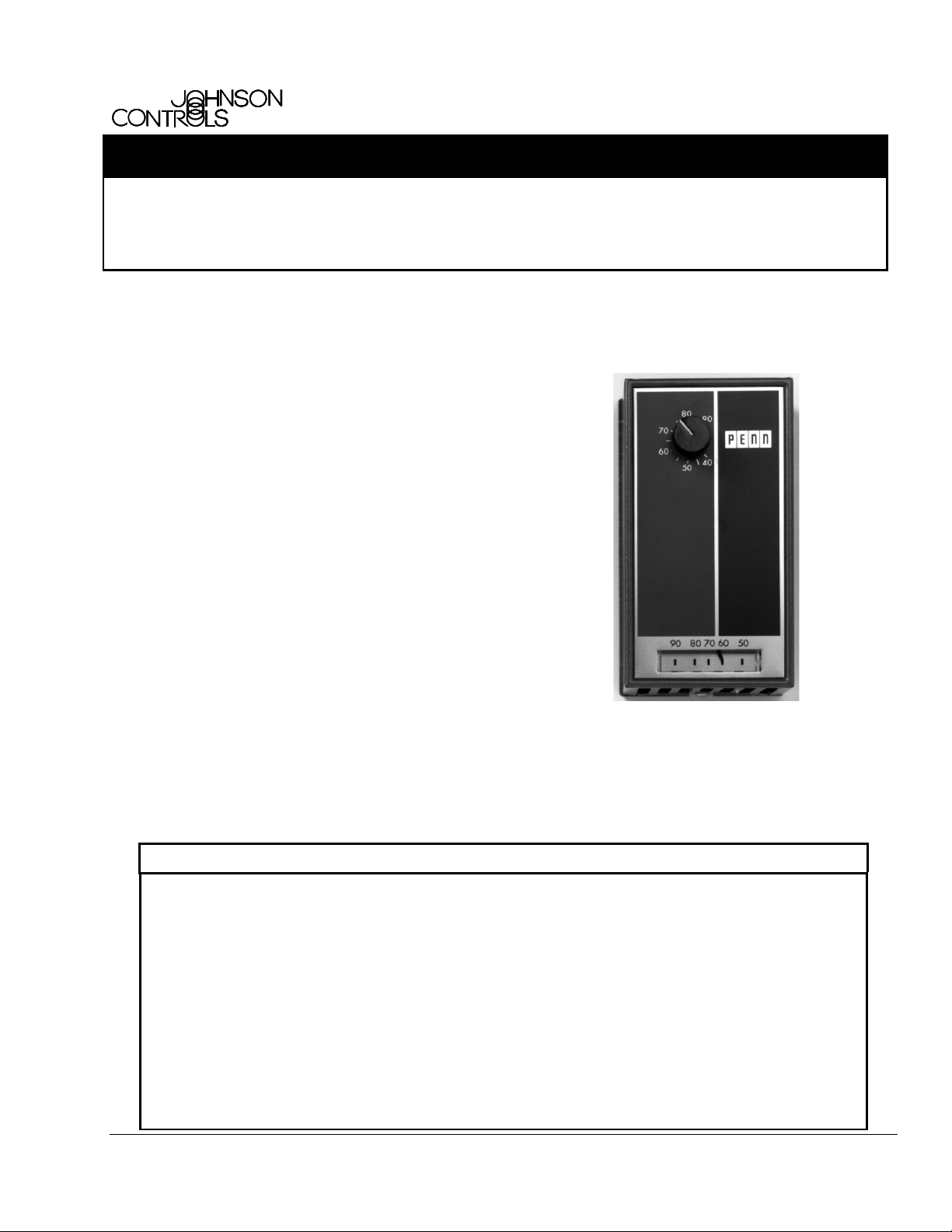
T25 Two-Stage Room Thermostat
T25 thermostats are for line- or low-voltage service
requiring accurate control of of the following operating
functions:
• control of two stages of heating, such as two-rate
unit heaters or duct furnaces, commercial heat
pumps, and other units.
•
control of two stages of cooling, such as two-stage
compressors, dual compressor units, and other
units.
• automatic changeover control of heating and
cooling on three- and four-pipe fan coil
installations and similar applications; automatic
changeover from heating to cooling for unit
operation.
Product/Technical T25
Issue Date 01/25/02
Typical uses are for valves, relays, fan coils,
compressor controls, and other applications where low
differentials and accurate sensing are required. Two
Single-Pole, Double-Throw (SPDT) switches permit
independent control circuits.
Each switch may be wired to make or break the control
circuit on a rise in temperature. A removable jumper
across the “common” terminals is supplied as
standard.
Features and Benefits
Dependable, Field-proven
❑
Pennswitches
Sensitive, Liquid-charged
❑
Temperature Element with an
Efficient Lever Mechanism
Standard Bimetal Thermometer Requires no calibration
❑
Semi-concealed, Field-settable
❑
High-end Temperature Stop
Provides accurate measurement and long-term stability
Achieves maximum sensitivity to ambient air
temperature changes without using anticipators; no
leveling required
Deters unauthorized temperature settings above a
pre-determined maximum
Figure 1: T25 Two-Stage Room Thermostat
Automatic Changeover Eliminates the need for manual change between cooling
❑
and heating
© 2002 Johnson Controls, Inc.
Code No. LIT-125640 www.johnsoncontrols.com
1
Page 2
Product Overview
T25 thermostats are provided with a dependable,
easy-reading, bimetal, pointer-type thermometer.
The liquid-charged sensing element provides
maximum sensitivity to surrounding air temperature
changes. Coupled with a highly efficient diaphragm
and lever mechanism, the element actuates the
enclosed Pennswitches. This provides a low
operating differential and dependable switching
action without the necessity of either heating or
cooling anticipators.
Eliminating anticipators makes every thermostat a
stock control. Thermostats may be used at voltages
up to 277 VAC, for single-stage or two-stage heating
and/or cooling with a wide range of current loads.
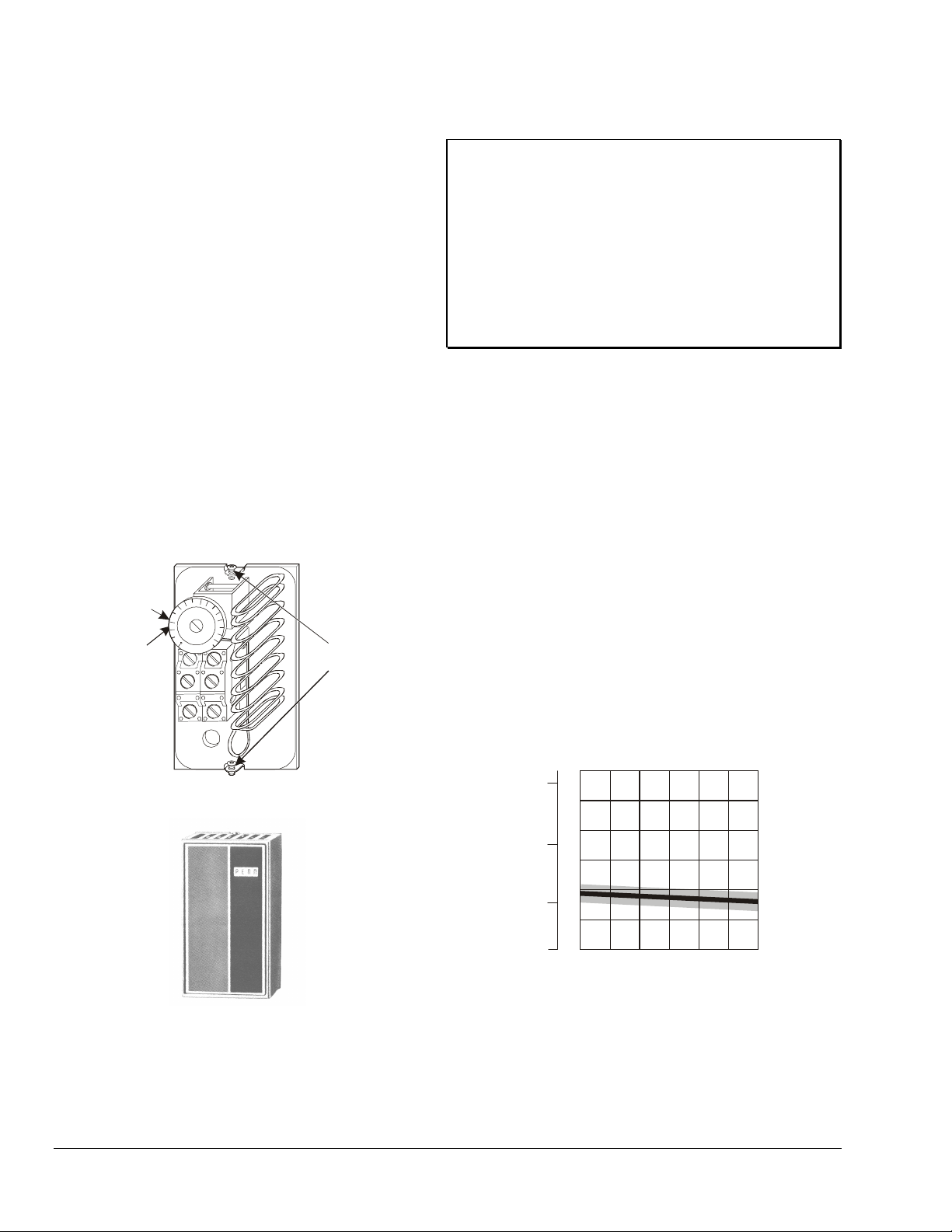
T25 Thermostats are available with concealed
adjustments. (See Figure 3.) All thermostats have
Allen-head cover screws to discourage unauthorized
tampering. The concealed high-temperature stop
allows adjustments in 2F° (1.1C°) increments from
68 to 80°F (20 to 27°C). This feature deters
unauthorized temperature settings above a
pre-determined maximum. (See Figure 2.)
Set Point
Knob
High
Temperature
Stop
0
2
1
5
5
2
1
0
0
3
5
C
Figure 2: Interior of T25
Mounting
Plate
Studs
IMPORTANT: The T25 Series Thermostats are
intended to control equipment under normal operating
conditions. Where failure or malfunction of the
T25 Thermostats could lead to an abnormal operating
condition that could cause personal injury or damage
to the equipment or other property, other devices (limit
or safety controls) or systems (alarm or supervisory
systems) intended to warn of, or protect against,
failure or malfunction of the T25 Thermostats must be
incorporated into and maintained as part of the control
system.
Operating Temperature Differential
The operating temperature differential of any room
thermostat depends on:
• current flow through the thermostat (amperage load)
• air velocity over the thermostat
• rate of temperature change to which the thermostat
is subjected
• whether the thermostat is operating heating or
cooling equipment
Graphs (Figure 4 and Figure 5) show the operating
temperature differentials of these thermostats under
various electrical load conditions.
The air velocity was 25 feet per minute, (.1 m/sec) and
the rate of temperature change was 6F° (3.3C°) per
hour. Higher air velocity and/or a lower rate of
temperature change result in a lower operating
differential.
C° F°
6
3
l
5
a
i
t
n
e
4
r
e
f
f
2
i
D
3
g
n
i
t
a
2
r
e
1
p
O
1
Figure 3: T25 With Concealed Adjustment
2 T25 Two-Stage Room Thermostat Product Bulletin
0246
Amperage Load (units in amperes)
Figure 4: T25 Heating operating differential
Page 3

C° F°
3
l
a
i
t
n
e
r
e
f
f
2
i
D
g
n
i
t
a
r
e
1
p
O
6
Thermostat Guards
Plastic, wire or cast aluminum guards are available at
5
4
3
extra cost. See the GRD Series Universal Thermostat
Guards Plastic, Cast Aluminum or Wire Product Bulletin
(LIT-125740).
Brand Nameplates
2
1
Brand nameplates are available on quantity orders.
Check with Customer Service.
0246
Amperage Load (units in amperes)
Ordering Information
Contact the nearest Johnson Controls representative to
order a T25 Thermostat, and specify the desired product
Figure 5: T25 Cooling Operating Differential
Optional Features
Celsius Dial and Thermometer
Celsius Dial and Thermometer are supplied, when
code number from Table 1.
Repairs and Replacement
Do not attempt field repairs. To replace the thermostat,
knob, faceplate, or cover, contact the nearest
Johnson Controls representative.
specified, at no extra charge. Thermostat range is
40 to 90°F (5 to 30°C). Thermometer scale is 50 to
90°F (10 to 30°C).
Table 1: Selection Chart
Product Code Number Description
T25A-1C Line-voltage Thermostat with Two-Stage and Knob Adjustment
T25A-16C Line-voltage Thermostat with Two-Stage and Concealed Knob Adjustment
T25A-26C Line-voltage Thermostat with Two-Stage and 5°C to 30°C scale Concealed Knob
Adjustment
Table 2: Electrical Ratings
Motor Ratings 120 V 208 V 240 V 277 V
AC Full Load Amperes 6.0 3.5 3.0 -
AC Locked Rotor Amperes 36.0 21.0 18.0 -
Non-Inductive Amperes 10.0 9.2 8.0 7.2
Pilot Duty—125 VA 24 to 277 VAC
Note: When used as a two-circuit switch, the total connected load must not exceed 2,000 VA.
T25 Two-Stage Room Thermostat Product Bulletin 3
Page 4

Technical Data
Product T25 Two-stage Room Thermostat
Output Single-Pole, Double-Throw (SPDT)
Switches Two Enclosed Pennswitches
Cover Cold Rolled Steel with “Tawny Silver” Finish
Each Stage 0.7F° (0.4C°) ApproximatelyDifferential (Mechanical)
Between Stages 3F° (1.7C°) Non-Adjustable
Supply Voltage 120 V, 208 V, 240 V, 277 V
Mounting With Adaptor Plate for Wall or Electrical Box Mounting; Vertical
Mounting Only
Thermostat 40°F to 90°F (5°C to 30°C)Range
Thermometer 50°F to 90°F (10°C to 30°C)
Sensing Element Liquid Charged, No Leveling Required
Individual Pack 1.5 lbs (0.7 kg)Shipping Weight
Overpack of
20 Units
Terminals
Thermometer Bimetal
Agency Listings UL Listed; File E6688, CCN XAPX (U.S.), CCN XAPX7 (Canada)
32 lbs (14.5 kg)
Screw Type. Color Code:
Red is Common.
Red Closes to Yellow on Temperature Rise.
Red Closes to Blue on Temperature Drop.
CSA Certified; File LR948, Class 4813 02
The performance specifications are nominal and conform to acceptable industry standards. For application at conditions beyond these
specifications, consult the local Johnson Controls office. Johnson Controls, Inc. shall not be liable for damages resulting from misapplication or
misuse of its products.
Controls Group
507 E. Michigan Street
P.O. Box 423 Printed in U.S.A.
Milwaukee, WI 53201 www.johnsoncontrols.com
4 T25 Two-Stage Room Thermostat Product Bulletin
 Loading...