

Page 1
Installation Instructions
Issue Date April 9, 2003
AS-CVTPROx00-1 Zone Bus/N2 Bus Interface Converter
Application
The AS-CVTPROx00-1 Zone Bus/N2 Interface
Converter is portable converter designed to provide a
communication interface between the room sensors
and controllers operating on a Zone Bus or N2 Bus
and a Personal Computer (PC) or specified models of
the Palm
TM
family of Personal Digital Assistants
(PDAs). See Table 2 for compatible Palm devices. See
Table 4 for compatible tools, Operating Systems (OSs)
and controllers.
Note: The AS-CVTPROx00-1 converter can be used
in place of the MM-CVT101-0 converter module. The
MM-CVT101-0 converter is not compatible with
Windows NT®, Windows® 2000 and later versions of
Windows OSs.
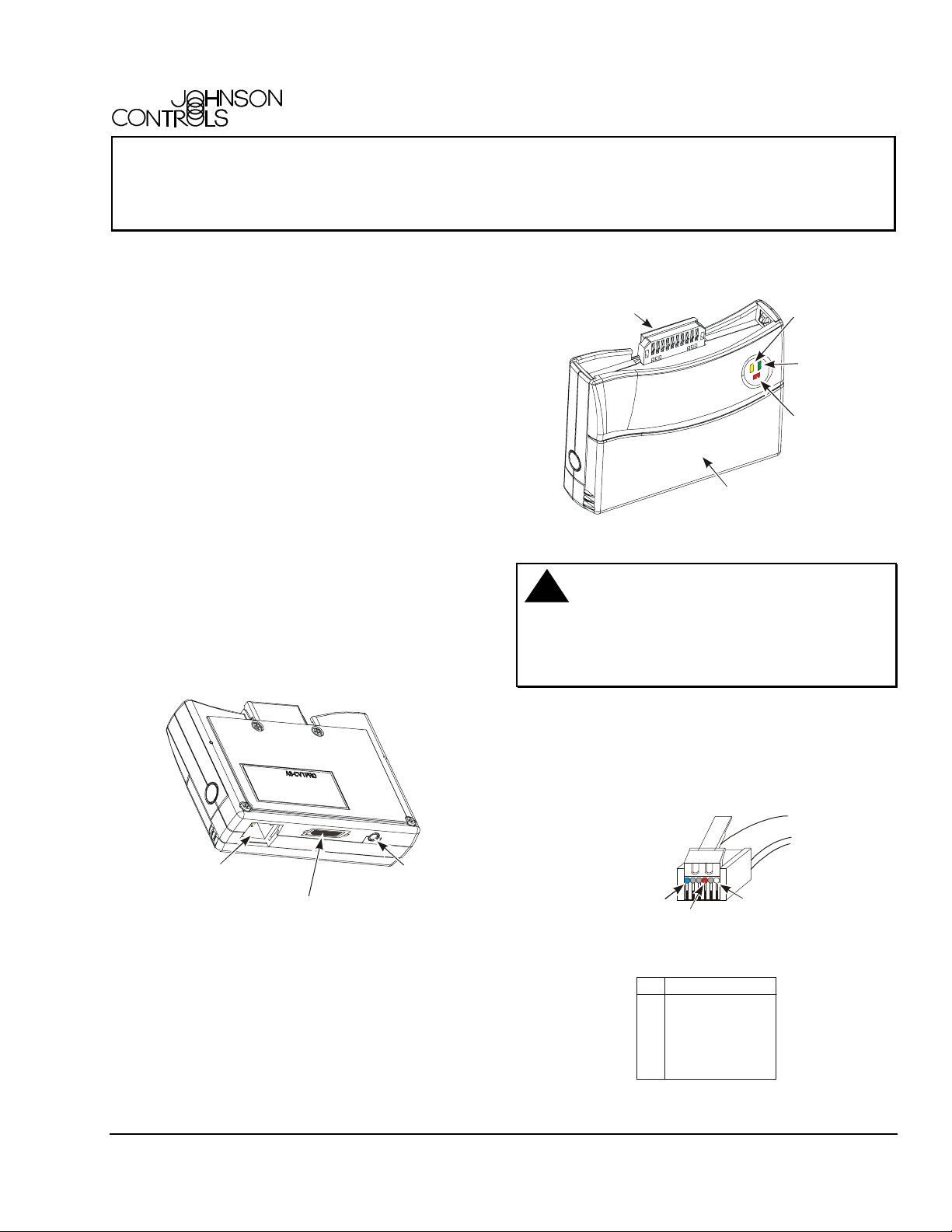
Connector for Palm V Adapter,
Palm III, or Palm VII
Battery Cover
Figure 2: CVTPRO Converter Front
Yell o w L E D
(Receiving)
Green LED
(Transmitting)
Red LED
(Power)
Connection Ports
The back of the CVTPRO converter (Figure 1) has
ports for connections to a Personal Computer (PC), a
Palm handheld PDA, an External Power Adapter, and
a Zone Bus/N2 Bus RJ11 6-pin network cable phone
plug.
6-Pin RJ11 Phone Jack
for Zone Bus/N2 Bus
Network Connection
Serial Port for PC or
Palm m1xx or m5xx Devices
Figure 1: CVTPRO Converter Back
The front of the CVTPRO converter (Figure 2) shows
the mating connector for a Palm III, Palm V, or
Palm VII PDA. Green and yellow Light-Emitting Diodes
(LEDs) display the N2 communication status of the
unit relative to the field device. The red LED shows
power status.
Input Jack for
External Power
Adapter
!
CAUTION: Risk of Property Damage
Do not apply power to the system before checking
all wiring connections. Short circuited or improperly
connected wires may result in permanent damage to
the equipment.
Cable Connectors
Figure 3 shows the 6-pin phone plug end of the
N2 cable used by the CVTPRO converter for N2 Bus
communication. For Zone Bus communication, always
use standard Zone Bus cables.
N2+ (Blue)
N2 Ref. (Red)
Figure 3: N2 Cable 6-Pin RJ11 Network Phone Plug
Pin Signal
1 N2+
2 Zone Bus Power
3 GND
4 N2 Ref
5 Zone Bus Signal
6 N2-
N2- (White)
Figure 4: Zone Bus/N2 Bus RJ11 Network
Phone-Jack Pin Designations
© 2003 Johnson Controls, Inc.
Part No. 24-9544-0, Rev. C www.johnsoncontrols.com
1
Page 2

Table 1: Cables Included with the CVTPRO Converter
To Connect the CVTPRO
Use This Cable:
Converter To:
PC via RS232
Controller via the Zone Bus
Controller via the N2 Bus
Controller Zone Bus (via TE-6x00/
TMZ sensor)
CVTPRO serial cable (18 inches/457 mm)
8-pin RJ45 to 6-pin RJ11 phone cable (6 ft/1.8 m)
4-pin N2 socket/3-pin N2 plug to 6-pin RJ11 phone cable (6 ft/1.8 m)
Note: Remove the 4-pin N2 socket from the cable and use the bare wires to
connect to N2 screw terminal devices.
6-pin to 6-pin RJ11 phone cable (6 ft/1.8 m)
Table 2: Connections to Palm Devices
To Connect the CVTPRO
Use: In This Sequence
Converter To:
Palm III and Palm VII Devices
Palm V Device
Palm m100 and m105 Devices
Palm m125, m130, and m5xx
Devices
1 The Dock V Pro adapter is available from Solvepoint Corporation at www.palmdock.com and local retailers.
2 Order through Johnson Controls e-Purchasing (ITAS). See Table 3.
3 Included with the CVTPRO converter.
Nothing
Dock V Pro™ Adapter
Palm HotSync® Cable
Null Modem Adapter
CVTPRO Serial Cable
Belkin® Serial Sync Cable
Null Modem Adapter
CVTPRO Serial Cable
1
2
2
3
2
3
Palm III/Palm VII ⇒ CVTPRO converter
Palm V ⇒ Dock V Pro Adapter ⇒ CVTPRO converter
Palm m100/m105 ⇒ Palm HotSync Cable ⇒ null
modem adapter ⇒ CVTPRO Serial Cable ⇒
CVTPRO converter
2
Palm m125/m130/m5xx ⇒ Belkin Serial Sync Cable
⇒ null modem adapter ⇒ CVTPRO Serial Cable ⇒
CVTPRO converter
Table 3: CVTPRO Converter and Accessories Product Code Numbers
Product Code
Description
Number
AS-CVTPRO100-1
AS-CVTPRO200-1
AS-CVTPRO-701
AS-CVTCBL-700
Dock V Pro adapter**
F3X1082-03*
ME213*
P10701U*
* These are the manufacturer’s code numbers, not Johnson Controls code numbers. Order through Johnson Controls
e-Purchasing (ITAS).
** The Dock V Pro adapter is available from Solvepoint Corporation at www.palmdock.com and local retailers.
Zone Bus/N2 Bus Interface Converter with 120VAC/3VDC power adapter (North American
version)
Zone Bus/N2 Bus Interface Converter without power adapter (European version)
CVTPRO converter without cables or case
Replacement set of cables used with the CVTPRO converter
Adapter to connect the CVTPRO converter to a Palm V device
Belkin Serial Sync Cable for use with CVTPRO converter and Palm m125/m130/m5xx Devices
Black Box™ Null Modem Adapter for use with CVTPRO and Palm
m100/m105/m125/m130/m5xx Devices
Palm HotSync Cable for use with CVTPRO converter and Palm m100/m105 Devices
2 AS-CVTPROx00-1 Zone Bus/N2 Bus Interface Converter Installation Instructions
Page 3

Connecting to the CVTPRO Converter
Figure 5 illustrates the potential connections
between a CVTPRO converter and other devices.
Refer to Table 1 and Table 2 for more information on
cables and Palm devices. See Figure 6 and Figure 7
for more detail about N2 Bus connections.
External Power
Adapter
Personal Computer
or
A
S
P
N
P
O
C
I
L
A
I
R
L
O
C
T
A
U
L
T
C
A
5
4
b
a
3
F
c
M
d
2
e
1
I
D
N
U
E
N
Palm m1xx or m5xx
(with additional connectors)
See Table 2.
3
DB9 Port
1
DB9
Connector
CVTPRO
Serial Cable
5
4
3
2
1
C
A
R
L
O
C
T
A
U
L
F
I
D
N
Palm III,
or
A
S
P
N
P
O
I
L
I
T
C
A
b
a
c
M
d
e
U
E
N
CVTPRO
Converter
Serial Port
RJ11 6-pin Jack
for Zone Bus/N2 Bus
Connection
Palm V device with Dock V PRO Adapter,
Palm VII
1, 2
TE-6x00/TMZ
Room Sensor
Compatible
Controller
or
or
Zone Bus
RJ45 Jack,
8 Pin
N2 Bus
N2 Bus Interface,
4-Pin N2 Socket/
3-Pin N2 Plug with Tab
RJ11 Jack,
6-Pin
Notes:
1. Do not connect the CVTPRO converter to the Palm device and laptop/PC at the same time.
2. Unpl ug the Palm device from the CVTPRO converter when not in use (conserves battery power).
3. The CVTPRO200- (European version) does not ship with an external power adapter.1
Figure 5: Overview of Possible CVTPRO Converter Connections
3 AS-CVTPROx00-1 Zone Bus/N2 Bus Interface Converter Installation Instructions
Page 4

Connecting the CVTPRO Converter to a Controller
with N2 Screw Terminals
To connect the CVTPRO converter to a controller with
screw terminals (Figure 6):
1. Disconnect the three N2 wires from the controller
screw terminals and temporarily isolate the
individual bare wires with insulating tape.
2. Remove the 4-pin N2 socket from the CVTPRO
N2 cable to expose the three wires (Figure 6 and
Figure 7).
3. Connect the exposed N2+ (blue), N2- (white), and
Ref (red) wires from the CVTPRO N2 cable to the
controller screw terminals. Observe proper
polarity.
4. Connect the 6-pin RJ11 phone plug on the
opposite end of the CVTPRO N2 cable to the
CVTPRO converter (Figure 3 and Figure 5).
CVTPRO N2 Cable
3-Pin N2 Plug
To scan a N2 Bus:
1 Disconnect the N2 Bus from the N2 master
controller.
2 Remove the N2 plug (with attached N2 wires) from
the controller (4-pin plug on the VMA and 3-pin
plug on other controllers).
3 Connect the 3-pin or 4-pin N2 plug that was
disconnected from the controller in Step 2, to the
4-pin N2 socket on the CVTPRO converter cable.
(See Figure 7.) Observe proper polarity (N2+ is
blue, N2- is white, Ref is red).
4 Connect the 6-pin RJ11 phone plug on the
opposite end of the CVTPRO N2 cable to the
CVTPRO converter (Figure 3 and Figure 5).
Cable t o the
6-Pin RJ11 Phone Plug
and CVTPRO Converter
Ref (Red)
N2- (White)
N2+ (Blue)
Wire Directly to
Controller Terminals
cvtunt.cdr
Remove
4-Pin N2
Socket
Figure 6: CVTPRO N2 Connection to Controllers
with Screw Terminals
Connecting the CVTPRO Converter to a Controller with a N2 Jack
To connect the CVTPRO converter to a controller with
a removable N2 plug:
1. Remove the 3 or 4-pin N2 plug from the controller.
2. Plug the 3-pin plug CVTPRO N2 cable into the
jack on the controller (The Variable Air Volume
Modular Assembly [VMA] has 4-pin jack, and other
N2 controllers have 3-pin jacks). Observe proper
polarity (N2+ is blue, N2- is white, Ref is red).
3. Connect the 6-pin RJ11 phone plug on the
opposite end of the CVTPRO N2 cable to the
CVTPRO converter (Figure 3).
Note: Figure 7 shows the possible connections with
a VMA controller with a removable 4-pin N2 plug.
VMA
4-Pin Jack
CVTPRO N2 Cable
3-Pin N2 Plug
Cable t o the
6-Pin RJ11 Phone Plug
and CVTPRO Converter
4-Pin N2 Socket on the
CVTPRO N2 Cable
4-Pin N2 Plug
Unplugged
from the VMA
To
N2 REF
Next
N2
Device
N2-
N2+
SH
REF N2- N2+
LD
S
R
N
H
E
2
L
-
F
D
N
2
+
N2+
N2-
N2 REF
Connect these
components
to communicate
with the controller
via the CVTPRO
Convert er.
Connect these
components
to scan the N2 Bus
via the CVTPRO
Convert er.
To
Next
N2
Device
CVTVMA
Figure 7: CVTPRO N2 Connection to a VMA with a
Removable N2 Plug
4 AS-CVTPROx00-1 Zone Bus/N2 Bus Interface Converter Installation Instructions
Page 5

Compatibility
Table 4 lists compatible tools, Operating Systems, and
controllers used over the Zone Bus and N2 Bus with
the CVTPRO converter.
Compatible controllers include the Air Handling Unit
(AHU), Unitary Controller (UNT), Variable Air Volume
Controller (VAV), Network Dialer Module (NDM),
and VMA.
Table 4: Compatibility Chart
Tool Bus Operating System Compatible Controller
HVAC PRO Software (part of
M-Tool Release 5.0 or later)
VBT1400
VBT1200
GX-9100 Software
Configuration Tool (part of
M-Tool Release 5.0 or later)
XTM Configuration Tool
NDM Configuration Tool
Note: The CVTPRO converter is not compatible with Zone Terminal Units (ZTUs). For ZTUs, use the CBLPRO-2
converter. See the Auxiliary Gear Technical Bulletin (LIT-6363080) for details on Johnson Controls® converters.
1 For proper CVTPRO converter operation when running on Windows NT OSs, Service Pack 6 must be installed.
2 For proper CVTPRO converter operation when running on Windows 2000 OSs, use the Professional Edition only, and
Service Pack 2 must be installed.
3 On Zone Bus applications running on Windows 2000 OSs, HVAC PRO Version 8.04B or later must also be installed.
* When using the VMA14x0 with HVAC PRO software (versions prior to Version 8.04B only) over the Zone Bus with
Windows NT OSs, a Device Conflict box appears whenever the user attempts an operation (for example, upload or
download). To bypass the box, select Yes or No and the box disappears. The selected operation continues as
expected.
N2 Bus Windows 98 SE/Windows NT1/
Windows 2000PE
Zone Bus Windows 98 SE/Windows 2000PE
OS
Zone Bus Windows NT
Zone Bus Palm Personal Digital Assistant (PDA)
with OS Version 3.5 or later
Zone Bus Palm PDA with OS Version 2.x or later VMA12x0
N2 Bus Windows 98 SE/Windows NT
Windows 2000PE
N2 Bus Windows 98 SE/
Windows 2000PE
N2 Bus Windows 98 SE/
Windows 2000PE
2
OS
1
2
OS
1
Windows NT1/
2
OS
Windows NT1/
2
OS
2, 3
1
/
AHU1xx
UNT1xx
UNT11xx
VAV1xx
VMA14x0
VMA14x0*
VMA14x0
DT-9100
DX-9100
XT9100 (XP91xx)
XTM-905 (XPx-xxx)
XTM-105 (XPx-xxx)
NDM
Battery Power Recommendations
The CVTPRO converter requires two (user-supplied)
AAA alkaline type batteries on N2 Bus applications
(when the External Power Adapter is not used).
Battery life varies depending on the N2 Bus load,
ambient temperature and type of batteries. See
Table 5 and observe the following guidelines.
• Always have a spare set of new batteries on hand.
• When performing long downloads with the
CVTPRO converter, use the External Power
Adapter instead of batteries.
AS-CVTPROx00-1 Zone Bus/N2 Bus Interface Converter Installation Instructions 5
Table 5: *Typical Battery Life in CVTPRO Converter
AAA Battery:
Manufacturer
Battery Life
and Model/Type
Ray-O-Vac® Industrial Plus 4-1/2 hours
Duracell® CopperTop 5-1/2 hours
Eveready® Energizer Max® 6-1/2 hours
* using a CVTPRO converter in continuous operation
on a fully loaded N2 Bus at room temperature (70°F
[21°C])
Page 6

Technical Specifications
Product
Power Requirements Zone Bus: Controller Supplied Power: Stand-alone or via Thermostat - 24 VAC or
Agency Listings
Ambient Operating
Conditions
Ambient Storage
Conditions
Shipping Weight
The performance specifications are nominal and conform to acceptable industry standards. For application at conditions beyond these
specifications, consult the local Johnson Controls office. Johnson Controls, Inc. shall not be liable for damages resulting from misapplication or
misuse of its products.
Refer to the Auxiliary Gear Technical Bulletin (LIT-6363080) for necessary information on ordering, operation, and performance specifications
of this product.
AS-CVTPROx00-1 Zone Bus/N2 Bus Interface Converter
AS-CVTPRO100-1 with 120VAC/3VDC External Power Adapter (North American version)
AS-CVTPRO200-1 without power adapter (European version)
VMA applications - 15 VDC
N2 Bus: External Power Adapter: 120 VAC to +3 VDC 200 mA Class 2 Transformer
(Included with CVTPRO Converter in North America only) or
Battery Power: Two type AAA Alkaline, not included, see Table 5.
FCC Part 15 Subpart B, Class A
CE Mark: EN50081-2 (Electromagnetic Compatibility, EN55011, Class A)
EN50082-2 (Electromagnetic Compatibility, EN61000-3-2 and EN61000-3-3)
0 to 50°C (32 to 122°F) 20-80% RH (Relative Humidity)
30°C (86°F) Maximum Dew Point
-40 to +60°C (-40 to 140°F) 5-95% RH
30°C (86°F) Maximum Dew Point
0.227 kg (0.5 lb.)
Controls Group
507 E. Michigan Street
P.O. Box 423 Published in U.S.A.
Milwaukee, WI 53201 www.johnsoncontrols.com
6 AS-CVTPROx00-1 Zone Bus/N2 Bus Interface Converter Installation Instructions
 Loading...