

Johnson Controls AHV60D, AHV48D, AHV42D, AHV36C, AHV30B Technical Manual Installation Maintenance
...Page 1
SINGLE PIECE ECM
AIR HANDLERS
FOR USE WITH SPLIT-SYSTEM
AIR CONDITIONERS & HEAT PUMPS
MODELS: AHV18 THRU 60
Due to continuous product improvement,
specifications are subject to change without notice.
Visit us on the web at:
www.upgnet.com
Additional rating information can be found at:
www.ahridirectory.org
WARRANTY
Standard 5-year limited parts warranty.
Extended 10-year limited pa rt s warranty when product is
registered online within 90 days of purchase for replacement or closing for new home construction.
ISO 9001
Certified Quality
Management System
TECHNICAL
GUIDE
TECHNICAL
GUIDE
824756-BTG-C-0912
DESCRIPTION
The AHV Air Handler line offers the ultimate in comfort, sound
and application flexibility. The air handler is shipped ready to be
installed in upflow, horizontal left or right position, with minor
adjustments. No special kits are required to install this deluxe
product.
Air handlers are shipped with “Flex-coils” without a factory
installed metering device. Flex coil models allow these coils to
be used with R-22 or R-410A for added flexibility to meet refrigerant choices. An orifice metering device or a R-410A TXV
should be installed in the field to meet your system requirements.
FEATURES
Thermostatic Expansion Valve - Provides the ultimate refrigerant control required for today’s high efficient product. The
UPG bolt-on TXV provides easy installation to convert the air
handler to the required refrigerant, which is a true bolt-on
design that does not require brazing to replace or install.
Rust-proof Plastic Drain Pans - The vertical and horizontal
drain pans in these units are made of a fiberglass reinforced
thermoset polymer that will not rust or compromise stability at
high temperatures.
Insulated Cabinet - All air handler cabinets are thermally insulated with 3/4” foil faced insulation to prevent sweating.
Factory Sealed - Achieves 2% or less total airflow leakage rate
at duct leakage test conditions for system airflow verification.
Durable Finish Inside and Out - Air handler casings are made
of pre-painted galvanized steel which provides a better paint to
steel bond that resists corrosion and rust creep. All internal coil
sheet metal parts are made of G60 galvanized or prepainted
G30 galvanized steel.
Filters - All models have internal filter racks provided for use
with 1” thick standard size filters.
Electric Heat Kits - The 6HK series of field installed electric
heat kits are available for installation friendly and easy service
applications. These 6HK kits have heat capacities from 2 kW to
25 kW to meet the application requirements.
ECM Variable Sp eed Motor - Designed for efficient, quiet operation with added indoor comfort control. With the use of a
humidistat, the system will monitor the humidity in the home
and automatically keep the desired humidity level in both winter
and summer seasons. The ECM motor utilizes only 24% of the
energy used by standard blower motors to reduce your overall
heating and cooling costs.
The climate comfort system allows dealer to customize comfort
settings based on regional location.
Communications - These models may be connected as part of
a communications system using a 4-wire connection bus.
FOR DISTRIBUTION USE ONLY - NOT TO BE USED AT POINT OF RETAIL SALE
Page 2
824756-BTG-C-0912
J
D
Blower
Compartment
Circuit Breaker
Panel
Drain Pan Connections
for Horizontal Applications
Refrigerant
Connections
Drain Connections
for Upflow
Applications
7-11/32”
B
A
K
C
1-1/2”
Top Outlet
Dimensions
Filter
Access
18-9/32”
E
Bottom Inlet
Dimensions
13”
F
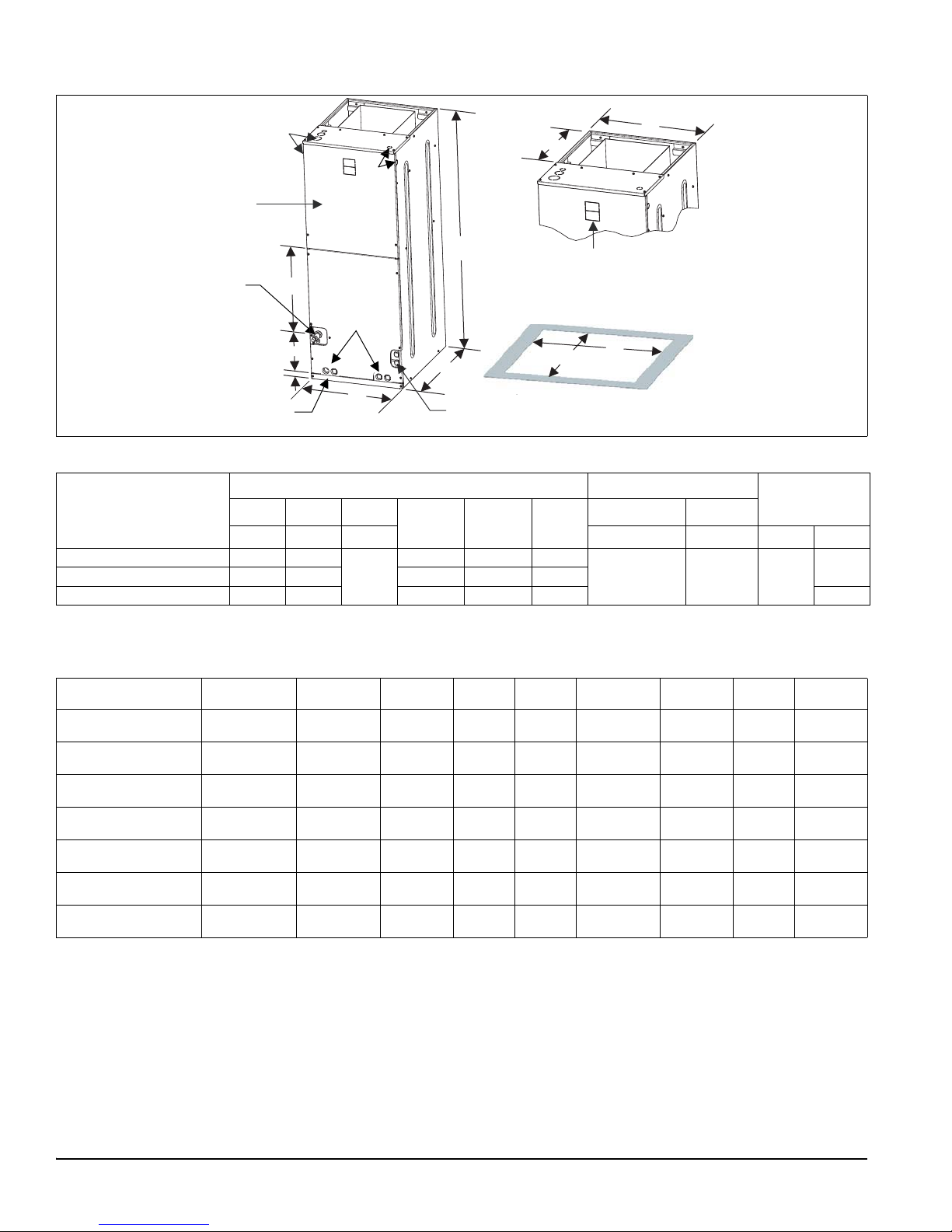
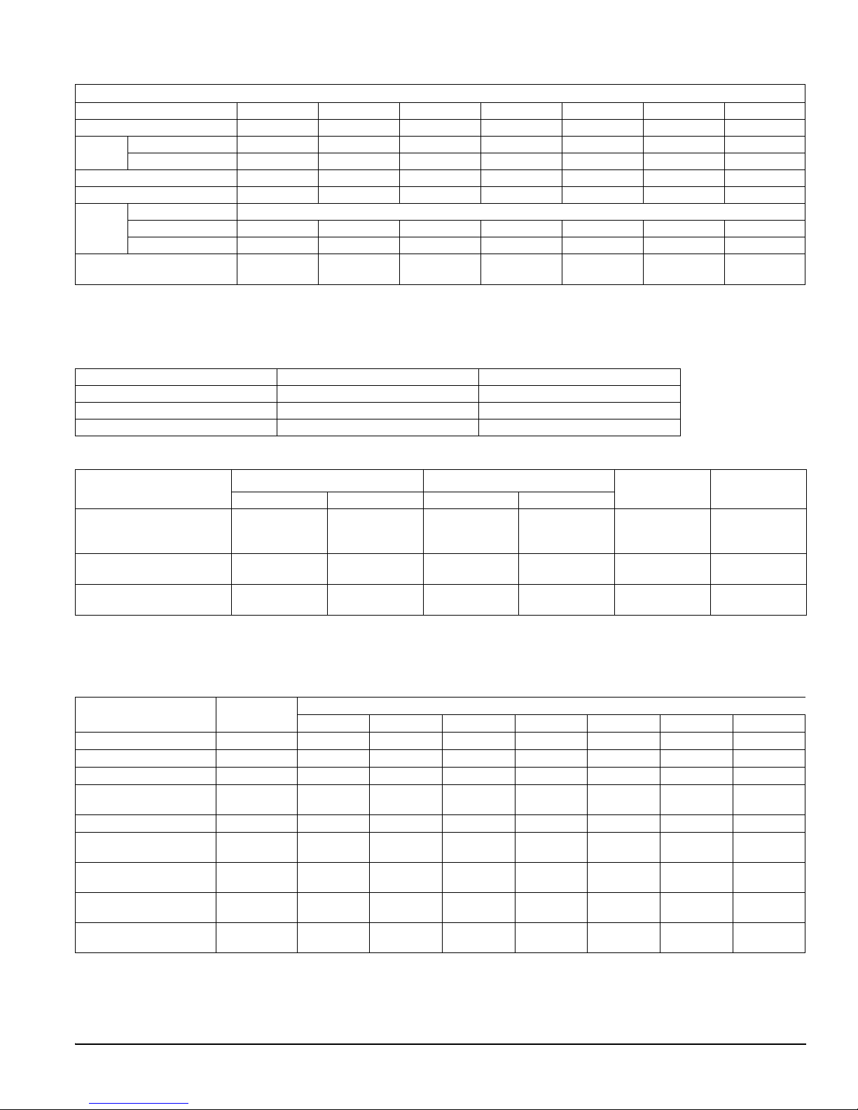
DIMENSIONS & DUCT CONNECTION DIMENSIONS
Dimensions
Models
1
Dimensions
ABC
DEF
Wiring Knockouts
2
JK
Refrigerant
Connections
Line Size
Height Width Depth Power Control Liquid Vapor
AHV18B/AHV24B/AHV30B 46 17 1/2
AHV36C 52 21 21 1/2 17-13/32 20
21 1/2
AHV42D/AHV48D/AHV60D 57 24 1/2 26 20-29/32 23-1/2 7/8
1. All dimensions are in inches.
2. Actual size (conduit size).
16 1/2 13-29/32 16 1/2
7/8 (1/2)
1-3/8(1)
1-23/32 (1-1/4)
7/8 (1/2) 3/8
COIL TECHNICAL DATA
Models Application
AHV18B3XH21
AHV24B3XH21
AHV30B3XH21
AHV36C3XH21
AHV42D3XH21
AHV48D3XH21
AHV60D3XH21
Cooling /Heat
Cooling /Heat
Cooling /Heat
Cooling /Heat
Cooling /Heat
Cooling /Heat
Cooling /Heat
Pump
Pump
Pump
Pump
Pump
Pump
Pump
Refrig.
Conn. Types
Sweat 3.4 2 14 (2) 14 x 17.5 1 x 0.866 3/8 Enhanced
Sweat 3.9 3 12 (2) 16 x 17.5 1 x 0.866 3/8 Enhanced
Sweat 3.9 3 12 (2) 16 x 17.5 1 x 0.866 3/8 Enhanced
Sweat 4.9 3 12 (2) 20 x 17.5 1 x 0.866 3/8 Enhanced
Sweat 5.4 3 12 (2) 22 x 17.5 1 x 0.866 3/8 Enhanced
Sweat 5.8 3 11 (2) 24 x 17.5 1 x 0.866 3/8 Enhanced
Sweat 6.8 3 12 (2) 28 x 17.5 1 x 0.866 3/8 Enhanced
Face Area
(Sq. Ft.)
Rows
Deep
Fins
Per In.
Coil Size
Tube
Geometry
Tube
Dia.
Fin
Type
3/4
2 Johnson Controls Unitary Products
Page 3
824756-BTG-C-0912
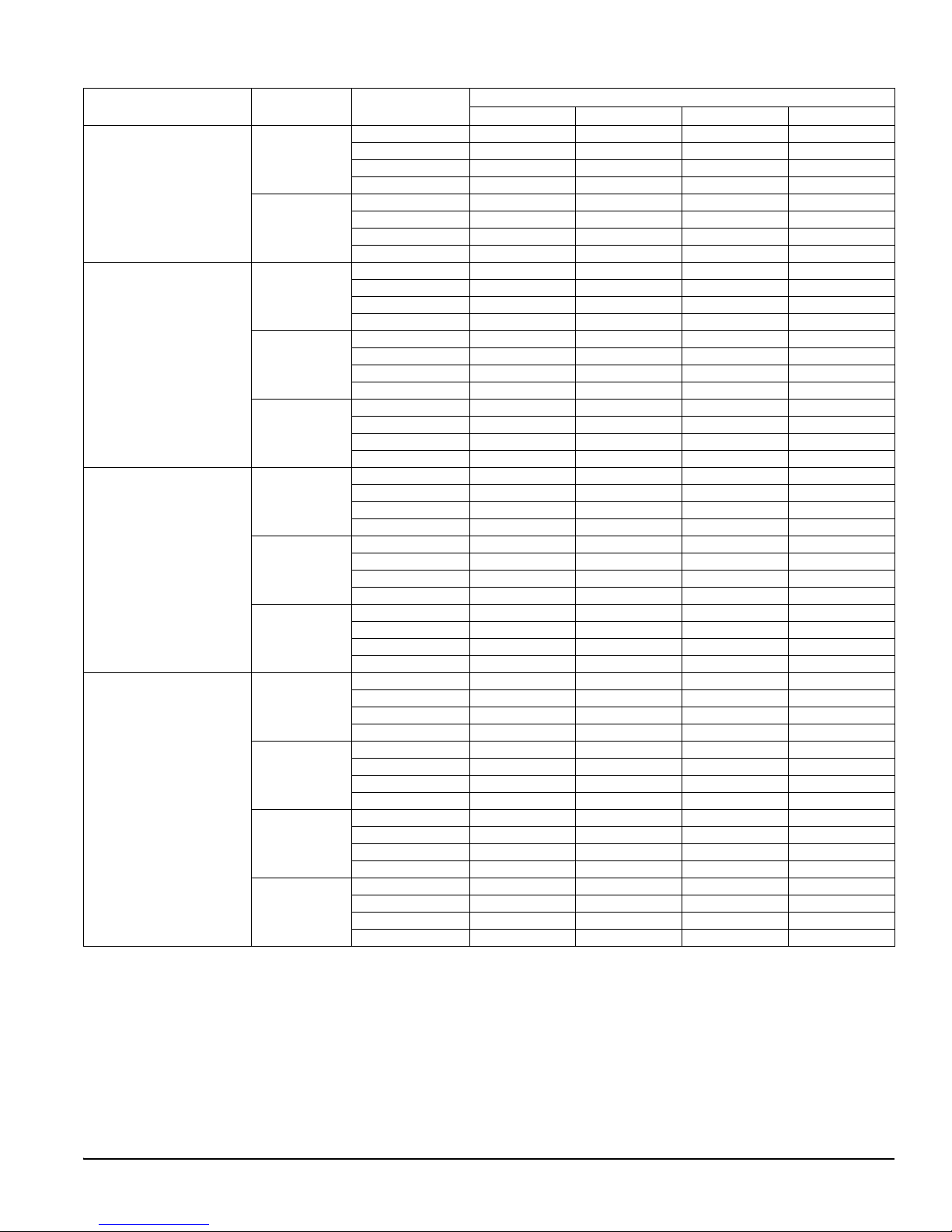
COOLING CAPACITY
Models
AHV18B
AHV24B
AHV30B
AHV36C
For notes see Page 4.
1
Rated CFM
610
850
585
795
985
585
795
985
730
855
1000
1190
Entering Air
2
Dry/Wet Bulb (°F)
MBH@ Evap. Temp. and Corresponding R-410A Pressure (°F/PSIG)
35/107.9 40/118.9 45/130.7 50/143.3
85/72 37.9 33.7 28.3 23.3
80/67 31.8 27 22.5 17.6
75/62 26.4 21.5 16.7 11.6
70/57 20.7 18.4 15.8 13.5
85/72 49.7 43.2 36.9 28.4
80/67 42.1 35.1 28.8 22.5
75/62 33.7 28 21.4 14.7
70/57 26.5 23.8 20.3 16.9
85/72 38.7 34.4 30.1 24.7
80/67 33.6 28.9 23.9 18.9
75/62 27.2 22.7 17.8 12.8
70/57 21.2 18.6 16.2 13.7
85/72 50.8 45.2 38.4 32.0
80/67 43.7 36.8 31 24.0
75/62 35.7 29.5 23.1 16.1
70/57 27.9 24.5 21 17.6
85/72 64.9 54 45.6 37.8
80/67 52.3 44.6 36.9 28.4
75/62 42.2 35.2 26.8 19.3
70/57 33.6 29.6 25.4 21.4
85/72 49.3 45.2 38.3 31.4
80/67 43 37.3 31 24.0
75/62 34.7 28.8 22.8 16.2
70/57 26.8 23.4 20.4 16.9
85/72 59.1 51 44.1 36.5
80/67 49.3 42.4 35.4 27.6
75/62 39.9 33.1 26.1 18.2
70/57 31.1 26.9 23.5 19.7
85/72 65.2 59.5 51.2 41.3
80/67 56.4 48.3 39.9 31.3
75/62 45.8 38.1 29.7 20.8
70/57 35.7 31.2 26.9 22.6
85/72 67.5 65.9 59.8 48.7
80/67 64.9 56.7 46.2 35.7
75/62 53.5 43.2 34.1 24.0
70/57 41.4 36.6 31.5 26.2
Johnson Controls Unitary Products 3
Page 4
824756-BTG-C-0912
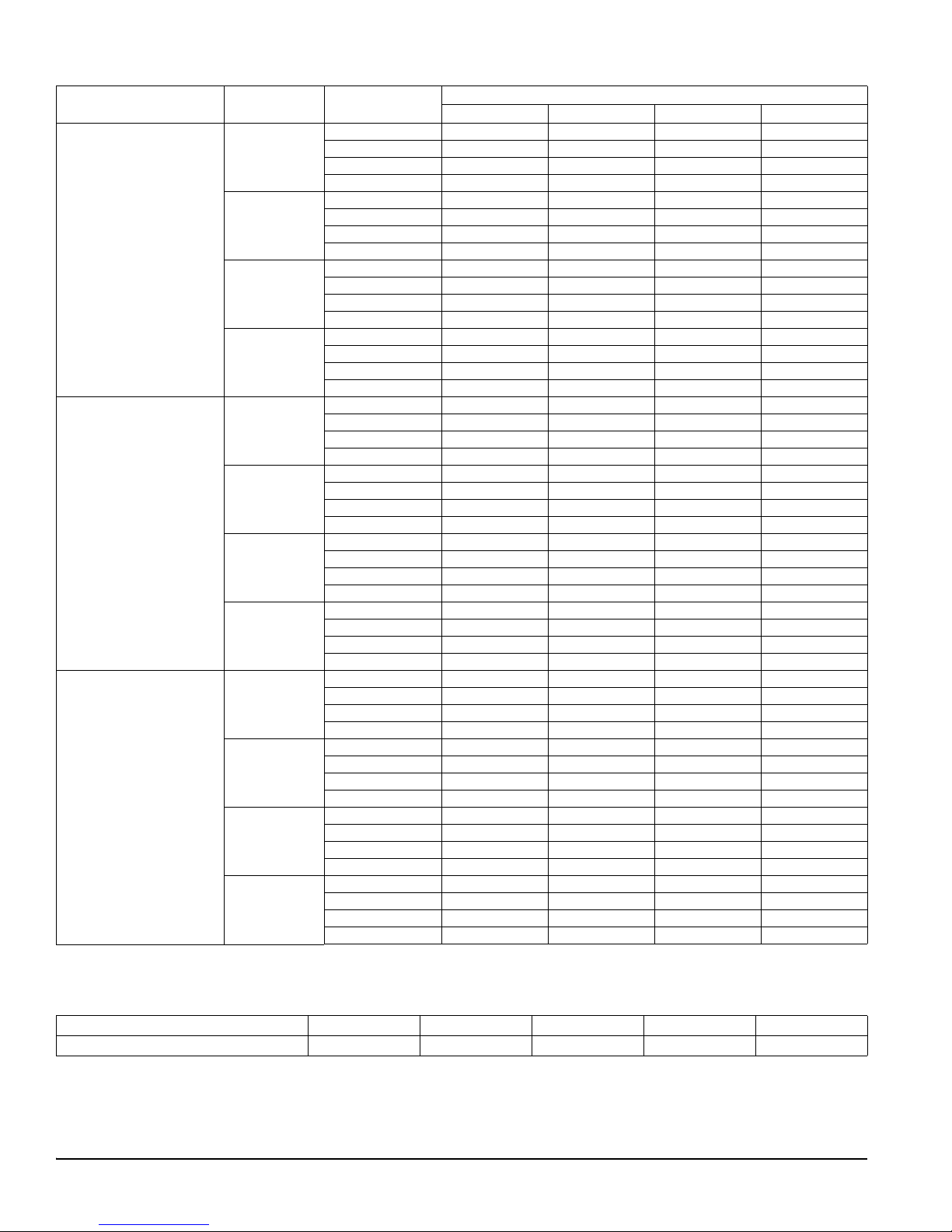
COOLING CAPACITY
Models
AHV42D
AHV48D
AHV60D
1. Actual capacity varies with the outdoor AC or HP that is used with the system.
2. Airflow is calculated for each system tonnage.
1
(Continued)
Rated CFM
820
1000
1180
1385
1000
1195
1385
1600
1190
1390
1565
1835
Entering Air
2
Dry/Wet Bulb (°F)
85/72 56.6 51.1 42.8 35.6
80/67 48.6 41.1 34.8 27.6
75/62 39.4 33 26 18.3
70/57 30.5 26.6 23.1 19.6
85/72 65.7 61 52.7 42.9
80/67 58 49.6 41.1 32.1
75/62 46.7 38.9 30.4 21.8
70/57 36.4 31.6 27.6 23.3
85/72 67.9 71.4 60.2 48.8
80/67 65.6 56.9 47.1 37.1
75/62 53.8 45.2 34.7 24.6
70/57 42.2 37.1 31.9 27.0
85/72 69.4 81 68 57.2
80/67 77.1 65.4 54.1 41.6
75/62 62.1 51 39.8 28.1
70/57 48.1 42.5 36.8 30.6
85/72 69 59.8 51.3 41.5
80/67 56.5 48.2 39.7 29.9
75/62 45.1 36.8 28.3 18.9
70/57 34.4 31 26.8 22.5
85/72 79.5 69.7 59.9 48.6
80/67 65.2 55.5 45.5 34.9
75/62 52.2 42.5 32.6 21.8
70/57 40.1 36.1 31.1 26.2
85/72 90 78.1 66 54.5
80/67 73.5 62.7 51.3 38.7
75/62 59.2 48.2 36.9 24.0
70/57 45.2 41 35.4 29.7
85/72 102.2 90 74.3 60.4
80/67 83.6 70.6 57.2 43.1
75/62 66.1 54 41.2 27.0
70/57 50.7 46.1 39.8 33.4
85/72 83.6 73.7 62.9 51.6
80/67 68.2 58.4 48.4 37.1
75/62 54.9 45.3 34.8 23.9
70/57 42.2 37.3 31.9 26.9
85/72 95.9 84.1 71.9 58.8
80/67 79.2 67.4 54.4 41.6
75/62 62.4 51.2 39.7 26.9
70/57 48 42.5 36.8 30.6
85/72 106.3 94.2 78.5 63.5
80/67 87.6 73.9 60.2 45.9
75/62 69.3 56.8 43.5 29.7
70/57 53.1 46.9 40.5 34.1
85/72 122.1 107.1 90.9 72.6
80/67 100.2 85.9 69.8 51.8
75/62 79.7 65.3 49.8 32.9
70/57 60.8 54.1 46.4 38.7
MBH@ Evap. Temp. and Corresponding R-410A Pressure (°F/PSIG)
35/107.9 40/118.9 45/130.7 50/143.3
APPLICATION FACTORS - RATED CFM VS. ACTUAL CFM
% Of Rated Airflow (CFM)
Capacity Factor
4 Johnson Controls Unitary Products
80% 90% 100% 110% 120%
0.96 0.98 1.00 1.02 1.03
Page 5
824756-BTG-C-0912
PHYSICAL & ELECTRICAL DATA - COOLING ONLY
AHV MODELS
Models
Blower - Diameter x Width
Motor
HP
Nominal RPM
Voltage
Full Load Amps @230V
18B 24B 30B 36C 42D 48D 60D
10 x 8 10 x 8 10 x 8 11 x 10 11 x 10 11 x 10 11 x 10
1/3 HP 1/3 HP 1/3 HP 1/2 HP 1/2 HP 3/4 HP 3/4 HP
1050 1050 1050 1050 1050 1050 1050
208/230 208/230 208/230 208/230 208/230 208/230 208/230
2.3 2.3 2.3 3.2 3.2 4.9 4.9
Type DISPOSABLE OR PERMANENT
1
Filter
Size
Permanent Type Kit
Shipping /
Operating Weight (lbs.)
1. Field supplied.
16 x 20 x 1 16 x 20 x 1 16 x 20 x 1 20 x 20 x 1 22 x 20 x 1 22 x 20 x 1 22 x 20 x 1
1PF0601BK 1PF0601BK 1PF0601BK 1PF0602BK 1PF0603BK 1PF0603BK 1PF0603BK
116/104 121/106 121/106 153/138 169/151 172/154 175/157
KW & MBH CONVERSIONS - FOR TOTAL POWER INPUT REQUIREMENT
For a power distribution voltage that is different than the provided nominal voltage, multiply the kW and MBH d ata from the table by
the conversion factor in the following table.
DISTRIBUTION POWER NOMINAL VOLTAGE CONVERSION FACTOR
208V 240V 0.75
220V 240V 0.84
230V 240V 0.92
ELECTRICAL DATA - COOLING ONLY
Models
Motor FLA
1
208V 230V 208V 230V
Minimum Circuit Ampacity
MOP
2
AHV18B
AHV24B
2.7 2.3 3.4 2.9 15 14
AHV30B
AHV36C
AHV42D
AHV48D
AHV60D
1. FLA = Full Load Amps.
2. MOP = Maximum Overcurrent Protection device; must be HACR type circuit breaker or time delay fuse.
3. 75C, copper wire only. If wire other than non-plated, 75C ambient, copper wire is used, consult applicable tables of the NEC and local codes..
ELECTRICAL HEAT: MINIMUM FAN SPEED
Heater Kit Models
2,3
3.6 3.2 4.5 4.0 15 14
5.3 4.9 6.6 6.1 15 14
1
Nom. kW
@240V
AHV18B AHV24B AHV30B AHV36C AHV42D AHV48D AHV60D
Air Handler Models
6HK(0,1)6500206 2.4kW Low (D) Low (D) Low (D) Low (D) Low (D) Low (D) Low (D)
6HK(0,1)6500506 4.8kW Low (D) Low (D) Low (D) Low (D) Low (D) Low (D) Low (D)
6HK(0,1)6500806 7.7kW Med-Low (C) Low (D) Low (D) Low (D) Low (D) Low (D) Low (D)
6HK(0,1)6501006
6HK06501025
9.6kW Med-Low (C) Low (D) Low (D) Low (D) Low (D) Low (D) Low (D)
6HK(1,2)6501306 12.5kW - Med-Low (C) Med-Low (C) Low (D) Low (D) Low (D) Low (D)
6HK(1,2)6501506
6HK06501525
6HK(1,2)6501806
6HK06501825
6HK(1,2)6502006
6HK16502025
6HK(1,2)6502506
6HK16502525
1. The referenced letter in this table is for the heat jumper tap.
2. (0,1) - 0 = no circuit breaker OR 1 = with circuit breaker.
3. (1,2) - 1 = with circuit breaker, no breaker jumpe r bar OR 2 = with circuit breaker & breaker jumper bar.
14.4kW - Med-Low (C) Med-Low (C) Med-Low (C) Low (D) Low (D) Low (D)
17.3kW - - - Med-Low (C) Med-Low (C) Low (D) Low (D)
19.2kW - - - Med-High (B) Med-High (B) Low (D) Low (D)
24kW------Low (D)
Minimum Wire
Size (AWG)
3
Johnson Controls Unitary Products 5
Page 6

824756-BTG-C-0912
ELECTRIC HEAT PERFORMANCE DATA: 208/230-1-60 & 208/230-3-60
Heater
Models
1,2
Nominal kW
@240V
Total Heat
kW MBH W1 Only W1 + W2
208V 230V 208V 230V 208V 230V 208V 230V
6HK(0,1)6500206 2.4 1.8 2.2 6.2 7.5 1.8 2.2 1.8 2.2
6HK(0,1)6500506 4.8 3.6 4.4 12.3 15.0 3.6 4.4 3.6 4.4
6HK(0,1)6500806 7.7 5.8 7.1 19.7 24.1 5.8 7.1 5.8 7.1
6HK(0,1)6501006 9.6 7.2 8.8 24.6 30.1 7.2 8.8 7.2 8.8
1PH
6HK(1,2)6501306 12.5 9.4 11.5 32.0 39.2 3.1 3.8 9.4 11.5
6HK(1,2)6501506 14.4 10.8 13.2 36.9 45.1 3.6 4.4 10.8 13.2
6HK(1,2)6501806 17.3 13.0 15.9 44.3 54.2 6.5 7.9 13.0 15.9
6HK(1,2)6502006 19.2 14.4 17.6 49.2 60.2 7.2 8.8 14.4 17.6
6HK(1,2)6502506 24.0 18.0 22.0 61.5 75.2 7.2 8.8 18.0 22.0
6HK06501025 9.6 7.2 8.8 24.6 30.1 7.2 8.8 7.2 8.8
6HK06501525 14.4 10.8 13.2 36.9 45.1 10.8 13.2 10.8 13.2
3PH
6HK06501825 17.3 13.0 15.9 44.3 54.2 13.0 15.9 13.0 15.9
6HK16502025 19.2 14.4 17.6 49.2 60.2 7.2 8.8 14.4 17.6
6HK16502525 24.0 18.0 22.0 61.5 75.2 9.0 11.0 18.0 22.0
1. (0,1) - 0 = no circuit breaker OR 1 = with circuit breaker.
2. (1,2) - 1 = with circuit breaker, no breaker jumper bar OR 2 = with circuit breaker & breaker jumper bar.
3. For different power distributions, see conversion table on Page 5.
3
kW Staging
6 Johnson Controls Unitary Products
Page 7

824756-BTG-C-0912
ELECTRICAL DATA FOR SINGLE SOURCE POWER SUPPL Y - 208/230-1-60
Heater
Amps
@240V
Min. Circuit Ampacity
208V 230V 208V 230V 208V 230V
Air Handler Models
Heater
Models
1,2
6HK(0,1)6500206 10.0 14.2 15.4 15 20 12 12
AHV18B
6HK(0,1)6500506 20.0 25.0 27.9 30 30 10 10
6HK(0,1)6500806 32.0 38.0 42.9 40 45 8 8
6HK(0,1)6501006 40.0 46.7 52.9 50 60 8 6
6HK(0,1)6500206 10.0 14.2 15.4 15 20 12 12
6HK(0,1)6500506 20.0 25.0 27.9 30 30 10 10
AHV24B
AHV30B
6HK(0,1)6500806 32.0 38.0 42.9 40 45 8 8
6HK(0,1)6501006 40.0 46.7 52.9 50 60 8 6
6HK(1,2)6501306 52.0 59.7 67.9 60 70 6 4
6HK(1,2)6501506 60.0 68.4 77.9 70 80 4 4
6HK(0,1)6500206 10.0 15.3 16.5 20 20 12 12
6HK(0,1)6500506 20.0 26.2 29.0 30 30 10 10
6HK(0,1)6500806 32.0 39.2 44.0 40 45 8 8
AHV36C
AHV42D
6HK(0,1)6501006 40.0 47.8 54.0 50 60 8 6
6HK(1,2)6501306 52.0 60.8 69.0 70 70 6 4
6HK(1,2)6501506 60.0 69.5 79.0 70 80 4 4
6HK(1,2)6501806 72.0 82.5 94.0 90 100 3 3
6HK(1,2)6502006 80.0 91.2 104.0 100 110 3 3
6HK(0,1)6500206 10.0 17.5 18.6 20 20 12 12
6HK(0,1)6500506 20.0 28.3 31.1 30 35 10 8
6HK(0,1)6500806 32.0 41.3 46.1 45 50 8 8
AHV48D
6HK(0,1)6501006 40.0 50.0 56.1 50 60 8 6
6HK(1,2)6501306 52.0 63.0 71.1 70 80 6 4
6HK(1,2)6501506 60.0 71.6 81.1 80 90 4 4
6HK(1,2)6501806 72.0 84.6 96.1 90 100 4 3
6HK(1,2)6502006 80.0 93.3 106.1 100 110 3 2
6HK(0,1)6500206 10.0 17.5 18.6 20 20 12 12
6HK(0,1)6500506 20.0 28.3 31.1 30 35 10 8
6HK(0,1)6500806 32.0 41.3 46.1 45 50 8 8
6HK(0,1)6501006 40.0 50.0 56.1 50 60 8 6
AHV60D
6HK(1,2)6501306 52.0 63.0 71.1 70 80 6 4
6HK(1,2)6501506 60.0 71.6 81.1 80 90 4 4
6HK(1,2)6501806 72.0 84.6 96.1 90 100 4 3
6HK(1,2)6502006 80.0 93.3 106.1 100 110 3 2
6HK(1,2)6502506 100.0 115.0 131.1 125 150 2 1/0
1. (0,1) - 0 = no circuit breaker OR 1 = with circuit breaker.
2. (1,2) - 1 = with circuit breaker, no breaker jumper bar OR 2 = with circuit breaker & breaker jumper bar.
3. MOP = Maximum Overcurrent Protection device; must be HACR type circuit breaker or time delay fuse.
4. Stated sizes are for 75°C, copper wire only. If wire other than non-plated, 75°
C ambient, copper wire is used, consult applicable tables of the
NEC and local codes.
Field Wiring
MOP.
3
Min Wire Size (AWG)
4
Johnson Controls Unitary Products 7
Page 8

824756-BTG-C-0912
ELECTRICAL DATA FOR MULTI-SOURCE POWER SUPPLY: 208/230-1-60
MOP
1
1st
3
2nd 3rd
Min. Wire Size (AWG)
3
2nd 3rd
1st
1st
Air
Handlers
Models
AHV24B
AHV30B
Min. Circuit Ampacity
208V 230V 208V 230V 208V 230V
Circuit Circuit Circuit
1st
3
2nd 3rd
1st
3
2nd 3rd
1st
3
2nd 3rd
Heater
Models
Total
Heater
Amps
@240
V
6HK16501306 52.0 22.2 37.6 – 24.6 43.3 – 25 40 – 25 45 – 10 8 – 10 8 –
6HK16501506 60.0 25.1 43.3 – 27.9 50.0 – 30 45 – 30 50 – 10 8 – 10 8 –
6HK16501306 52.0 23.3 37.6 – 25.7 43.3 – 25 40 – 30 45 – 10 8 – 10 8 –
AHV36C
AHV42D
6HK16501506 60.0 26.2 43.3 – 29.0 50.0 – 30 45 – 30 50 – 10 8 – 10 8 –
6HK16501806 72.0 43.5 39.0 – 49.0 45.0 – 45 40 – 50 45 –88–88–
6HK16502006 80.0 47.8 43.3 – 54.0 50.0 – 50 45 – 60 50 –88–68–
6HK16501306 52.0 25.4 37.6 – 27.8 43.3 – 30 40 – 30 45 – 10 8 – 10 8 –
AHV48D
6HK16501506 60.0 28.3 43.3 – 31.1 50.0 – 30 45 – 35 50 – 10 8–88–
6HK16501806 72.0 45.6 39.0 – 51.1 45.0 – 50 40 – 60 45 –88–68–
6HK16502006 80.0 49.9 43.3 – 56.1 50.0 – 50 45 – 60 50 –88–68–
6HK16501306 52.0 25.4 37.6 – 27.8 43.3 – 30 40 – 30 45 – 10 8 – 10 8 –
6HK16501506 60.0 28.3 43.3 – 31.1 50.0 – 30 45 – 35 50 – 10 8–88–
AHV60D
6HK16501806 72.0 45.6 39.0 – 51.1 45.0 – 50 40 – 60 45 –88–68–
6HK16502006 80.0 49.9 43.3 – 56.1 50.0 – 50 45 – 60 50 –88–68–
6HK16502506 100.0 49.9 43.3 21.7 56.1 50.0 25.0 50 45 25 60 50 25 8 8 10 6 8 10
1. MOP = Maximum Overcurrent Protection device; must be HACR type circuit breaker or time delay fuse.
2. Stated sizes are for 75°C, copper wire only. If wire other than non-plated, 75°C ambient, copper wire is used, consult applicable tables of the NEC and local codes.
3. 1st Circuit includes the blower motor amps.
3
2nd 3rd
2
ELECTRICAL DATA FOR SINGLE SOURCE POWER SUPPLY - 208/230-3-60
Heater
Amps
@ 240V
Min. Circuit Ampacity
208V 230V 208V 230V 208V 230V
Air Handler Models
AHV24B
AHV30B
Heater
Models
6HK06501025 23.1 28.4 31.8 30 35 10 8
6HK06501525 34.6 40.9 46.1 45 50 8 8
6HK06501025 23.1 29.5 32.9 30 35 10 8
AHV36C
AHV42D
6HK06501525 34.6 42.0 47.3 45 50 8 8
6HK06501825 41.6 49.6 56.0 50 60 8 6
6HK16502025
3
46.2 54.6 61.8 60 70 6 6
6HK06501025 23.1 31.7 35.0 35 35 8 8
AHV48D
6HK06501525 34.6 44.1 49.4 45 50 8 8
6HK06501825 41.6 51.7 58.1 60 60 6 6
6HK16502025
3
46.2 56.7 63.9 60 70 6 6
6HK06501025 23.1 31.7 35.0 35 35 8 8
6HK06501525 34.6 44.1 49.4 45 50 8 8
AHV60D
1. MOP = Maximum Overcurrent Protection device; must be HACR type circuit breaker or time delay fuse.
2. Stated sizes are for 7 5°C, coppe r wire o nly. If wire other than non-plated, 75°C ambient, copper wire is used, con su lt applicable tables of the NEC and local codes..
3. The 20kW and 25kW heater models (6HK16502025 and 6HK16502525) come with circuit breakers st andard. Single source power MCA and MOP r equirement s are
given here only for reference if used with field installed single point power modification.
6HK06501825 41.6 51.7 58.1 60 60 6 6
6HK16502025
6HK16502525
3
3
46.2 56.7 63.9 60 70 6 6
57.7 69.1 78.3 70 80 4 4
Field Wiring
1
MOP
Min. Wire Size (AWG)
2
8 Johnson Controls Unitary Products
Page 9

824756-BTG-C-0912
UPFLOW
HORIZONTAL RIGHT
HORIZONTAL LEFT
HEAT
HEAT
HEAT
ELECTRICAL DATA FOR MULTI-SOURCE POWER SUPPLY: 208/230-3-60
2nd
MOP
1
1st
Min. Wire Size (AWG)
3
2nd
1st
3
2nd
1st
3
Min. Circuit Ampacity
Air Handler Models
AHV36C
AHV42D
Heater
Models
Total Heater
Amps
@ 240V
6HK16502025 46.2 29.5 25.0 32.9 28.9 30 25 35 30 10 10 8 10
208V 230V 208V 230V 208V 230V
Circuit Circuit Circuit
1st
3
2nd
1st
3
2nd
1st
3
AHV48D 6HK16502025 46.2 31.7 25.0 35.0 28.9 35 25 35 30 8 10 8 10
AHV60D
1. MOP = Maximum Overcurrent Protection device; must be HACR type circuit breaker or time delay fuse.
2. Stated sizes are for 75°C, copper wire only. If wire other than non-plated, 75°C ambient, copper wire is used, co nsult applicable tables of the NEC and local codes.
3. 1st Circuit includes the fan motor.
6HK16502025 46.2 31.7 25.0 35.0 28.9 35 25 35 30 8 10 8 10
6HK16502525 57.7 37.9 31.3 42.2 36.1 40 35 45 40 8888
2
2nd
TYPICAL APPLICATIONS
ACCESSORIES
Refer to Price Manual for specific model numbers where not
shown.
TXV Kits - TXV kits are available for “Flex-coil” applications and
converting R-22 to R-410A or as a service replacement. All kits
are bolt-on and require no brazing to install.
Electric Heaters - 6HK models shown under electrical data
include sequential operation and temperature dual limit
switches for safe, efficient operation. Circuit breakers are provided where shown.
LIMITATIONS
These units must be wired and installed in accordance with all
national and local safety codes.
Voltage limits are as follows:
1
Air Handler Voltage
208/230-1-60 187-253
1. Rated in accordance with ARI Standard 110, utilization range “A”.
Airflow must be within the minimum and maximum limits
approved for electric heat, evaporator coils and outdoor units.
Normal Operating Voltage
Range
Johnson Controls Unitary Products 9
Page 10

824756-BTG-C-0912
Air Handler Control Wiring
Typical A/C - Cooling only Applications
THERMOSTAT
AIR HANDLER
BOARD
1 - STAGE
AIR CONDITIONING
RR
G
Y
W1
W2
C
G
W1
W2
Y
C
Y/Y2
Y1
O
HUM
COM
HUMIDISTAT
THERMOSTAT
AIR HANDLER
BOARD
1 - STAGE
AIR CONDITIONING
RR
G
Y
W1
W2
C
G
W1
W2
Y
C
Y/Y2
Y1
O
HUM
COM
HUMIDISTAT
Air Handler Control Wiring
Typical A/C with Electric Heat Applications
CONTROL WIRING - Air Handler & UPG HP Systems Two Stage
H/P with York Guard VI Board & Copeland “Ultra Tech”
Conventional Application - Not Hot Heat Pump
THERMOSTAT
AIR HANDLER
BOARD
2 - STAGE SCROLL
HEAT PUMP
RR R
GG
Y2
E
W
W
OO
O
X / L X / L
C
C
Y/Y2
Y1
Y1
Y2 OUT
Y2
W2 OUT
W1 OUT
BS
W2
W1
HUM
COM
HUMIDISTAT
*
Y1
A+
R
C
B-
A+
R
C
B-
A+
R
C
B-
R
G
Y/Y2
Y1
W2
W1
O
HUM
COM
Touch Screen
Communicating
Control
Air Handler
Communicating
Control
Air Conditioner/Heat Pump
Communicating Control
TYPICAL THERMOSTAT CONNECTION
Cooling Models with and without Electric Heat Wiring
* Optional dehumidification humidistat switch contacts open on humidity r i se.
NOTES:
1. “Y/Y2” Thermostat wire must be connected for full CFM and applications requiring 60 second blower off delay for SEER enhancement.
2. Remove humidistat jumper on air handler control board.
3. For heat pump applications - set AC/HP jumper on air handler control board to the HP position.
TYPICAL THERMOSTAT WIRING FOR 2-STAGE
HEAT PUMP WITH ECM BLOWER MOTOR
* Optional dehumidification humidistat switch contacts open on humidity r i se.
NOTES:
1. “Y/Y2” Thermostat wire must be connected for full CFM and applications
requiring 60 second blower off delay for SEER enhancement.
2. Remove humidistat jumper on air handler control board.
3. For heat pump applications - set AC/HP jumper on air handler control board
to the HP position.
10 Johnson Controls Unitary Products
AIR HANDLER WITH COMMUNICATING
AC OR HP
FIGURE 1: Air Handler with Communicating AC or HP
Page 11

824756-BTG-C-0912
AIR FLOW DATA (CFM)
Cool Tap
A B 805 523 1035 673 1150 748 1380 897
B B 690 449 920 598 1035 673 1208 794
A A 700 455 900 585 1000 650 1200 780
B A 600 390 800 520 900 585 1050 690
A C 630 410 810 527 900 585 1080 702
C B 575 374 776 506 920 598 1035 673
B C 540 351 720 468 810 527 945 621
D B 460 299 633 414 805 523 863 564
C A 500 325 675 440 800 520 900 585
D A 400 260 550 360 700 455 750 490
C C 450 293 608 396 720 468 810 527
D C 360 234 495 324 630 410 675 441
ADJ Tap
1
High/Low Speed Cooling and Heat Pump CFM
2
AHV18 AHV24 AHV30 AHV36
High Low High Low High Low High Low
Cool Tap
ADJ Tap
2
AHV42 AHV48 AHV60
High Low High Low High Low
A B 1610 1047 1840 1196 2070 1346
B B 1495 972 1668 1093 1811 1179
A A 1400 910 1600 1040 1800 1170
B A 1300 845 1450 950 1575 1025
A C 1260 819 1440 936 1620 1053
C B 1380 897 1495 972 1668 1081
B C 1170 761 1305 855 1418 923
D B 1265 822 1323 863 1570 1024
C A 1200 780 1300 845 1450 940
D A 1100 715 1150 750 1365 890
C C 1080 702 1170 761 1305 846
D C 990 644 1035 675 1229 801
High/Low Speed Heat CFM
Heat Tap
ADJ Tap
2
AHV18 AHV24 AHV30 AHV36
High Low High Low High Low High Low
A Any 850 650 1100 740 1100 740 1360 900
B Any 700 600 960 650 960 650 1150 770
C Any 550 550 830 600 830 600 1000 630
D Any 400 400 580 550 580 550 720 550
Heat Tap
ADJ Tap
2
AHV42 AHV48 AHV60
High Low High Low High Low
A Any 1550 950 1775 1000 2000 1150
B Any 1350 800 1600 850 1840 1050
C Any 1150 670 1360 750 1570 950
D Any 900 550 1170 600 1370 830
1. All CFMs are shown at 0.3" w.c.external static pressure . These units have variable-speed ECM motors that automatically adjust to provide constant CFM from
0.0" to 0.4" wc. external static pressure. From 0.4" to 0.8" externa l static pressure, CFM is r educed by 2% per 0.1" st atic pressure. O peration of th ese units on duct
systems with external static pressure greater than 0.8" is not recommended.
At some settings, airflow may be lower than what is required to operate an airflow switch on certain models of electronic air cleaners. Consult the instructions for
the electronic air cleaner for further details.
Data is for 208V or 230V .
2. The ADJ "D" tap should not be used.
Johnson Controls Unitary Products 11
Page 12

824756-BTG-C-0912
1
2
3
4
5
6
L2
L1
L2
L1
HE1
HE2
LS
LS
HE3
LS
H
H
H
H
FL
FL
FL
5
4
3
1
3
1
SEQ2
SEQ1
RED
EQUIPMENT
GROUND
YEL
BLU
BLK
BLK
RED
RED
YEL
BRN
WHT
BLU
PRP
BLU
BLU
BLU
BLU
1
2
3
4
5
6
L2
L1
L2
L1
HE1
HE2
LS
LS
HE3
LS
H
H
FL
FL
FL
5
4
3
1
SEQ2
SEQ1
RED
EQUIPMENT
GROUND
YEL
RED
YEL
BLK
RED
RED
BLK
BRN
WHT
BLU
PRP
BLU
RED
BLU
BLU
1
2
3
4
5
6
L2
L1
HE2
LS
FL
RLY 2
RLY 1
RED
EQUIPMENT
GROUND
YEL
BLK
BLU
YEL
WHT
BLU
PRP
BLU
BLU
BLU
1
2
3
4
5
6
L2
L1
L2
L1
HE1
HE2
LS
LS
HE3
LS
H
H
H
H
FL
FL
FL
5
4
3
1
4
5
SEQ3
SEQ1
RED
EQUIPMENT
GROUND
BLU
BLK
BLK
RED
RED
BRN
WHT
BLU
PRP
BLU
BLU
H
H
5
4
3
1
SEQ2
BLU
L2
L1
BLU
HE5
LS
FL
HE4
LS
FL
BRN
RED
BLK
BLK
BLU
YEL
YEL
RED
RED
RED
HE4
LS
FL
H
H
5
4
3
1
BLU
BLK
BLU
HE1
LS
FL
BLU
WHT
1
2
3
4
5
6
L2
L1
RLY
RED
EQUIPMENT
GROUND
YEL
BLK
WHT
BLU
PRP
BLU
BLU
HE2
LS
FL
WHEN INSTALLING HEATER KIT, BE SURE THE BLOWER SPEED IS
SET TO THE SPEED SPECIFIED FOR THE AIR HANDLER/HEATER KIT
COMBINATION ON THIS UNIT'S INSTALLATION INSTRUCTIONS.
HEATER KITS:
6HK*6500206
6HK*6500506
HEATER KITS:
6HK*6500806
6HK*6501006
HEATER KITS:
6HK16501306
6HK16501506
HEATER KITS:
6HK16501806
6HK16502006
HEATER KIT:
6HK16502506
24V
240V
COM
208V
XFORMER
HE1
LS
FL
HE2
LS
FL
HE3
LS
FL
HE4
LS
FL
HE5
LS
FL
SEQ or RLY
SEQ
SEQ
SEQ
SEQ or RLY
RED
GRN
BLU
WHT
BRN
USE COPPER CONDUCTORS ONLY.
IF ALUMINUM CONDUCTORS ARE PRESENT,
ALL APPLICABLE LOCAL AND NATIONAL
CODES MUST BE FOLLOWED.
SEE INSTALLATION INSTRUCTIONS FOR PROPER
LOW VOLTAGE FIELD WIRING CONNECTIONS.
LEGEND
LS - LIMIT SWITCH
SEQ - SEQUNECER
HE - HEATING ELEMENT
FL - FUSIBLE LINK
H - SEQUNECER HEATER
RLY - RELAY
TSTAT - WALL THERMOSTAT
H
H
H
H
H
H
COM
NO
NO
NO
COM
COM
818695-UWD-A-1111
208-240 VOLT
13 KW AND ABOVE
10 KW AND BELOW
ECM
BLOWER
MOTOR
C
L
G
N
12345
YEL
EQUIPMENT
GROUND
1
2
3
4
5
6
BLK
RED
{
208-240 VAC 60HZ
1 PHASE SUPPLY
24V
240V
ECM
BLOWER
MOTOR
COM
208V
XFORMER
BLK
RED
BLU
BRN
WHT
GRN
C
L
G
N
12345
RED
BLK
GRY
ECM AIR HANDLER WITH
NO HEAT KIT WIRING DIAGRAM
GRN
9 8 7 6 5 4 3 2 1
8 7 6 5 4 3 2 1
BLU
PRP
ORG
WHT
BRN
YEL/BLK
YEL
GRN
RED
BLU/BLK
BLU
ORG
1
2
3
4
5
6
BLK
RED
BLU/WHT
BRN
WHT
CONTROL
BOARD
TSTAT
TSTAT
WIRING DIAGRAMS
WIRING DIAGRAM - SINGLE PHASE HEAT KITS
12 Johnson Controls Unitary Products
Page 13

824756-BTG-C-0912
HEATER KITS:
6HK06501025
6HK06501525
HEATER KITS:
6HK06501825
HEATER KITS:
6HK16502025
6HK16502525
COMPONENT CODES
GND – EQUIPMENT GROUND
FL – FUSIBLE LINK
HE – HEATING ELEMENT
LS – LIMIT SWITCH
REL – RELAY
FIELD POWER WIRING
(208/230V)
FACTORY WIRING
(208/230V)
FACTORY WIRING
LOW VOLTAGE
L1
L2
L3
L1
L2
L3
GND
GND
GND
GND
L1
L2
L3
L1
L2
L3
REL1
REL2
REL3
REL4
REL5
REL6
HE1
HE6
HE5
HE4HE3
HE2 FL
FL
FL
FL
FL
FL
REL1
REL2
REL3
HE1HE3
HE2FL
FL FL
REL1
REL2
REL3
REL4
REL5
REL6
HE1
HE6
HE5
HE4
HE3
HE2 FL
FL
FL
FL
FL
FL
WIRING DIAGRAM - 3 PHASE HEAT KITS
Johnson Controls Unitary Products 13
Page 14

NOTES
Subject to change without notice. Published in U.S.A. 824756-BTG-C-0912
Copyright © 2012 by Johnson Controls, Inc. All rights reserved. Supersedes: 824756-BTG-B-0612
York International Corp.
5005 York Drive
Norman, OK 73069
 Loading...