

Page 1
ACCESSORY KIT INSTALLATION MANUAL
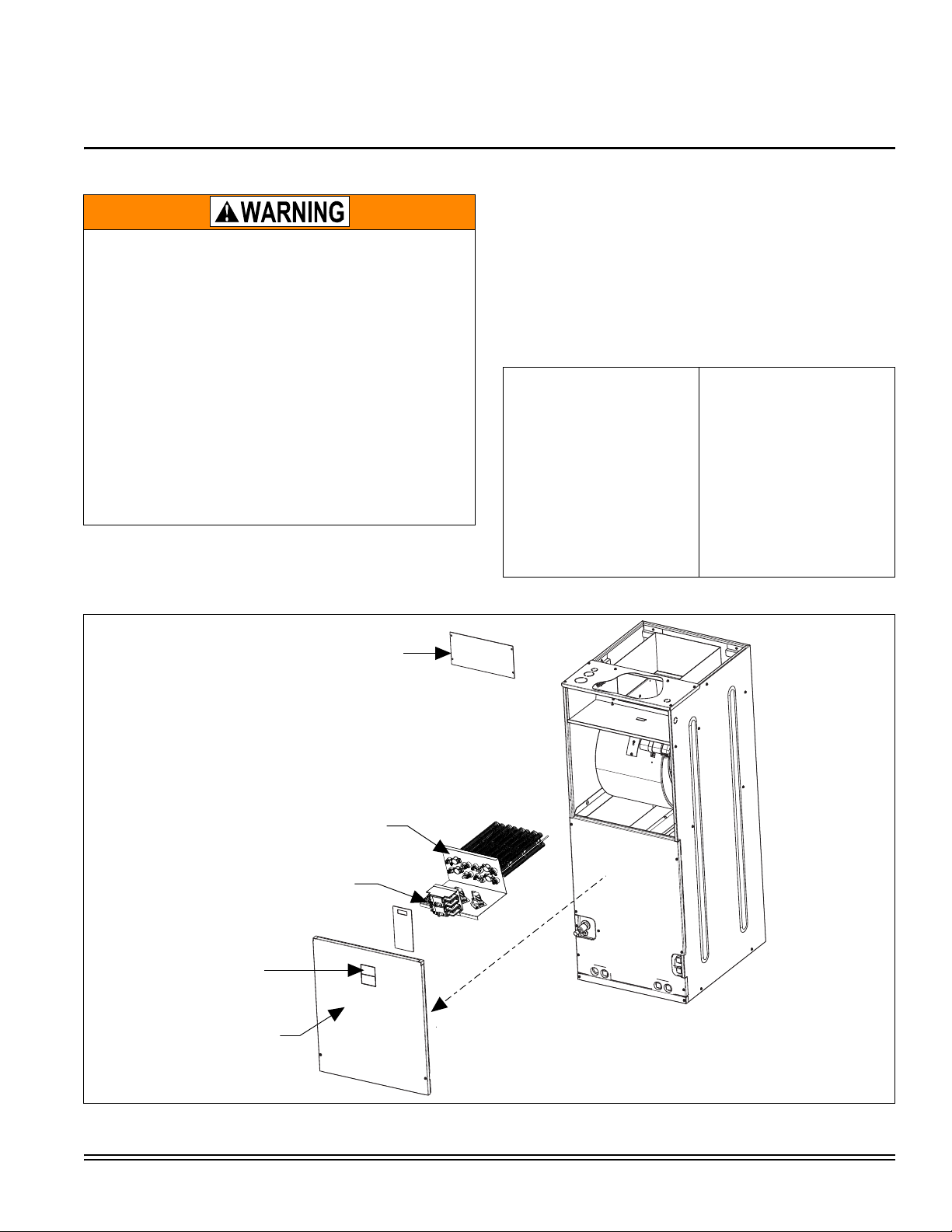
REMOVE
DUCT COVER
3.
FIELD SUPPLY WIRING
THIS SIDE
5.
SLIDE HEATER KIT INTO
AIR HANDLER AND ATTACH
WITH 4 DUCT COVER SCREWS
4.
BLOWER
ACCESS PANEL
2.
REMOVE
IF HEAT KIT TO BE INSTALLED
HAS CIRCUIT BREAKERS,
REMOVE CIRCUIT BREAKER
KNOCKOUTS.
1.
ELECTRIC HEATER ACCESSORY - 6HK SERIES
FOR USE WITH THE FOLLOWING AIR HANDLER
MODELS: AHR / AHE
GENERAL INFORMATION
ELECTRICAL SHOCK HAZARD
Installation or repairs made by unqualified persons can result
in hazards to you and others. Installation must conform with
local building codes or, in the absence of local codes, with
National Electrical Code ANSI/NFPA 70-1996 or current edition.
The information contained in this manual is intended for use
by a qualified service technician familiar with safety procedures and equipped with the proper tools and test instruments.
Shut OFF electric power at unit disconnect and/or service
panel before beginning the following procedures.
Failure to carefully read and follow all instructions in this manual can result in malfunction, property damage, personal
injury, and/or death.
Verify edges of foil faced insulation are not in contact with any
exposed electrical connections.
This instruction covers the physical installation of the following
electric heaters with AHR/AHE18-60 single piece air handlers.
Refer to unit instructions for electrical specifications.
These electric heat accessories are used for applications of
cooling with electric heat and heat pump with electric heat.
Each of the air handler unit models are approved for use with
specific electric heat accessories. The Air Handler installation
instructions, or name plate list the possible combinations and
other important electrical data and limitations.
TABLE 1: Models Covered*
6HK06500206
6HK16500206
6HK06500506
6HK16500506
6HK06500806
6HK16500806
6HK06501006
6HK16501006
6HK16501306
6HK16501506
6HK16501806
6HK16502006
* Refer to Page 4 for nomenclature.
6HK16502506
6HK06501525
6HK06501825
6HK16501825
6HK16502025
6HK16502525
6HK26501306
6HK26501506
6HK26501806
6HK26502006
6HK26502506
FIGURE 1: Heater Installation
Johnson Controls Unitary Products 669997-UAI-D-1111
Page 2
669997-UAI-D-1111
NOTICE
FIELD SUPPLY WIRING WILL
BE ATTACHED TO THIS SIDE
CIRCUIT BREAKERS
May be 1, 2, or 3)
UNIT WIRING ATTACHED
TO THIS SIDE
(Do not need to remove)
INSTALLATION
Installation is the same for all operating positions: upflow, horizontal right or left (Refer to Figure 1). Installation of the Heater
Kit should be done prior to unit installation.
1. If Heat Kit has circuit breakers - remove circuit breaker
knockouts from front of air handler unit. For kits with circuit
breakers, cut blower access panel insulation along foil
perforations behind the circuit breaker plate and remove to
open the area for the circuit breakers to protrude through
the front access panel and to provide clearance for circuit
breakers and single point wiring entry kit. Replacement
non-foil faced insulation for the exposed fron t panel may
then need to be added. Add rubber gasket to inside of
door.
2. Remove air handler blower access panel.
3. Remove duct cover from back panel of air handler control
and wiring compartment.
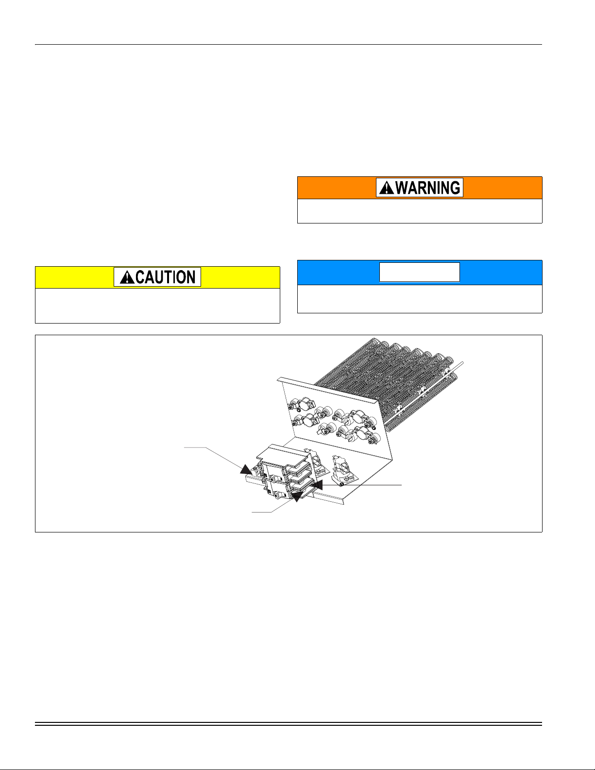
To prevent damage, carefully pass the accessory heating element through the rectangular opening in the discharge duct.
Element mounting plate must be secured with 4 screws.
4. Install electric heat accessory.
a. Position and slide heat kit into opening in air handler.
b. Align holes and fasten the Heat Kit to the air handler
unit with 4 screws.
5. Connect the Heat Kit’s 6 pin socket connector to the appropriate 6 pin connector in the air handler. The end terminals
are “D” shaped to ensure polarization of the connector.
6. Connect the air handler power supply to either the circuit
breaker or terminal block.
Verify edges of foil faced insulation are not in contact with any
exposed electrical connections.
7. Mark an X in the appropriate box on the indoor unit data
plate for the particular heater installed.
All wiring must comply with local and national electrical code
requirements. Read and heed all unit caution labels.
FIGURE 2: Heat Kit Connection
LINE POWER CONNECTIONS
Power may be brought into the unit through the outlet air end of
the unit (top left when unit is vertical) or the left side panel.
minimize
Field wiring connects to heat kits with circuit breaker or terminal
block. A ground lug is also provided on the kits.
2 Johnson Controls Unitary Products
air leakage, seal the
field
wiring entry point
.
ELECTRIC HEATERS & OPERATING
CONTROLS
To
The low voltage transformer and the fan control are standard on
all models. The air handlers are shipped pre-wired to operate
as cooling only applications.
Page 3
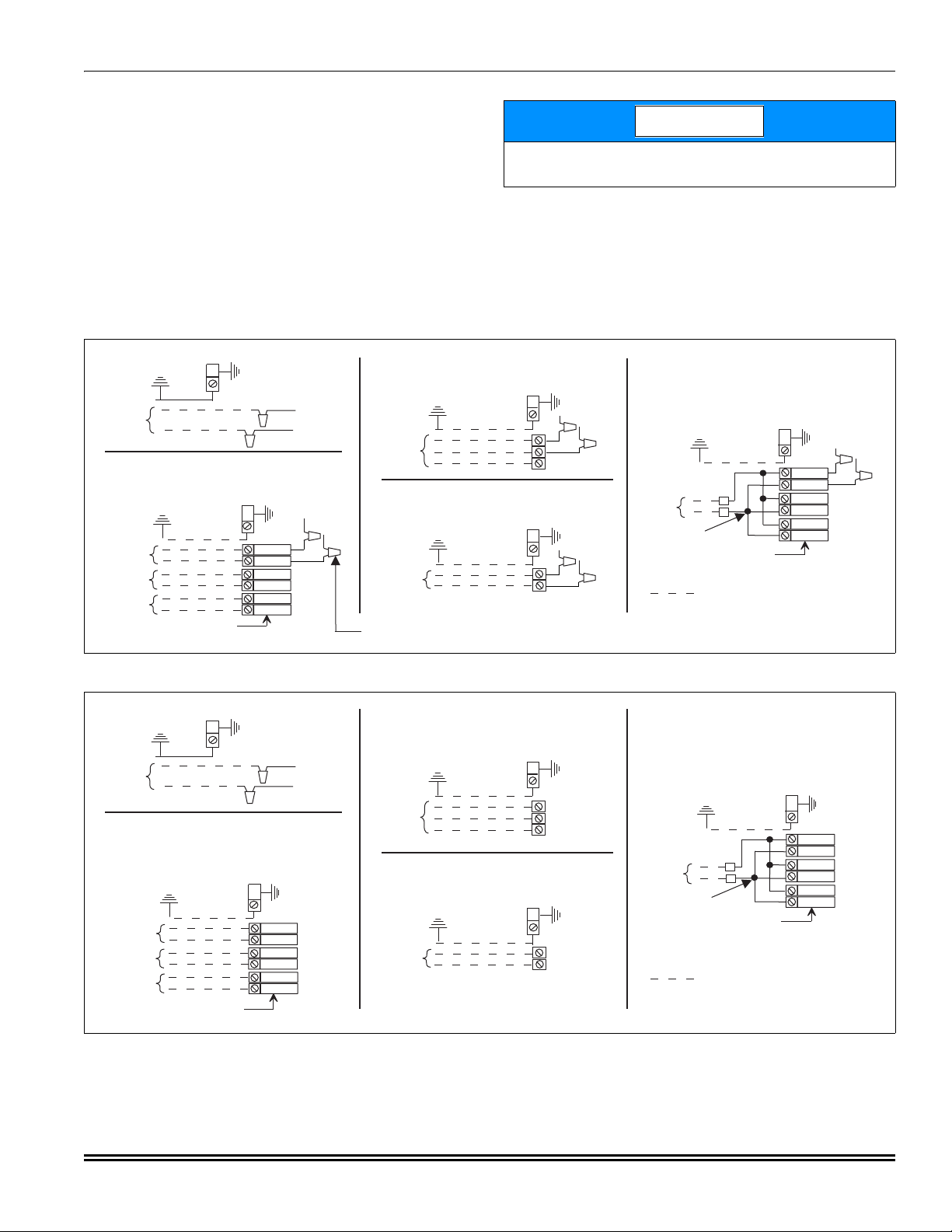
LOW VOLTAGE CONTROL CONNECTIONS
NOTICE
ELECTRIC HEAT
WITHOUT CIRCUIT BREAKER
SINGLE SOURCE (2.5 - 10 KW)
GND. LUG
POWER
SUPPLY
GND.
LUG
ELECTRIC HEAT
WITHOUT CIRCUIT BREAKER
3 PHASE (10 - 18 KW)
GND. LUG
POWER
SUPPLY
GND.
LUG
1 PHASE ELECTRIC HEAT
WITH CIRCUIT BREAKER
AS SHIPPED FROM FACTORY
SINGLE SOURCE
(2.5 - 25 KW) - 25 KW SHOWN
GND. LUG
POWER
SUPPLY
GND.
LUG
1 PHASE ELECTRIC HEAT
WITH CIRCUIT BREAKER
& BREAKER BAR REMOVED
MULTI-SOURCE (15 - 25 KW) - 25 KW SHOWN
GND. LUG
POWER
SUPPLY 1
GND.
LUG
POWER
SUPPLY 2
POWER
SUPPLY 3
TYPICAL WIRING WITHOUT ELECTRIC HEAT
GND. LUG
POWER
SUPPLY
GND.
LUG
POWER WIRING (208/230-1-60)
TERMINAL
BLOCK
TERMINAL
BLOCK
MAY BE 1, 2, OR 3
CIRCUIT BREAKERS
MAY BE 1, 2, OR 3
CIRCUIT BREAKERS
(JUMPER BAR)
CONNECT TRANSFORMER LEADS WITH
WIRE NUTS (TYPICAL ALL HEAT KITS)
ELECTRIC HEAT
WITHOUT CIRCUIT BREAKER
SINGLE SOURCE (2.5 - 10 KW)
GND. LUG
POWER
SUPPLY
GND.
LUG
ELECTRIC HEAT
WITHOUT CIRCUIT BREAKER
3 PHASE (10 - 18 KW)
GND. LUG
POWER
SUPPLY
GND.
LUG
1 PHASE ELECTRIC HEAT
WITH CIRCUIT BREAKER
AS SHIPPED FROM FACTORY
SINGLE SOURCE
(2.5 - 25 KW) - 25 KW SHOWN
GND. LUG
POWER
SUPPLY
GND.
LUG
1 PHASE ELECTRIC HEAT
WITH CIRCUIT BREAKER
& BREAKER BAR REMOVED
MULTI-SOURCE (15 - 25 KW) - 25 KW SHOWN
GND. LUG
POWER
SUPPLY 1
GND.
LUG
POWER
SUPPLY 2
POWER
SUPPLY 3
TYPICAL WIRING WITHOUT ELECTRIC HEAT
GND. LUG
POWER
SUPPLY
GND.
LUG
POWER WIRING (208/230-1-60)
TERMINAL
BLOCK
TERMINAL
BLOCK
MAY BE 1, 2, OR 3
CIRCUIT BREAKERS
MAY BE 1, 2, OR 3
CIRCUIT BREAKERS
(JUMPER BAR)
The 24 volt power supply is provided by an internally wired low
voltage transformer
Field supplied low voltage wiring can exit the unit on the top
right hand corner or the right hand side panel. Refer to Figure 1.
Remove
desired knockout and pierce foil faced insulation to
allow wiring to pass through. Use as small of a hole as possible
to
minimize air leakage. Install a 7/8” plastic bushing in the
selected
inside
wiring
be
hole and keep low voltage wiring as short as possible
the control box. To further minimize air leakage, seal the
entry point at the outside of the unit. The field wiring is to
connected at the screw terminals of the control board.
which is standard on all
air handler
models.
669997-UAI-D-1111
All wiring must comply with local and national electrical code
requirements. Read and heed all unit caution labels.
FIGURE 3: Line Power Connections for PSC Motors
FIGURE 4: Line Power Connections for Standard ECM Motors
Johnson Controls Unitary Products 3
Page 4
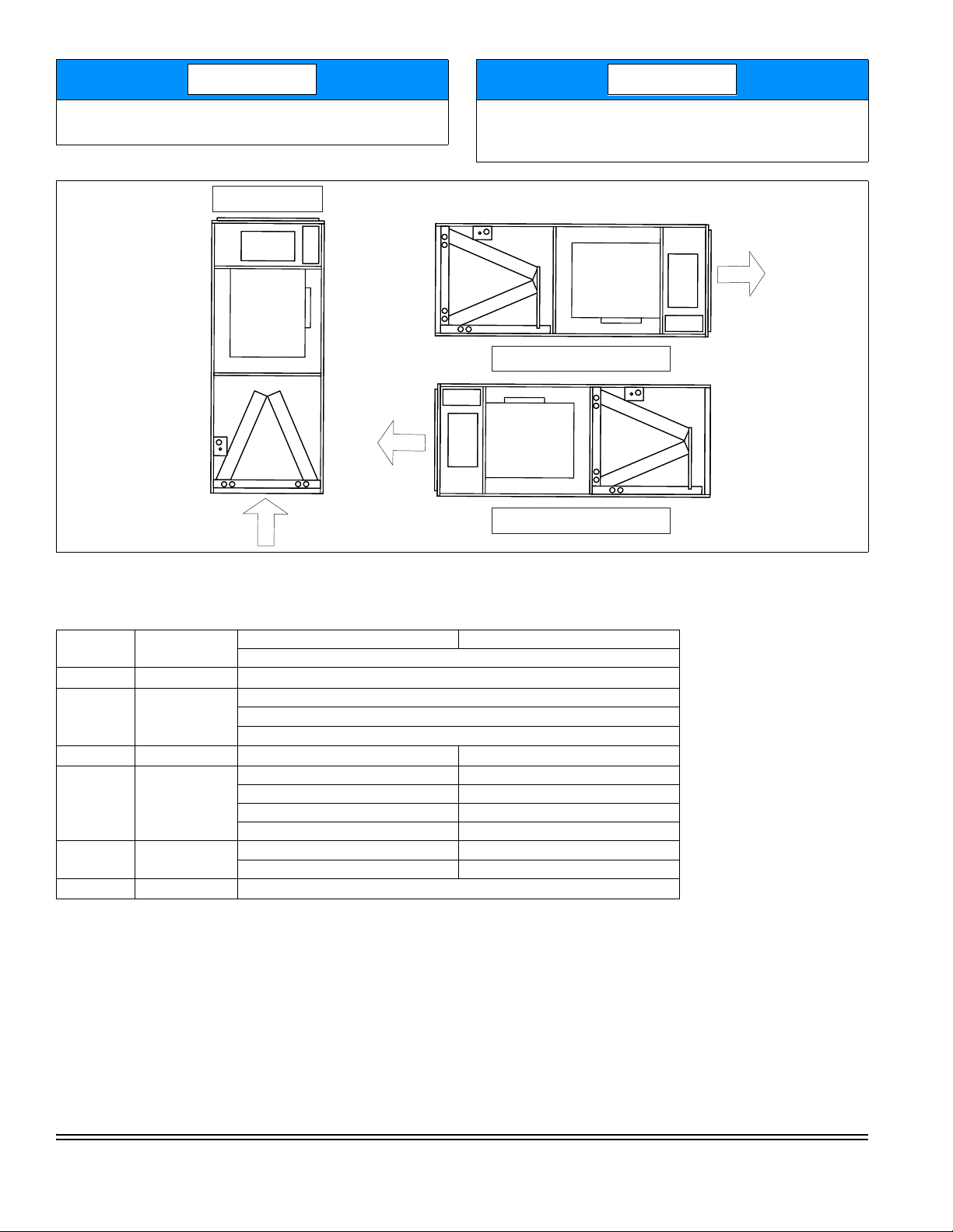
For blower speed connections, electrical information and wir-
NOTICE
NOTICE
UPFLOW
HORIZONTAL RIGHT
HORIZONTAL LEFT
HEAT
HEAT
HEAT
ing diagrams, see indoor unit installation instructions.
FIGURE 5: Typical Installed Application
The electric heaters have both auto resettable and one shot
thermal limit controls. If failure occurs, this one shot thermal
limit control must be replaced with a direct replacement.
NOMENCLATURE - ELECTRICAL
6
HK Family Identifier
06 Where Used
5 Class Identifier
005
06 Voltage Code
BK Order Code
Product Cate-
gory
Electric Heat, in
KW
2 = Electrical Accessory 4 = 2nd Gen Electrical Accessory
6 = 3rd Gen. Electrical Accessory
HK = Heater Kit
06 = Residential Air Handlers for Heat Pump & Air Conditioner
16 = Electric Heater W / Breaker
26 = With Circuit Breaker and breaker jumper
5 = Electric Heat 7 = General
005 = 5 KW 008 = 8 KW
010 = 10 KW 013 = 13 KW
015 = 15 KW 018 = 18 KW
020 = 20 KW 025 = 25 KW
06 = 208 / 230-1-60 25 = 208/230-3-60
24 = 240-1-60 46 = 460-3-60
BK = Bulk Pack (If Applicable)
Subject to change without notice. Published in U.S.A. 669997-UAI-D-1111
Copyright © 2011 by Johnson Controls, Inc. All rights reserved. Supersedes: 669997-UAI-C-0611
Johnson Controls Unitary Products
5005 York Drive
Norman, OK 73069
 Loading...