

Page 1

AD-1272 Advanced Thermal Dispersion Probe Airflow
Measuring System
Technical Bulletin
AD-1272
Refer to the QuickLIT website for the most up-to-date version of this document.
Code No. LIT-12012477
Issued December 2017
Document Introduction. . . . . . . . . . . . . . . . . . . . . . . . . . . . . . . . . . . . . . . . . . . . . . . . . . . . . . .3
Navigating the Start-Up Menu . . . . . . . . . . . . . . . . . . . . . . . . . . . . . . . . . . . . . . . . . . . . . . . . .3
Normal Operation . . . . . . . . . . . . . . . . . . . . . . . . . . . . . . . . . . . . . . . . . . . . . . . . . . . . . . . . . . .4
Configuration. . . . . . . . . . . . . . . . . . . . . . . . . . . . . . . . . . . . . . . . . . . . . . . . . . . . . . . . . . . . . . .5
Membrane Pushbuttons . . . . . . . . . . . . . . . . . . . . . . . . . . . . . . . . . . . . . . . . . . . . . . . . . . . . . .5
Navigating the Menu Options. . . . . . . . . . . . . . . . . . . . . . . . . . . . . . . . . . . . . . . . . . . . . . . . . .5
Navigating the Operator Menu. . . . . . . . . . . . . . . . . . . . . . . . . . . . . . . . . . . . . . . . . . . . . . . . .6
Enable, Disable, and Change the Operator PIN . . . . . . . . . . . . . . . . . . . . . . . . . . . . . . . . . . . . . . 8
Flow Configuration . . . . . . . . . . . . . . . . . . . . . . . . . . . . . . . . . . . . . . . . . . . . . . . . . . . . . . . . . . . . . 9
Display Configuration . . . . . . . . . . . . . . . . . . . . . . . . . . . . . . . . . . . . . . . . . . . . . . . . . . . . . . . . . . 12
Updating Display Configuration . . . . . . . . . . . . . . . . . . . . . . . . . . . . . . . . . . . . . . . . . . . . . . . . . . . . 13
Selecting Custom Text. . . . . . . . . . . . . . . . . . . . . . . . . . . . . . . . . . . . . . . . . . . . . . . . . . . . . . . . . . . 13
Analog Output 1 Parameters . . . . . . . . . . . . . . . . . . . . . . . . . . . . . . . . . . . . . . . . . . . . . . . . . . . . . . 14
Updating Analog Output 1 . . . . . . . . . . . . . . . . . . . . . . . . . . . . . . . . . . . . . . . . . . . . . . . . . . . . . . . . 15
Analog Output 2 Parameters . . . . . . . . . . . . . . . . . . . . . . . . . . . . . . . . . . . . . . . . . . . . . . . . . . . . 16
Updating Analog Output 2 . . . . . . . . . . . . . . . . . . . . . . . . . . . . . . . . . . . . . . . . . . . . . . . . . . . . . . . . 16
Temperature Output LPF (Low Pass Filter). . . . . . . . . . . . . . . . . . . . . . . . . . . . . . . . . . . . . . . . . 17
Updating Temperature Output LPF . . . . . . . . . . . . . . . . . . . . . . . . . . . . . . . . . . . . . . . . . . . . . . . . . 17
Flow Output LPF . . . . . . . . . . . . . . . . . . . . . . . . . . . . . . . . . . . . . . . . . . . . . . . . . . . . . . . . . . . . . . 18
Updating Low Output LPF . . . . . . . . . . . . . . . . . . . . . . . . . . . . . . . . . . . . . . . . . . . . . . . . . . . . . . . . 18
Analog Output Calibration . . . . . . . . . . . . . . . . . . . . . . . . . . . . . . . . . . . . . . . . . . . . . . . . . . . . . . 19
Configuring the Analog Output. . . . . . . . . . . . . . . . . . . . . . . . . . . . . . . . . . . . . . . . . . . . . . . . . . . . . 20
Temperature Balance Configuration . . . . . . . . . . . . . . . . . . . . . . . . . . . . . . . . . . . . . . . . . . . . . . 23
K-Factor Configuration . . . . . . . . . . . . . . . . . . . . . . . . . . . . . . . . . . . . . . . . . . . . . . . . . . . . . . . . . 24
Configuring the K-Factor . . . . . . . . . . . . . . . . . . . . . . . . . . . . . . . . . . . . . . . . . . . . . . . . . . . . . . . . . 25
AD-1272 Advanced Thermal Dispersion Probe Airflow Measuring System
Technical Bulletin
1
Page 2

Menu Timeout. . . . . . . . . . . . . . . . . . . . . . . . . . . . . . . . . . . . . . . . . . . . . . . . . . . . . . . . . . . . . . . . . 30
BACnet Network Configuration . . . . . . . . . . . . . . . . . . . . . . . . . . . . . . . . . . . . . . . . . . . . . . . . . . 31
BACnet Objects . . . . . . . . . . . . . . . . . . . . . . . . . . . . . . . . . . . . . . . . . . . . . . . . . . . . . . . . . . . . . . . . 32
Hardware Objects . . . . . . . . . . . . . . . . . . . . . . . . . . . . . . . . . . . . . . . . . . . . . . . . . . . . . . . . . . . . . . 32
BACnet Flow Alarm Configuration. . . . . . . . . . . . . . . . . . . . . . . . . . . . . . . . . . . . . . . . . . . . . . . . 33
BACnet Temperature Alarm Configuration . . . . . . . . . . . . . . . . . . . . . . . . . . . . . . . . . . . . . . . . . 35
Navigating the Supervisor Menu . . . . . . . . . . . . . . . . . . . . . . . . . . . . . . . . . . . . . . . . . . . . . .37
Enable, Disable, and Change the Supervisor PIN. . . . . . . . . . . . . . . . . . . . . . . . . . . . . . . . . . . . 38
Sensor Management . . . . . . . . . . . . . . . . . . . . . . . . . . . . . . . . . . . . . . . . . . . . . . . . . . . . . . . . . . . 39
Reset Sensor Network. . . . . . . . . . . . . . . . . . . . . . . . . . . . . . . . . . . . . . . . . . . . . . . . . . . . . . . . . . 44
Factory Default Reset . . . . . . . . . . . . . . . . . . . . . . . . . . . . . . . . . . . . . . . . . . . . . . . . . . . . . . . . . . 46
Troubleshooting . . . . . . . . . . . . . . . . . . . . . . . . . . . . . . . . . . . . . . . . . . . . . . . . . . . . . . . . . . .47
AD-1272 Advanced Thermal Dispersion Probe Airflow Measuring System Technical Bulletin
2
Page 3

AD-1272 Advanced Thermal Dispersion Probe Airflow
Figure 1: Front Panel LCD Display of Primary and Wired Remote AD-1272 Transmitter
(Left) and Wireless Remote Display (Right)
Figure 2: Firmware Version
Measuring System
Technical Bulletin
Document Introduction
This document describes the AD-1272 Advanced Thermal Dispersion Probe Airflow Measuring System’s features
and functions. It also provides guidelines and instructions for setting up and troubleshooting these devices used in
plenum and duct applications.
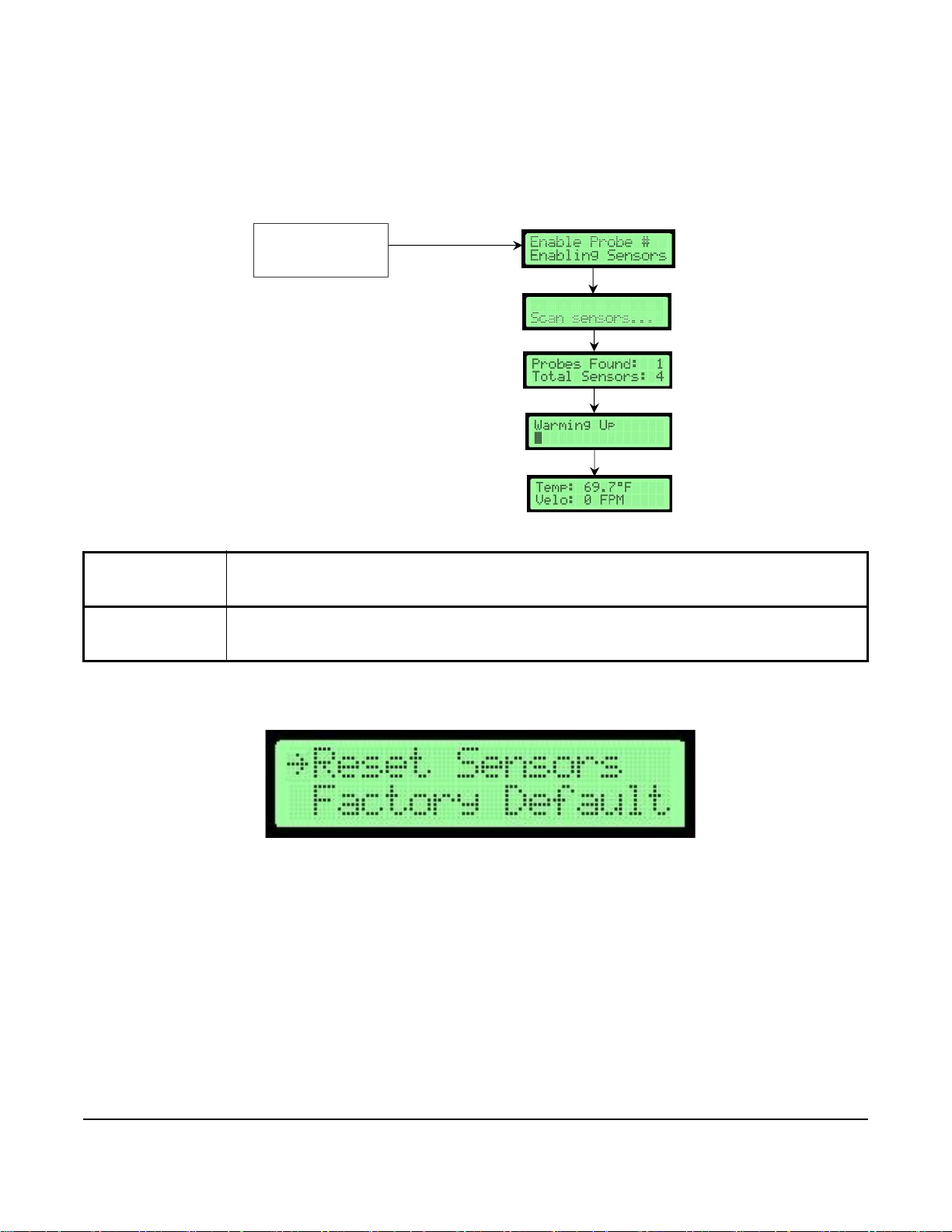
Navigating the Start-Up Menu
After installing the AD-1272 Airflow Measuring System, power on the unit. Menu options appear on the front panel
LCD display of the primary transmitter and are replicated on the Remote Display (see Figure 1). The LCD display
has a 16-character per line, 2-line display.
When the device is first powered on, the display boot screen indicates the firmware version.
AD-1272 Advanced Thermal Dispersion Probe Airflow Measuring System Technical Bulletin
3
Page 4

After 5 seconds, the display indicates the number of active probes and sensors. This example indicates one active
Figure 3: Active Probes and Sensors Screen
Figure 4: Unit is Warming Up Screen
Figure 5: Average Temperature and Velocity Screen
Figure 6: Imperial Temperature and Volume Screen
probe and four total sensors.
Note: When the Primary Transmitter with Display is located remotely, the AD-1272 count the Primary Transmitter
as an additional probe. This will cause the number of probes to be shown as one greater than the number
of ancillary probes.
After another 5 seconds, the display indicates that the unit is warming up.
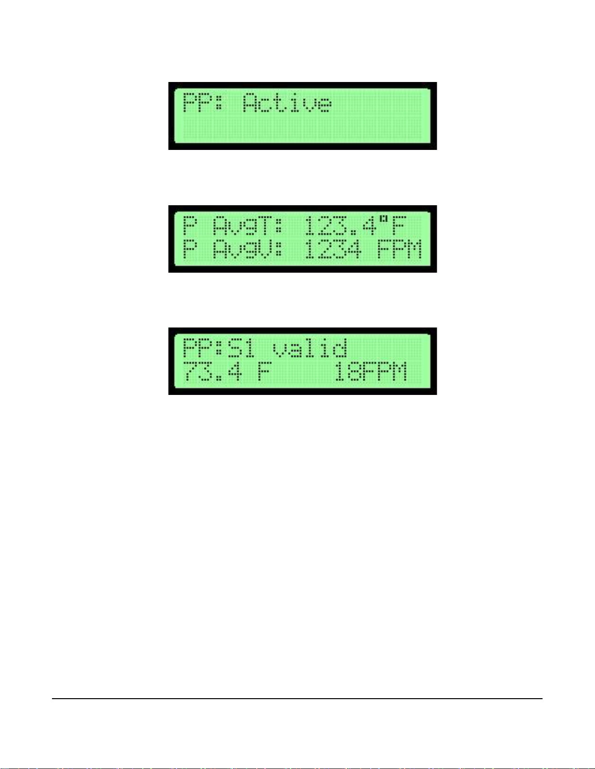
Normal Operation
The normal operation screens display the average temperature and average velocity or volume in the units
selected.
When the display is configured for the International System of Units (SI), the display shows the temperature in
Celsius and the average velocity in meters per second or the volume as liters per minute. See Table 3 for the
available units.
When the display is configured for Imperial, the display shows the temperature in Fahrenheit and the average
velocity in Actual Cubic Feet per Minute. See Table 3 for the available units.
Note: An asterisk (*) appears on the top left corner of the display if the number of sensors has changed during
normal operation mode.
AD-1272 Advanced Thermal Dispersion Probe Airflow Measuring System Technical Bulletin
4
Page 5

Configuration
Figure 7: Membrane Pushbuttons
Figure 8: Menu Option Selection Screen
Figure 9: Adjusting Digits Screen
The onboard microprocessor in the AD-1272 primary transmitter allows for system configuration, operating
parameter selection, analog output configuration, and display filtering.
Note: Each primary and ancillary probe automatically reports temperature and flow based on the number of
installed sensors (1 through 8) per probe.
Verify configuration and change editable parameters, within defined ranges, in the configuration mode.
Membrane Pushbuttons
You can use the five membrane pushbuttons (MENU, ESC, UP, DOWN, and ENTER) on the front panel display
cover to interface with the AD-1272 primary transmitter.
Note: When in Normal Operation Display Mode the second line can be too long to display everything at once.
When this occurs, the display will flash between the value and the unit.
Navigating the Menu Options
The left arrow (→) symbol appears on the left side of the currently selected menu, submenu, or option. Press
ENTER to access the selected option.
The up and down arrow (↕) symbol on line two of the display indicates that the selected digit or character can be
changed one character or digit at a time. The character or digit blinks when selected.
Press the UP or DOWN buttons to scroll through the available menu and submenu options.
Press ESC to return to the previous menu without making updates to the currently selected option. Press ESC from
the Operator or Supervisor Menu to return to normal operation mode.
Press MENU at any time to return to the normal operation mode.
AD-1272 Advanced Thermal Dispersion Probe Airflow Measuring System Technical Bulletin
5
Page 6

To enter numerical values into a submenu selection option, enter the digits one at a time beginning with the
Figure 10: Selecting Operator Menu Screen
Figure 11: Ente ri n g Ope ra tin g PIN Scre en
leftmost digit. Press UP or DOWN to scroll through the numbers 0 through 9. When the correct value is displayed,
press ENTER. The cursor automatically moves to the next position. If an error is made after pressing ENTER,
press ESC to return to the previous digit.
Navigating the Operator Menu
The Operator Menu allows you to view, set, or change system parameters. System configuration setup in the
Operator Menu may be required when connected to a building automation system.
1. During normal operation when the LCD screen displays the average temperature and average velocity or
volume, press MENU and UP or DOWN until the arrow is next to Operator Menu.
2. Press ENTER to enter the Operator Menu submenu options.
a. If the Operator PIN is enabled, the LCD screen displays the following message:
(1) Enter the 4-digit PIN to access the Operator Menu. PIN entry is made one digit at a time beginning with
the leftmost digit. Press UP or DOWN to scroll through the numbers 0 through 9.
(2) When the correct number is displayed, press ENTER to select the digit. The cursor automatically
moves to the next position. If an error is made after you press ENTER, press ESC to go back and
change the digit.
Note: If the PIN is not correctly entered, the display returns to normal operation.
Note: If you misplace your pin, contact JCI technical support.
b. If the Operator PIN is not enabled, the Operator Menu selections display.
Note: See Enable, Disable, and Change the Operator PIN
for more information about enabling the PIN.
3. Press UP or DOWN to scroll through the available menu selections. See Table 1 for a list of Operator Menu
submenus and their descriptions.
Note: Each Operator Menu submenu has submenu selections to access the configurable options.
Table 1: Operator Menu Submenus
Operator Menu
Submenu Description
Submenus (Actual
Display Name)
Enable Operator PIN
(Enable Oper PIN)
Change Operator PIN
(Change Oper PIN)
Allows user to select a PIN to access the Operator Menu and prevents unauthorized access
of the Operator Menu.
Allows user to change the Operator Menu PIN.
AD-1272 Advanced Thermal Dispersion Probe Airflow Measuring System Technical Bulletin
6
Page 7

Table 1: Operator Menu Submenus
Operator Menu
Submenu Description
Submenus (Actual
Display Name)
Flow Configuration
(Flow Config)
Display Configuration
(Display Config)
Analog Output 1
Parameters
(Output 1 Param)
Analog Output 2
Parameters
(Output 2 Param)
Temperature Low Pass
Filter
(Temp LPF)
Flow Low Pass Filter
(Flow LPF)
Analog Output Calibration
(Output Cal Menu)
Temperature Balance
Menu
(Temp Bal Config)
K-Factor Configuration
(K-Factor Config)
Menu Inactivity Timeout
(Menu Timeout)
BACnet Configuration
(Network Cfg)
BACnet Flow Alarm
Configuration
(Flow Alarm Cfg)
BACnet Temperature
Alarm Configuration
(T emp Alarm Cfg)
Exit Operator Menu
(Exit Oper Menu)
Configures system variables including duct size and shape, elevation, process type, and
process maximum/units.
Selects LCD display parameters.
Selects Analog Output 1 parameters including temperature, flow, or none.
Selects Analog Output 2 parameters including temperature, flow, or none.
Selects the amount of filtering applied to the analog output for temperature.
Selects the amount of filtering applied to the analog output for flow.
Adjusts the span for the analog outputs.
Selects an offset to apply to the reported average temperature including front panel display,
BACnet®, and Analog Outputs 1 and 2.
Turns the K-Factor on and off and allows for the calculation or selection of gain and offset
values.
Selects a time period after which the backlight on the front panel display turns off when no
menu activity is detected and automatically returns to normal operation.
Configures BACnet settings and turns BACnet on and off.
Configures high and low setpoints, deadband, and alarm delay settings and turns the BACnet
flow high and low alarms on and off.
Configures high and low setpoints, deadband, and alarm delay settings and turns the BACnet
temperature high and low alarms on and off.
Returns the display to normal operation.
AD-1272 Advanced Thermal Dispersion Probe Airflow Measuring System Technical Bulletin
7
Page 8

Enable, Disable, and Change the Operator PIN
Figure 12: Operator PIN Flowchart
Selected Submenu
*Default value s s hown
Normal Disp lay
Enable Operator
PIN
Change Operator
PIN
MENU
ENTER
ESC or ENTER
ENTER
ESC or ENTER
DOWN
UP
y
The Enable Operator PIN and Change Operator PIN menu options enable or disable the Operator Menu PIN and
change the current PIN.
Note: The PIN is not set or enabled on a device with factory-default settings.
Submenu Selection Displa
Note: If the Enable Operator PIN option is selected, the Operator Menu can only be accessed with a PIN.
To enable or disable the PIN:
1. Enter the Enable Operator PIN submenu.
2. Press UP or DOWN to choose Yes to enable the PIN or No to disable the PIN.
3. Press ENTER to confirm your selection.
To update the PIN:
1. Enter the Change Operator PIN submenu.
2. Press UP or DOWN to scroll through the numbers 0 through 9.
3. When the correct number is displayed, press ENTER to select the digit. The cursor automatically moves to the
next position. If an error is made after pressing ENTER, press ESC to return to the previous digit.
4. Enter the last digit and press ENTER to store the PIN number. The display returns to the Operator Menu
submenu display. Alternatively, press ESC to return to the Operator Menu without updating the PIN.
Note: If the PIN settings are enabled, the PIN number must be entered each time the Operator Menu is entered.
AD-1272 Advanced Thermal Dispersion Probe Airflow Measuring System Technical Bulletin
8
Page 9

Flow Configuration
Figure 13: Flow Configuration Flowchart
1. Duct Area controls area input when the Other duct shape is selected.
2. Range is set in Feet per Minute (FPM), but should be converted to
Cubic Feet Per Minute (CFM) to correspond to the output.
ENTER
ESC
Site Elevation
Relative Humidity
Flow Units
Output Lockout
Exit this Menu
Flow Con?guration
Display
Con?guration Menu
Selected Submenu
Submenu Selec tio ns
Output Lockout
Exit this Menu
Duct Setup
Duct Diameter
010.0 in
Duct Minor Axis
010.0 in
Duct Width
010.0 in
Duct Area
000.69 in
ENTER
ENTER
ENTER
ENTER
ENTER
ENTER
ENTER
ENTER
ENTER
ESC
ESC
ESC
ESC
ESC or Enter
ESC or Enter
ESC or Enter
ESC or Enter
DOWN
DOWN
DOWN
DOWN
DOWN
DOWN
DOWN
UP
UP
UP
UP
UP
UP
UP
Other
Round
Oval
The Flow Configuration submenu stores the application-specific data for unique applications. The typical data
includes units of measure, duct type and size, flow units, site elevation, system ranges, and output lockout.
Submenu Selection Display
ENTER
ENTER
ESC
ENTER
Duct Major Axis
010.0 in
Duct Height
010.0 in
ENTER
ESC
Calc’dDuctArea
0.69 sq ft
ENTER
AD-1272 Advanced Thermal Dispersion Probe Airflow Measuring System Technical Bulletin
9
Page 10

Table 2: Flow Configuration Submenu Selections and Configurable Options
Figure 14: Flow Configuration Selection Screen
Flow Configuration
Submenu
Selections
Duct Shape Select between rectangle, round, oval, or other duct shapes.
Duct Width
Duct Height
Duct Diameter
Duct Area Scroll between 0 to 100 square feet or 0 to 9.3 square meters. A value not stored or an out of range
Site Elevation Select between 0 to 15,000 feet or 0 to 4,572 meters. The units are previously determined.
Relative Humidity Select between 0 and 99% relative humidity 1% at a time. Holding the button increases the speed at
Flow Units Select between the units listed in Table 3.
Output Lockout Enter three digits with two decimal places. Units are in ft/min or m/sec.
1. For oval ducts, width equals major axis and hight equals minor axis. For round ducts, width and height are not used.
2. For rectangular ducts, oval, or other duct types, diameter is not used.
1
1
2
Configurable Options
Select between 0 to 120 in. or 0 to 304.8 cm.
Select between 0 to 120 in. or 0 to 304.8 cm.
Select between 0 to 120 in. or 0 to 304.8 cm.
error displays if the entry exceeds the design range. The units are previously determined.
which the value changes.
1. In the Operator Menu, press UP or DOWN to scroll to the Flow Configuration submenu.
2. Press ENTER.
3. Scroll through the submenu options and make any necessary updates. See Table 2 for a description of the
Flow Configuration submenu selection options and their configurable options.
See Table 3 and Table 4 for the available selections for units appropriate for the flow type.
Table 3: Volumetric Units of Measurement from Flow Unit Selection and Display Units
1
Actual Flow Units
Actual/Sec ACFS ALPS Standard/Sec SCFS SLPS
Actual/Min ACFM ALPM Standard/Min SCFM SLPM
Actual/Hour ACFH ACMH Standard/Hour SCFH SCMH
1. Actual Flow Units is the default setting.
Imperial Units SI Units
Standard Flow
Units
Imperial Units SI Units
Table 4: Volumetric Units of Measurement (Part 1 of 2)
Volumetric Units of Measurement Display
Actual Cubic Feet Per Second ACFS
Actual Cubic Feet Per Minute ACFM
Actual Cubic Feet Per Hour ACFH
Actual Liters Per Second ALPS
Actual Liters Per Minute ALPM
AD-1272 Advanced Thermal Dispersion Probe Airflow Measuring System Technical Bulletin
10
Page 11

Table 4: Volumetric Units of Measurement (Part 2 of 2)
Volumetric Units of Measurement Display
Actual Cubic Meters Per Hour ACMH
Standard Cubic Feet Per Second SCFS
Standard Cubic Feet Per Minute
Standard Cubic Feet Per Hour SCFH
Standard Liters Per Second SLPS
Standard Liters Per Minute SLPM
Standard Cubic Meters Per Hour SCMH
1. The standard conditions for Standard Cubic Feet Per Minute airflow measurements are as follows: 14.696 pounds per
square inch (psi) equals 101.325 kPa at sea level. 70 degrees Fahrenheit equals 21.1 degrees Celsius. 50% relative
humidity (RH).
1
SCFM
AD-1272 Advanced Thermal Dispersion Probe Airflow Measuring System Technical Bulletin
11
Page 12

Display Configuration
Figure 15: Display Configuration Flowchart
Selected Submenu
Submenu Selec ti ons
Submenu Sele ction Display
Display Units
Display
UP
DOWN
ENTER
ENTER
ESC or ENTER
ESC
ENTER
ESC or
ENTER
Display Flow
Type
ENTER
ESC or ENTER
UP
DOWN
Line 2 Parameter
ENTER
UP
DOWN
ESC or ENTER
Line 2 Custom
Text
ENTER
UP
DOWN
ESC or ENTER
Exit this Menu
Returns to
Operator Menu
UP DOWN
ENTER
*Default va lues shown
Display Filter
UP
DOWN
F
I
G
:
f
l
o
w
c
h
a
r
t
_
d
i
s
p
l
a
y
Con iguration
f
The Display Configuration submenu is used to configure display units, parameters, and line 2 customization. The
level of display from 0 to 4 (0 is off, 4 is 80%) is also configurable.
Table 5: Display Configuration Submenu Selections and Configurable Options
Display
Configuration
Submenu
Selections
Display Filter Select between 0 and 4 where 0 is off. Filtering is equal to the value times 20%. A value of 2 is equal
Display Units Select between SI and Imperial.
Display Flow Type Select between velocity and volume.
Line 2 Parameters Select between System Flow and Custom Text for text appearing in line 2 of the display.
Line 2 Custom Select up to seven ASCII characters to display in line 2 of the display. See Selecting Custom Text
Configurable Options
to 40% filtering.
more information.
AD-1272 Advanced Thermal Dispersion Probe Airflow Measuring System Technical Bulletin
12
for
Page 13

Updating Display Configuration
Figure 16: Display Configuration Selection Screen
1. In the Operator Menu, press UP or DOWN to scroll to the Display Configuration submenu.
2. Press ENTER.
3. Scroll through the submenu options and make any necessary updates. See Table 5 for a description of the
Display Configuration submenu selection options and their configurable options.
Selecting Custom Text
1. Scroll to the Line 2 Custom submenu and press ENTER.
AD-1272 Advanced Thermal Dispersion Probe Airflow Measuring System Technical Bulletin
13
Page 14

2. Press UP or DOWN to scroll through the available character set. See Figure 17 for a list of available
Figure 17: Custom Text Character Chart
characters.
3. Press ENTER to choose a character when it is displayed. The character is stored and the cursor advances one
position to the right. Press ESC to return to the previous character.
4. Fill the line with characters for the remaining positions. After the seventh character is entered, the custom text
is stored in memory and the display returns to the Display Configuration submenu.
Analog Output 1 Parameters
The Analog Output 1 Parameters submenu is used to select the process variables that Output 1 represents.
Available process variables include flow, temperature, and none. If flow is selected, the output represents the
defined flow design range.
Note: Default flow is in FPM. See BACnet Network Configuration
AD-1272 Advanced Thermal Dispersion Probe Airflow Measuring System Technical Bulletin
14
for CFM configuration.
Page 15

Note: The factory-default setting for Analog Output 1 is airflow velocity. However, Output 1 or Output 2 can be
Figure 18: Analog Output 1 Parameters Flowchart
Analog Output 1
Parameters
ENTER
ESC or ENTER
*Default values shown
?
Selected Submenu
Submenu Selection Display
Figure 19: Outp u t 1 Parameter Selection Screen
configured for either airflow or temperature.
Table 6: Analog Output 1 Submenu Selection and Configurable Option
Analog Output 1
Submenu
Selection
Output 1
Parameters
Configurable Option
Select between none, flow, and temperature.
Updating Analog Output 1
1. In the Operator Menu, press UP or DOWN to scroll to the Analog Output 1 submenu.
2. Press ENTER.
3. Make any necessary updates to the submenu selection. See Table 6 for a description of the Analog Output 1
submenu selection option and its configurable option.
AD-1272 Advanced Thermal Dispersion Probe Airflow Measuring System Technical Bulletin
15
Page 16
Analog Output 2 Parameters
Figure 20: Analog Output 2 Parameters Flowchart
Analog Output 2
Parameters
ENTER
ESC or ENTER
*Default values shown
?
Selected Submenu
Submenu Selection Display
F
I
G
:
f
l
o
w
c
h
a
r
t
_
a
n
a
l
o
g
2
Figure 21: Outp u t 2 Parameter Selection Screen
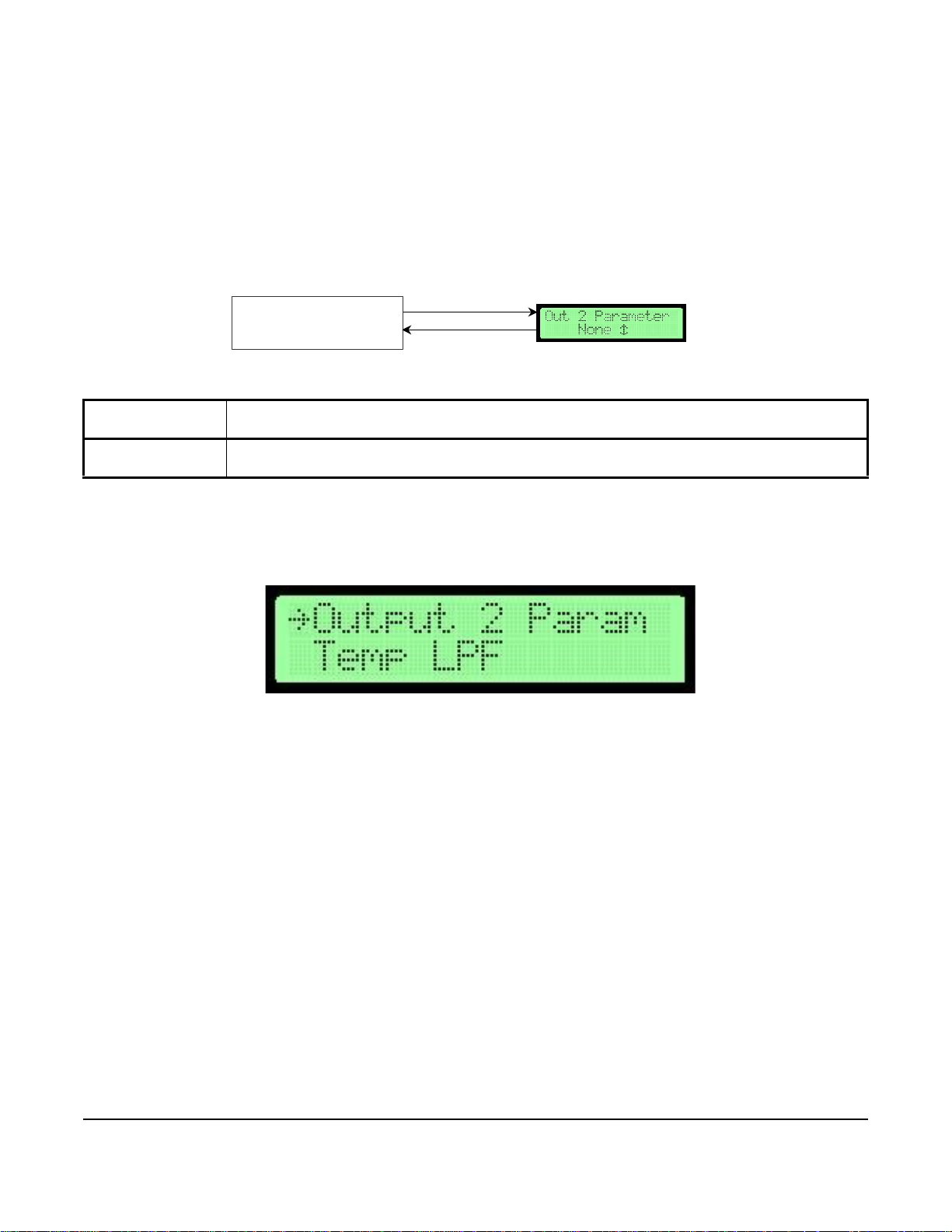
The Analog Output 2 Parameters menu allows you to select the process variables that Output 2 represents.
Available process variables include flow, temperature, and none. If flow is selected, the output represents the
defined flow design range. If temperature is selected, the default output span for temperature is -25.6 to 120.2°F
(-32°C to 49°C).
Note: The factory-default setting for Analog Output 2 is temperature.
Table 7: Analog Output 2 Submenu and Configurable Options
Analog Output 2
Submenu
Output 2
Parameters
Updating Analog Output 2
1. In the Operator Menu, press UP or DOWN to scroll to the Analog Output 2 submenu.
Configurable Option
Select between none, flow, and temperature.
2. Press ENTER.
3. Make any necessary updates to the submenu selection. See Table 7 for a description of the Analog Output 2
submenu selection option and its configurable option.
AD-1272 Advanced Thermal Dispersion Probe Airflow Measuring System Technical Bulletin
16
Page 17

Temperature Output LPF (Low Pass Filter)
Figure 22: Temperature Output LPF Flowchar t
Temperature Output LPF
ENTER
ESC or ENTER
*Default values shown
Selected Submenu
Submenu Selection Display
F
I
G
:
f
l
o
w
c
h
a
r
t
_
t
e
m
p
Figure 23: Temperature Output LPF Selection
The Temperature Output LPF (Low Pass Filter) submenu is used to select the level of process filtering applied to
the temperature outputs. The levels are 0 to 9, with 0 indicating the filter is off and 9 indicating maximum filtering.
The filtering affects the reported temperature values and analog channels configured for temperature. Display Filter
is an additional filter selection applied only to the display.
Note: Each unit of filtering is equal to 10% filtering. For example, 2 is equal to 20%.
Table 8: Temperature Output LPF Submenu Selection and Configurable Option
Temperature Output
LPF Submenu
Selection
Temperature Output
LPF
Updating Temperature Output LPF
Configurable Option
Select between 0 to 9 (9 equals 90% filtering).
1. In the Operator Menu, press UP or DOWN to scroll to the Temperature Output LPF submenu.
2. Press ENTER.
3. Make any necessary updates to the submenu selection. See Table 8 for a description of the Temperature
Output LPF submenu selection option and its configurable option.
AD-1272 Advanced Thermal Dispersion Probe Airflow Measuring System Technical Bulletin
17
Page 18

Flow Output LPF
Figure 24: Flow Output LPF Flowchart
Flow Output LPF
ENTER
ESC or ENTER
*Default values shown
Selected Submenu
Submenu Selection Display
F
I
G
:
f
?
l
o
w
c
h
a
r
t
_
w
o
Figure 25: Flow Output LPF Selection Screen
The Flow Output LPF submenu allows the selection of the level of process filtering applied to the flow outputs. The
levels are 0 to 9, with 0 indicating the filter is off and 9 indicating maximum filtering. The filtering affects the reported
flow values and analog channels configured for flow. Display Filter is an additional filter selection applied only to the
display.
Note: Each unit of filtering is equal to 10% filtering. For example, 2 is equal to 20%.
Table 9: Flow Output LFP Submenu Selection and Configurable Option
Flow Output LPF
Submenu
Selection
Flow LPF Selection Select between 0 to 9 (9 equals 90% filtering).
Updating Low Output LPF
1. In the Operator Menu, press UP or DOWN to scroll to the Flow Output LPF submenu.
Configurable Option
2. Press ENTER.
3. Make any necessary updates to the submenu selection option. See Table 9 for a description of the Flow Output
LPF submenu selection option and its configurable option.
AD-1272 Advanced Thermal Dispersion Probe Airflow Measuring System Technical Bulletin
18
Page 19

Analog Output Calibration
Figure 26: Analog Output Calibration Flowchart
Output 1 Low
Span
UP
DOWN
ESC or ENTER
ESC
ENTER
Output 2 Offset
ESC or ENTER
UP
DOWN
Output 2 Low
Span
UP
DOWN
ESC or ENTER
UP
Low
ESC
DOWN
UP
Output 1 High
Span
ESC or ENTER
ENTER
Output 2 High
Span
ESC or ENTER
ENTER
UP
Design Range
High
ESC
UP
Output 1 Offset
Temperature
Range Low
ESC
UP
ESC
UP
Exit this Menu
UP
Output Calibration
DOWN
UP
?
?
Temperature
Range High
f
i
:
f
g
l
o
w
c
h
a
r
t
_
a
n
a
l
o
g
Analog
Used to adjust the Analog Output Calibration submenu is used to configure the offset and span of Analog Outputs
1 and 2. Span is used to obtain the greatest resolution over the expected or design operating range.
Selected Submenu
ENTER
Submenu Selections Submenu Selection Display
Design Range
AD-1272 Advanced Thermal Dispersion Probe Airflow Measuring System Technical Bulletin
19
DOWN
DOWN
DOWN
DOWN
DOWN
DOWN
ENTER
ENTER
ESC or
ENTER
ENTER
ENTER
ENTER
ENTER
ENTER
ENTER
*Default values shown
Temp Range Hi
Exit this Menu
Page 20

.
Figure 27: Output 1 mA Offset Selection Screen
Figure 28: Anal o g Outp u t 1 Disp la y Scre en
Table 10: Analog Output Calibration Submenu Selections and Configurable Options
Analog Output Calibration
Submenu Selections
Output 1 mA Offset Select between -2 to 2 mA adjustment range.
Output 1 mA Low Span Select between 1 to 4 mA.
Output 1 mA High Span Select between 1 to 20 mA. This value must be higher than the low span value of Output 1.
Output 2 mA Offset Select between -2 to 2 mA adjustment range.
Output 2 mA Low Span Select between 1 to 4 mA.
Output 2 mA High Span Select between 1 to 20 mA. This value must be higher than the low span value of Output 2.
Design Range Low Selects the low range of output flow spanning.
Design Range High Selects the maximum range of output flow spanning.
Temperature Range Low Select between -34.6 to 129.2°F (-37 to 54°C) for low range of output temperature spanning.
Temperature Range High Select between -34.6 to 129.2°F (-37 to 54°C) for maximum range of output temperature
Configurable Options
spanning.
Note: By default, the AD-1272 Airflow Measuring System is factory calibrated.
Configuring the Analog Output
To configure the analog output:
1. Set the Analog Output 1 parameter to None to keep the output from changing with flow or temperature. See
Analog Output 1 Parameters
2. In the Operator Menu, press UP or DOWN to scroll to the Output Calibration submenu.
for instructions.
3. Press ENTER. Scroll to the Output 1 mA Offset submenu selection and press ENTE R.
4. The display indicates the current Analog Output 1 offset.
AD-1272 Advanced Thermal Dispersion Probe Airflow Measuring System Technical Bulletin
20
Page 21

5. Connect a digital multi-meter set to scale Analog Output 1 across terminals plus and minus on the AD-1272
Figure 29: AD-1272 Airflow Measuring System—Terminals 1 and 2
Figure 30: Output 1 mA Low Selection Screen
Figure 31: Output 1 Low Span Display Screen
Airflow Measuring System. See Figure 29 for terminal locations.
Note: The output value should be between 1 and 20 mA. To align the load resistance with the digital multi-meter,
connect the actual process load or a resistor of similar value to the actual process load (250 ohm/
minimum). The digital multi-meter should read a minimum value of 4.00 ± 0.01 mA as determined in Output
1 Span.
6. Press UP or DOWN to adjust the output. Once the last digit is entered, the digital multi-meter reflects the
adjusted Output 1 offset value.
7. Press UP or DOWN in the Output Calibration submenu to scroll to the Output 1 mA Low Span submenu
selection.
8. Press ENTER. The display indicates the current Output 1 low span value.
9. Press UP and DOWN to scroll between 1 and 4 mA to set the low span value.
Note: The low span value must be set lower than the high span value.
AD-1272 Advanced Thermal Dispersion Probe Airflow Measuring System Technical Bulletin
21
Page 22

10. Once the low span is set, press ENTER. In the Output Calibration submenu, scroll to the Output 1 mA High
Figure 32: Output 1 mA High Span Selection Screen
Figure 33: Output 1 High Span Display Screen
Figure 34: Output Calibration Menu Selection
Span submenu selection and press ENTER.
11. The display indicates the current Analog Output 1 high span value. Press UP or DOWN to set the high span by
scrolling between 1 and 20 mA. The high span value must be higher than the low span value.
12. Once the high span is set, press ENTER to confirm the setting.
13. Set the parameter for Analog Output 1 to its previous value before the calibration process. See
Analog Output 1 Parameters
14. Repeat Steps 1 through 13 for Analog Output 2. In Step 5, connect the digital multi-meter across terminals
A02 plus and minus.
for instructions.
15. After both outputs are configured, as necessary, configure the Design Range Low, Design Range High,
Temperature Range Low, and Temperature Range High submenu selections.
16. In the Operator Menu, press UP and DOWN to scroll to the Analog Output Calibration submenu. Press
ENTER.
17. Scroll through the submenu options and make any necessary updates. See Table 10 for a description of the
Analog Output Calibration submenu selection options and their configurable options.
AD-1272 Advanced Thermal Dispersion Probe Airflow Measuring System Technical Bulletin
22
Page 23

Temperature Balance Configuration
Figure 35: Temperature Balance Flowchart
Temperature Balance
Temperature
Balance Enable
ENTER
ENTER
ESC or ENTER
ESC
*Default values shown
Temperature
ESC or ENTER
ENTER
DOWN
UP
Exit this Menu
DOWN
UP
ENTER
DOWN
UP
Returns to
Operator Menu
Returns to
Operator Menu
Selected Su bme n u
Submenu Selections
Submenu Sele ction Display
F
I
G
:
f
l
o
w
c
h
a
r
t
_
t
e
m
p
_
b
a
l
Offset
Con iguration
f
Figure 36: Temperature Balance Configuration Selection Screen
The Temperature Balance Configuration submenu applies a temperature offset to the displayed and reported
temperature and the temperature used for analog outputs.
Table 11: Temperature Balance Configuration Submenu Selections and Configurable Options
Temperature
Balance
Configuration
Submenu
Selections
Temperature
Balance Enable
Temperature Offset
Selection
Configurable Options
Select On or Off.
Enter the currently selected value. The temperature displayed on the left side of line 2 is the offset and
the value on the right side of line 2 is a live view of the current temperature with the last confirmed
offset value.The offset range is ±5.4°F (±3°C).
1. In the Operator Menu, press UP or DOWN to scroll to the Temperature Balance Configuration submenu.
2. Press ENTER.
Temperature Balance Configuration submenu selection options and their configurable options.
3. Scroll through the submenu options and make any necessary updates. See Table 11 for a description of the
AD-1272 Advanced Thermal Dispersion Probe Airflow Measuring System Technical Bulletin
23
Page 24

K-Factor Configuration
Figure 37: K-Factor Configuration Flowchart
Calculate
K-Factor
K-Factor Enable?
UP
DOWN
ENTER
ESC or ENTER
*Default values shown
ESC
ENTER
Note:
1
Only when
Calculate K-Factor
is set to
No
.
2
Only when Calculat e K- Fac tor is set to
Yes
3
Only when # of Data Points is set to
1
or higher
4
Only when # of Data Points is set to
2
or higher.
5
Only when # of Data Points is set to
3
.
ENTER
ESC
K-Factor Gain
1
UP
DOWN
ESC
ENTER
K-Factor Offset
1
UP
DOWN
ESC
ENTER
of Data Points
2
UP
DOWN
ESC
ENTER
System at
UP
DOWN
3 seconds
Veloc ity
UP
DOWN
ESC
ENTER
System at
UP
DOWN
3 Seconds
UP
DOWN
ESC
ENTER
System at
3
2,5
UP
DOWN
3
Seconds
3
2,5
UP
DOWN
ESC
ENTER
Generate K-Factor
2
UP
DOWN
Exit this Menu
UP
DOWN
DOWN
UP
.
.
Returns to
Operator Menu
Selected Submenu
Submenu Selections
Submenu Selection Display
F
I
G
:
f
l
o
w
c
h
a
r
t
_
K
f
a
c
t
o
r
Point
Point
2
2,4
Point
2
2,4
Point
1
2,3
Point
1
2,3
Point
K-Factor?
Number
Con iguration
f
Veloc ity
Veloc ity
The K-Factor Configuration submenu turns K-Factor on and calculates a K-Factor gain and offset from measured
and reference data. The K-Factor gain and offset values can also be manually configured.
AD-1272 Advanced Thermal Dispersion Probe Airflow Measuring System Technical Bulletin
24
Page 25

Table 12: K-Factor Configuration Submenu Selections and Configurable Options
Figure 38: K-Factor Configuration Selection Screen
Figure 39: K-Factor Enable Selection Screen
K-Factor
Configuration
Submenu
Selections
K-Factor Enable? Select On or Off.
Calculate K-Factor Select between Yes or No.
Manual Gain
Manual Offset
1
1
Number of Data
2
Points
System at Point 1
Point 1 Velocity
System at Point 2
Point 2 Velocity
System at Point 3
Point 3 Velocity
Generate K-Factor
Configurable Options
Update the currently selected value.
Update the currently selected value.
Select between one to three points for calculating the K-Factor.
2
Record the current velocity over the sensors as reference point 1.
2
Update the currently selected value. Reference point 1 is displayed on the right side and the
measured value is entered on the left.
2
Record the current velocity over the sensors as reference point 2.
2
Update the currently selected value. Reference point 2 is displayed on the right side and the
measured value is entered on the left.
2
Record the current velocity over the sensors as reference point 3.
2
Update the currently selected value. Reference point 3 is displayed on the right side and the
measured value is entered on the left.
2
Calculate and update the K-Factor values used then display the calculated values.
1. This submenu selection only appears when Calculate K-Factor is set to No.
2. This submenu selection only appears when Calculate K-Factor is set to Yes.
Configuring the K-Factor
1. In the Operator Menu, press UP or DOWN to scroll to the K-Factor Configuration submenu.
2. Press ENTER to view the K-Factor Configuration submenu. Scroll to the K-Factor Enable? submenu
selection.
AD-1272 Advanced Thermal Dispersion Probe Airflow Measuring System Technical Bulletin
25
Page 26
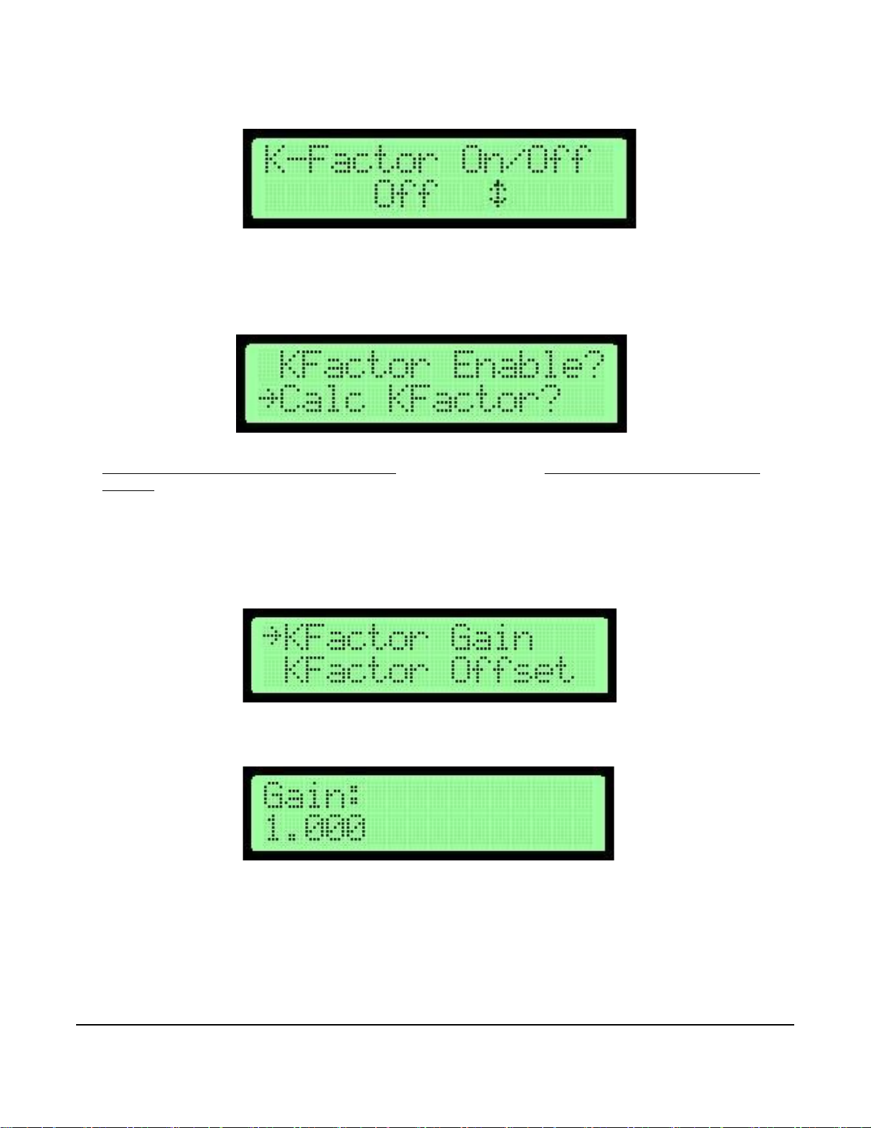
3. Press ENTER. The display indicates the current K-Factor setting (Off or On).
Figure 40: K-Factor Settings Screen
Figure 41: Calculate K-Factor Selection Screen
Figure 42: K-Factor Gain Selection Screen
Figure 43: K-Factor Gain Screen
4. Press UP or DOWN to change the setting and ENTER to confirm the setting. The new setting is stored in
memory and the display returns to the K-Factor Configuration submenu.
5. Press UP or DOWN to scroll to the Calculate K-Factor submenu selection and press ENTER.
6. Press UP or DOWN to scroll between Yes or No. Press EN TER to make a selection. If No is selected, see
Automatic Calculation of K-Factor Not Enabled
Enabled.
. If Yes is selected, see Automatic Calculation of K-Factor
Automatic Calculation of K-Factor Not Enabled
1. When K-Factor is not enabled, the K-Factor Configuration submenu formats itself for manual K-Factor entry
mode. Scroll to the K-Factor Gain submenu selection and press ENTER.
2. Press ENTER to adjust the manual K-Factor gain. Press UP or DOWN to modify the currently selected value.
3. Press ENTER to confirm the value and return to the K-Factor Configuration submenu.
AD-1272 Advanced Thermal Dispersion Probe Airflow Measuring System Technical Bulletin
26
Page 27
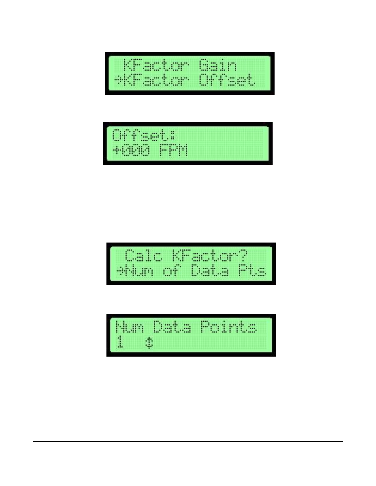
4. Scroll to the K-Factor Offset submenu selection.
Figure 44: K-Factor Offset Selection Screen
Figure 45: K-Factor Gain Screen
Figure 46: Number of Data Point Selection Screen
Figure 47: Number Data Points Adjustment Screen
5. Press ENTER to adjust the manual K-Factor offset. Press UP or DOWN to modify the currently selected value.
6. Press ENTER to confirm the value and return to the K-Factor Configuration submenu.
Automatic Calculation of K-Factor Enabled
Automatic K-Factor calculations can be adjusted to use up to three data points in the calculation. One data point
calculates and uses one offset. Two data points calculate and use one offset and one gain in one equation. Three
data points calculate and use two offsets and two gains in two equations that meet at the middle point.
1. In the K-Factor Configuration submenu, scroll to the Number of Data Points submenu selection.
2. Press ENTER. Press UP or DOWN to select the number of points to use in the K-Factor calculation.
3. Press ENTER to confirm the value and return to the K-Factor Configuration submenu.
AD-1272 Advanced Thermal Dispersion Probe Airflow Measuring System Technical Bulletin
27
Page 28

4. Scroll to the System at Point 1 submenu selection.
Figure 48: System at Point 1 Selection Screen
Figure 49: Point 1 Recorded Velocity Screen
Figure 50: Point 1 Velocity Selection Screen
Figure 51: K-Factor Setpoint Screen
5. Press ENTER. Run the air handling system unit to the first K-Factor setpoint. Once the appropriate velocity is
displayed on the external device, press ENTER to store the sensor data and measured velocity in FPM as the
reference value for calculating the K-Factor equation. The display indicates the value is stored and displays the
value for 3 seconds.
Note: Allow the system at least 60 seconds after a velocity state change to balance the displayed readings.
6. The display returns to the K-Factor Configuration submenu. Scroll to the Point 1 Velocity submenu selection.
7. Press ENTER to enter the first measured K-Factor setpoint that is acquired from an external device. Press UP
or DOWN to modify the currently selected digit.
Note: The left side of the display indicates the measured value and the right side shows the corresponding
reference value that was recorded for that point.
8. Press ENTER on the last digit to confirm the value and return to the K-Factor Configuration submenu.
9. If the number of data points from Step 2 was set for more than one, repeat Steps 4 through 8 for each point.
Point 2 must be higher than point 1 and point 3 must be higher than point 2. When all points are recorded,
continue to Step 10.
10. Press UP or DOWN to scroll to the Generate K-Factor submenu selection.
AD-1272 Advanced Thermal Dispersion Probe Airflow Measuring System Technical Bulletin
28
Page 29
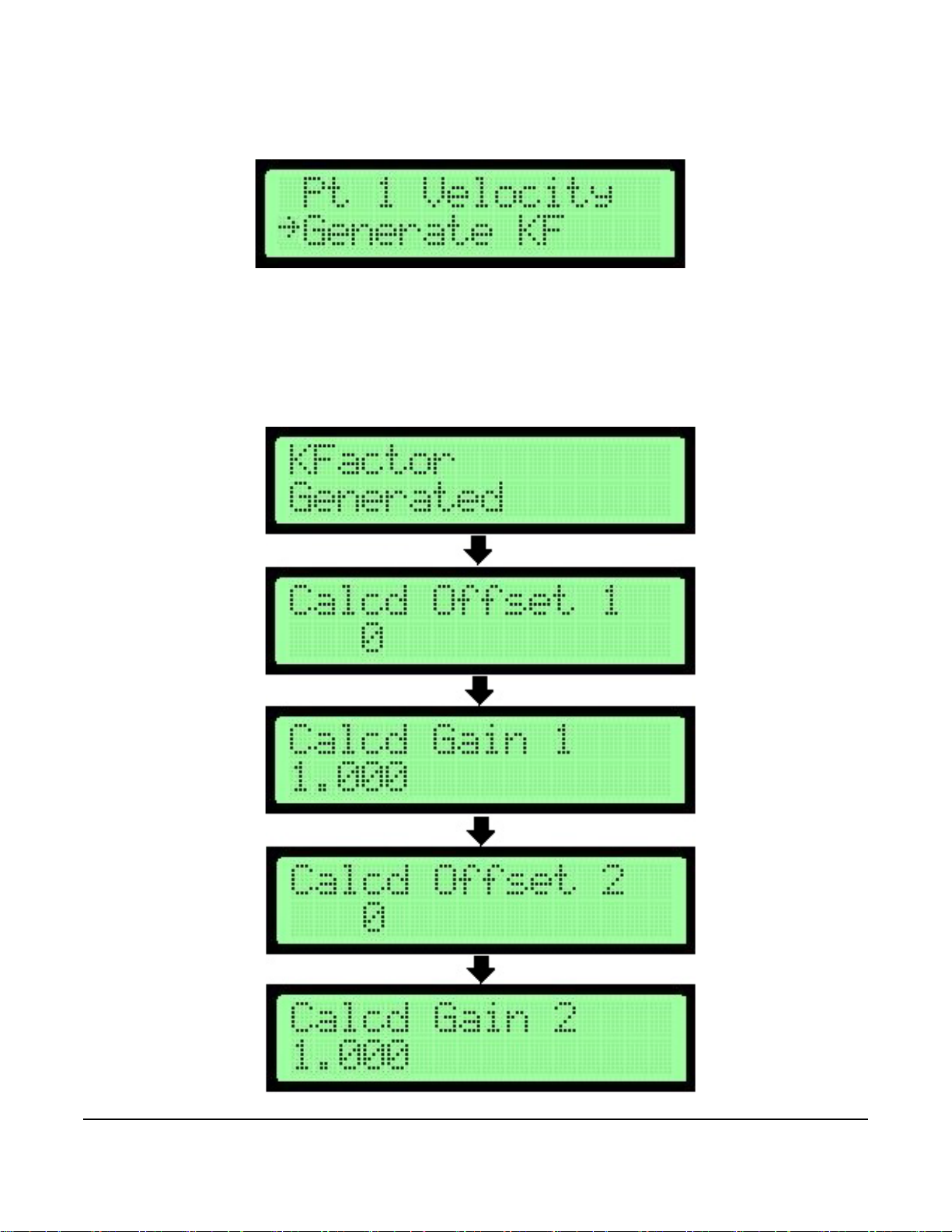
Note: The line above Generate K-Factor may display a different number depending on the number of data points
Figure 52: Generate KF Selection Screen
Figure 53: K-Factor Equation Value Generator Screens
selected.
11. Press ENTER to generate the K-Factor equation values.
Note: When one data point is selected, the display indicates the K-Factor Generated and Calculated Offset 1
screens. When two data points are selected, the display indicates the K-Factor Generated, Calculated
Offset 1, and Calculated Gain 1 screens. When three data points are selected, all five screens display.
.
AD-1272 Advanced Thermal Dispersion Probe Airflow Measuring System Technical Bulletin
29
Page 30

12. In the Operator Menu, press UP or DOWN to scroll to the K-Factor Configuration submenu.
Figure 54: K-Factor Configuration Selection Screen
Figure 55: Menu Timeout Flowchart
Menu Timeout
ENTER
ESC or ENTER
*Default values shown
Selected Submenu
Submenu Selection Display
Figure 56: Menu Timeout Selection Screen
13. Press ENTER.
14. Press UP or DOWN to scroll through the submenu options and make any necessary updates. See Table 12 for
a description of the K-Factor Configuration submenu selection options and their configurable options.
Menu Timeout
The Menu Timeout submenu is used to select a time in minutes after which the device backlight dims and the
device returns to normal operation mode if no activity is detected in the Operator Menu.
Table 13: Menu Timeout Submenu Selection and Configurable Option
Menu Timeout
Submenu
Selection
Menu Timeout Select from 0 to 30 minutes. A value of 0 indicates that the display never times out and the backlight is
Configurable Option
always on.
1. In the Operator Menu, press UP or DOWN to scroll to the Menu Timeout submenu.
2. Press ENTER.
3. Make any necessary updates to the submenu selection. See Table 13 for a description of the Menu Timeout
submenu selection option and its configurable option.
AD-1272 Advanced Thermal Dispersion Probe Airflow Measuring System Technical Bulletin
30
Page 31

BACnet Network Configuration
Figure 57: BACnet Configuration Flowchart
BACNet Instance
BACNet Network BACNet On/Off
UP
DOWN
ENTER
ENTER
ESC or ENTER
ESC
ENTER
ESC or ENTER
BACNet Address
ENTER
ESC or ENTER
UP DOWN
BACNet Max
Masters
ENTER
UP
DOWN
ESC or ENTER
BACNet Baud
Rate
ENTER
UP
DOWN
ESC or ENTER
Exit this Menu
UP
DOWN
ENTER
*Default values shown
UP
DOWN
Returns to
Operator Menu
Con iguration
f
Selected Submenu
Submenu Selecti ons
Submenu Selection Display
F
I
G
:
f
l
o
w
c
h
a
r
t
_
b
a
c
n
e
t
_
n
e
t
w
o
r
k
The BACnet Network Configuration submenu turns BACnet on or off and configures parameters based on the
BACnet type.
Table 14: BACnet Network Configuration Submenu Selections and Configurable Options
BACnet Network
Configuration
Submenu
Selections
BACnet On/Off Select On or Off.
BACnet Instance Update the currently selected value. The instance number must be unique from all BACnet devices on
BACnet Address Select a value between 4 and 127. Holding down the button increases the rate the value updates.
BACnet Max Mast Select a value between 1 and 127. Holding down the button increases the rate the value updates.
BACnet Baud Rate Select the 9,600, 19,200, 38,400 (default), or 76,800 baud rate.
Configurable Options
the entire system. The range of values is 1 to 4,194,302.
AD-1272 Advanced Thermal Dispersion Probe Airflow Measuring System Technical Bulletin
31
Page 32

1. In the Operator Menu, press UP or DOWN to scroll to the BACnet Network Configuration submenu.
Figure 58: BACnet Network Configuration Selection Screen
2. Press ENTER.
3. Scroll through the submenu options and make any necessary updates. See Table 14 for a description of the
BACnet Network Configuration submenu selection options and their configurable options.
Note: If any changes are made to the BACnet Network Configuration parameters after turning on BACnet, you
must change the BACnet On/Off setting off and back on again to get the changes to take effect.
BACnet Objects
If BACnet communications is enabled on the AD-1272 and all parameters are correctly set (see Figure 57) the
BACnet objects listed below will be available to the Building Automation System (BAS). The units for the BACnet
objects will be the same as the units the display is configured for. For example, if the display is setup to show flow
on CFM, the units for the BACnet Flow objects will also be in CFM. The Flow and Temperature alarms must be
enabled in the AD-1272 (see Figure 59 through Figure 61) for the points to be map able to the BAS.
•Flow
• Temperature
• Low Flow Alarm (if enabled)
• High Flow Alarm (if enabled)
• Low Temperature Flow (if enabled)
• High Temperature Flow (if enabled)
Hardware Objects
If the Analog Outputs on the AD-1272 are wired directly to a field controller on the BAS it is important to note that
the high and low values for the Flow Output are configured in Feet per Minute (FPM) and the Temperature high and
low values are in Deg F when imperial units are selected and Meters per Second (MPS) with Deg C when SI units
are selected. If there is a need to convert the BAS to a different unit, calculate the corresponding values for the
units of measure and program the input’s high and low values with the calculated values. For example, if you have
a 24 x 24 in. (4 square feet) duct and the High Flow Output in the transmitter is set to 5000 FPM (default), the
corresponding high CFM value will be 20,000 CFM, see equation below.
[(24 in. x 24 in.)/144 square inches per square foot] x 5000 FPM = 20,000 CFM
The scaling for the input receiving the signal should be configured from 0 to 20,000 CFM.
AD-1272 Advanced Thermal Dispersion Probe Airflow Measuring System Technical Bulletin
32
Page 33

BACnet Flow Alarm Configuration
Figure 59: BACnet Flow Alarm Configuration Flowchart
UP
DOWN
Alarm High On/Off
BACNet Flow Alarm
Alarm Low On/Off
UP
DOWN
ENTER
ENTER
ESC or ENTER
ESC
ENTER
ESC or ENTER
Alarm Low
Setpoint
ENTER
ESC or ENTER
UP DOWN
Alarm High
Setpoint
ENTER
UP
DOWN
ESC or ENTER
Alarm Deadband
ENTER
ESC or ENTER
Alarm Delay
ENTER
UP
DOWN
ESC
*Default values shown
UP
DOWN
Exit this Menu
ENTER
DOWN
UP
Returns to
Operator Menu
Selected Submenu
Submenu Selec tions
Submenu Selection Display
F
I
G
:
f
l
o
w
c
h
a
r
t
_
b
a
c
n
e
t
_
?
o
w
The BACnet Flow Alarm Configuration submenu is only available when BACnet is on (see BACnet Network
Configuration). Alarm parameters can be configured including high and low alarms, setpoints, and alarm delay.
Table 15: BACnet Flow Alarm Configuration Submenu Selection and Configurable Options
BACnet Flow Alarm
Configuration
Submenu Selections
Alarm Low On/Off Select On or Off.
Alarm High On/Off Select On or Off.
Alarm Low Setpoint Choose a value the flow must go below for an alarm condition to exist.
Alarm High Setpoint Choose a value the flow must surpass for an alarm condition to exist.
Alarm Deadband
Setpoint
Alarm Delay Select the amount of time between any alarm condition and the BACnet Flow Alarm Low and High
Configurable Options
Choose a value of flow the controller must reach above the Alarm Low Setpoint for Alarm Low or
below the Alarm High Setpoint for Alarm High before an activated alarm resets. The display units
are the same as those chosen in the Display Configuration
activation. This value is adjustable between 0 and 10 minutes.
submenu and flow configuration.
AD-1272 Advanced Thermal Dispersion Probe Airflow Measuring System Technical Bulletin
33
Page 34

1. In the Operator Menu, press UP or DOWN to scroll to the BACnet Flow Alarm Configuration submenu.
Figure 60: BACnet Flow Alarm Configuration Selection Screen
2. Press ENTER.
3. Scroll through the submenu options and make any necessary updates. See Table 15 for a description of the
BACnet Flow Alarm Configuration submenu selection options and their configurable options.
AD-1272 Advanced Thermal Dispersion Probe Airflow Measuring System Technical Bulletin
34
Page 35

BACnet Temperature Alarm Configuration
Figure 61: BACnet Temperature Alarm Configuration Flowchart
UP
DOWN
Alarm High On/Off
BACNet Temperature
Alarm Low On/Off
UP
DOWN
ENTER
ENTER
ESC or ENTER
ESC
ENTER
ESC or ENTER
Alarm Low
Setpoint
ENTER
ESC or ENTER
UP DOWN
Alarm High
Setpoint
ENTER
UP
DOWN
ESC or ENTER
Alarm Deadband
ENTER
ESC or ENTER
Alarm Delay
ENTER
UP
DOWN
ESC
*Default values shown
UP
DOWN
Exit this Menu
ENTER
DOWN
UP
Returns to
Operator Menu
Selected Submenu
Submenu Selec tions
Submenu Selection Display
F
I
G
:
f
l
o
w
c
h
a
r
t
_
b
a
c
n
e
t
_
t
e
m
p
Alarm
The BACnet Temperature Alarm Configuration submenu is only available when BACnet is on (see BACnet Network
Configuration). In this submenu, you can configure temperature parameters including high and low alarms,
setpoints, and alarm delay.
Table 16: BACnet Temperature Alarm Configuration Submenu Selections and Configurable Options (Part 1
of 2)
BACnet Temperature
Alarm Configuration
Submenu Selections
Alarm Low On/Off Select On or Off.
Alarm High On/Off Select On or Off.
Alarm Low Setpoint Choose a value the temperature must go below for an alarm condition to exist.
Alarm High Setpoint Choose a value the temperature must surpass for an alarm condition to exist.
Configurable Options
AD-1272 Advanced Thermal Dispersion Probe Airflow Measuring System Technical Bulletin
35
Page 36

Table 16: BACnet Temperature Alarm Configuration Submenu Selections and Configurable Options (Part 2
Figure 62: BACnet Temperature Alarm Configuration Selection Menu
of 2)
BACnet Temperature
Alarm Configuration
Submenu Selections
Alarm Deadband
Setpoint
Alarm Delay Select the amount of time between any alarm condition and the BACnet Temperature Alarm Low
Configurable Options
Choose a value of temperature the controller must reach above the Alarm Low Setpoint for Alarm
Low or below the Alarm High Setpoint for Alarm High before an activated alarm resets. The
display units are the same as those chosen in the Display Configuration
and High activation. This value is adjustable between 0 and 10 minutes.
submenu.
1. In the Operator Menu, press UP or DOWN to scroll to the BACnet Temperature Alarm Configuration submenu.
2. Press ENTER.
3. Scroll through the submenu options and make any necessary updates. See Table 16 for a description of the
BACnet Temperature Alarm Configuration submenu selection options and their configurable options.
AD-1272 Advanced Thermal Dispersion Probe Airflow Measuring System Technical Bulletin
36
Page 37

Navigating the Supervisor Menu
Figure 63: Supervisor Menu Selection Screen
Figure 64: Supervisor PIN Selection Screen
The Supervisor Menu is used to enable or disable probes and individual sensors, scan all sensors for status
updates, and perform diagnostics on alert conditions. It is also used to restore the device to a pre-installation state.
1. When the AD-1272 Airflow Measuring System’s LCD screen displays the average temperature and average
velocity or volume, press MENU and UP or DOWN until the arrow is next to the Supervisor Menu.
2. Press ENTER to access the Supervisor Menu settings.
a. If the Supervisor PIN is enabled, the LCD screen displays the following message.
(1) Enter the 4-digit PIN to access the Supervisor Menu. PIN entry is made one digit at a time beginning
with the leftmost digit. Press UP or DOWN to scroll through the numbers 0 through 9.
(2) When the correct number is displayed, press ENTER to select the digit. The cursor automatically
moves to the next position. If an error is made after pressing ENTER, press ESC to go back and
change the digit.
Note: If the PIN is not correctly entered, the display returns to normal operation.
b. If the Supervisor PIN is not enabled, the Supervisor Menu selections display.
Note: See Enable, Disable, and Change the Supervisor PIN
for more information about enabling the PIN.
3. Press UP or DOWN to scroll through the available menu selections. See Table 17 for a list of Supervisor Menu
selections and their descriptions.
Note: Use any Supervisor Menu to access configurable options.
Table 17: Supervisor Menu Submenus (Part 1 of 2)
Supervisor Menu
Description
Submenus (Actual
Display Name)
Enable Supervisor PIN
(Enable Supv PIN)
Change Supervisor PIN
(Change Supv PIN)
Sensor Management
(Sensor Mgmt)
Reset Sensors
(Reset Sensors)
When enabled, prevents unauthorized access to the Supervisor Menu.
Set or change the Supervisor Menu PIN.
Scans the probe network for active and enabled sensors and enables or disables individual
sensors. It also displays the probe status and each sensor’s velocity and temperature
reading.
Allows the cycle of power to the sensors.
AD-1272 Advanced Thermal Dispersion Probe Airflow Measuring System Technical Bulletin
37
Page 38

Table 17: Supervisor Menu Submenus (Part 2 of 2)
Figure 65: Supervisor PIN Flowchart
Selected Submenu
*Default value s s hown
Normal Disp lay
Enable Supervisor
PIN
Change Supervisor
PIN
MENU
ENTER
ESC or ENTER
ENTER
ESC or ENTER
DOWN
UP
Submenu Selection Display
Supervisor Menu
Description
Submenus (Actual
Display Name)
Factory Default
(Factory Default)
Exit Supervisor Menu
(Exit Supv Menu)
Restores the device to the factory-default settings. Any previous settings made in the
Operator and Supervisor Menus are reset including dimensions, the Operator PIN, and
custom text.
Returns the display to normal operation.
Enable, Disable, and Change the Supervisor PIN
The Enable Supervisor PIN and Change Supervisor PIN menu options are used to enable or disable the
Supervisor Menu PIN and change the current PIN.
Note: The PIN is not set or enabled on a device with factory-default settings.
Note: If the Enable Supervisor PIN option is selected, the Supervisor Menu can only be accessed with a PIN.
To enable or disable the PIN:
1. Enter the Enable Supervisor PIN submenu.
2. Press UP or DOWN to choose Yes to enable the PIN or No to disable the PIN.
3. Press ENTER to confirm the selection.
To update the PIN:
1. Enter the Change Supervisor PIN submenu.
2. Press UP or DOWN to scroll to display the numbers 0 through 9.
3. When the correct number is displayed, press ENTER to select the digit. The cursor automatically moves to the
4. Enter the last digit and press ENTER to store the PIN number. The display returns to the Supervisor Menu
next position. If an error is made after pressing ENTER, press ESC to return to the previous digit.
submenu display. Alternatively, press ESC to return to the Supervisor Menu without updating the PIN.
Note: If the PIN settings are enabled, the PIN number must be entered each time the Supervisor Menu is
entered.
AD-1272 Advanced Thermal Dispersion Probe Airflow Measuring System Technical Bulletin
38
Page 39

Sensor Management
Figure 66: Sensor Management Flowchart
UP
DOWN
Scan for Sensors
Sensor
Management
UP
DOWN
ENTER
ENTER
ESC or ENTER
ESC
ENTER
Display Sensor
Status
ENTER
ESC
UP
DOWN
Enable Sensors
ENTER
UP DOWN
ESC
Disable Sensors
ENTER
ESC
Display Probe
Status
ENTER
UP
DOWN
ESC
*Default values shown
UP
DOWN
Display Probe
Data
ENTER
ESC
Exit this Menu
UP
DOWN
ENTER
DOWN
Display Active
Sensors
UP
Selected Submenu
Submenu Selections
Submenu Selection Display
F
I
G
:
f
l
o
w
c
h
a
r
t
_
s
e
n
s
o
r
_
m
g
m
t
Returns to
Operator Menu
The Sensor Management submenu is used to scan the sensor network for active sensors and enable or disable
individual sensors. This also displays each sensor’s velocity and temperature reading.
Probes are numbered with P=Primary, 0=First Achillary, 1=Second Anchillary, and so on. Sensor information is
displayed on the left-most sensor in the enclosure at the end of the probe.
Note: When the Primary Transmitter with Display is located remotely the AD-1272 count the Primary Transmitter
as an additional probe. This will cause the number of probes to be shown as one greater than the number
of ancillary probes.
AD-1272 Advanced Thermal Dispersion Probe Airflow Measuring System Technical Bulletin
39
Page 40

Table 18: Sensor Management Submenu Selections and Configurable Options or Display Screens
Figure 67: Sensor Management Selection Screen
Figure 68: Display Active Sensor Selection Screen
Figure 69: Probe and Sensor Display Screen
Sensor
Management
Submenu
Selections
Display Active
Sensor
Scan for Sensor Scan for sensors and restart all devices on the network. The primary probe restarts last. After
Display Sensor
Status
Enable Sensors
Disable Sensors
Display Probe
Status
Display Probe Data
1. The primary probe (P) is displayed first. Ancillary probes use hexadecimal (base 16) numbering. The hexadecimal number
corresponds to the setting on the probe’s rotary switch.
Configurable Options or Display Screen
Display screen indicates the number of active and total probes and sensors.
restarting, the primary probe returns to normal operation.
1
Select the probe addresses on the probe network (P, 0 through F)
indicates a disabled address.
1
Select between probes (P, 0 through F)
(1 through 8) to enable.
Select between probes (P, 0 through F)
(1 through 8) to disable.
Select between probes (P, 0 through F)
the probe’s average temperature and velocity (FPM) from the probe data screen.
Select between probes (P, 0 through F)
sensors (1 through 8).
then select between sensors. Choose the sensor
1
then select between sensors. Choose the sensor
1
to choose the probe on line 2 of the screen. Display indicates
1
. Display shows the individual sensor data. Select between
. V indicates a valid address and D
1. In the Supervisor Menu, press UP or DOWN to scroll to the Sensor Management submenu. Press ENTER.
2. Press UP or DOWN to scroll to Display Active Sensor.
3. Press ENTER. The display indicates the number of active probes and sensors. In this example, one probe is
active and enabled and two out of two sensors are valid and enabled.
AD-1272 Advanced Thermal Dispersion Probe Airflow Measuring System Technical Bulletin
40
Page 41

4. Press ESC or ENTER to return to the Sensor Management submenu.
Figure 70: Scan for Sensor Selection Screen
Figure 71: Scanning for Sensors Display Screen
Figure 72: Display Sensor Status Selection Screen
Figure 73: Sensor Status Display Screen
5. Press UP or DOWN to scroll to the Scan for Sensors submenu selection. Press ENTER. When this option is
selected, the primary probe sends scan and restart commands to all ancillary probes on the wired probe
network. The primary probe then restarts to detect all probes and sensors and updates the inventory.
6. Press ENTER to scan for sensors.The primary probe provides scan and restart commands to the network.
7. Once the scan is complete, the display returns to the normal operation mode. Press MENU.
8. Press UP or DOWN to scroll to the Supervisor Menu. Press ENTER.
9. Press UP or DOWN to scroll to the Display Sensor Status submenu.
10. Press ENTER. The display indicates the following message:
11. Press UP or DOWN to scroll to the probe to display on line 1 of the display.
12. Press ESC. The display returns to the Sensor Management submenu.
AD-1272 Advanced Thermal Dispersion Probe Airflow Measuring System Technical Bulletin
41
Page 42

13. Press UP or DOWN to scroll to the Enable Sensors submenu selection. Press ENTER.
Figure 74: Enable Sensors Selection Screen
Figure 75: Probe Selection Display Screen
Figure 76: Probe Selection Display Screen
Figure 77: Disable Sensors Selection Screen
Figure 78: Disable Probe Status Selection Screen
14. Scroll to display the correct probe number on line 2 and press ENTER.
15. Press UP or DOWN to display the sensor numbers that are enabled by selecting this option and press ENTER.
16. Press ESC. The display returns to the Sensor Management submenu.
17. Scroll to the Disable Sensors submenu selection and press ENTER.
18. Follow Steps 14 and 15 to disable the sensors.
19. Press UP or DOWN to scroll to the Display Probe Status submenu selection.
AD-1272 Advanced Thermal Dispersion Probe Airflow Measuring System Technical Bulletin
42
Page 43
20. Press ENTER. The display indicates:
Figure 79: Active Sensors Display Screen
Figure 80: Probe Data Display Screen
Figure 81: Individual Sensor Information Screen
21. Press UP or DOWN to scroll to the probe that are displayed on line 1 of the display with this selection. Press
ENTER. The display shows the probe data.
22. Press ENTER to view the status and values of individual sensors on the selected probe. Press UP or DOWN to
scroll through the sensors (1 through 8). Press ESC to return to the Probe Data screen.
23. Press UP or DOWN to scroll the menu display to the remaining probes, or press ESC to return to the Sensor
Management menu.
Note: In the Sensor Management submenu, press UP or DOWN to scroll to the Display Probe Data submenu
selection and press ENTER to display the probe data without going through the Probe Status submenu
selection.
24. Press UP or DOWN to scroll to Exit this Menu and press ENTER to return to the Supervisor Menu.
AD-1272 Advanced Thermal Dispersion Probe Airflow Measuring System Technical Bulletin
43
Page 44
Reset Sensor Network
Figure 82: Rese t Sen s or Net w ork Flowc h a rt
Reset Sensors
*Default values shown
Selected Submenu
Submenu Display
F
I
G
:
f
l
o
w
c
h
a
r
t
_
r
e
s
e
t
ENTER
Figure 83: Reset Sensors Selection Screen
The Reset Sensor Network submenu is used to reset all the sensors on the network and cycle power to the devices
for an inventory. It also re-enables any disabled probes or sensors on the network
Table 19: Reset Sensor Network Submenu Selections and Display Screens
Reset Sensor
Network Submenu
Selection
Reset Sensors Primary probe commands all probes to re enable all sensors and to restart. Primary probe performs a
Display Screens
sensor scan and re-enables sensors to get an inventory from the probe network. Primary probe
returns to normal operation.
.
1. In the Supervisor Menu, press UP or DOWN to scroll to the Reset Sensors submenu.
AD-1272 Advanced Thermal Dispersion Probe Airflow Measuring System Technical Bulletin
44
Page 45

2. Press ENTER. The display appears as follows:
Figure 84: Enable Probes Display Screens
The primary probe automatically resets all the sensors and devices and then restarts. After warming up, the
primary probe returns to the normal operation mode.
AD-1272 Advanced Thermal Dispersion Probe Airflow Measuring System Technical Bulletin
45
Page 46

Factory Default Reset
Figure 85: Factory Default Reset Flowchart
Factory Default
*Default values shown
Selected Submenu
Submenu Display
F
I
G
:
f
l
o
w
c
h
a
r
t
_
d
e
f
a
u
l
t
ENTER
Figure 86: Factory Default Selection Screen
The Factory Default Reset submenu is used to reset all settings to the original factory-default settings.
Note: After a Factory Default Reset, any unique configuration settings must be re-entered if they are different
from the default settings
.
Table 20: Factory Default Reset Submenu Selection and Display Screens
Factory Default
Reset Submenu
Selection
Factory Default Cycle power from probe to re-enable all sensors and restart the auxiliary devices.
1. In the Supervisor Menu, press UP or DOWN to scroll to the Factory Default submenu.
Actions and Display Screens
Perform a local sensor scan and re-enable local sensors to get an inventory from the probe network.
Display returns to normal operation and factory-default settings are restored.
AD-1272 Advanced Thermal Dispersion Probe Airflow Measuring System Technical Bulletin
46
Page 47

2. Press ENTER. The display indicates:
Figure 87: Enable Probes Display Screens
The primary probe automatically resets all the sensors and devices and then restarts. After warming up, it
returns to the normal operation mode. All settings are restored to their factory-default state.
Troubleshooting
Use Table 21 to troubleshoot problems with the AD-1272 Airflow Measuring System.
Table 21: AD-1272 System Troubleshooting (Part 1 of 2)
Problem Possible Cause Corrective Action
Airflow readings do not match what
T&B is reporting
Turbulent or non-uniform airflow across
the air measurement station.
Use Automatic K-factor Configuration
and use 1 point calibration if only gain is
required. If flow is non-linear use two or
three-point calibration feature.
Install additional probes to provide more
sensing points.
Move probes to a better location in
accordance with the minimum
placement guide.
Check for leaks in the duct.
AD-1272 Advanced Thermal Dispersion Probe Airflow Measuring System Technical Bulletin
47
Page 48

Table 21: AD-1272 System Troubleshooting (Part 2 of 2)
Problem Possible Cause Corrective Action
No display No power Verify 24 VAC power at power terminal.
Make sure the ribbon cable is fully
seated in the board’s socket.
Visually check to make sure membrane
is plugged in to the display board in lid.
Incorrect number of PROBES shown
when the power is applied.
No BACnet communication with the
BAS
Probe network is not wired correctly or
the plug is plugged into the wrong port.
Duplicate addresses on Probe Network Verify each ancillary probe has a unique
Network wires terminated to the
incorrect point or the wrong connector.
The device is not configured properly. Verify configuration parameters in the
Verify wiring using the probe network
wiring information in the AD-1272
Thermal Dispersion Probe Airflow
Measuring Station Installation
Instructions (LIT-12012552).
Look at the drawings and make sure
the left and the right terminals are not
swapped. AO, Probe Network and
BACnet ports on the primary fit into any
of the plugs so make sure connections
are correct on the board.
address by checking the rotary dial
position.
Verify wiring using the BACnet wiring
information in the AD-1272 Thermal
Dispersion Probe Airflow Measuring
Station Installation Instructions (LIT-
12012552).
Look at the drawings and make sure
the left and right terminals are not
swapped.
BACnet Network Configuration settings
match what is required to communicate
with the BAS.
AD-1272 Advanced Thermal Dispersion Probe Airflow Measuring System Technical Bulletin
48
 Loading...