

Page 1
Controls Group 507 E. Michigan Street
P.O. Box 423, Milwaukee, WI 53202
$äì6 SâZ мдлжмжн дWKFFгжркм 5HIULJHUDWLRQ 7HPSHUDWXUHý&RQWUROV 5HYã
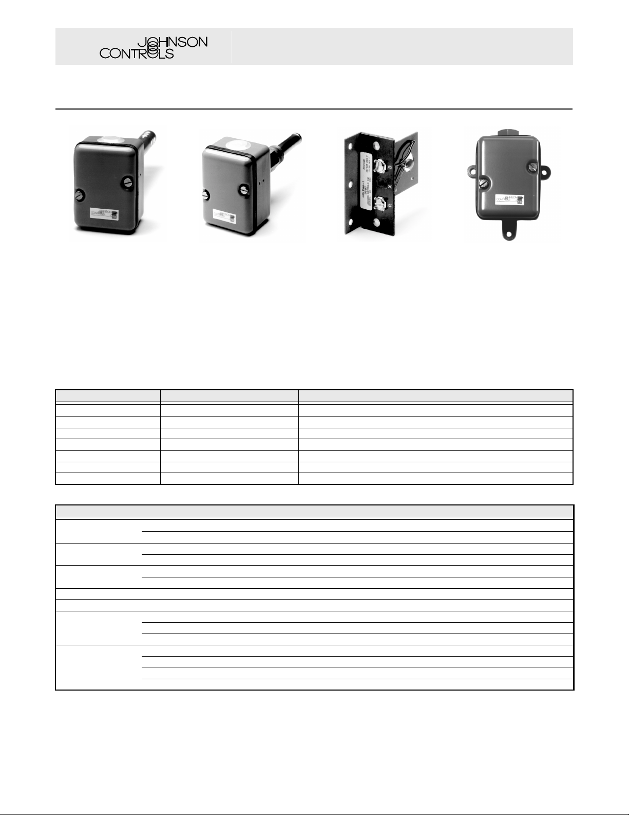
A91 Series
Thermistor Temperature Sensor
DäìJDDìFïWLIý
DäìDDDìíïWLIý
DäìSDDìFïWLIý
Code No. Lit-1927170
DäìQDDìFïWLIý
нжомеодж
ORJRг
-&,
OHIWýIWã
UHIULJ
ULJKWýIWã
VWDQGDUG
6HFWúý ýæ
VH4úý ýêè
A91GAA Duct Sensor with
Enclosure
Description
These thermistor sensors are for
use with Johnson Controls Series
R81Q and R93 controllers to
operate Series M100 actuators
and R353 series sequencing
A91AAA Immersion Sensor
Features
• high sensitivity
• fast response
• easy to install and wire
A91PAA Duct Sensor Less
Enclosure
Applications
The sensors are designed for a
wide range of applications
including space, outdoor,
immersion, and duct temperature
sensing.
modules.
Selection Chart
Code Number Temperature Range °F (°C) Description
A91AAA-10C 40 to 90°F (4 to 32) Immersion sensor
A91AAA-11C 60 to 120°F (15 to 50) Immersion sensor
A91GAA-1C 60 to 120°F (15 to 50) Duct sensor with enclosure
A91GAA-2C 40 to 90°F (4 to 32) Duct sensor with enclosure
A91NAA-3C 40 to 90°F (4 to 32) Outdoor sensor with enclosure
A91PAA-1C 60 to 120°F (15 to 50) Duct sensor less enclosure
A91PAA-2C 40 to 90°F (4 to 32) Duct sensor less enclosure
Specifications
A91 Series Thermistor Temperature Sensors
Ambient
Temperatures
Conduit
Openings
Element
Insertion Depth
Operating Ranges 40 to 90°F (5 to 30°C), 60 to 120°F (15 to 50°C)
Wiring Connections Screw type terminals
Material
Mounting
Minimum -40°F (-40°C)
Maximum 140°F (60°C)
A91AAA, A91GAA Two 7/8 in. (22 mm) diameter holes for 1/2 in. conduit
A91NAA One 1/2 in. conduit hub
A91AAA 2 7/16 in. (62 mm)
A91GAA 7 3/4 in. (197 mm)
Enclosure 0.062 in. (1.6 mm) cold rolled steel
Tube A91AAA–thin copper with soft solder A91GAA–thin aluminum
Connector A91AAA – 2 1/4 in. (57 mm) extention,1 1/16 in. (27 mm) hex brass with 3/4 in. NPT threads
$äì$$$ 3/4 in. NPT connector
$äì*$$ Two holes in back of case
$äì1$$ Three mounting lugs or conduit connector
$äì3$$ Two holes in bracket
A91NAA Outdoor Sensor
To Order
Specify the code number from the
following selection chart.
The performance specifications are nominal and conform to acceptable industry standards. For applications at conditions beyond these specifications, consult the local Johnson
Controls office. Johnson Controls, Inc. shall not be liable for damages resulting from misapplication or misuse of its products.
1/2
© 02/99 Johnson Controls, Inc
Page 2
Controls Group 507 E. Michigan Street
3100
3000
2900
2800
2700
2600
2500
2400
2300
2200
2100
2000
1900
1800
1700
1600
1500
1400
1300
1200
1100
1000
900
800
700
600
500
400
300
200
10 0 1020304050 60
0
20 40 60 80 100 120 140 160 F
70 C
Temperatur e
Resistance In Ohms
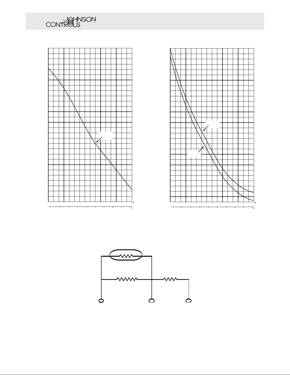
Terminals
"R" to "B"
Terminals
"R" to "X"
P.O. Box 423, Milwaukee, WI 53202
Code No. Lit-1927170
A91 Series Thermistor Temperature Sensor (Continued)
WHPSçíïHSVý
3100
3000
2900
2800
2700
2600
2500
2400
2300
2200
2100
2000
1900
1800
1700
1600
1500
1400
1300
Resistance In Ohms
1200
1100
1000
900
800
700
600
500
400
300
WKHUPLVWïHSVý
The performance specifications are nominal and conform to acceptable industry standards. For applications at conditions beyond these specifications, consult the local Johnson
Controls office. Johnson Controls, Inc. shall not be liable for damages resulting from misapplication or misuse of its products.
200
20 40 60 80 100 120 140 160 F
0
10 0 1020304050 60
Temperatur e
Temperature-Resistance Curve for 60 to 120°F (15 to 50°C)
Range
Terminals “R” and “B” Are Used For 40 to 90°F Range With Integral Set point at Controller.
Terminals “R” and “X” Are Used on Applic a ti ons Requiring Remote Set point.
Termina ls
"R" to "B"
70 C
Therm i st o r
R
WHPSéíïHSVý
Temperature-Resistance Curve for 40 to 90°F (5 to 30°C) Range
and 15 to 50°F (-9 to 10°C) Range
140
X
2/2
B
© 02/99 Johnson Controls, Inc
 Loading...