

Page 1
A70 Series
Line 2
Line 1
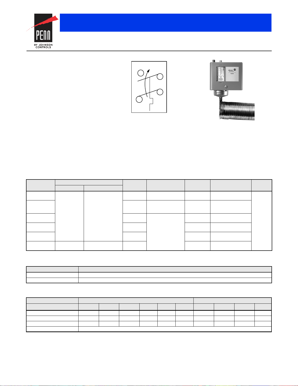
M1
M2
Action on Increase
on Temperature
a70s.eps
A70 Series Action Diagram
A70GA-1 Temperature Control
Single-Stage Electromechanical Temperature Controls
Code No. LIT-1927140
A70 Series Four-Wire, Two-Circuit Temperature Control
Description
The A70 Series Temperature Control
incorporates a vapor-charged sensing
element. The A70G, A70H, and A70K have a
four-wire, two-circuit contact block that
contains two isolated sets of contacts.
The contacts are designed so that when the
main contact opens, the auxiliary contact
closes.
Refer to the A70, A72 Series Temperature
Controls for Refrigeration and Heating
Product Bulletin (LIT-125155) for important
product application information.
Features
• long-life, snap-acting contacts
• automatic or manual reset models
Applications
Typical applications include energizing an
indicator light after a low temperature cutout on
a ventilating system.
Selection Charts
A70 Series Four-Wire, Two-Circuit Temperature Control
Product Code
Number
A70GA-1C
A70GA-2C 35 to 80
A70HA-1C
A70HA-2C 35 to 80
A70HA-14C 15 to 55
A70KA-1C Open high Close high 100 to 170
1. On these models, the low cutout stop is set and sealed at 35°F (1.6°C). It cannot be set lower. The control responds only to the lowest temperature
along any 14 to 16 in. section of the entire 20 ft element.
Main Contacts Auxiliary Contacts
1
1
Open low Close low
Replacement Covers
Product Code Number Description
CVR17A-620R Automatic reset cover
CVR17A-621R Manual reset cover
Switch Action Range
°F (°C)
15 to 55
(-9.4 to 12.8)
(1.7 to 26.7)
15 to 55
(-9.4 to 12.8)
(1.7 to 26.7)
(-9.4 to 12.8)
(37.8 to 76.7)
Differential
F° (C°)
5 (2.8) 20 ft of 1/8 in.
3 to 30
(-16.1 to -1.1),
factory set at 12 (-11.1)
Manual reset
Bulb and
Capillary
O.D. tubing
3/8 in. x 3 in.
6 ft capillary
20 ft of 1/8 in.
O.D. tubing
3/8 in. x 3 in.
6 ft capillary
20 ft of 1/8 in.
O.D. tubing
3/8 in. x 3 in.
6 ft capillary
Maximum Bulb
Temperature °F (°C)
400 (204.4)
250 (121)
400 (204.4)
250 (121)
400 (204.4)
240 (116)
Range
Adjuster
Screwdriver
slot
Technical Specifications
Electrical Ratings
Pole Number LINE-M2 (Main) LINE-M1 (Auxiliary)
Motor Ratings VAC 120 208 240 277
AC Full Load A 16.0 9.2 8.0 — 5.0 4.8 6.0 3.4 3.0 —
AC Locked Rotor A 96.0 55.2 48.0 — 30.0 28.8 36.0 20.4 18.0 —
AC Non-Inductive A 16.0 9.2 8.0 7.2 — — 6.0 6.0 6.0 6.0
Pilot Duty – Both Poles 125 VA, 120 to 600 VAC and 57.5 VA, 120 to 300 VDC
1. Not compressor motor loads.
The performance specifications are nomina l and con form to accep table ind ustry stand ards. For applicati ons at con ditions be yond these specification s, consult th
Johnson Controls, Inc. shall not be liable for damages resulting from misapplication or misuse of its products. © 2015 Johnson Controls, Inc.
R-40
480
1
600
1
120 208 240 277
 Loading...