

Page 1
a36 IN.eps
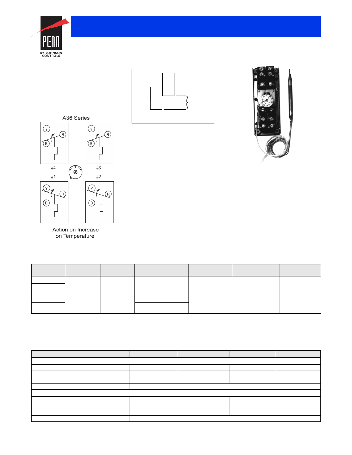
A36 Series Action Diagram
Switch
Differ en tial
Switch
Differential
Switch
Differential
Intersta ge
Differ ential
a36diff.eps
A36 Series Differential Diagram
A36AHA-52 Remote
Bulb Thermostat
Multi-Stage Electromechanical Temperature Controls
A36 Series Four-Stage Remote Bulb Thermostats
Description
The A36 series are four-stage thermostats
with open construction for use in panel
mounting.
Refer to the Type A36AHA 4-Stage Computer
Environmental Temperature Control Product
Bulletin (LIT-125145) for important product
application information.
Features
Screwdriver slot adjustment with calibrated
dial enables movement of entire staging band
within the range.
Applications
Use for cycling control for multiple
refrigeration compressors or unloading type
compressors.
Accessories
Order Enclosure CSE57A-600 separately, if
required.
Code No. LIT-1927135
Repair Information
If the A36 Series Four-Stage Remote Bulb
Thermostat fails to operate within its
specifications, replace the unit. For a
replacement thermostat, contact the nearest
Johnson
Controls®
representative.
Selection Chart
Product Code
Number
A36AHA-50C
A36AHA-52C
A36AHA-58C
A36AHB-33C
1. Calibrated at mid-switching point; computer room or comfort control.
2. Calibrated at low-switching point; special close control chiller applications.
Switch
Action
1
Four Single-Pole,
Double-Throw
1
(SPDT)
switches
2
1
Specifications
Maximum bulb temperature is 120°F (49°C) in operation and 140°F (60°C) when shipping.
Electrical Ratings (Per Switch)
Motor Ratings VAC 120 208 240 277
AC Full Load A 10.0 6.9 5.0 –
AC Locked Rotor A 60.0 41.4 30.0 –
Non-Inductive A 16.0 9.2 8.0 7.2
Pilot Duty 125 VA, 120 to 227 VAC
AC Full Load A 6.0 3.4 3.0 –
AC Locked Rotor A 36.0 20.4 18.0 –
Non-Inductive A 10.0 5.7 5.0 4.3
Pilot Duty 125 VA, 120 to 227 VAC
The performance specifications are nomina l and con form to accep table ind ustry stand ards. For applicati ons at con ditions be yond these specification s, consult th
Johnson Controls, Inc. shall not be liable for damages resulting from misapplication or misuse of its products. © 2015 Johnson Controls, Inc.
Range °F (°C) Differential F° (C°)
Fixed
55 to 95
(13 to 35)
0 to 70
(-18 to 21)
Two each stage
1 1/2 (0.8) between stages
Three each stage
2-1/2 (1.4) between stages
Two each stage
2-1/2 (1.4) between stages
A36AHA
A36AHB
R-65
Bulb and
Capillary
3/8 in. x 5-1/4 in.
18 in. capillary
w ith 12 in. nylon armor
3/8 in. x 4-3/4 in.
15 ft braid armor
capillary
Bulb Well No.
(Order Separately)
WEL14A-603R Screwdriver slot with
WEL14A-602R
Range
Adjuster
calibrated dial
 Loading...