

Page 1
A350R
Electronic Temperature Reset Control (with Relay)
Code No. LIT-1922535
Issued November 18, 2008
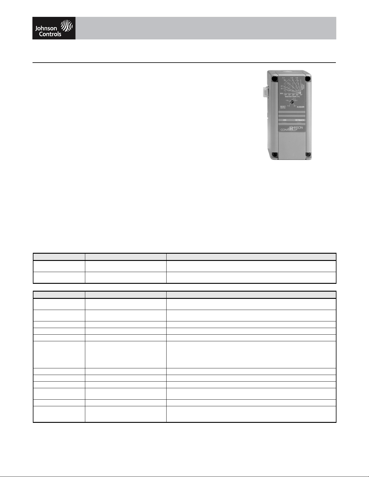
Description
The A350R Reset Controller is designed to
raise or lower the setpoint of supply water
temperature based upon a proportionate drop
or rise in temperature at the master (outdoor)
sensor. The co
ntrol output is a Single-Pole,
Single-Throw (SPST) normally open relay with
Light-Emitting Diode (LED) indication.
The adjustable differential enables the user to
match the amount of control (maximum to
minimum) required for a given application. An
adjustable reset ratio adapts to a variety of
weather zones and to the specific heat loss
characteristics of most buildings.
As with all System 350 products, the A350R is
housed in a NEMA 1, high-impact plastic
enclosure. The modular design provides easy,
plug-together connections for quick
installation and future expandability.
Features
• modular design enables stage, display,
and transformer modules to be purchased
and installed as necessary
• adjustable master reset setpoint (M.R.S.)
enables the user to select a master
(outdoor) sensor temperature starting point
for the supply reset ramp
• adjustable minimum and maximum supply
temperature permits compliance with
equipment manufacturer’s specifications
• selectable warm weather shutdown
temperature saves energy by disabling
equipment when the master sensor
temperature rises to a point where heating
is no longer required
• adjustable setback temperature saves
energy by lowering the supply temperature
setpoint at night or during unoccupied
periods
Applications
The A350R Temperature Reset Controller can
be used as a stand-alone device or in
conjunction with plug-together accessory
modules. The addition of the S350A or S350C
for on/off output, or an S350P for a
proportional or proportional plus integral
output allows this temperature system to
control a variety of single or multiple stage
Heating Ventilation Air Conditioning and
Refrigeration (HVAC/R) applications. Typical
applications include reset of single or
multistage boilers.
A350R
Selection Charts
Code Number Item Description
A350RS-1C A350R Temperature Reset Control Temperature Reset Control
A350RT-1C A350R Temperature Reset Control Temperature Reset Control
Accessories and Replacement Parts
Code Number Item Description
D350AA-1C
D350BA-1C
S350AA-1C
S350AB-1C
S350CC-1C Slave Stage Module Dual Scale (°F and °C)
S350PQ-1C Proportional Stage Module Dual Scale (°F and °C)
Y350R-1C Power Module 120/240 VAC, 50/60 Hz input; rectified 24V Class 2 output
A99BB-300C
A99BC-25C
A99BC-300C
A99BC-500C
A99BC-1500C
BOX10A-600R Enclosure PVC Sensor Enclosure
WEL11A-601R Immersion Well For liquid sensing applications
SHL10A-603R Sun Shield For use with outside sensors in sunny locations
BKT287-1R
BKT287-2R
PLT344-1R DIN Rail End Clamps Two end clamps
WHA29A-600R
WHA29A-603R
WHA29A-604R
1. WHA29A-600R can also be used to daisy chain S350 Stage Modules together.
Display Module Fahrenheit Scale
On-Off Stage Module Fahrenheit Scale
Temperature Sensors PTC Silicon Sensor with PVC Cable; Cable length 9-3/4 ft (3m)
DIN Rail Sections 35 x 7.5 mm, 12 in./0.305 m long
Cable for Remote Mounting
of D350 Display Module
(packaged with A99BB-300C and A99BC-25C sensors)
(temperature sensors not included)
Celsius Scale
Celsius Scale
PTC Silcon Sensor with high temp. silicon cable; cable length 9-3/4 in. (0.25 m)
PTC Silcon Sensor with high temp. silicon cable; cable length 9-3/4 ft (3 m)
PTC Silcon Sensor with high temp. silicon cable; cable length 16-3/8 ft (5 m)
PTC Silcon Sensor with high temp. silicon cable; cable length 49 ft (15 m)
35 x 7.5 mm, 36 in./0.914 m long
3 ft (0.9 m)
25 ft (7.6 m)
50 ft (15.2 m)
1
The performance specifications are nomina l and con form to accep table ind ustry stand ards. For applicati ons at con ditions be yond these specification s, consult the local Jo hnson Controls office.
Johnson Controls, Inc. shall not be liable for damages resulting from misapplication or misuse of its products. © 2008 Johnson Controls, Inc.
www.johnsoncontrols.com
1 of 2
Page 2
Electronic Temperature Reset Control (With Relay) (Continued)
Technical Specifications
A350R Electronic Temperature Reset Control
Supply Voltage
Power Consumption 3.2 VA maxi mum
Ambient Temperature Operating: -30 to 150°F (-34 to 66°C)
Humidity 0 to 95% RH non-condensing, 85°F (29°C) maximum dew point
Reset Ratio Adjustment Range 1:5 to 3:1 (master supply)
Reset Action Reverse acting
Master Reset Setpoint Adjustment Range 40 to 70°F (4 to 21°C)
Minimum Supply Temperature Adjustment Range 50 to 160°F (10 to 71°C)
Maximum Supply Temperature Adjustment Range 160 to 220°F (71 to 104°C)
Differential Adjustment Range 1 to 30F° (0.5 to 17C°)
Relay On-Time Jumper Selectable: OFF, 1 min., 2 min., or 3 min.
Warm Weather Shutdown Jumper Selectable: OFF, 60, 64, 68, or 72°F (OFF, 16, 18, 20, or 22°C)
Setback Adjustment Range 0 to 30F° (0 to 17C°)
Mode of Operation Heating (Differential is below the setpoint.)
Relay Contact SPST maximum: 4A non-inductive, 24 VAC; Pilot Duty 42.4 VA at 24 V AC
Case and Cover Material NEMA 1, high- impact thermoplastic
Agency Listing UL Guide No. XAPX and cUL Guide No. XAPX7, File E27734
1. Only one supply voltage source may be used.
1
Transformer: 20 to 30 VAC, Class 2, 50/60 Hz
Y350R: 120/240 VAC, 50/60 Hz
Shipping: -40 to 185°F (-40 to 85°C)
(Enabled by an external time clock)
minimum: 100 mA at 5 VDC
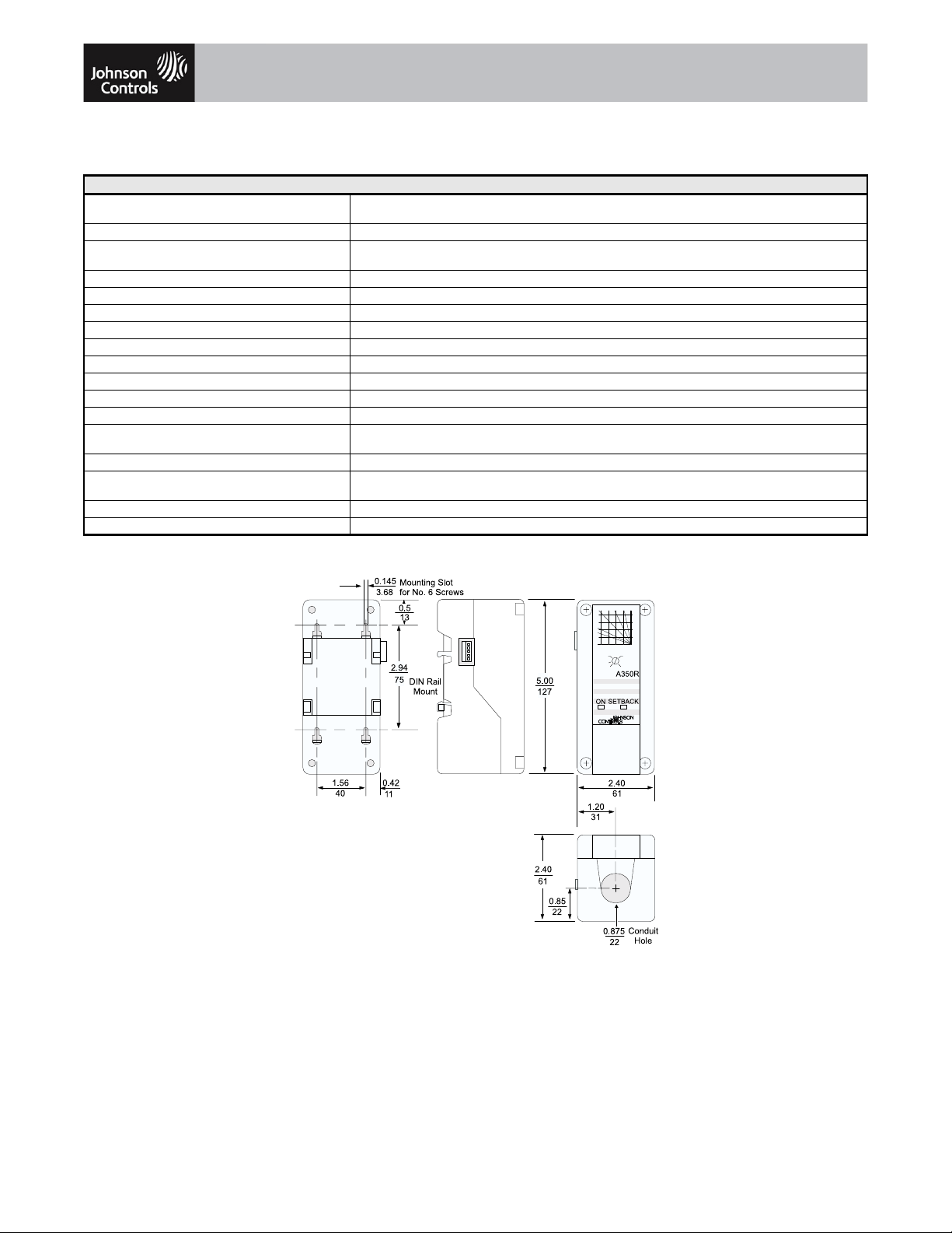
a350r2dim.eps
A350R Dimensions, in. (mm)
The performance specifications are no minal a nd conform t o accept able ind ustry stand ards. For app lication s at condi tions be yond these specifications, cons ult the local Johnso n Controls office.
Johnson Controls, Inc. shall not be liable for damages resulting from misapplication or misuse of its products. © 2008 Johnson Controls, Inc.
www.johnsoncontrols.com
2 of 2
 Loading...