

FANs 930, 930.5, 125, 121
Product/Technical Bulletin A350R
Issue Date April 8, 2014
System 350
A350R Electronic Temperature Reset Control (with Relay)
The A350R Electronic Temperature Reset Control is
designed to raise or lower the setpoint of supply water
temperature based upon a proportionate drop or rise
in temperature at the master (outdoor) sensor. The
control output is a Single-Pole, Single-Throw (SPST)
relay with Light-Emitting Diode (LED) relay status
indication.
The A350R’s differential may be adjusted for a given
application. An adjustable reset ratio adapts to a
variety of weather zones and to the specific heat loss
characteristics of most buildings.
TM
As are all System 350
housed in a NEMA 1, high-impact plastic enclosure.
The modular design provides easy, plug-together
connections for quick installation and future
expandability.
products, the A350R is
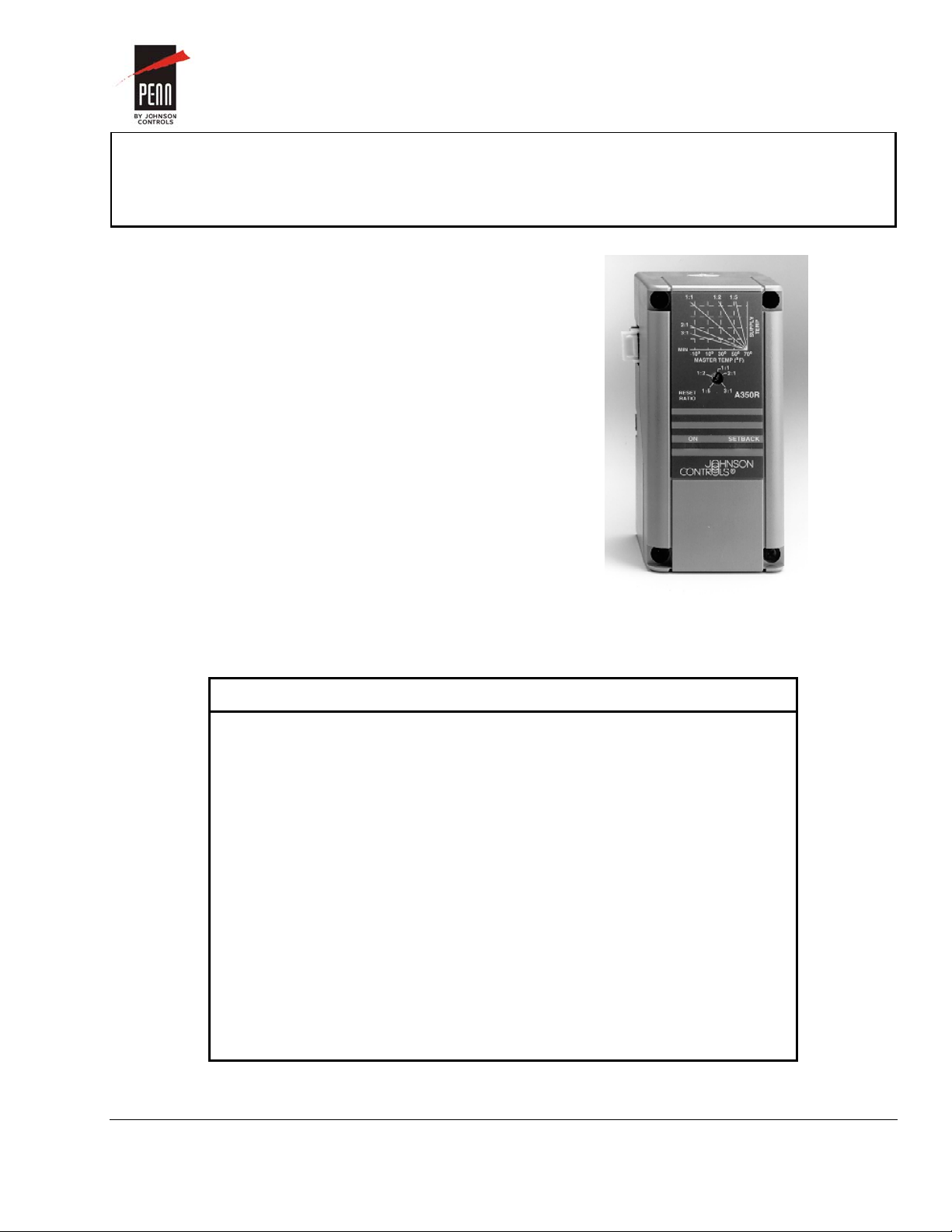
Figure 1: A350R Electronic Temperature
Reset Control
Features and Benefits
Modular Design Enables stage, display, and transformer
modules to be purchased and installed as
necessary
Adjustable Master Reset
Setpoint (M.R.S.)
Adjustable Minimum and
Maximum Supply
Temperature
Selectable Warm Weather
Shutdown Temperature
Adjustable Setback
Temperature
Enables the user to select a master (outdoor)
sensor temperature starting point for the
supply reset ramp
Permits compliance with equipment
manufacturer’s specifications
Saves energy by disabling equipment when
master sensor temperature rises to a point
where heating is no longer required
Saves energy by lowering the supply
temperature setpoint at night or during
unoccupied periods
© 2014 Johnson Controls, Inc. 1
Part No. 24-7664-1253, Rev. B www.johnsoncontrols.com
Code No. LIT-930033

pplication
A
The A350R Electronic Temperature Reset Control can
be used as a standalone device or in conjunction with
plug-together accessory modules. The addition of an
S350A or S350C for on/off output, or an S350P for a
proportional or proportional plus integral control,
allows this system to control a variety of single or
multiple stage Heating, Ventilation, and Air
Conditioning (HVAC) applications. Typical applications
include reset of single or multistage boilers.
peration
O
IMPORTANT: Use this A350R Electronic
Temperature Reset Control (with
Relay) only as an operating control.
Where failure or malfunction of the
reset module could lead to personal
injury or property damage to the
controlled equipment or other
property, additional precautions must
be designed into the control system.
Incorporate and maintain other
devices, such as supervisory or alarm
systems or safety or limit controls,
intended to warn of or protect against
failure or malfunction of the reset
module.
IMPORTANT: Utiliser ce A350R Electronic
Temperature Reset Control (with
Relay) uniquement en tant que
dispositif de contrôle de
fonctionnement. Lorsqu'une
défaillance ou un dysfonctionnement
du reset module risque de provoquer
des blessures ou d'endommager
l'équipement contrôlé ou un autre
équipement, la conception du système
de contrôle doit intégrer des dispositifs
de protection supplémentaires. Veiller
dans ce cas à intégrer de façon
permanente d'autres dispositifs, tels
que des systèmes de supervision ou
d'alarme, ou des dispositifs de
sécurité ou de limitation, ayant une
fonction d'avertissement ou de
protection en cas de défaillance ou de
dysfonctionnement du reset module.
The A350R operates on 24 VAC/VDC and provides a
Single-Pole, Single-Throw relay output. A front panel
LED lights to indicate the relay is energized. Features
include:
adjustable reset ratio
adjustable master reset setpoint
adjustable minimum and maximum supply
temperature
adjustable differential
selectable relay for Minimum ON Time
selectable warm weather shutdown temperature
adjustable setback temperature
Celsius Scale Conversion
As shipped from the factory, each A350R is installed
with the Fahrenheit temperature scale decal. A Celsius
temperature scale decal is provided under the cover of
the A350R. If the Celsius scale is desired, see the
Installation and Wiring section.
Reset Ratio Adjustment
Reset ratio is defined as the ratio of the change in
master sensor temperature to the change in supply
temperature setpoint. Example: For an application with
a reset ratio of 1:2, a one degree drop in master
sensor (for example, outdoor air) temperature causes
a two degree rise in the supply temperature setpoint.
Refer to Figure 2 for an example.
Reset ratio adjustment is made using the
potentiometer marked RESET RATIO. Refer to
Figure 4 for location.
Minimum Supply Temperature and Master
Reset Setpoint Adjustments
The minimum supply temperature and the master
reset setpoint adjustments determine the starting point
for the reset ramp. As the master (outdoor) sensor
temperature falls below the master reset setpoint, the
supply setpoint rises according to the reset ratio. As
the master sensor temperature rises above the master
reset setpoint, the supply setpoint will be maintained at
the minimum supply temperature. Refer to Figure 2 for
an example.
Minimum supply temperature adjustment is made
using the potentiometer marked MIN SUPPLY, and
master reset setpoint adjustment is made using the
potentiometer marked M.R.S. Refer to Figure 4 for
locations.
2 System 350 A350R Electronic Temperature Reset Control (with Relay) Product/Technical Bulletin

Maximum Supply Temperature
Adjustment
The maximum supply adjustment determines an end
point for the reset ramp. Refer to Figure 2 for an
example.
As the master sensor temperature drops below the
master reset setpoint, the supply setpoint temperature
rises according to the reset ratio. Upon further
reduction in master sensor temperature, the supply
setpoint temperature continues to rise until it reaches
the maximum supply temperature setpoint. The supply
temperature is maintained at the maximum supply
temperature setpoint even on a further decrease in
master sensor temperature. Use the formula found in
Adjustments section to determine the reset ratio.
Maximum supply temperature adjustment is made
using the potentiometer marked MAX SUPPLY.
Refer to Figure 4 for location.
Supply T emperature
Setpoint (°F)
200
T =20
D
Maximum Supply
Tempe r at ur e = 200
OFF
160
155
150
(Relay de-energized)
ON
(Rela y en er gized)
Supply Set point = 160° F
Dif ferential =
7 Degree s
Figure 3: Example of Differential
Minimum Relay ON Time Selection
In addition to the differential, the relay operation is also
affected by the selectable Minimum ON Time delay.
Once the relay is energized, it remains energized until
both the Minimum ON time has expired, and the
supply temperature is equal to or greater than the
calculated setpoint. The time delay applies only to the
relay internal to the A350R. A jumper block, located on
the cover mounted circuit board (refer to Figure 4), is
used to select one of four minimum ON time delay
settings: OFF, 1 min., 2 min., or 3 min.
180
Reset Ratio
160
140
120
100
Minimum Supply
Temper ature = 100
20 40 60
Master S ensor Tempe r ature (°F)
(T = Design Temperature of the Building)
D
= (70-20):(200-100)
= 50:100
= 1:2
Master Reset
Setpoint = 70
70
Figure 2: Example of Reset Schedule for a
Hot Water Boiler Application
Differential Adjustment
Differential is the change in supply temperature
required to energize and to de-energize the relay.
Figure 3 is an example.
Warm Weather Shutdown Temperature
Selection
The A350R has a feature that automatically shuts
down the heating equipment when the master sensor
temperature rises to a value where heating is no
longer desired. When the master sensor drops 3°F
(1.7°C) below the warm weather setpoint temperature,
the A350R returns to standard operation.
A jumper block located on the base-mounted circuit
board is used to select one of five shutdown settings.
(Refer to Figure 4.) Available settings are OFF, 60°,
64°, 68°, and 72°F (OFF, 16°, 18°, 20°, and 22°C).
Placing the jumper block horizontally across the center
set of pins (OFF position) disables warm weather
shutdown. As shipped from the factory, the warm
weather shutdown feature is set to the OFF position.
IMPORTANT: Do not place the jumper across the
top or bottom two pins. This disables
the warm weather shutdown, and
causes a small shift in the maximum
supply setpoint and the master reset
setpoint.
The differential can be adjusted between 1 and 30F°
(0.5 to 17C°). Adjustment is made using the
potentiometer marked DIFF, as shown in Figure 4.
System 350 A350R Electronic Temperature Reset Control (with Relay) Product/Technical Bulletin 3

Setback Adjustment
The A350R has an integral setback feature which,
when enabled, lowers the calculated supply setpoint
by the setback value. This calculated supply setpoint
will not go below the Minimum Supply Temperature
setting.
Setback is enabled by an external time clock switch
that shorts terminals IN and COM together. The
CLK350 Time Control, which is compatible with the
A350R, requires a 24 VAC source. Other external time
controls may be used with the A350R, but they must
have a minimum switch rating of 5 mA at 5 VDC.
When enabled, the Setback LED on the face of the
A350R illuminates to indicate the control is operating
in the setback mode. Setback is adjustable from
0 to 30F° (0 to 17C°) via the setback potentiometer
located at the top of the cover-mounted circuit board.
See Figure 4 for its location.
dd-on Modules
A
The S350 Stage Modules, D350 Digital Temperature
Display Module, and Y350R Power Module connect
together and plug into the A350R via female
connectors located on the left side and male
connectors located on the right side of each module.
The maximum number of add-on modules is listed in
Table 1.
Table 1: Maximum Number of S350 Stage
Modules per A350R
Power
Source
Y350R
External
Class 2
Transformer
Number
of S350A
or S350C
Modules
Allowed
9 6 4
9 8 7
Number
of S350A
or S350C
Modules
(with
1 S350P)
Allowed
Number
of S350A
or S350C
Modules
(with
2 S350Ps)
Allowed
S350A On-Off Stage Modules
S350A On-Off Stage Modules receive power, setpoint,
and sensor input from the A350R Reset Control. The
S350A Stage Modules perform switching functions
based on the A350R’s calculated supply setpoint and
supply sensor temperature, but the offset and
differential are selected within the S350A.
Note: Plug the S350A only into the right side of the
A350R. The S350A will not function properly if
plugged into the left side of the A350R.
For more information on these modules, refer to
System 350
S352 Pressure On/Off Stage Modules
Product/Technical Bulletin (LIT-930080).
TM
S350 Temperature, S351 Humidity, and
S350C Slave Stage Modules
S350C Slave Stage Modules receive power, and
sensor input from the A350R Reset Control. S350C
Slave Stage Modules perform switching functions
based on the setpoint and differential selected at the
S350C.
Note: Unlike the S350A, the S350C can plug into
either side of the A350R. When the S350C is
plugged into the left side of the A350R, it
controls to the S350C setpoint based on the
master sensor temperature input. When the
S350C is plugged into the right side of the
A350R, it controls to the S350C setpoint
based on the supply sensor temperature.
For more information on these modules, refer to
System 350
Module Product/Technical Bulletin (LIT-930084).
TM
S350C Temperature Slave Stage
S350P Proportional Stage Modules
S350P Proportional Stage Modules receive power,
setpoint, and sensor input from the A350R Reset
Control. The S350P Proportional Stage Module
responds with an analog 0 to 10 VDC and 0 to 20 mA
output signal based on the A350R’s calculated supply
setpoint and sensor temperature, as well as the offset
and throttling range selected at the S350P.
Note: For each S350P added, the number of S350A
or S350C Stage Modules that can be used
with a Y350R decreases by two. If an external
transformer is used, the number of S350A and
S350C Stage Modules used decreases by one
for each additional S350P.
4 System 350 A350R Electronic Temperature Reset Control (with Relay) Product/Technical Bulletin
Note: Plug the S350P only into the right side of the
A350R. The S350P will not function properly if
plugged into the left side of the control.
For more information on these modules, refer to
System 350
Temperature Stage Module Product/Technical Bulletin
(LIT-930086).
TM
S350P Proportional Plus Integral

D350 Temperature Display Module
The D350 receives its power, sensor, and setpoint
information from the A350R. Depending on which side
of the A350R the D350 is connected, various sensor
and setpoint information is available.
When the D350 is plugged into the left side of the
A350R, it continuously displays the master sensor
temperature. When the PRESS FOR SETPOINT
button is pressed, the A350R’s supply sensor
temperature is displayed.
When the D350 is plugged into the right side of the
A350R, it continuously displays the supply sensor
temperature. When the PRESS FOR SETPOINT
button is pressed, the A350R’s supply setpoint is
displayed.
Pin Sequ ence
1
2
3
4
5
Inside Cover
For more information on this module, refer to
System 350
TM
Display Modules Product/Technical
Bulletin (LIT-930070).
Y350R Power Module
The Y350R provides a convenient method of powering
System 350 modules from a 120 or 240 VAC power
source. The Y350R can be plugged into either the
right (preferred location) or left side of the A350R
control or any of the accessory modules.
For more information on this module, refer to
System 350
Product/Technical Bulletin (LIT-930090).
Inside Base
TM
Y350R Power Module
COM
M.S.
(Master
Sensor)
S.S.
(Supply
Sensor)
Pin Sequ ence
5
4
3
2
1
1:2
1:5
ON
1:1
2:1
3:1
A350R
SETBACK
SETBACK
DIFF
RESET
RATIO
Jumper
Settings for Relay
Minimum ON Time
3 Min.
2 Min.
OFF
1 Min.
MAX
SUPPLY
MIN
SUPPLY
Figure 4: A350R Features
Jumper
Settings for Warm
Weather Shutdown
OFF
68°F
(20°C)
64°F
(18°C)
(Master Reset Setpoint )
M.R.S.
COMNOCIN
COM
24
VAC
72°F
(22°C)
60°F
(16°C)
System 350 A350R Electronic Temperature Reset Control (with Relay) Product/Technical Bulletin 5

imensions
D
Mounting Slots
For No. 6 Screws
3/16 (4)
1/2 (13)
1 9/16
(40)
2 15/16
(75)
7/16 (11)
9 3/4 (248)
Sensor
DIN Rail
Mount
2 (50)
5 (127)
1 3/16 (31)
1
/
4
(
6
)
2 3/8 (61)
7/8 (22)
A350R
SETBACK
ON
2 3/8 (61)
7/8 (22)
Figure 5: A350R and Sensor Dimensions, in. (mm)
6 System 350 A350R Electronic Temperature Reset Control (with Relay) Product/Technical Bulletin
Conduit
Hole

nstallation and Wiring
I
Celsius Scale Conversion
As shipped from the factory, the five potentiometers
located on the circuit board have Fahrenheit scale
decals installed. Celsius temperature scale decals are
provided in a small envelope under the cover of the
A350R. To replace the Fahrenheit decals with the
Celcius decals:
1. Carefully remove the red knobs on each
potentiometer.
2. Peel off the existing Fahrenheit scale decals.
3. Apply the Celsius scales where the Fahrenheit
scales were located previously.
4. Rotate all five knob stems completely
counterclockwise.
5. Reinstall the potentiometer knobs so the arrows
point to the minimum scale temperature.
Mounting the A350R
The A350R Reset Control is housed in a compact
NEMA 1 plastic enclosure designed for standard
35 mm DIN rail mounting. It should be mounted for
convenient wiring and adjustment. Four key-slot
mounting holes on the back of the control case are
provided should surface mounting be required. If a
Y350R is used, it should be mounted immediately to
the right of the A350R. Any S350 controls would follow
on the right, with the D350 being the last control
mounted. (D350 and S350C controls may also be
mounted to the left of the A350R.)
Note: When mounting the A350R (or any
System 350 module) to rigid conduit, attach
the hub to the conduit before securing the hub
to the control enclosure.
!
CAUTION: Risk of Electrical Shock.
Disconnect the power supply before making
electrical connections to avoid electric shock.
MISE EN GARDE: Risque de décharge électrique.
Débrancher l'alimentation avant de réaliser tout
raccordement électrique afin d'éviter tout risque de
décharge électrique.
!
CAUTION: Risk of Property Damage.
Do not apply power to the system before checking
all wiring connections. Short circuited or improperly
connected wires may result in permanent damage to
the equipment.
MISE EN GARDE: Risque de dégâts matériels.
Ne pas mettre le système sous tension avant d'avoir
vérifié tous les raccords de câblage. Des fils formant
un court-circuit ou connectés de façon incorrecte
risquent d'endommager irrémédiablement
l'équipement.
Install all wiring to conform to the National Electrical
Code and local regulations. For maximum electrical
rating of control, refer to the label inside the control
cover. Use only copper conductors.
Consult Figures 4 and 6 for proper wiring and terminal
designations.
System 350 A350R Electronic Temperature Reset Control (with Relay) Product/Technical Bulletin 7

A350R
Supply Sensor
Time
Control
24 VAC
Class 2
Heating
Stage 1
Note: The A350R relay is rated for low voltage only.
See table.Specifications
Limit
Safety
Master S ensor
Figure 6: Typical Wiring Diagram of A350R Powered by an External Transformer
8 Basic Controls—A350R Electronic Temperature Reset Control (with Relay) Product/Technical Bulletin

Sensor Connections
The A350R uses two sensors, which are included:
The master sensor is the A99BC-25.
The supply sensor is the A99BC-300.
(Refer to Table 3 for further information about these
sensors.)
Also included is assembly BOX10A-600R, a PVC
enclosure that includes two wire nuts, a hightemperature cable tie, and a conduit connector.
The master and supply sensors must be connected to
the 3-position terminal block located at the top of the
base-mounted circuit board. (Refer to Figures 4 and
6.) The supply sensor connects to the S.S. and COM
terminals. The master sensor connects to the COM
and M.S. terminals. The sensors are not polarity
sensitive.
Installing Master Sensor (Outdoor or Return Air)
Locate the sensor where it is not exposed to direct
sunlight, preferably on the north side of the building.
Mount the PVC enclosure so moisture cannot enter
through the conduit connection. Block the conduit hole
(with foam packing or similar material) to prevent air
movement through the conduit opening, which could
cause false readings of the master sensor. If required,
a metal sun shield (SHL10A-603) is available.
Refer to Table 2 for the maximum recommended cable
lengths for particular sizes of wire.
Note: At the maximum cable lengths listed in Table 2,
no more than 1F° (0.6C°) error in the sensed
temperature will result due to wire resistance.
Table 2: Maximum Recommended
Sensor Cable Lengths
Wire
Gauge
14 AWG
16 AWG
18 AWG
20 AWG
22 AWG
* Values provided are for 2-wire stranded cable.
Shielded Cable Length
Feet Meters
800 244
500 152
310 94
200 61
124 38
Various A99B Series Temperature Sensors and
mounting hardware are available for use with
A350 Series Controls. Refer to Tables 3 and 5 for
further information. The sensors must be
connected to the appropriate terminals on the
terminal strip located at the top of the printed
circuit board. (See Figures 4 and 6.) The sensors
are not polarity sensitive.
The master sensor must be mounted so that it can
accurately sense the outdoor or return air temperature
driving the reset strategy.
Supply Sensor Installation
The supply sensor must be mounted so that it can
accurately sense the temperature of the controlled
medium.
For boiler applications, the preferred method is to
install an immersion well assembly (WEL11A-601R or
equivalent). If use of an immersion well is not possible
and the temperature does not exceed 221°F (105°C),
the sensor can be secured to a hot water pipe with the
high temperature cable tie provided. Insulate the pipe
and sensor.
Shielded cable is not generally required for sensor
wiring on runs of less than 50 feet. When using
shielded cable, isolate and tape the shield at the
sensor. Connect the shield to the COM terminal on the
A350R.
Table 3: A350R Controls And Sensors
Controls Description of Sensors
A350RS-1C
and
A350RS-2C
A350RT-1C
Master: A99BC-25C;
Range: -40 to 248°F
(-40 to 120°C);
Length: 9-3/4 in. (0.25 m)
Supply: A99BC-300C;
Range: -40 to 248°F
(-40 to 120°C);
Length: 9-3/4 ft (3 m)
No Sensor Included
For more information regarding sensor options
and installation, refer to the A99B Series
Temperature Sensors Product/Technical Bulletin
(LIT-125186).
System 350 A350R Electronic Temperature Reset Control (with Relay) Product/Technical Bulletin 9

djustments
A
Follow this procedure to set up the A350R for desired
operation.
1. Remove A350R cover by loosening the
four captive cover screws. Refer to Figure 4.
Note: The cover is permanently attached to the base
by a ribbon cable. Remove cover carefully to
avoid breaking the ribbon cable or its
connections.
2. Adjust the differential potentiometer DIFF to the
desired setting. A Clockwise (CW) rotation
increases the differential.
3. Select the desired warm weather shutdown
temperature: 60°, 64°, 68°, 72°F, or OFF (OFF,
16°, 18°, 20°, 22°C). OFF is the factory setting.
See Figure 2 for proper positioning of the jumper
block.
4. Set the minimum supply temperature
potentiometer (MIN SUPPLY) to the
manufacturer’s recommendations.
5. Adjust the master reset setpoint potentiometer
(M.R.S.) to the desired setting. A clockwise
rotation increases the setpoint.
6. Set the maximum supply temperature
potentiometer MAX SUPPLY to the manufacturer’s
recommendations.
7. Determine the proper reset ratio for the application
by using the following formula:
Reset Ratio (master : supply) = (K - T
Where:
K = Master Reset Setpoint (M.R.S.)
= Design temperature of building
T
D
= Supply temperature of building
T
S
= Minimum supply temperature
T
M
):(TS - TM)
D
Example:
M.R.S. = 70°F
Design temperature = 20°F
Maximum supply temperature = 200°F
Minimum supply temperature = 100°F
Reset ratio = 70 - (20):200 - 100
50:100
1:2
(Refer to Figure 2 for an illustration.)
8. Set the reset ratio on the control.
9. Select the desired Minimum Relay ON Time.
10. If setback is required, adjust the SETBACK
potentiometer for the desired amount of setback
and make sure the external time control is
connected to the A350R.
11. Reinstall the cover and secure in place with the
four captive cover screws.
12. Set the reset ratio adjustment to the desired ratio
as determined in Step 7.
heckout Procedure
C
Follow this procedure to verify the A350R is connected
and functioning properly.
1. Before applying power, ensure that installation and
wiring connections comply with job specifications.
2. After making adjustments and electrical
connections, put the system into operation and
observe at least three complete operating cycles
before leaving the installation.
10 System 350 A350R Electronic Temperature Reset Control (with Relay) Product/Technical Bulletin

roubleshooting
T
If the control system does not function properly, use
the following procedures to determine the cause of the
problem:
1. Check for proper voltages on the A350R Control.
a. Connect a Digital Voltmeter (DVM) between
the 24 VAC (+) and COM (-) terminals located
at the bottom right side of the A350R (refer to
Figure 4).
If an external transformer is used, select
AC volts on the DVM and verify that the
voltage is between 20 and 30 VAC.
If a Y350R Power Module is used, select
DC volts on the DVM and verify that the
voltage is between 16 and 38 VDC.
°F
260
240
220
200
180
160
140
120
100
80
60
40
20
-20
-40
0
500
700 900
Temper at u re
1100
1300 1500
1700 1900
°C
120
100
80
60
40
20
0
-20
-40
2100
Resistance (Ohms)
Figure 7: Temperature vs. Resistance Chart for the
A99B Series Sensor
If an external DC power supply is used,
select DC volts on the DVM and verify that
the voltage is between 22 and 29 VDC.
2. Check temperature sensors for proper resistance.
a. Remove power and disconnect both sensors
from the A350R.
b. Take accurate, independent temperature
readings at the sensor locations.
c. Using an ohmmeter, measure the resistance
across the two leads of each sensor.
d. Refer to Figure 7 to determine the optimal
resistance for the measured temperature.
e. If the measured resistance varies substantially
from the optimal resistance for that
temperature, the sensor or wiring must be
replaced.
f. If the sensor’s resistance conforms to the
chart in Figure 7, reconnect the sensor to the
control.
g. Reconnect power to the control.
Note: The sensor readings indicated by the D350
may differ from thermometer readings due to
sensor tolerances, time constants,
thermometer accuracy, and other factors.
3. Check the A350R for proper operation.
Note: Perform Steps 1 and 2 first.
a. Reconnect the sensors to the A350R and
re-apply power.
b. Verify the MIN SUPPLY adjustment is not too
high and that the MAX SUPPLY adjustment is
not too low. Either condition could limit the
active range of the supply setpoint to just a
few degrees.
c. Disconnect the load from the A350R’s relay
output terminals.
d. Using an ohmmeter, measure the relay
contact resistance with the relay On and with it
Off by using one of the following procedures.
If the relay is On, measure contact
resistance, then disconnect power and the
supply sensor wire from the A350R. Wait at
least five seconds and then re-apply power.
The relay should stay Off. Measure Off
contact resistance.
If the relay is Off, measure contact
resistance, then short the SUPPLY
SENSOR terminal to the COM terminal.
The relay should come On. Measure On
contact resistance.
e. If the relay cannot be switched On and Off as
described in Step 3d, replace the A350R.
f. If the On contact resistance is 1 ohm or less
and the Off contact resistance is greater than
1000 megohms, proceed to Step 4.
Otherwise, replace the A350R.
System 350 A350R Electronic Temperature Reset Control (with Relay) Product/Technical Bulletin 11

epairs and Replacement
R
4. Check the remaining load wiring.
a. Rewire if necessary. If the load device is
faulty, replace it.
b. If you determine that the load is functioning
properly, replace the A350R.
Table 4: System 350 Products
Item
A350R Temperature Reset
Control
Display Modules
On/Off Stage Modules
Slave Stage Module
Proportional Stage Module
Time Control
Power Module
Product Code Number Description
A350RS-1C Dual scale
D350AA-1C
D350BA-1C
S350AA-1C
S350AB-1C
S350CC-1C Dual Scale (°F and °C)
S350PQ-1C Dual Scale (°F and °C
CLK350-1 External clock for enabling setback
Y350R-1C
Table 5: System 350 Accessories
Do not make field repairs or perform calibration. A99B
Temperature Sensors and replacement controls are
available through local Johnson Controls
representatives.
Packaged with A99BB-300C and A99BC-25C sensors
Fahrenheit scale
Celsius scale
Fahrenheit Scale
Celsius Scale
120 or 240 VAC, 50/60 Hz input;
rectified 24V Class 2 output
Item Product Code
Description
Number
Enclosure
Immersion Well
Mounting Clip
Conduit Adaptor
Duct Mounting
Duct Mounting
Sun Shield
DIN Rail Sections
DIN Rail End Clamp
Cables for Remote Mounting
of D350 Display Module
BOX10A-600R PVC enclosure; includes wire nuts and conduit connector
WEL11A-601R For liquid sensing applications
A99-CLP-1 Surface mounting clip for the A99B Temperature Sensor
ADP11A-600R 1/2 in. snap-fit EMT conduit adaptor (box of 10)
TE-6001-1 Duct-mounting hardware with handy box
TE-6001-11 Duct-mounting hardware without handy box
SHL10A-603R For use with outside sensors in sunny locations
BKT287-1R
BKT287-2R
PLT344-1R Consists of two end clamps
WHA29A-600R*
WHA29A-603R
WHA29A-604R
12 in. (0.3 m) long
39-1/3 in. (1.0 m) long
3 ft (0.9 m)
25 ft (7.6 m)
50 ft (15.2 m)
*WHA29A-600R can also be used to daisy chain S350 Stage Modules together.
12 System 350 A350R Electronic Temperature Reset Control (with Relay) Product/Technical Bulletin

pecifications
S
Product A350R Electronic Temperature Reset Control
Supply Voltage Y350R Power Module: Input: 120/240 VAC 50/60 Hz
Output: 24 VDC, unfiltered, 10 VA, Class 2
External Source: 24 VAC, 50/60 Hz Class 2 (20-30 VAC)
Note: Only one supply voltage source may be used.
Power Consumption
Ambient Temperature
Humidity
Reset Ratio Adjustment
Range
Reset Action Reverse Acting
Master Reset Setpoint
Adjustment Range
Minimum Supply
Temperature Adjustment
Range
Maximum Supply
Temperature Adjustment
Range
Differential Adjustment
Range
Relay On-Time Jumper Selectable: OFF, 1 min., 2 min., or 3 min.
Warm Weather Shutdown Jumper Selectable: OFF, 60, 64, 68, or 72°F (OFF, 16, 18, 20, or 22°C)
Setback Adjustment
Range
Mode of Operation Heating (Differential is below the setpoint.)
Relay Contact SPST Maximum: 4A non-inductive, 24 VAC; Pilot Duty 42.4 VA at 24 VAC
Material Case, Cover: NEMA 1 High-impact Thermoplastic
Agency Listing UL Listed, CCN XAPX, File E27734
The performance specifications are nominal and conform to acceptable industry standards. For application at conditions beyond these
specifications, consult Johnson Controls Application Engineering at (414) 524-5535. Johnson Controls, Inc. shall not be liable for damages
resulting from misapplication or misuse of its products.
3.2 VA Maximum
Operating: -4 to 150°F (-20 to 66°C)
Shipping: -40 to 185°F (-40 to 85°C)
0 to 95% RH Non-condensing, 85°F (29°C) Maximum Dew Point
1:5 to 3:1 (Master:Supply)
40 to 70°F (4 to 21°C)
50 to 160°F (10 to 71°C)
160 to 220°F (71 to 104°C)
1 to 30F° (0.5 to 17C°)
0 to 30F° (0 to 17C°) Enabled by an External Time Clock with Contacts Rated for
5 mA @ 5 VDC
Minimum: 100 mA at 5 VDC
UL Listed for Canada, CCN XAPX7, File E27734
Building Efficiency
507 E. Michigan Street, Milwaukee, WI 53202
® Johnson Controls and PENN are registered trademarks of Johnson Controls, Inc. in the
United States of America and/or other countries. All other trademarks used herein are the property
of their respective owners. © Copyright 2014 by Johnson Controls, Inc. All rights reserved.
System 350 A350R Electronic Temperature Reset Control (with Relay) Product/Technical Bulletin 13
 Loading...