

Page 1

JLBIGH702
Gas hob
Instruction manual
Page 2
ImporImpor
Impor
ImporImpor
tant Saftant Saf
tant Saf
tant Saftant Saf
ety Infety Inf
ety Inf
ety Infety Inf
ormationormation
ormation
ormationormation
It is most imporIt is most impor
It is most impor
It is most imporIt is most impor
rr
efef
erer
enceence
..
r
ef
er
rr
efef
erer
and leaand lea
and lea
and leaand lea
nene
w ow o
ne
w o
nene
w ow o
warnings hawarnings ha
warnings ha
warnings hawarnings ha
installation binstallation b
installation b
installation binstallation b
JJ
ohn Leohn Le
J
ohn Le
JJ
ohn Leohn Le
InstallationInstallation
Installation
InstallationInstallation
This hob must be installed by qualified and competent
personnel to the relevant National Standards.
Refer to Installation information from page 5 to page 12.
Remove all packaging before using the hob.
Ensure that the gas and electrical supply complies with
the type stated on the rating plate, located near the gas
supply pipe.
Do not attempt to modify the hob in any way.
Child SafChild Saf
Child Saf
Child SafChild Saf
This hob is designed to be operated by adults. Do not
allow children to play near or with the hob.
The hob gets hot when it is in use. Children should be
kept away until it has cooled.
During UseDuring Use
During Use
During UseDuring Use
This hob is intended for domestic cooking only. It is not
designed for commercial or industrial purposes.
Should the a Should the a
ence
.
Should the a
enceence
..
Should the a Should the a
vv
e the ae the a
v
e the a
vv
e the ae the a
wner can get to knowner can get to kno
wner can get to kno
wner can get to knowner can get to kno
wis branch frwis branch fr
wis branch fr
wis branch frwis branch fr
tant that this instruction mantant that this instruction man
tant that this instruction man
tant that this instruction mantant that this instruction man
ppliance be sold or transfppliance be sold or transf
ppliance be sold or transf
ppliance be sold or transfppliance be sold or transf
pplianceppliance
ppliance
pplianceppliance
vv
e been pre been pr
v
e been pr
vv
e been pre been pr
y a qualify a qualif
y a qualif
y a qualify a qualif
etyety
ety
etyety
,,
al al
wawa
ys ensurys ensur
,
al
wa
ys ensur
,,
al al
wawa
ys ensurys ensur
w the functioning of the aw the functioning of the a
w the functioning of the a
w the functioning of the aw the functioning of the a
oo
vided in the intervided in the inter
o
vided in the inter
oo
vided in the intervided in the inter
ied person.ied person.
ied person.
ied person.ied person.
om which yom which y
om which y
om which yom which y
If y If y
If y
If y If y
ou purou pur
ou pur
ou purou pur
e that the book is supplied with the ae that the book is supplied with the a
e that the book is supplied with the a
e that the book is supplied with the ae that the book is supplied with the a
est of safest of saf
est of saf
est of safest of saf
ou arou ar
e unsure unsur
ou ar
e unsur
ou arou ar
e unsure unsur
chased the achased the a
chased the a
chased the achased the a
• Appliances become very hot with use, and retain their
heat for long periods after use. Care should be tak en to
avoid touching heating elements inside the hob.
• Always stand back from the hob when opening the
hob door during cooking or at the end of it to allow
any build up of steam or heat to release.
When in use a gas cooking appliance will produce heat
and moisture in the room in which it has been installed.
Ensure there is a continuous air supply, keeping air vents
in good condition or installing a cooker hood with a
venting hose.
When using the hob for a long period time, the ventilation
should be improved, by opening a window or increasing
the extractor speed.
Do not use this hob if it is in contact with water.
Do not operate the hob with wet hands.
Ensure the control knobs are in the ‘OFF’ position when
not in use.
When using other electrical appliances, ensur e the cable
does not come into contact with the hot surfaces of the
cooking appliance.
Unstable or misshapen pans should not be used on the
hob as they can cause an accident by tipping or spillage.
ual should be rual should be r
ual should be r
ual should be rual should be r
erer
rr
ed to another oed to another o
er
r
ed to another o
erer
rr
ed to another oed to another o
ppliance and the rppliance and the r
ppliance and the r
ppliance and the rppliance and the r
etyety
..
YY
ou MUST rou MUST r
ety
.
Y
ou MUST r
etyety
..
YY
ou MUST rou MUST r
e of the meanings of these warnings contact thee of the meanings of these warnings contact the
e of the meanings of these warnings contact the
e of the meanings of these warnings contact thee of the meanings of these warnings contact the
pplianceppliance
ppliance
pplianceppliance
Never leave the hob unattended when cooking with oil
and fats.
Never use plastic or aluminium foil dishes on the hob.
Perishable food, plastic items and areosols ma y be affected
by heat and should not be stored above or below the
hob unit.
Maintenance and CleaningMaintenance and Cleaning
Maintenance and Cleaning
Maintenance and CleaningMaintenance and Cleaning
For cleaning, the appliance must be switched off and
cooled down.
For safety reasons, the cleaning of the appliance with
steam jet or high pressure cleaning equipment is not
permitted.
SerSer
Ser
SerSer
This hob should only be repaired or serviced by an
authorised Service Engineer and only genuine approved
spare parts should be used.
After installation, please dispose of the packaging with
due regard to safety and the environment.
When disposing of an old appliance, make it unusable,
by cutting off the cable.
etained with the aetained with the a
etained with the a
etained with the aetained with the a
wnerwner
wner
wnerwner
ead them caread them car
ead them car
ead them caread them car
..
.
..
vicevice
vice
vicevice
EnEn
virvir
En
EnEn
onmental Infonmental Inf
vir
onmental Inf
virvir
onmental Infonmental Inf
ppliance fppliance f
ppliance f
ppliance fppliance f
,,
or should y or should y
,
or should y
,,
or should y or should y
ppliance in orppliance in or
ppliance in or
ppliance in orppliance in or
eleele
vant warnings.vant warnings.
ele
vant warnings.
eleele
vant warnings.vant warnings.
efullefull
efull
efullefull
or futuror futur
or futur
or futuror futur
ou moou mo
ou mo
ou moou mo
der that theder that the
der that the
der that theder that the
y befy bef
oror
y bef
or
y befy bef
oror
ormationormation
ormation
ormationormation
• The symbol on the product or on its packaging
indicates that this product may not be treated as
household waste. Instead it shall be handed over to the
applicable collection point for the recycling of electrical
and electronic equipment. By ensuring this product is
disposed of correctly , you will help pre vent potential negative consequences for the environment and human
health, which could otherwise be caused by inappr opriate
waste handling of this product.
For more detailed information about recycling of this
product, please contact your local city office, your
household waste disposal service or the shop where you
purchased the product.
vv
e housee house
v
e house
vv
e housee house
TheseThese
These
TheseThese
e use ore use or
e use or
e use ore use or
ee
e
ee
2
Page 3
ContentsContents
Contents
ContentsContents
FF
or the Useror the User
F
or the User
FF
or the Useror the User
Important Safety Information 2
Contents 3
Description of the Hob 4
Guide to use the InstructionGuide to use the Instruction
Guide to use the Instruction
Guide to use the InstructionGuide to use the Instruction
ManMan
Man
ManMan
The following symbols will be found in the text to guide you
throughout the Instructions:
ualual
ual
ualual
Using the hob 13
Hints and Tips 13
Cleaning the hob 13
Something Not Working? 14
Repairs - After Sales Service 15
FF
or the Installeror the Installer
F
or the Installer
FF
or the Installeror the Installer
Installation 5
Instructions for the Installer 6
Electrical connections 7
Wiring Diagram 8
Fault Finding
Commissioning 10
Conversion fr om Natural Gas to LPG 10
Building in 11
Safety Instructions
Step by step instructions for an operation
Hints and Tips
Environmental Information
This appliance complies with the following
E.E.CE.E.C
..
Dir Dir
ectivectiv
E.E.C
.
Dir
E.E.CE.E.C
..
Dir Dir
**
73/23 - 90/68373/23 - 90/683
*
73/23 - 90/683
**
73/23 - 90/68373/23 - 90/683
(Low VoltageDirective);
9
**
93/68 93/68
*
93/68 (General Directives);
**
93/68 93/68
**
89/336 89/336
*
89/336 (Electromagnetical
**
89/336 89/336
Compatibility Directive)
**
90/396 90/396
*
90/396 (Gas Appliances)
**
90/396 90/396
and subsequent modifications
ectiv
ectivectiv
es:es:
es:
es:es:
;;
;
;;
,,
,
,,
Important safety requirements 12
3
Page 4
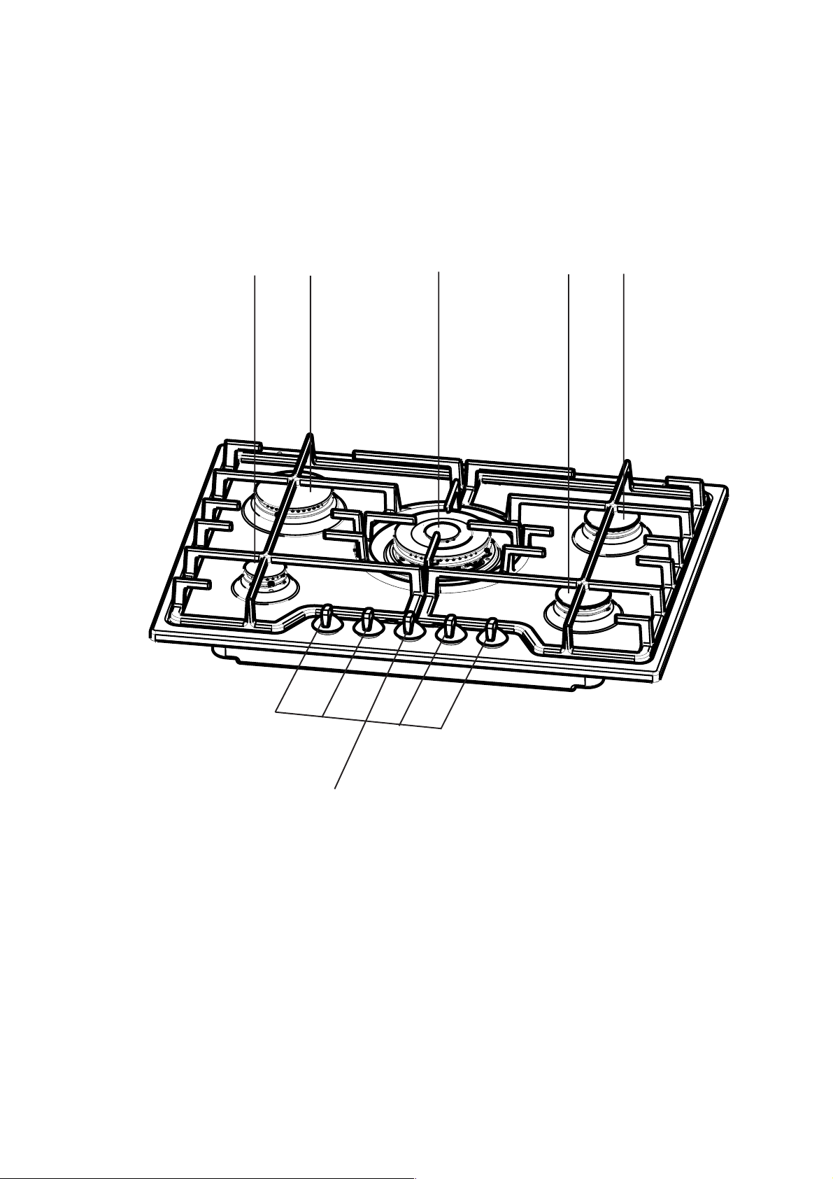
Description of the HobDescription of the Hob
Description of the Hob
Description of the HobDescription of the Hob
44
4
11
1
11
33
3
44
22
233
22
22
2
22
1. Auxiliary Burner
2. Semi-rapid Burners
3. Rapid Burner
4. Ultra-rapid Triple-crown Burner
5. Control knobs
4
55
5
55
Page 5
InstallationInstallation
Installation
InstallationInstallation
IMPORTANTIMPORTANT
IMPORTANT
IMPORTANTIMPORTANT
to the instruction supplied, and by
competent personnelcompetent personnel
competent personnel to the relevant National
competent personnelcompetent personnel
Standards.
Any gas installation must be carried out by a r egistered
CORGI installer .
The manufacturer will not accept liability, should the
above instructions or any of the other safety
instructions incorporated in this book be ignored.
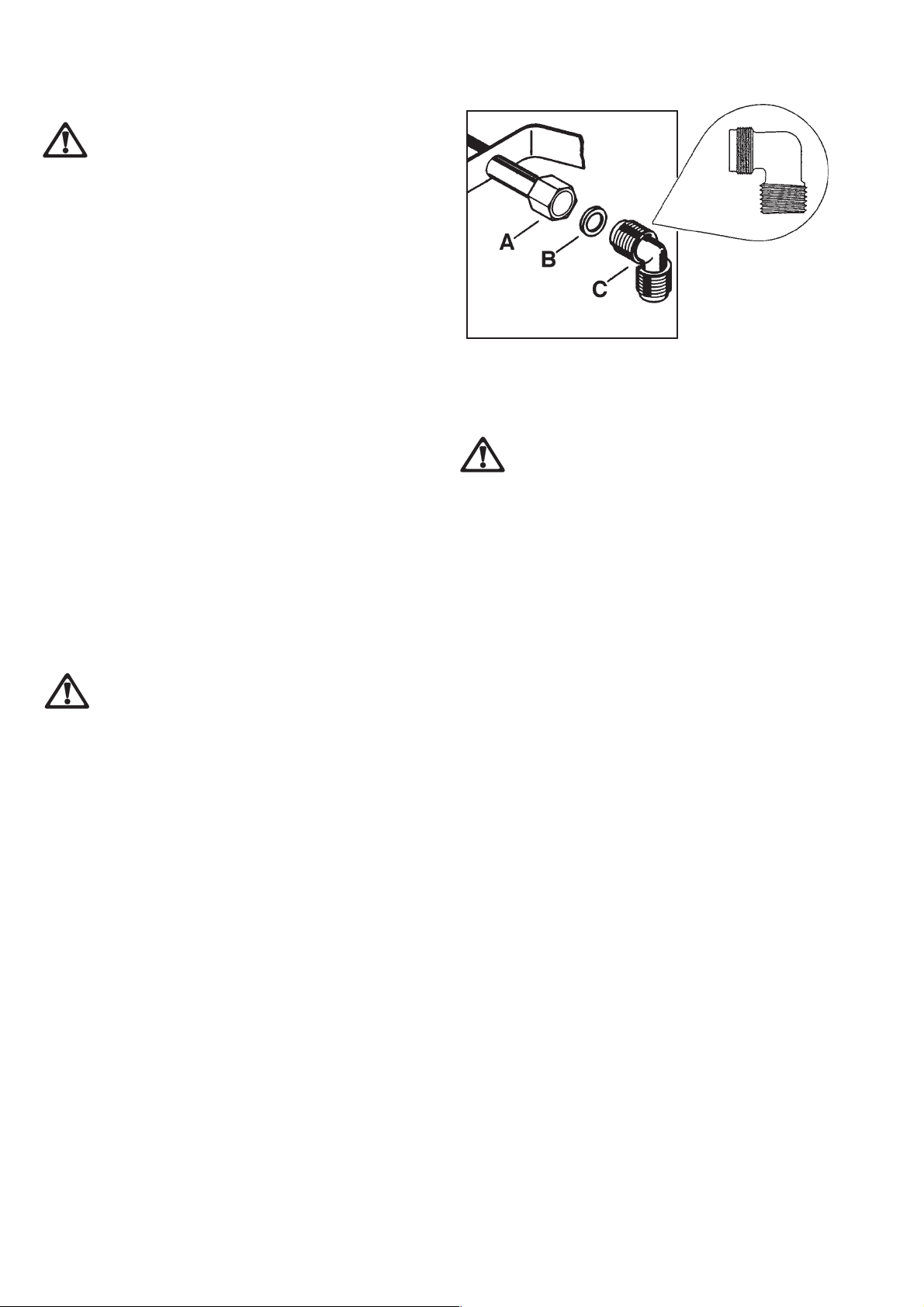
On the end of the shaft, which includes the G 1/2" threaded
elbow, adjustment is fixed so that the washer is fitted between
the components as shown in the diagram. Screw the parts
together without using excessive force.
Gas ConnectionGas Connection
Gas Connection
Gas ConnectionGas Connection
Connection to the gas supply should be with either rigid or
semi-rigid pipe, i.e. steel or copper.
The connection should be suitable for connecting to R 1/2‰
(1/2 BSP male thread). When the final connection has been
made, it is essential that a thorough leak test is carried out
on the hob and installation.
Ensure that the main connection pipe does not exert any
strain on the hob.
::
:
This hob must be installed according
::
qualified andqualified and
qualified and
qualified andqualified and
FO 0814
FO 0264
A)A)
A) End of shaft with nut
A)A)
B)B)
B) Washer
B)B)
C)C)
C ) Elbow
C)C)
It is important to install the elbow correctly , with the
shoulder on the end of the thread, fitted to the hob
connecting pipe.
Failure to ensure the correct assembly will cause
leakage of gas.
WHEN THE HOB IS FIRST INSTALLEDWHEN THE HOB IS FIRST INSTALLED
WHEN THE HOB IS FIRST INSTALLED
WHEN THE HOB IS FIRST INSTALLEDWHEN THE HOB IS FIRST INSTALLED
Once the hob has been installed, it is impor tant to
remove any protective materials, which were put on
in the factory.
5
Page 6

Instructions fInstructions f
Instructions f
Instructions fInstructions f
TT
echnical dataechnical data
T
echnical data
TT
echnical dataechnical data
OVERALL DIMENSIONSOVERALL DIMENSIONS
OVERALL DIMENSIONS
OVERALL DIMENSIONSOVERALL DIMENSIONS
or the Installeror the Installer
or the Installer
or the Installeror the Installer
Width: 680 mm
Depth: 510 mm
DIMENSIONS OF THE HOB CAVITYDIMENSIONS OF THE HOB CAVITY
DIMENSIONS OF THE HOB CAVITY
DIMENSIONS OF THE HOB CAVITYDIMENSIONS OF THE HOB CAVITY
HEATING ELEMENTS RATINGHEATING ELEMENTS RATING
HEATING ELEMENTS RATING
HEATING ELEMENTS RATINGHEATING ELEMENTS RATING
Rear Left Burner (raRear Left Burner (ra
Rear Left Burner (ra
Rear Left Burner (raRear Left Burner (ra
pid)pid)
pid)
pid)pid)
Heat Input 2.8 kW
FrFr
ont Left Burner (auxiliaront Left Burner (auxiliar
Fr
ont Left Burner (auxiliar
FrFr
ont Left Burner (auxiliaront Left Burner (auxiliar
y)y)
y)
y)y)
Heat Input 1.0 kW
Width: 560 mm
Depth: 480 mm
SUPPLY CONNECTIONSSUPPLY CONNECTIONS
SUPPLY CONNECTIONS
SUPPLY CONNECTIONSSUPPLY CONNECTIONS
Gas:Gas:
Gas:
Gas:Gas:
RC 1/2 inch (1/2 inch male) Rear right hand corner
Electric:Electric:
Electric:
Electric:Electric:
230V 50Hz supply , 3 core flexible cable with non rewir eable
plug fitted with a 3 amp cartridge fuse.
GASGAS
GASGAS
GAS
TYPE OFTYPE OF
TYPE OFTYPE OF
TYPE OF
20 mbar20 mbar
20 mbar20 mbar
20 mbar
NATURAL GASNATURAL GAS
NATURAL GASNATURAL GAS
NATURAL GAS
CHARACTERISTICS
3
3
VALUE = 37.78 MJ/m
BURNERBURNER
BURNER
BURNERBURNER
POSITIONPOSITION
POSITION
POSITIONPOSITION
NOMINAL THERMAL
POWER kW 2.8 0.65 2.0 0.45 1.0 0.33 4.0 1.2
NOMINAL FLOW
RATE m3/h 0.267 0.062 0.190 0.043 0.095 0.028 0.381 0.114
Ws - 50.7 MJ/ m
NOZZLE REFERENCE 11 3 Adjust. 96 Adjust. 70 Adjust. 146 Adjust.
1/100 mm
NOMINAL THERMAL
POWER kW 2.8 0.65 2.0 0.45 1.0 0.33 4.0 1.2
MAXMAX
MAX
MAXMAX
RAPIDRAPID
RAPID
RAPIDRAPID
(large)(large)
(large)
(large)(large)
MINMIN
MIN
MINMIN
Rear Right Burner (semi raRear Right Burner (semi ra
Rear Right Burner (semi ra
Rear Right Burner (semi raRear Right Burner (semi ra
pid)pid)
pid)
pid)pid)
Heat Input 2.0 kW
FrFr
ont Right Burner (semi raont Right Burner (semi ra
Fr
ont Right Burner (semi ra
FrFr
ont Right Burner (semi raont Right Burner (semi ra
pid)pid)
pid)
pid)pid)
Heat Input 2.0 kW
Central Burner (ultra-raCentral Burner (ultra-ra
Central Burner (ultra-ra
Central Burner (ultra-raCentral Burner (ultra-ra
pid triple-crpid triple-cr
pid triple-cr
pid triple-crpid triple-cr
oo
o
oo
wn)wn)
wn)
wn)wn)
Heat Input 4.0 kW
SEMI-RAPIDSEMI-RAPID
SEMI-RAPID
SEMI-RAPIDSEMI-RAPID
(medium)(medium)
(medium)
(medium)(medium)
MAXMAX
MAX
MAXMAX
MINMIN
MIN
MINMIN
AUXILIARYAUXILIARY
AUXILIARY
AUXILIARYAUXILIARY
(small)(small)
(small)
(small)(small)
MAXMAX
MAX
MAXMAX
MINMIN
MIN
MINMIN
ULTRA-RAPIDULTRA-RAPID
ULTRA-RAPID
ULTRA-RAPIDULTRA-RAPID
(triple-crown(triple-crown
(triple-crown)
(triple-crown(triple-crown
MAXMAX
MAX
MAXMAX
MINMIN
MIN
MINMIN
LPG GASLPG GAS
LPG GASLPG GAS
LPG GAS
28-30/37 mbar28-30/37 mbar
28-30/37 mbar28-30/37 mbar
28-30/37 mbar
BurnerBurner
Burner
BurnerBurner
VALUE = 49.92 MJ/Kg
Dia. Tap By-passDia. Tap By-pass
Dia. Tap By-pass
Dia. Tap By-passDia. Tap By-pass
1/100 mm1/100 mm
1/100 mm
1/100 mm1/100 mm
Auxiliary 28
Semi-rapid 32
Rapid 40
Ultra-rapid 56
Aeration adjustment none
6
NOMINAL FLOW
RATE g/h 202 47 144 32 72 24 288 86
NOZZLE REFERENCE 86 4 0 71 32 50 28 98 5 6
1/100 mm
APPLIANCE CLASSAPPLIANCE CLASS
APPLIANCE CLASS: 3
APPLIANCE CLASSAPPLIANCE CLASS
APPLIANCE CAPPLIANCE C
APPLIANCE C
APPLIANCE CAPPLIANCE C
APPLIANCE GAS SUPPLAPPLIANCE GAS SUPPL
APPLIANCE GAS SUPPL
APPLIANCE GAS SUPPLAPPLIANCE GAS SUPPL
AA
TEGORTEGOR
A
TEGOR
AA
TEGORTEGOR
YY
Y: II2H3+
YY
YY
Y: Natural gas G20 / 20mbar
YY
Page 7
Electrical ConnectionsElectrical Connections
Electrical Connections
Electrical ConnectionsElectrical Connections
THIS HOB MUST BE EARTHIS HOB MUST BE EAR
THIS HOB MUST BE EAR
THIS HOB MUST BE EARTHIS HOB MUST BE EAR
Any electrical work required to install this hob should
be carried out by a qualified electrician or competent
person, in accordance with the current regulations.
Electrical RequirElectrical Requir
Electrical Requir
Electrical RequirElectrical Requir
Any permanent electrical installation must comply with the
latest I.E.E. Regulations and local Electricity Board
regulations. For your own safety this should be undertaken
by a qualified electrician, e.g. your local Electricity Board,
or a contractor who is on the roll of the National Inspection
Council for Electrical Installation Contracting (NICEIC).
ementsements
ements
ementsements
THEDTHED
THED
THEDTHED
..
.
..
Electrical Connections
This hob is designed to be connected to a 230 V 50 Hz AC
electrical supply.
Before switching on, make sure the electricity supply voltage
is the same as that indicated on the hob rating plate. The
rating plate is located on the bottom of the hob. A copy is
attached on the back cover of this book.
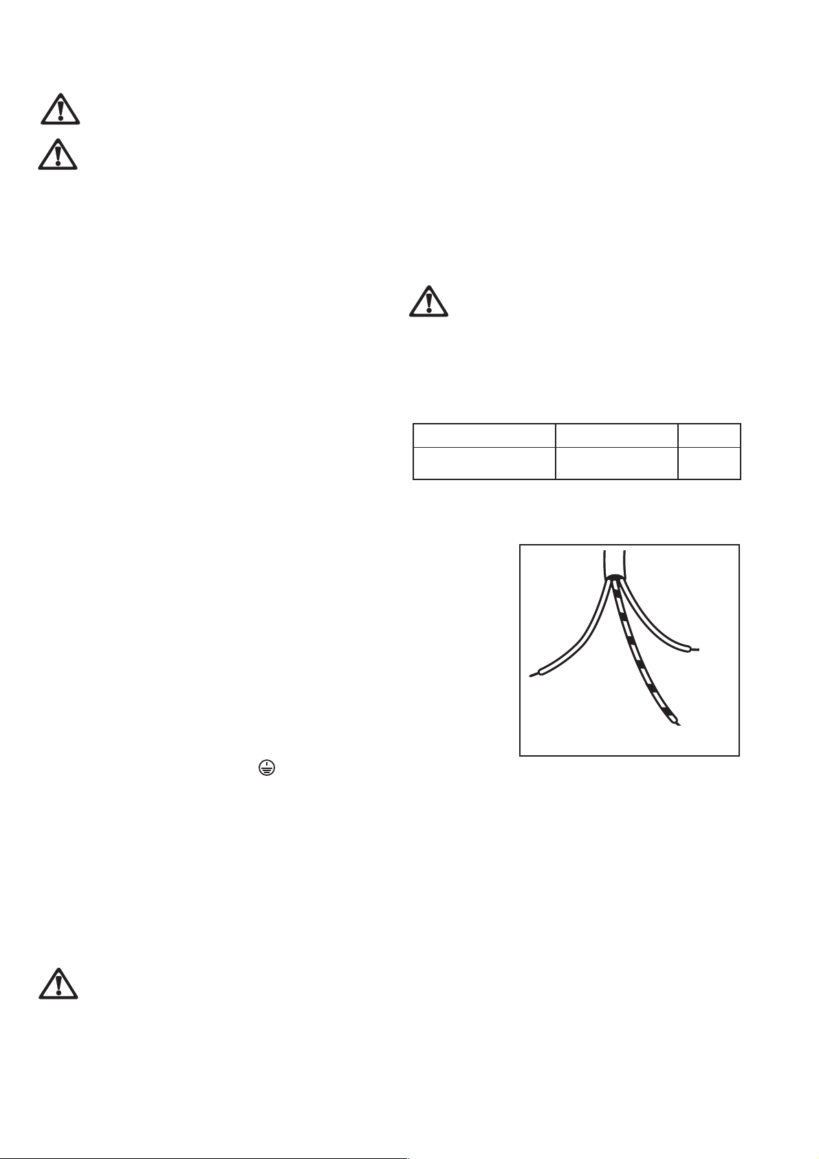
The hob is supplied with a 3 core flexible supply cables.
This has to be provided with a pr oper plug, able to support
the load marked on the identification plate. To connect the
plug to the cable, follow the recommendation given in diagram
aside. The plug has to be fitted in a proper socket.
In the event of having to change the fuse , a 3amp ASTA
approved (BS 1362) fuse must be used.
Should the plug need to be replaced for any reason, the
wires in the mains lead ar e coloured in accor dance with the
following code:
PP
ermanent Connectionermanent Connection
P
ermanent Connection
PP
ermanent Connectionermanent Connection
In the case of a permanent connection, it is necessar y that
you install a double pole switch between the hob and the
electricity supply (mains), with a minimum gap of 3 mm
between the switch contacts and of a type suitable for the
required load in compliance with the current electric
regulations.
The switch must not break the y ellow and green earth cable
at any point.
EnsurEnsur
e that the hob supple that the hob suppl
Ensur
e that the hob suppl
EnsurEnsur
e that the hob supple that the hob suppl
come into contact with surfaces withcome into contact with surfaces with
come into contact with surfaces with
come into contact with surfaces withcome into contact with surfaces with
temperaturtemperatur
temperatur
temperaturtemperatur
SupplSuppl
Suppl
SupplSuppl
The cable used to connect the hob to the electrical supply
must comply to the specifications given below.
Min. size Cable/flexMin. size Cable/flex
Min. size Cable/flex
Min. size Cable/flexMin. size Cable/flex
0.75 mm
The manufacturer declines any liability shouldThe manufacturer declines any liability should
The manufacturer declines any liability should
The manufacturer declines any liability shouldThe manufacturer declines any liability should
these safety measures not be observed.these safety measures not be observed.
these safety measures not be observed.
these safety measures not be observed.these safety measures not be observed.
y cable ry cable r
y cable r
y cable ry cable r
2
es higher than 50 deg.es higher than 50 deg.
es higher than 50 deg.
es higher than 50 deg.es higher than 50 deg.
eplacementeplacement
eplacement
eplacementeplacement
Cable / flex typeCable / flex type
Cable / flex type
Cable / flex typeCable / flex type
H05 V2V2-F (T90) 3 A
y cable does noty cable does not
y cable does not
y cable does noty cable does not
C C
..
C
.
C C
..
FuseFuse
Fuse
FuseFuse
Green and Yellow - Earth
Blue - Neutral
Brown - Live
— Connect the green and yellow (earth) wire to the
Upon completion there must be no cut, or stray strands of
wire present and the cable clamp must be secure over the
outer sheath.
terminal in the plug which is marked with the
letter 'E' or the earth symbol or coloured green
and yellow.
— Connect the blue (neutral) wire to the terminal
in the plug which is marked with the letter 'N' or
coloured black.
— Connect the brown (liv e) wir e to the terminal in
the plug which is marked with the letter 'L' or
coloured red.
A cut off plug inserA cut off plug inser
A cut off plug inser
A cut off plug inserA cut off plug inser
is a serious safis a serious saf
is a serious saf
is a serious safis a serious saf
the cut off plug is disposed of safthe cut off plug is disposed of saf
the cut off plug is disposed of saf
the cut off plug is disposed of safthe cut off plug is disposed of saf
ted into a 13 amp sockted into a 13 amp sock
ted into a 13 amp sock
ted into a 13 amp sockted into a 13 amp sock
ety (shock) hazarety (shock) hazar
ety (shock) hazar
ety (shock) hazarety (shock) hazar
d.d.
Ensur Ensur
d.
Ensur
d.d.
Ensur Ensur
elel
el
elel
yy
..
y
.
yy
..
e thate that
e that
e thate that
etet
et
etet
NeutralNeutral
Neutral
NeutralNeutral
Earth (yellow/green)Earth (yellow/green)
Earth (yellow/green)
Earth (yellow/green)Earth (yellow/green)
7
Page 8

Wiring DiagramWiring Diagram
Wiring Diagram
Wiring DiagramWiring Diagram
L
1
N
N
Fault FindingFault Finding
Fault Finding
Fault FindingFault Finding
Blue
Blue
Green
Yellow
Green
Yellow
STARTSTART
START
STARTSTART
Isolate appliance
and carry out:
A:A:
A: Earth Continuity
A:A:
check.
NONO
NO
NONO
Brown
Brown
YESYES
YES
YESYES
1
L
2
3
4
5
N
6
2
PrPr
eliminareliminar
Pr
eliminar
PrPr
eliminareliminar
CheckCheck
Check
CheckCheck
Carry out:
B:B:
B: Insulation check.
B:B:
1. IGNITOR SWITCHES1. IGNITOR SWITCHES
1. IGNITOR SWITCHES
1. IGNITOR SWITCHES1. IGNITOR SWITCHES
2. IGNITOR UNIT2. IGNITOR UNIT
2. IGNITOR UNIT
2. IGNITOR UNIT2. IGNITOR UNIT
y Electrical Systemsy Electrical Systems
y Electrical Systems
y Electrical Systemsy Electrical Systems
Electricity supply
should now be
satisfactory.
Has inlet fuse blown?
NONO
NO
NONO
Inlet wiring
faulty.
Rectify any
fault.
Isolate appliance and
carry out:
B:B:
B: Insulation check.
B:B:
Rectify any fault
including replacing
fuses as necessary.
YESYES
YES
YESYES
A.A.
EAR EAR
A.
A.A.
must be electrically disconnected - meter set on W
(Ohms) x 1 scale and adjust zero if necessary.
a) Test leads from any appliance earth point to earth
B.B.
B.
B.B.
disconnected, all switches ON.
a) meter set on W (Ohms) x 1 scale.
b) meter set on W (Ohm) x 100 scale.
NO TE - Should it be found that the fuse has failed but
no fault is indicated - a detailed continuity check (i.e.
by disconnecting and checking each component) is
required to trace the faulty component.
It is possible that a fault could occur as a result of
local burning/arcing but no fault could be found under
test. Howev er a detailed visual inspection should reveal
evidence of burning around the fault.
TH CONTINUITY CHECKTH CONTINUITY CHECK
EAR
TH CONTINUITY CHECK - Appliance
EAR EAR
TH CONTINUITY CHECKTH CONTINUITY CHECK
pin on plug. Resistance should be less than 0.1 W
(Ohm), check all earth wires for continuity and all
contacts are clean and tight.
INSULA INSULA
INSULA
INSULA INSULA
Test leads from L to N in appliance terminal block.
If meter reads «0» then there is a short circuit.
Repeat test with leads from L to E. If meter reads
less than ¥ (infinity) there is a fault.
TION CHECKTION CHECK
TION CHECK - Appliance electrically
TION CHECKTION CHECK
8
Page 9

Fault FindingFault Finding
Fault Finding
Fault FindingFault Finding
Does ignitor spark?
NONO
NO
NONO
Check plug top fuse and
replace if necessary
YESYES
YES
YESYES
Check gas supply at
burner
Light burner manually
Check polarity and earth
continuity of supply point
Check earth continuity
of appliance
Check continuity from 'N' on the
mains connector block and "N" on
the ignitor unit
Check continuity from 'L' on the
mains connector block and the
taps ignition switches
Check continuity from ignition
switches connector to ignitor unit “L”
Check continuity from the tip of
each electrode to the terminals 1
to 4 on the ignitor unit
Check for breaks in the insulation
of the HT leads
Change the taps ignition
switches
Check by pass simmer
adjusted
Check position of the
electrode
Check fitting of burners
Change the ignitor unit
9
Page 10

CommissioningCommissioning
Commissioning
CommissioningCommissioning
When the hob has been fully installed it will be necessary to
check the minimum flame setting. To do this, follow the procedure below.
Turn the gas tap to the MAX position and ignite.
Set the gas tap to the MIN flame position then turn the
control knob from MIN to MAX sev eral times. If the flame
is unstable or is extinguished follow the procedure below .
PrPr
ocedurocedur
Pr
ocedur
PrPr
ocedurocedur
Pressure TestingPressure Testing
Pressure Testing
Pressure TestingPressure Testing
e:e:
e:
e:e:
Re-ignite the burner and set to MIN.
Remove the control knob.
To adjust, use a thin bladed screwdriver and turn
the adjustment screw (see diagram) until the flame
is steady and does not extinguish, when the knob
is turned from MIN to MAX. Repeat this procedure for all burners.
Remove left hand pan support and front left burner
cap and crown.
Fit manometer tube over the injector.
Turn on the burner gas supply and ignite another
burner.
The pressure reading should be nominall y 20mbar
and must be between 17 mbar and 25mbar.
Turn off the burner supplies.
MinimMinim
um adjustment scrum adjustment scr
Minim
um adjustment scr
MinimMinim
um adjustment scrum adjustment scr
ee
ww
e
w
ee
ww
ConCon
Con
ConCon
It is important to note that this model is designed for use
with natural gas but can be converted for use with butane
or propane gas pro viding the correct injectors are fitted. The
gas rate is adjusted to suit.
Proceed as followProceed as follow
Proceed as follow
Proceed as followProceed as follow
• Ensure that the gas taps are in the 'OFF' position
• Isolate the hob from the electrical supply
• Remove all pan supports, burner caps, rings, crowns and
control knobs.
• With the aid of a 7mm box spanner the burner injectors
can then be unscrewed and r eplaced b y the appropriate
LPG injectors.
10
vv
ersion frersion fr
v
ersion fr
vv
ersion frersion fr
om Natural Gas to LPGom Natural Gas to LPG
om Natural Gas to LPG
om Natural Gas to LPGom Natural Gas to LPG
TT
o adjust the gas rateo adjust the gas rate
T
o adjust the gas rate
TT
o adjust the gas rateo adjust the gas rate
With the aid of a thin bladed screwdriv er completely tighten
down the by pass adjustment screw. Upon completion stick
the replacement rating plate on the under side of the hob.
IMPORTANTIMPORTANT
IMPORTANT
IMPORTANTIMPORTANT
The rThe r
eplacement/coneplacement/con
The r
eplacement/con
The rThe r
eplacement/coneplacement/con
onlonl
y be undery be under
onl
y be under
onlonl
y be undery be under
taktak
tak
taktak
vv
ersion of the gas hob shouldersion of the gas hob should
v
ersion of the gas hob should
vv
ersion of the gas hob shouldersion of the gas hob should
en ben b
y a competent person.y a competent person.
en b
y a competent person.
en ben b
y a competent person.y a competent person.
Page 11
Building InBuilding In
ON/OFF SWITCH
FLEX
OUTLET
Building In
Building InBuilding In
IMPORTANTIMPORTANT
IMPORTANT
IMPORTANTIMPORTANT
to the instruction supplied, and by
competent personnelcompetent personnel
competent personnel to the relevant National
competent personnelcompetent personnel
Standards.
Please ensure that when the hob is installed it is easily
accessible for the engineer in the event of a breakdown.
BB
uilding ouilding o
B
uilding o
BB
uilding ouilding o
dradra
ww
w
ww
erer
er
erer
dra
dradra
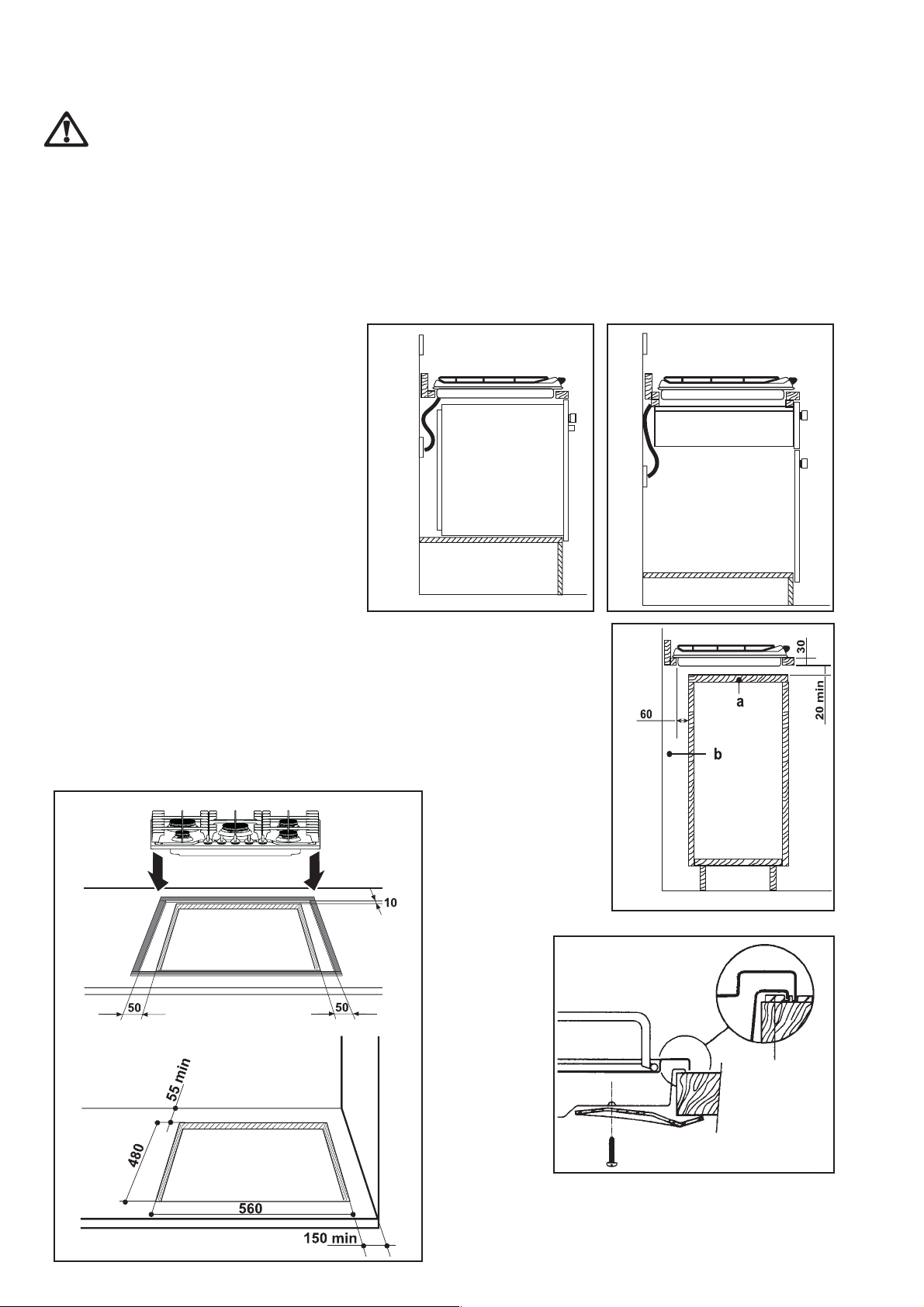
If the hob is to be installed above a cupboard or
drawer it will be necessary to fit a heat resistant
board below the base of the hob on the underside
of the work surface.
It is also recommended to carry out the electrical
connection to the hob as shown in diagrams 1
and 2.
::
:
This hob must be installed according
::
qualified andqualified and
qualified and
qualified andqualified and
vv
er a cupboarer a cupboar
v
er a cupboar
vv
er a cupboarer a cupboar
d ord or
d or
d ord or
11
1
11
FLEX
OUTLET
BB
uilding ouilding o
B
uilding o
BB
uilding ouilding o
doordoor
door
doordoor
Proper arrangements must be tak en in designing the furniture
unit, in order to avoid any contact with the bottom of the
hob which can be heated when it is operated. The
recommended solution is shown in diagram 3.
The panel fitted under the hob ("a") should be easily
removable to allow easy access if technical assistance is
needed. The space behind the kitchen unit ("b") can be used
for connections.
ON/OFF SWITCH
vv
er a kitchen unit wither a kitchen unit with
v
er a kitchen unit with
vv
er a kitchen unit wither a kitchen unit with
22
2
22
Dimensions are given in mm
Fitting the Hob into the wFitting the Hob into the w
Fitting the Hob into the w
Fitting the Hob into the wFitting the Hob into the w
Carry out the building in of the hob as follows:
• put the seals supplied with the hob, on the edges of the cut out like shown in
The edge of the hob forms a double seal which prevents the penetration of liquids.
the fig. 4, taking care that the seals meet without overlapping;
• place the hob in the cut out, taking care that it is centred;
• fix the hob with the relevant fixing clamps and scr ews, as sho wn in the diagram
5. When the screws have been tightened, the excess seal can be removed.
FO 2563
orktoporktop
orktop
orktoporktop
44
4
44
FO
2564
33
3
33
FO 2044
55
5
55
Seal
a
FO 0199
11
Page 12

ImporImpor
Impor
ImporImpor
tant saftant saf
tant saf
tant saftant saf
ety rety r
ety r
ety rety r
equirequir
equir
equirequir
ementsements
ements
ementsements
This hob must be installed in accordance with the Gas Safety
(Installation and Use) Regulations (Current Edition) and the
IEE Wiring Regulations (Current Edition).
PrPr
oo
vision fvision f
Pr
o
vision f
PrPr
oo
vision fvision f
Detailed recommendations are contained in the following
National Standards Codes Of Practice: B.S. 6172/ B.S. 5440,
Part 2 and B.S. 6891 Current Editions.
The hob should not be installed in a bed sitting room with
a volume of less than 20 m3. If it is installed in a room of
volume less than 5 m3 an air vent of effective area of 110
cm2 is required. If it is installed in a r oom of v olume between
5 m3 and 10 m3 an air vent of effective area of 50 cm2 is
required, while if the volume exceeds 11 m3 no air vent is
required. However, if the room has a door which opens
directly to the outside no air vent is required even if the
volume is between 5 m3 and 11 m3. If there are other fuel
burning appliances in the same room, B.S. 5440 Part 2
Current Edition, should be consulted to determine the requisite air vent requir ements.
or vor v
or v
or vor v
entilationentilation
entilation
entilationentilation
66
6
66
700 mm
100 mm
FO 2369*
77
7
77
FITTING THE GAS HOB
WITHOUT A COOKER HOOD ABOVE
400 mm
50 mm
FITTING THE GAS HOB
WITH A COOKER HOOD ABOVE
600 mm
55 mm
600 mm
400 mm
50 mm
LocationLocation
Location
LocationLocation
The hob may be located in a kitchen, a kitchen/diner or bed
sitting room, but not in a bathroom or shower room.
Before making the cut out in the worktop ensure that the
edges of the hob that are to be near either a side or rear
wall have a minimum distance of 55 mm between the edge
of the hob and the wall.
The minimum distance combustible material can be fitted
above the hob is 400 mm - without a cooker hood above
see fig.6. If it is fitted belo w 400 mm a space of 50 mm must
be allowed from the edges of the hob . The minimum distance
combustible material can be fitted directly above the hob is
700 mm - with a cooker hood above see fig.7. A minimum
distance of 100 mm must be left between the side edges of
the hob and any adjacent cabinets or walls.
650 mm
1
0
FO 2231*
400 mm
55 mm
0
m
m
50 mm
400 mm
50 mm
12
Page 13

Using the hobUsing the hob
Using the hob
Using the hobUsing the hob
BurnersBurners
Burners
BurnersBurners
To light a burner:
push in the relevant control knob and turn it anticlockwise
to maximum position;
then adjust the flame as required.
If the burner does not ignite, turn the control knob to zer o ,
and try again.
To ensure maximum burner efficiency, you should only use
pots and pans with a flat bottom fitting the size of the burner
used (see table).
Hints and Hints and
Hints and
Hints and Hints and
If yIf y
ou use a saucepan which is smaller than the rou use a saucepan which is smaller than the r
If y
ou use a saucepan which is smaller than the r
If yIf y
ou use a saucepan which is smaller than the rou use a saucepan which is smaller than the r
bottom of the vbottom of the v
bottom of the v
bottom of the vbottom of the v
TT
akak
e care car
e car
e care car
e when fre when fr
e when fr
e when fre when fr
T
ak
TT
akak
As soon as a liquid starts boiling, turn down the flame so that it will barely keep the liquid simmering.
If the control knobs become difficult to turn, please contact your local Repair agent.
Cleaning the hobCleaning the hob
Cleaning the hob
Cleaning the hobCleaning the hob
TipsTips
Tips
TipsTips
essel,essel,
causing the handle to o causing the handle to o
essel,
causing the handle to o
essel,essel,
causing the handle to o causing the handle to o
ying fying f
ood in hot oil or fat,ood in hot oil or fat,
ying f
ood in hot oil or fat,
ying fying f
ood in hot oil or fat,ood in hot oil or fat,
BurnerBurner
Burner
BurnerBurner
Ultra-rapid
(triple-crown) 180 mm 260 mm
Large (rapid) 180 mm 260 mm
Medium (semi-rapid) 120 mm 220 mm
Small (auxiliary) 80 mm 160 mm
ecommended sizeecommended size
ecommended size
ecommended sizeecommended size
vv
erheat.erheat.
v
erheat.
vv
erheat.erheat.
as the o as the o
as the o
as the o as the o
vv
erheated splashes could easilerheated splashes could easil
v
erheated splashes could easil
vv
erheated splashes could easilerheated splashes could easil
minimumminimum
minimum
minimumminimum
diameterdiameter
diameter
diameterdiameter
,,
the flame will spr the flame will spr
,
the flame will spr
,,
the flame will spr the flame will spr
maximummaximum
maximum
maximummaximum
ead beead be
ead be
ead beead be
y ignitey ignite
y ignite
y ignitey ignite
diameterdiameter
diameter
diameterdiameter
yy
ond theond the
y
ond the
yy
ond theond the
..
.
..
The Hob The Hob
The Hob
The Hob The Hob
Regularly wipe over the hob top using a soft cloth well wrung
out in warm water to which a little washing up liquid has
been added. Avoid the use of the following:
- household detergent and bleaches;
- impregnated pads unsuitable for non-stick saucepans;
- steel wool pads;
- bath/sink stain removers.
Should the hob top become heavily soiled, it is recommended
that a cleaning product such as Hob Brite or Bar Keepers
Friend available from your John Lewis local branch is used.
Pan SupporPan Suppor
Pan Suppor
Pan SupporPan Suppor
The pan supports are dishwasher proof. If washing them by
hand, take care when drying them as the enamelling process
occasionally leaves rough edges. If necessary, remove stubborn
stains using a paste cleaner.
The BurnersThe Burners
The Burners
The BurnersThe Burners
The burner caps and crowns can be removed for cleaning.
Wash the burner caps and crowns using hot soapy water,
and remove marks with a mild paste cleaner. A well moistened
soap impregnated steel wool pad can be used with caution,
if the marks are particularly difficult to remove.
After cleaning, be sure to wipe dry with a soft cloth.
TT
T
TT
opop
op
opop
tsts
ts
tsts
Before any maintenance or cleaning can be carried
out, you must
electricity supply .
The hob is best cleaned whilst it is still warm, as
spillage can be removed mor e easily than if it is left to
cool.
DISCONNECTDISCONNECT
DISCONNECT the hob from the
DISCONNECTDISCONNECT
13
Page 14

Something Not Something Not
Something Not
Something Not Something Not
If the hob is not working correctly, please carry out the following checks befo re contacting your local Service Force repair
agent.
IMPORTANT: if you call out an engineer to fault listed below, or to repair a fault caused by incorrect use or installation, a
charge will be made even if the appliance is under guarantee.
WW
orking?orking?
W
orking?
WW
orking?orking?
SYMPTOMSYMPTOM
SYMPTOM
SYMPTOMSYMPTOM
There is no spark when lighting the gas
The gas ring burns unevenly
SOLUTIONSOLUTION
SOLUTION
SOLUTIONSOLUTION
Check that the unit is plugged in and the electrical
supply is switched on
Check that the RCCB has not tripped (if fitted)
Check the mains fuse has not blown
Check the burner cap and crown have been replaced
correctly, e.g. after cleaning.
Check the main jet is not blocked and the burner
crown is clear of food particles.
Check the burner cap and crown have been replaced
correctly, e.g. after cleaning.
14
Page 15

Repairs - Repairs -
Repairs -
Repairs - Repairs -
If your hob is not performing satisfactorily; consult the fault
finding guide within this instruction book (Something not
working on the previous page). In the event of a fault
occurring which you cannot resolve yourself from advice
given within this instruction manual.
Your first step is to contact our extended warranty
administrators on
of your local Service Force repair agent.
When contacting Service Force, please quote the model
(Mod.) and serial number (S.N.). These details have been
provided separately within the pack containing this
instruction manual.
So that you always have these numbers at hand, we
recommend you to mak e a note of them here:
Mod. : . . . . . . . . . . . . . . . . . .
PNC : . . . . . . . . . . . . . . . . . .
S.N. : . . . . . . . . . . . . . . . . . . .
Your hob is covered by a 3 year parts and labour guarantee
(see separate details given at point of sale). Please retain
your purchase receipt saf ely for the service engineer to verify
the purchase details.
0870 01078870870 0107887
0870 0107887 who will give you details
0870 01078870870 0107887
After Sales SerAfter Sales Ser
After Sales Ser
After Sales SerAfter Sales Ser
vicevice
vice
vicevice
SparSpar
Spar
SparSpar
This product should be serviced by an authorised service
engineer, and only genuine spare parts should be used.
Under no circumstances should you attempt to repair the
hob yourself.
Repairs carried out by inexperienced persons may cause
injury or serious malfunctioning. Contact our extended
warranty administrators on
you details for your local Service Force repair agent.
Always insist on genuine spare parts.
e pare par
e par
e pare par
tsts
ts
tsts
0870 01078870870 0107887
0870 0107887 who will give
0870 01078870870 0107887
15
Page 16

JJ
ohn Leohn Le
J
ohn Le
JJ
ohn Leohn Le
171 Victoria Street
London SW1E 5NN
www.johnlewis.com
wis Parwis Par
wis Par
wis Parwis Par
tnershiptnership
tnership
tnershiptnership
35690-7201 01/06
Grafiche MDM - Forlì
 Loading...