

Page 1

ET -3504-J
1/2-INCH DRILL
CAUTION
RISK OF INJURY!
AND SHOULD REMAIN WITH THIS UNIT WHEN YOU SELL OR RENT IT.
THIS MANUAL IS AN IMPORTANT PART OF THE DRILL
1/2-Inch Drill Operator's Manual 1
READ MANUAL BEFORE OPERATING!
Page 2

Introduction
Congratulations on the purchase of your new drill! You can be assured your drill was
constructed and designed with quality and performance in mind. Each component has
been rigorously tested to ensure the highest level of acceptance.
This operator's manual was compiled for your benefit. By reading and following the simple
safety, installation, operation, maintenance and troubleshooting steps described in this
manual, you will receive years of trouble-free operation from your new tool. The contents
of this manual are based on the latest product information available at the time of
publication. The manufacturer reserves the right to make changes in price, color, materials, equipment, specifications or models at any time without notice.
Once the unit has been removed from the box, immediately write in the serial number of your
unit in the space provided below.
SERIAL NUMBER_________________________________
Inspect for signs of obvious or concealed freight damage. If damage does exist, file a claim
with the transportation company immediately. Be sure that all damaged parts are replaced and
that the mechanical problems are corrected prior to operation of the unit. If you require service,
contact your Customer Service.
Mi-T-M® Corporation, 8650 Enterprise Drive, Peosta, IA 52068
1-877-JD-KLEEN / (1-877-535-5336) Fax 563-556-1235
Monday - Friday 8:00 a.m. - 5:00 p.m. CST
Please have the following information available for all service calls:
1. Model Number
2. Serial Number
3. Date and Place of Purchase
WARNING
WEAR RESPIRAT ORY PROTECTION
Some dust created by power sanding, sawing, grinding, drilling and other construction
activities contain chemicals known to the State of California to cause cancer, birth
defects or other reproductive harm. Some examples of these chemicals are:
• Lead from lead-base paints,
• Crystalline Silica from bricks, cement and other masonry products, and
• Arsenic and Chromium from chemically-treated lumber.
Your risk from these exposures varies, depending on how often you do this type of work.
To reduce your exposure to these chemicals, work in a well ventilated area and work
with approved safety equipment, such as those dust masks that are specially designed
to filter out microscopic particles.
2 1/2-Inch Drill Operator's Manual
Page 3

Table of Content
SAFETY .................................................................................................................. 4-9
FUNCTIONAL DESCRIPTION............................................................................... 10
PREPARATION ...................................................................................................... 10
OPERATION........................................................................................................... 11-12
MAINTENANCE AND INSPECTION ..................................................................... 12-13
NOTES ................................................................................................................... 14-15
GENERAL SAFETY RULES.................................................................. 4-9
MODEL................................................................................................... 10
NAME OF PARTS.................................................................................. 10
SPECIFICATIONS ................................................................................. 10
APPLICATIONS ..................................................................................... 11
PRE-OPERATION ................................................................................. 11-12
OPERATION .......................................................................................... 12
STANDARD ACCESSORIES ................................................................ 12
MAINTENANCE AND INSPECTION ..................................................... 13
SERVICE AND REPAIRS...................................................................... 13
REPLACEMENT PARTS ....................................................................... 13
1/2-Inch Drill Operator's Manual 3
Page 4
W
ARNIN
G
W
A
R
N
I
NG
SIN
T
HEM
A
NUA
LS
.
W
A
RN
I
NG
SIN
T
HEMA
NUA
LS
.
CA
U
T
I
ON
OCAUT
I
ON
S
IN
O
T
H
E
M
A
N
UA
L
S
OC
AUT
I
ON
S
IN
O
T
H
E
M
A
N
UA
L
S
OC
AUT
I
ON
S
IN
O
T
H
E
M
A
N
UA
L
S
OCAUT
I
ON
S
IN
O
T
H
E
M
A
N
UA
L
S
DANGER
WARNING
CAUTION
Safety
RECOGNIZE SAFETY INFORMATION
This is the safety alert symbol. When you see this symbol on
your tool or in this manual, be alert to the potential for
personal injury.
Follow recommended precautions and safe operating
practices.
UNDERSTAND SIGNAL WORDS
A "DANGER, WARNING or CAUTION" safety warning will be
surrounded by a "SAFETY ALERT BOX." This box is used to
designate and emphasize Safety Warnings that must be
followed when operating this tool.
Accompanying the Safety Warnings are "signal words" which
designate the degree or level of hazard seriousness. The
"signal words" used in this manual are as follows:
DANGER: Indicates an imminently hazardous situation
which, if not avoided, WILL result in death or
serious injury.
WARNING: Indicates a potentially hazardous situation
which, if not avoided, COULD result in death or
serious injury.
CAUTION: Indicates a potentially hazardous situation
which, if not avoided MAY result in minor or
moderate injury.
GENERAL SAFETY RULES
WARNING: Read and understand all
instructions.
Failure to follow all
instructions listed below, may
result in electric shock, fire and/
or serious personal injury.
SAVE THESE INSTRUCTIONS
4 1/2-Inch Drill Operator's Manual
Page 5
WARNING
KEEP WORK AREA CLEAN AND WELL LIT.
Cluttered areas and benches invite injuries.
CONSIDER WORK AREA ENVIRONMENT.
Don't expose power tools to rain. Don't use power
tools in damp or wet locations. Keep work area well
lit. Don't use tool in presence of flammable liquids
or gases. Power tools produce sparks during
operation. They also spark when switching ON/
OFF. Never use power tools in dangerous sites
containing lacquer, paint, benzine, thinner, gasoline,
gases, adhesive agents, and other materials which
are combustible or explosive.
GUARD AGAINST ELECTRIC SHOCK
Prevent body contact with grounded surfaces. For
example, pipes, radiators, ranges, refrigerator
enclosures.
KEEP CHILDREN AWAY
Do not let visitors contact tool or extension cord. All
visitors should be kept away from work area.
STORE IDLE TOOLS
When not in use, tools should be stored in dry, and
high or locked location - out of reach of children.
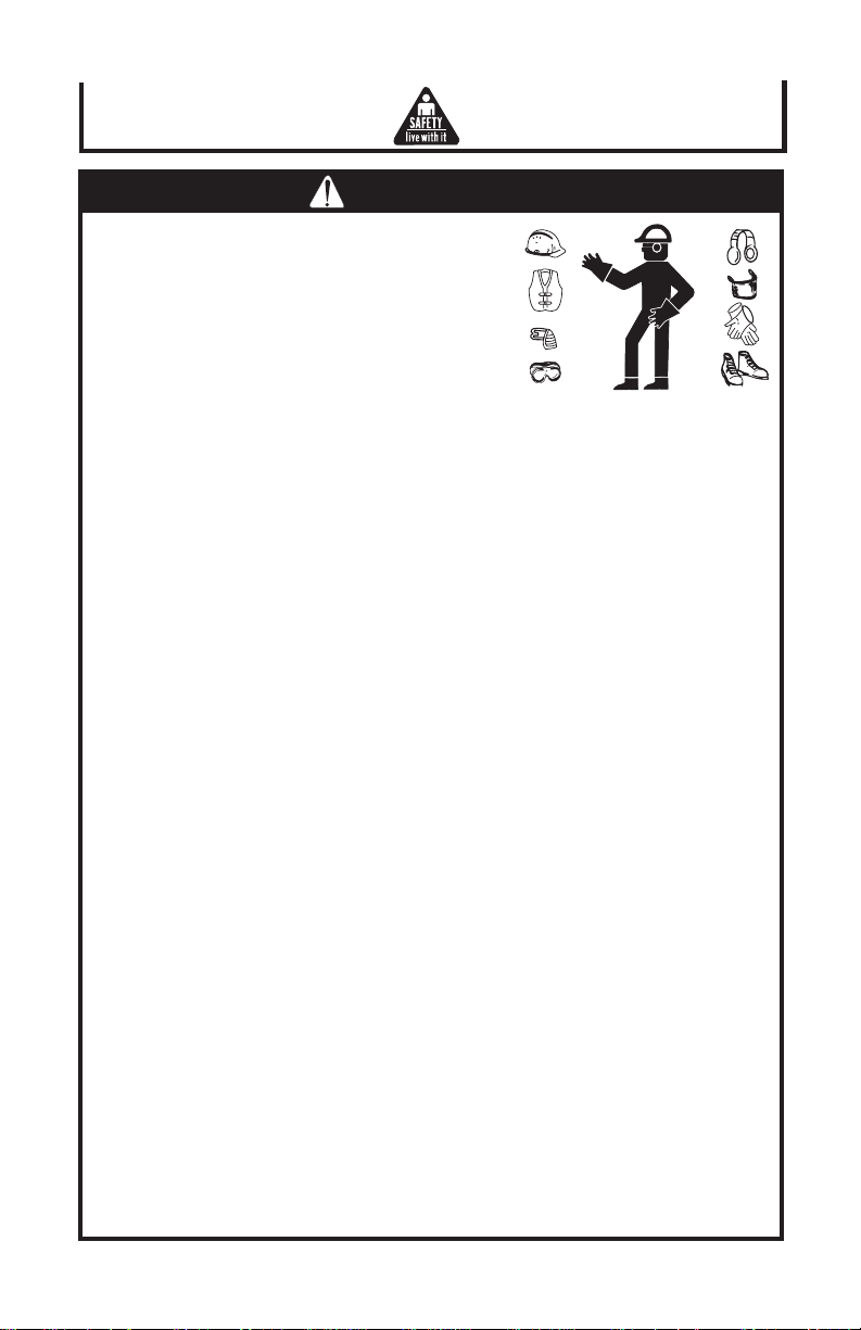
DRESS PROPERLY
Do not wear loose clothing or jewelry. They can be
caught in moving parts. Rubber gloves and nonskid
footwear are recommended when working outdoors.
USE SAFETY GLASSES
Also use face or dust mask if cutting operation is
dusty. All persons in the area where power tools re
being operated should also wear safety eye
protectors and face or dust masks.
SECURE WORK
Use clamps or a vise to hold work. It's safer than
using your hand and it frees both hands to operate
tool.
1/2-Inch Drill Operator's Manual 5
Page 6
WARNING
DON'T OVERREACH
Keep proper footing and balance at all times.
MAINTAIN TOOLS WITH CARE
Keep tools sharp and clean for better and safer performance. Follow instructions for
lubricating and changing accessories. Inspect tool cords periodically and replace if
damaged, have repaired by authorized service facility. Inspect extension cords
periodically and replace if damaged. Keep handles dry, clean, and free from oil and
grease.
DISCONNECT TOOLS
When not in use, before servicing, and when changing accessories, such as blades,
bits, cutters.
AVOID UNINTENTIONAL STARTING
Don't carry plugged-in tool with finger on switch. Be sure switch is off when plugged
in.
SECURELY MOUNT ACCESSORIES AND BLADES TO THE TOOL MAIN BODY
Extra care must be taken when using tools on elevated location (such as a roof
ladder, scaffold, or the like) to prevent injury to someone on a lower level in the event
the tool and/or accessory should drop.
NEVER TOUCH THE MOVING PARTS
Never touch the moving parts such as blades, bits, cutters and others.
CAUTION
DON'T FORCE TOOL
It will do the job better and safer at the rate from which it was intended.
USE RIGHT TOOL
Don't force small tool or attachment to do the job of a heavy-duty tool. Don't use tool for
purpose not intended - for example - don't use circular saw for cutting tree limbs or logs.
DON'T ABUSE CORD
Never carry tool by cord or yank it to disconnect from receptacles. Keep cord from heat,
oil and sharp edges.
REMOVE ADJUSTING KEYS AND WRENCHES
Form habit of checking to see that keys and adjusting wrenches are removed from tool
before turning it on.
6 1/2-Inch Drill Operator's Manual
Page 7

CAUTION
OUTDOOR USE EXTENSION CORDS
When tool is used outdoors, use only extension cords intended for use outdoors and
so marked.
STAY ALERT
Watch what you are doing. Use common sense. Do not operate tool when you are
tired.
CHECK DAMAGED PARTS
Before further use of the tool, a guard or other part that is damaged should be
carefully checked to determine that it will operate properly and perform its intended
function. Check for alignment of moving parts, binding of moving parts, breakage of
parts, mounting, and any other conditions that may affect its operation. A guard or
other part that is damaged should be properly repaired or replaced by a John Deere
Dealer unless otherwise indicated elsewhere in this instruction manual. Have
defective switched replaced by a John Deere Dealer. Do not use tool if switch does
not turn it on and off.
AVOID USING A POWER TOOL FOR APPLICATIONS OTHER THAN THOSE
SPECIFIED
Never use a power tool for applications other than those specified in the instruction
manual.
ENSURE SAFE OPERATION THROUGH CORRECT HANDLING
Secure safe operation through correct handling by observing the instructions described herein. Do not employ accessories other than those specified herein;
otherwise, a hazardous condition may be created. Never allow a power tool to be
used by persons not familiar with correct handling (such as children) or by those who
cannot handle the tool correctly.
CONFIRM THAT NO ITEMS SUCH AS AN ELECTRIC CABLE OR CONDUIT ARE
BURIED INSIDE
In places where live wiring may be hidden behind a wall, floor, ceiling, etc. do not hold
or contact any metal parts of the tool. In such cases, metal parts could become
electrically live and present a serious shock hazard.
KEEP THE RIGHT PARTS IN THE RIGHT POSITION
Do not remove covers and screws which have been factory-mounted. They perform
important respective roles. Keep them in the right positions.
SHOULD THE PLASTIC HOUSING OR HANDLE OF A POWER TOOL BE
CRACKED OR DEFORMED, DO NOT USE IT
Since cracked or deformed parts may lead to an operator receiving an electric shock,
do not use such a power tool. Immediately have it repaired.
1/2-Inch Drill Operator's Manual 7
Page 8

CAUTION
ALWAYS KEEP THE MOTOR AIR VENT FULLY OPENED
A constantly open motor air vent is necessary to allow air to come in and out for cooling
the motor. Do not allow it to become clogged up, even if dust is blown through it.
OPERATE POWER TOOLS AT THE RATED VOLTAGE
Operate power tools at voltages specified on the nameplates.
STOP OPERATION IMMEDIATELY IF ANY ABNORMALITY IS DETECTED
Should a power tool be detected as out of order or should other abnormalities be
observed during operation, stop using the tool immediately.
NEVER LEAVE TOOL RUNNING UNATTENDED. TURN POWER OFF.
Don't leave tool until it comes to a complete stop.
CAREFULLY HANDLE POWER TOOLS
Should a power tool be dropped or struck against hard materials inadvertently, it may be
deformed, cracked, or damaged.
DO NOT WIPE PLASTIC PARTS WITH SOLVENT
Solvents such as gasoline, thinner, benzine, carbon tetrachloride, and alcohol may
damage and crack plastic parts. Do not wipe them with such solvents. Wipe plastic
parts with a soft cloth lightly dampened with soapy water.
WHEN REPLACING A COMPONENT PART, ADOPT THE SAME TYPE
When replacing a component part with a new one, adopt the same type of new part.
Also, never attempt to repair a power tool yourself.
POLARIZED PLUGS
To reduce the risk of electric shock, this equipment has a polarized plug (one blade is
wider than the other).
This plug will fit in a polarized outlet only one way.
If the plug does not fit fully in the outlet, reverse the plug.
If it still does not fit, contact a qualified electrician to install the proper outlet.
Do not change the plug any way.
PRECAUTIONS ON USING DRILL
1. Attach the side handle and hold the drill firmly while using.
2. Do not wear gloves when operating.
3. Take care of downward direction in the high position.
8 1/2-Inch Drill Operator's Manual
Page 9
CAUTION
EXTENSION CORD
Make sure your extension cord is in good condition. When using an extension cord, be
sure to use one heavy enough to carry the current your product will draw. An undersized
cord will cause a drop in line voltage resulting in loss of power and overheating. Table
shows the correct size to use depending on cord length and nameplate ampere rating. If
in doubt, use the next heavier gage. The smaller the gage number, the heavier the cord.
MINIMUM GAGE FOR CORD SETS
Total Length of Code in Feet (Meter)
0-25 26-50 51-100 101-150
(0-7.6) (7.9-15.2)(15.5-30.05) (30.8-45.7)
Ampere Rating AWG Size of Cord
More Not More
Than Than
0 6 18 16 16 14
6 10181614 12
10 12 16 16 14 12
12 16 14 12 Not recommended
WARNING: AVOID ELECTRICAL SHOCK HAZARD. NEVER USE THIS TOOL
WITH A DAMAGED OR FRAYED ELECTRICAL CORD OR
EXTENSION CORD. INSPECT ALL ELECTRICAL CORDS
REGULARLY. NEVER USE IN OR NEAR WATER OR IN ANY
ENVIRONMENT WHERE ELECTRIC SHOCK IS POSSIBLE.
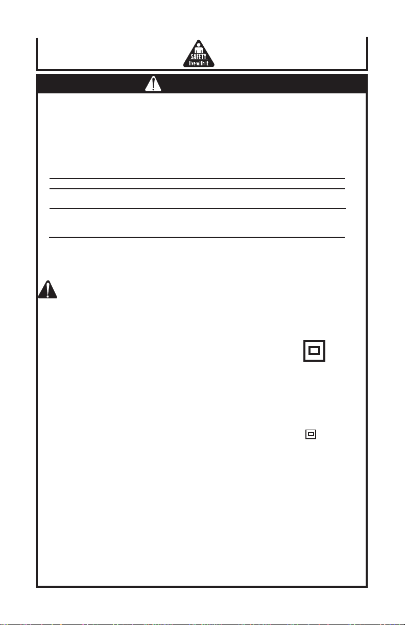
DOUBLE INSULATION SYSTEM ENHANCES SAFE OPERATION
To enhance safe operation of this electric power tool, JOHN DEERE has adopted a
double insulation system. The term "double insulation" used here denotes an insulation
systems with two insulations physically separated and arranged between the electrically
conductive material connected to the power supply and outer frame subject to contact by
the operator.
Thus, the power tool is termed double insulated and both the mark and " " double
insulation", or either one is indicated on the name plate.
While no external grounding is required with this system, normal safety precautions as
outlined in this manual must still be followed.
To maintain the effectiveness of the double insulation system, follow the precautions
described below:
1. Always contact your John Deere Dealer when assembling, disassembling or
replacing parts other than accessories or carbon brushes. Improper assembly
and/or replacement with wrong parts may result in eliminating the double
insulation-feature.
2. Clean the exterior of the tool with a soft cloth moistened with soapy water, and
dry thoroughly. Choleric solvent, gasoline, and thinner will cause plastic compo
nents to dissolve.
SAVE THESE INSTRUCTIONS AND MAKE THEM AVAILABLE TO
OTHER USERS AND OWNERS OF THIS TOOL!
1/2-Inch Drill Operator's Manual 9
Table 1
DOUBLE INSULATION
Page 10

Functional Description
MODEL:
ET-3504-J 1/2-INCH DRILL
NOTE: The information contained in this Instruction Manual is designed to assist you in
NEVER operate, or attempt any maintenance on the tool unless you have first read and
understood all safety instructions contained in this manual.
Some illustrations in this Instruction Manual may show details or attachments
that differ from those on your own power tool
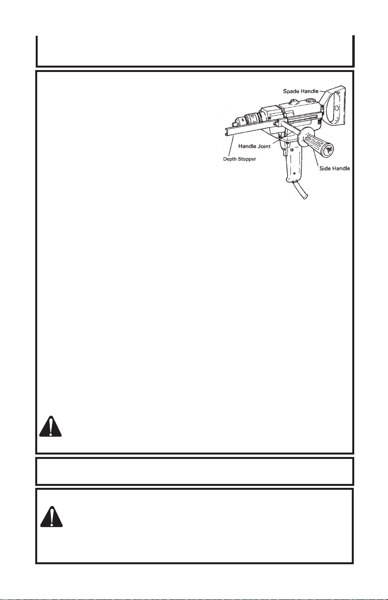
NAME OF PARTS:
SPECIFICATIONS:
1/2-INCH DRILL ET-3504-J:
Motor Single-Phase, Series: Wound Commutator Motor
Power Source Single-Phase 115V AC/DC 60Hz
Current 6.2A
Capacity 1/2” (13mm) (Steel) 1-5/8” (40mm) (Wood)
No-Load Speed 550 rpm
Weight 6.6 lbs. (3kg)
the safe operation and maintenance of the power tool.
(Fig. 1)
Preparation
PREPARATION PRIOR TO OPERATION:
Before using the Electric Power Tool, complete the following preparations.
1. Extension cord:
When the work area is far away from the power source,use an extension cord of
sufficient thickness and rated capacity. The extension cord should be kept as short
as possible.
CAUTION: DAMAGED CORD MUST BE REPLACED OR REPAIRED.
2. Confirming condition of the environment:
Confirm that the work site is placed under appropriate conditions conforming to
prescribed precautions.
10 1/2-Inch Drill Operator's Manual
Page 11

Operation
APPLICATIONS:
Drilling in various metal, lumber, and plastics.
PRE-OPERATION:
CAUTION: CONFIRM THE FOLLOWING POINTS
PRIOR TO CONNECTING THE PLUG
TO THE POWER RECEPTACLE.
1. Confirm the applied power source:
Be sure to operate the Electric Power Tool in the voltage
specified on the name plate.
2. Confirm that the power switch is turned "OFF":
If the plug is connected to the power receptacle while the
power switch is turned ON, the machine starts operating
unexpectedly, inviting serious accidents. Prior to using
the Electric Power Tool, be sure to confirm that the power
switch is turned "OFF".
3. Confirm the direction of bit rotation (Fig. 2):
The drill bit rotates clockwise (when viewed from the rear)
when the lever of the reversing switch is set to the “R”
position, and rotates in the reverse direction when the
lever of the reversing switch is set to the “L” position.
4. Mounting drill bits:
Tighten drill bits with the chuck wrench. There are three
holes in which the chuck wrench should be inserted.
Tighten them equally in turn at three holes, without
tightening them only at one hole. The drill bits can be
removed in the opposite method as mentioned above.
5. How to select drill bits:
a. When drilling holes in metals or plastics:
Use ordinary metalworking drill bits, applicable drill
sizes range from min 3/64” (1.2mm) to drill chuck
capacity.
(Fig. 2)
b. When drilling holes in lumber:
Use woodworking drill bits. For small holes of 1/4”
(6.5mm) diam. or below, use metalworking drill bits.
6. Installing spade handle:
The spade handle can be installed on the back of the
drill. Insert the bolt through the hole in the spade handle,
locate the spade handle in the desired position and
tighten the bolt firmly.
1/2-Inch Drill Operator's Manual 11
Page 12
Operation
PRE-OPERATION (CONTINUED):
7. Installing the side handle:
The side handle screws into the housing
and two sides of the gear cover. For safe
operation, use of the side handle is
necessary. Especially in heavy duty drilling,
use handle joint and side handle (Fig. 3).
8. Confirm the power receptacle:
If the power receptacle only loosely accepts
the plug, the receptacle must be repaired.
Contact the nearest electric store for repair
service. If such a faulty receptacle is
used, it may cause overheating, resulting in
a serious hazard.
OPERATION:
1. Pressing force of drill:
You can not get holes quickly even if pressing it by strong force more than
necessary. It not only damages the tip of the drill bits and decreases the efficiency
of operation, but also shortens the life of the drill.
2. In case of penetrating holes:
Drill bits are subject to break when penetrating. It is important to decrease
pressing force when penetrating.
3. Operation of switch:
a. Trigger switch:
By pulling the trigger switch, the switch is turned "ON". By pulling the trigger
again and the trigger is released, the switch is turned "OFF".
(Fig. 3)
b. Reversing switch:
This drill can rotate both clockwise (for drilling) and counterclockwise (for
releasing the drill bit) by operating the reversing switch.
CAUTION: NEVER CHANGE THE DIRECTION OF ROTATION WHILE THE
MOTOR IS ROTATING. TURN THE POWER SWITCH OFF
BEFORE CHANGING THE DIRECTION OF ROTATION.
Maintenance and Inspection
STANDARD ACCESSORIES:
CAUTION: RECOMMENDED ACCESSORIES FOR THE ELECTRIC POWER
TOOL ARE MENTIONED IN THIS MANUAL. THE USE OF ANY OTHER
1. Chuck Wrench 1
2. Side Handle 1
12 1/2-Inch Drill Operator's Manual
ATTACHMENT OR ACCESSORY IS HAZARDOUS.
Page 13
Maintenance and Inspection
MAINTENANCE AND INSPECTION:
CAUTION: BE SURE TO SWITCH POWER OFF AND DISCONNECT THE
1. Inspecting the drill bit:
Since use of an abraded drill bit will cause motor malfunctioning and degraded
efficiency, replace the drill bit with a new one or resharpen without delay when
abrasion is noted.
2. Inspecting tightness of various screws:
Periodically inspect screw tightness of individual components. If any screws are
loosened, securely retighten them. Loosened screws, if unheeded, may cause a
hazardous situation.
3. Keeping after use:
When not in use, the Electric Drill should be kept in a dry place out of the reach of
children.
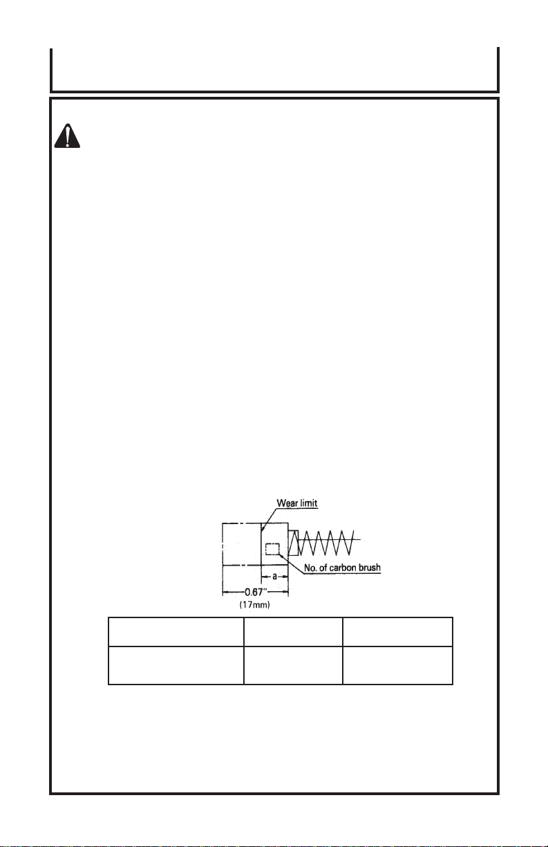
4. Inspecting the carbon brushes:
The motor employs carbon brushes which are consumable parts. When the
brushes are worn down, motor trouble may result. When the brushes are worn
down to the limit line, replace the brushes with new ones. Keep the brushes clean,
so that they smoothly slide into the brush holders.
When replacing the brushes with new ones, be sure to use a pair of brushes for
JOHN DEERE ELECTRIC DRILL ET-3504-J corresponding to the illustrated
number.
Auto-stop carbon brushes automatically cut off the electric circuit, when worn down
to the wear limit. This indicates the replacement time of the brush and prevents
damage of the commutator.
PLUG DURING MAINTENANCE AND INSPECTION.
(Fig. 4)
Usual carbon brush 0.24” (6mm) 43
a carbon brush
Auto-stop carbon brush 0.28” (7mm) 73
SERVICE AND REPAIRS
All quality tools will eventually require servicing or replacement of parts due to wear from
normal use. These operations should ONLY be performed by a John Deere Dealer.
REPLACEMENT PARTS
When servicing use only identical replacement parts.
NOTE: Due to JOHN DEERE’s continuing program of research and development, the
specifications herein are subject to change without prior notice.
No. of
1/2-Inch Drill Operator's Manual 13
Page 14

Notes
14 1/2-Inch Drill Operator's Manual
Page 15

Notes
1/2-Inch Drill Operator's Manual 15
Page 16

#37-0689-090403
16 1/2-Inch Drill Operator's Manual
©
Copyright 2003. John Deere
Manufactured for Deere & Company,
Moline, Illinois 61265
1/2" Drill Operator's Manual
111 Code No. C99110561 N
 Loading...