

Page 1

ET -3407-J 14-INCH
ABRASIVE CHOP SAW
CAUTION
RISK OF INJURY!
THIS MANUAL IS AN IMPORTANT PART OF THE CHOP SAW
AND SHOULD REMAIN WITH THIS UNIT WHEN YOU SELL OR RENT IT.
14-inch Abrasive Chop Saw Operator's Manual 1
READ MANUAL BEFORE OPERATING!
Page 2

Introduction
Congratulations on the purchase of your new Chop Saw! You can be assured your chop
saw was constructed and designed with quality and performance in mind. Each component has been rigorously tested to ensure the highest level of acceptance.
This operator's manual was compiled for your benefit. By reading and following the simple
safety, installation, operation, maintenance and troubleshooting steps described in this
manual, you will receive years of trouble-free operation from your new tool. The contents
of this manual are based on the latest product information available at the time of
publication. The manufacturer reserves the right to make changes in price, color, materials, equipment, specifications or models at any time without notice.
Once the unit has been removed from the box, immediately write in the serial number of your
unit in the space provided below.
SERIAL NUMBER_________________________________
Inspect for signs of obvious or concealed freight damage. If damage does exist, file a claim
with the transportation company immediately. Be sure that all damaged parts are replaced and
that the mechanical problems are corrected prior to operation of the unit. If you require service,
contact your Customer Service.
Mi-T-M® Corporation, 8650 Enterprise Drive, Peosta, IA 52068
1-877-JD-KLEEN / (1-877-535-5336) Fax 563-556-1235
Monday - Friday 8:00 a.m. - 5:00 p.m. CST
Please have the following information available for all service calls:
1. Model Number
2. Serial Number
3. Date and Place of Purchase
WARNING
WEAR RESPIRAT ORY PROTECTION
Some dust created by power sanding, sawing, grinding, drilling and other construction
activities contain chemicals known to the State of California to cause cancer, birth
defects or other reproductive harm. Some examples of these chemicals are:
• Lead from lead-base paints,
• Crystalline Silica from bricks, cement and other masonry products, and
• Arsenic and Chromium from chemically-treated lumber.
Your risk from these exposures varies, depending on how often you do this type of work.
To reduce your exposure to these chemicals, work in a well ventilated area and work
with approved safety equipment, such as those dust masks that are specially designed
to filter out microscopic particles.
2 14-Inch Abrasive Chop Saw Operator's Manual
Page 3

Table of Content
SAFETY .................................................................................................................. 4-8
DESCRIPTION ....................................................................................................... 9
OPERATION........................................................................................................... 10-11
MAINTENANCE AND INSPECTION ..................................................................... 12
NOTES ................................................................................................................... 13-15
GENERAL SAFETY RULES.................................................................. 4-8
MODEL................................................................................................... 9
NAME OF PARTS.................................................................................. 9
SPECIFICATIONS ................................................................................. 9
ASSEMBLY ............................................................................................ 10
OPERATION .......................................................................................... 11
BRUSH INSPECTION AND REPLACEMENT ...................................... 12
STORAGE.............................................................................................. 12
14-inch Abrasive Chop Saw Operator's Manual 3
Page 4
W
ARNI
N
G
W
A
RN
I
NG
SIN
T
HEMA
NUA
LS
.
W
A
RN
I
NG
SIN
T
HEMA
NUA
LS
.
CA
U
T
I
ON
OC
AUT
I
ON
S
IN
O
T
H
E
M
A
N
UA
L
S
OCAUT
I
ON
S
IN
O
T
H
E
M
A
N
UA
L
S
OCAUT
I
ON
S
IN
O
T
H
E
M
A
N
UA
L
S
OC
AUT
I
ON
S
IN
O
T
H
E
M
A
N
UA
L
S
DANGER
WARNING
CAUTION
Safety
RECOGNIZE SAFETY INFORMATION
This is the safety alert symbol. When you see this symbol on
your tool or in this manual, be alert to the potential for
personal injury.
Follow recommended precautions and safe operating
practices.
UNDERSTAND SIGNAL WORDS
A "DANGER, WARNING or CAUTION" safety warning will be
surrounded by a "SAFETY ALERT BOX." This box is used to
designate and emphasize Safety Warnings that must be
followed when operating this tool.
Accompanying the Safety Warnings are "signal words" which
designate the degree or level of hazard seriousness. The
"signal words" used in this manual are as follows:
DANGER: Indicates an imminently hazardous situation
which, if not avoided, WILL result in death or
serious injury.
WARNING: Indicates a potentially hazardous situation
which, if not avoided, COULD result in death or
serious injury.
CAUTION: Indicates a potentially hazardous situation
which, if not avoided MAY result in minor or
moderate injury.
GENERAL SAFETY RULES
WARNING: Read and understand all instructions.
Failure to follow all
instructions listed below, may
result in electric shock, fire and/
or serious personal injury.
SAVE THESE INSTRUCTIONS
4 14-Inch Abrasive Chop Saw Operator's Manual
Page 5
WARNING
KNOW YOU POWER TOOL.
Read and understand the owner's manual and
labels affixed to the tool. Learn its application and
limitations as well as the specific potential hazards
peculiar to this tool.
GROUND ALL TOOLS.
This tool is equipped with an approved 3-conductor
cord and a 3-prong grounding type plug to fit the
proper grounding type receptacle. The green
conductor in the cord is the grounding wire. Never
connect the green wire to a live terminal.
KEEP GUARDS IN PLACE.
Keep all guards in working order, and place
adjustment and alignment.
REMOVE ADJUSTING KEYS AND WRENCHES.
Form a habit of checking to see that keys and
adjusting wrenches are removed from the tool
before turning it on.
KEEP WORK AREA CLEAN.
Cluttered areas and benches invite accidents. Floor
must not be slippery due to wax or sawdust.
AVOID DANGEROUS ENVIRONMENT.
Don't use power tools in damp or wet locations or
expose them to rain. Keep work area well lit. Provide
adequate surrounding work space.
KEEP CHILDREN AWAY.
All visitors should be kept a safe distance from work
area.
MAKE WORKSHOP CHILD PROOF.
When not in use, tools should be stored by
padlocks, master switches, or by removing starter
keys - tools must be kept out of reach of children.
DON'T FORCE TOOL.
It will do the job better and safer at the rate which it
was designed.
USE RIGHT TOOL.
Don't force tool or attachment to do a job it was not
designed for.
14-inch Abrasive Chop Saw Operator's Manual 5
Page 6

WARNING
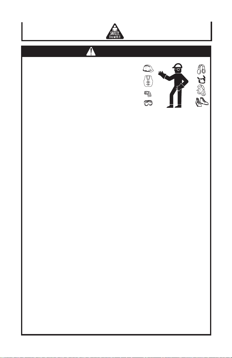
WEAR PROPER APPAREL.
Do not wear loose clothing, gloves, neckties or jewelry (rings, wristwatches) to get
caught in moving parts. NONSLIP footwear is recommended. Wear protective hair
covering to contain long hair. Roll long sleeves above the elbow.
USE SAFETY GOGGLES (HEAD PROTECTION).
Wear safety goggles (must comply with ANSI Z87.1) at all times. "Everyday" eyeglasses only have impact resistant lens, they are NOT safety glasses. Also, use face
or dust mask if cutting operation is dusty, and ear protectors (plugs or muffs) during
extended periods of operation.
DON'T OVERREACH.
Keep proper footing and balance at all times.
MAINTAIN TOOLS WITH CARE.
Keep tools sharp and clean for best and safest performance. Follow instructions for
lubricating and changing accessories.
DISCONNECT TOOLS.
Before servicing: Disconnect tool from power source before changing accessories
such as cutters, etc.
AVOID ACCIDENTAL STARTING.
Make sure the switch is in the "OFF" position before plugging in the power cord.
USE RECOMMENDED ACCESSORIES.
Consult the owner's manual for recommended accessories. Follow the instructions
that accompany the accessories. The use of improper accessories may cause
hazards.
NEVER STAND ON TOOL.
Serious injury could occur if the tool is tipped or if the cutting tool is accidentally
contacted. Do not store materials above or near the tool such that it is necessary to
stand on the tool to reach them.
CHECK DAMAGED PARTS.
Before further use of the tool, a guard or any other part of the tool is damaged, should
be carefully checked to ensure that it will operate properly and perform as its intended
function. Check for alignment of moving parts, binding of moving parts, breakage of
parts, mounting, and any other conditions that may affect its operation. A guard or
other part that is damaged should be properly repaired or replaced.
DIRECTION OF FEED.
Feed work into a blade of cutter against the direction of rotation of the blade or cutter
only.
NEVER LEAVE TOOL RUNNING UNATTENDED.
Turn power OFF. Don't leave tool until it comes to a complete stop.
6 14-Inch Abrasive Chop Saw Operator's Manual
Page 7

CAUTION
1. Wear eye protection.
2. Wear mask or respirator when dust is generated.
3. Tighten cutoff wheel bolt and all clamps before running.
4. Disengage spindle lock before operating.
5. Keep guards in place and working properly.
6. Keep hands clear of cutoff wheel.
7. Never reach behind or beneath the cutoff wheel.
8. Never cut anything free hand.
9. Wait for wheel to stop before moving work piece.
10. Unplug before adjusting or servicing.
11. To avoid electrical shock, do not use under damp conditions or expose to rain.
12. After installing a new replacement wheel, never start the tool with a person in line
with the wheel. Always run the tool for approximately one minute before cutting. If
the wheel has an undetected crack or flaw, it could burst in less than one minute.
13. Use only wheels rated at 3200 RPM or higher.
14. Do not attempt to cut wood, masonry or magnesium with tool.
14-inch Abrasive Chop Saw Operator's Manual 7
Page 8

GROUNDING INSTRUCTIONS:
IMPORTANT
CAUTION: THIS TOOL MUST BE GROUNDED WHILE IN USE TO
In the event of a malfunction or breakdown, grounding provides a path of least
resistance for electric current to reduce the risk of electric shock. This tool is equipped
with an electric cord having an equipment-grounding conductor and a grounding plug.
The plug must be plugged into a matching outlet that is properly installed and
grounded in accordance with all local codes and ordinances.
DO NOT modify the plug provided- if it will not fit the outlet, have the proper outlet
installed by a qualified electrician.
Improper connection of the equipment-grounding conductor can result in risk of
electric shock. The conductor with insulation having an outer surface that is green with
(or without) yellow stripes is the equipment-grounding conductor. If repair or replacement of the electric cord or plug necessary, do not connect the equipment-grounding
conductor to a live terminal.
Check with a qualified electrician or service personnel if the grounding instructions are
not completely understood, or if in doubt as to whether the tool is properly grounded.
Use only 3-wire extension cords that have 3-prong
grounding type plugs and 3-hole receptacles that
accept the tool's plug, as shown.
Repair or replace damaged or worn cord
immediately.
PROTECT THE OPERATOR FROM ELECTRIC SHOCK.
CAUTION: MAKE CERTAIN THE RECEPTACLE
A separate electrical circuit should be used for you tools. This circuit should not be
less that 14 wire and should be protected with a 20 AMP time lag fuse. If an extension
cord is used, use only 3-wire extension cords which have 3-prong grounding type
plugs and 3-pole receptacles which accept the tools plug. For distances up to 100 feet
use 12 wire. For distances up to 150 feet use 10 wire. Have a certified electrician
replace or repair damaged or worn cord immediately. Before connecting the motor to
the power line, make sure the switch is in the "OFF" position and be sure that the
electric current is of the same characteristics as stamped on motor nameplate. All line
connections should make good contact. Running low voltage will damage the motor.
8 14-Inch Abrasive Chop Saw Operator's Manual
IS PROPERLY GROUNDED. IF YOU
ARE NOT SURE, HAVE A CERTIFIED
ELECTRICIAN CHECK THE RECEPTACLE.
Page 9

Description
MODEL:
ET-3407-J 14-INCH ABRASIVE CHOP SAW
NOTE: The information contained in this Instruction Manual is designed to assist you
NEVER operate, or attempt any maintenance on the tool unless you have first read and
understood all safety instructions contained in this manual.
NAME OF PARTS:
in the safe operation and maintenance of the power tool.
Switch
Carry Handle
Blade Guard
Abrasive Wheel
Quick Release Vise
Fence
Steel Base
(Fig. 1)
SPECIFICATIONS:
14-INCH ABRASIVE CHOP SAW ET-3407-J:
Motor 1. 120V / 15 AMP
Blade
Diameter: 14" (355mm)
Arbor: 1" (25.4mm)
Speed: 3,300 RPM
Capacity
Max. Cross Cut: 1. Round: 5" (127mm)
Max. Milter 45°: 1. Round: 4-1/2" (1212mm)
Overall dimensions: 22- 1/16" x 11-1/32" x 17"
(L x W x H) (560 x 280 x 580mm)
Net/Gross weight: 16.2 KGS / 18 KGS
Packing size: 2.46 CUFT
2. 220V / 50 HZ, 7.5 AMP
2. Square: 4" (100mm)
2. Square: 4" (100mm)
14-inch Abrasive Chop Saw Operator's Manual 9
Page 10

Operation
ASSEMBLY:
1. This cut off saw is shipped with the cutting head
locked in the down position.
2. Remove locking chain to have cutting head in
up position.
3. Raise wheel guard, push in spindle lock. (Fig. 2)
4. Use the wrench provided with the saw, to loosen
the hex bolt which serves to hold the cutting
wheel in place. Then remove the outer flange.
(Fig. 3)
5. Install the cutting wheel on the arbor shaft.
6. Reinstall the outer flange, then tighten hex bolt.
7. Make sure the cutting wheel is secured by
turning it with your hands.
Spindle
Lock
(Fig. 2)
(Fig. 3)
10 14-Inch Abrasive Chop Saw Operator's Manual
Page 11

Operation
OPERATION:
1. SWITCH ACTION (Fig. 4):
A lock-on button is provided with your saw.
There are two ways you can operate your saw.
a. Short Periods of Cutting: Press trigger to
start your saw and operate it until you
release the trigger.
b. Long Periods of Cutting: Press trigger to
start your saw and have lock-on button
engaged for continuous operation, press
trigger again to stop your saw.
2. ADJUSTING CUTTING DEPTH OF CUTTING
WHEEL (Fig. 5):
Screw the adjustable screw clockwise, then
secure the bolt by tightening nut for deeper
cutting. for shallow cutting, screw the adjustable
screw counterclockwise.
3. USING CLAMP DEVICE TO SECURE WORK-
PIECE (Fig. 6):
Put work-piece in place and have clutch open,
then push clamp until touching work-piece. Have
clutch engaged and hold clamp handle to secure
work-piece by tightening clamp.
4. ANGLE CUTTING:
Loosen screw as shown in Fig. 7. Then adjust
fence to the required angle. Tighten screw.
Fence can be adjusted backward and forward to
meet your easy cutting.
(Fig. 4)
Screw
Nut
(Fig. 5)
5. SAFETY COVER (Fig. 8):
Always have movable cover in the lower position
for your personal safety.
(Fig. 6)
Screw
(Fig. 7)
(Fig. 8)
14-inch Abrasive Chop Saw Operator's Manual 11
Page 12

Maintenance and Inspection
MAINTENANCE:
BRUSH INSPECTION AND REPLACEMENT:
CAUTION: BEFORE INSPECTING THE
Brush life varies. It depends on the load on the motor.
Check the brushes after the first 50 hours of use for a
new machine or after a new set of brushes has been
installed.
After the first check, examine them after about 10
hours of use until such time that replacement is
necessary.
The brush holders (Fig. 9), are located on the motor
housing opposite each other. Remove and inspect the
carbon or either brush are worn to 3/16" in length or if
either spring or shunt wire are burned or damaged in
any way, replace both brushes.
If the brushes are found serviceable after removing,
reinstall them in the same position as removed.
STORAGE:
For storage, link the chain on the hook as shown in
Fig. 10. (Fig. 10)
BRUSHES, DISCONNECT THE
MACHINE FORM THE POWER
SOURCE.
(Fig. 9)
12 14-Inch Abrasive Chop Saw Operator's Manual
Page 13

Notes
14-inch Abrasive Chop Saw Operator's Manual 13
Page 14

Notes
14 14-Inch Abrasive Chop Saw Operator's Manual
Page 15

Notes
14-inch Abrasive Chop Saw Operator's Manual 15
Page 16

#37-0710-090403
16 14-Inch Abrasive Chop Saw Operator's Manual
©
Copyright 2003. John Deere
Manufactured for Deere & Company
Moline, Illinois 61265
14-INCH ABRASIVE CHOP SAW
 Loading...