

Page 1
JOHN DEERE
AG & TURF DIVISION
GX24537
G2
John Deere Tractors
100 Series
OMGX24537 G2
OPERATOR’S MANUAL
North American Ve rsion
Printed in U.S.A.
Page 2

INTRODUCTION
c WARNING: The Engine Exhaust
from this product conta ins chemicals kno wn
to the State of California to cause cancer,
birth defects or other reproductive harm.
California Proposition 65 Warning
T able of Contents
Introduction................................................................................................ 1
Product Identification.................................................................................1
Safety Labels............................................................................................. 3
Safety ........................................................................................................ 9
Machine Cleanout ................................................................................... 14
Assembly................................................................................................. 16
Operating Controls ..................................................................................18
Operating................................................................................................. 21
Service Intervals...................................................................................... 31
Service Lubrication.................................................................................. 32
Service Engine ........................................................................................33
Service Transmission .............................................................................39
Service Mower.........................................................................................39
Service Electrical..................................................................................... 44
Service Miscellaneous ............................................................................46
Troubleshooting .......................................................................................50
Storage....................................................................................................52
Specifications.......................................................................................... 53
Warranty..................................................................................................55
Index........................................................................................................ 57
Getting Quality Service ........................................................................... 58
Service Record........................................................................................59
Introduction
Thank Yo u for Purchasing a John Deere Product
We appreciate having you as a customer and wish you many years of safe
and sat is fie d us e of you r mac hi ne.
Using Your Operator’s Manual
This manual is an important part of your machine and should remain with
the machine when you sell it.
Reading your operator’s manual will help you and others avoid personal
injury or damage to the machine. Information given in this manual will
provide the operator with the safest and most effective use of the machine.
Knowing how to operate this machine safely and correctly will allow you to
train others who may operate this machine.
This ma nua l and safety si gn s on your mach in e may also be availa ble in
other languages (see your authorized dealer to order).
Sections in your operator’s manual are placed in a specific order to help
you understand all the safety messages and learn the control s so you can
operate this machine safely. You can also use this manual to answer any
specific operating or servicing ques tions.
The machine shown in this manual may differ slightly from your machine,
but will be similar enough to help you understand our instructions.
RIGHT-HAND and LEFT-HAND si des are determined by facing in the
direction the machine w ill travel when going forward. When you see a
broken line (------), the item referred to is hidden from view.
Before delivering this machine, your dealer performed a predelivery
inspection to ensure best performance.
Special Messages
Your manual contains special messages to bring attention to potential
safety concerns, machine damage as well as helpful operating and
servicin g information. Please read all the information carefully to avoid
injury and machine damage .
c CAUTION: Avoid injury! This symbol and text highlight
potential hazards or death to the operator or bystanders that may
occur if the hazards or procedures are ignored.
Original Instruction
All information, illustrations and
specifications in this manual are based on
the latest information at the time of
publicati on. The right is reserved to make
changes at any time without notice.
COPYRIGHT© 2012
John Deere Worldwide Commercial and
Consumer Equipment Division
COPYRIGHT© 2009, 2010, 2011
Deere & Co.
All rights reserved
Previous Editions
IMPORTANT: Avoid damage! This text is used to tell the operator
of actions or conditions that might result in damage to the
machine.
NOTE: General information is given throughout the manual that may
help the operator in the operation or service of the m achine.
Product Identification
Record Identification Numbers
Lawn Tractors
D105, D110, D120, D130, D140, D160, D170
PIN (D400001-) 49 State
PIN (D040001-) California
PIN (D070001-) Australia, Canada , Mexico, ROW.
If you need to contact an Authoriz ed Service Center for information on
servicing, always provide the prod uct model and ide ntification numbers.
You will need to locate the product identification number (PIN) for the
Introduction - 1
Page 3
PRODUCT IDE NTIFICATION
machin e and engine serial number. Record the information in the spaces
prov ided below.
DATE OF PURCHASE:
_________________________________________
DEALER NAME:
_________________________________________
DEALER PHONE:
_________________________________________
PRODUCT IDENTIFICATION NUMBER:
__ __ __ __ __ __ __ __ __ __ __ __ __ __ __ __ __
ENGINE SERIAL NUMBER:
__ __ __ __ __ __ __ __ __ __ __ __ __ __ __ __ __
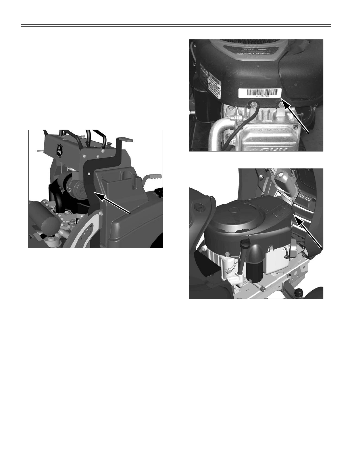
Machine Product Identification Number Location
Engine Seri al Num be r Loca tion
MX25599
Picture Note: Single Cylinder Engines
Picture Note: Located on left side of frame.
MX46486
MX49394
Picture Note: V-Twin Engines
Regist er Your Product and Warranty Onli ne
To register your product through the Internet, simply go to
www.JohnDeereWarrantyRegistration.com. Complet ing the information,
either online or with the product warranty card, will ensure the customer
that their product receives all post sales service and important product
infor mation.
Product Identification - 2
Page 4
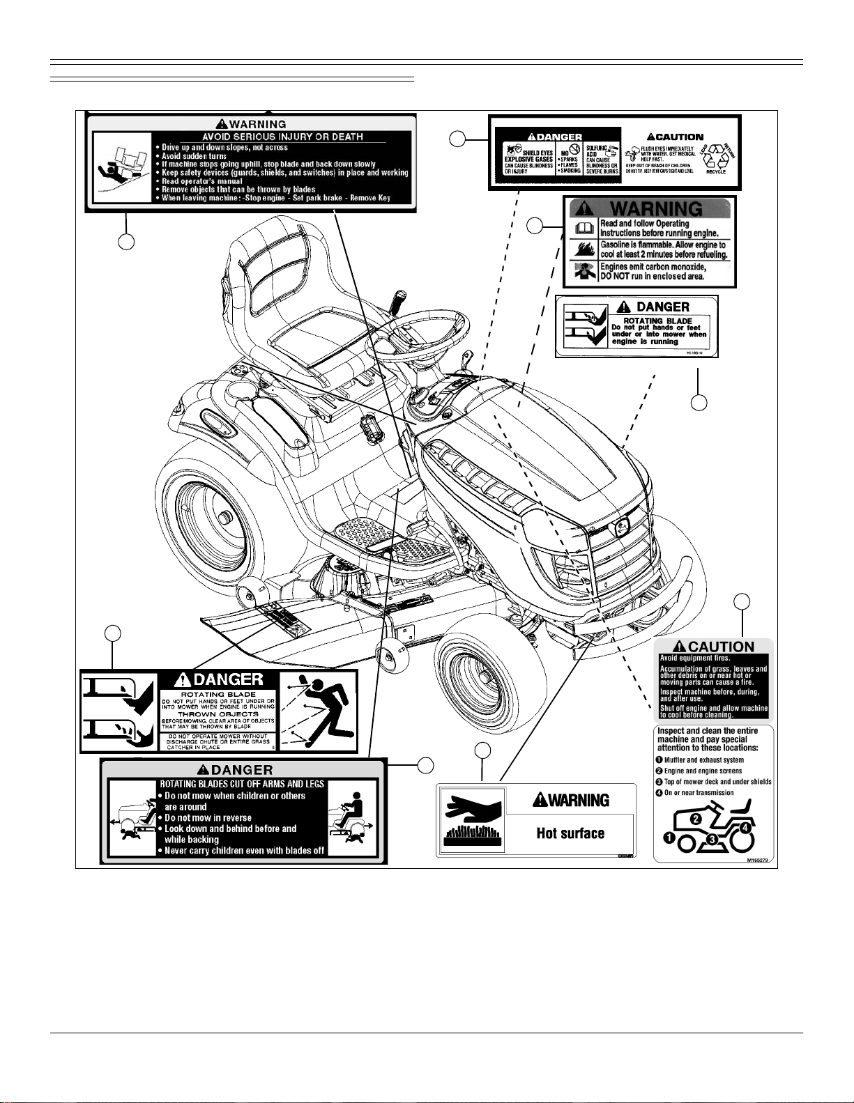
Safety Labels
A
SAFETY LABELS
Safety Label Location (Text)
B
C
D
H
MX46490
Picture Note: Use label number listed in table below to locate
complete text of safety label message following this illustration.
A- WARNING GX22477
B- DANGER/CAUTION M128699
C- W ARNING MX4878
D- DANGER M118610
E- CAUTION M165279
E
F
G
F- WARNING GX23479
G- DANGER GX22477
H- DANGER M89504
Safety Labels - 3
Page 5
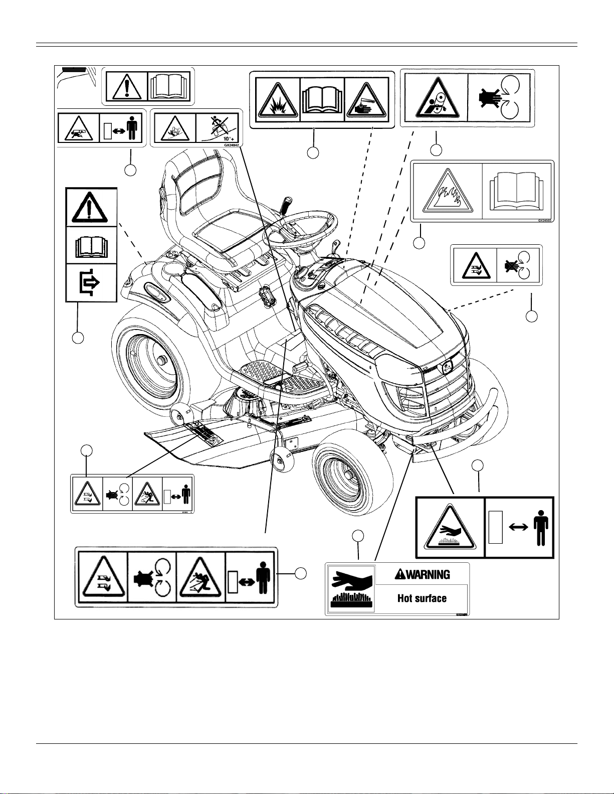
Safety Label Loc a tion (No Text)
SAFETY LABELS
B
A
J
C
D
E
I
MX46490
Picture Note: Non-text labels are required for certain regions of the
world. Your machine may not be equipped with th ese labels. Use
label number listed in table below to locate complete text of safety
label message following this illustration.
A- WARNING GX24842
B- W ARNING M128484
C- W ARNING M136436
D- WARNING GX24503
F
G
H
E- DANGER M118041
F- WARNING GX21121
G- WARNING GX23479
H- DANGER M148522
I - DAN GER M118040
J- WARNING (Bypass Rod) GX21086
Safety Labels - 4
Page 6
SAFETY LABELS
Understanding The Machine Safety Labels
The machine safety labels shown in this section are placed
in impo rtant areas on your machine to draw atte ntion to
potential safety hazards.
On your machine safety labels, the words DANGER,
WARNING, and CA UTION are used with this safety-alert symbol.
DANGER identifies the most serious hazards.
The operator’s manual also explains any potential safety hazards
whenever necessary in special safety messages that are identified with
the word, CAUTION, and the safety-alert symbol.
Warning MX4878
MX4878
• Read and follow Operating Instructions before running engine.
• Gasoline is flammable. Allow engine to cool at l east 2 minutes before
refueling.
• Engines em it carbon mo nox id e, DO NOT ru n in enclosed area.
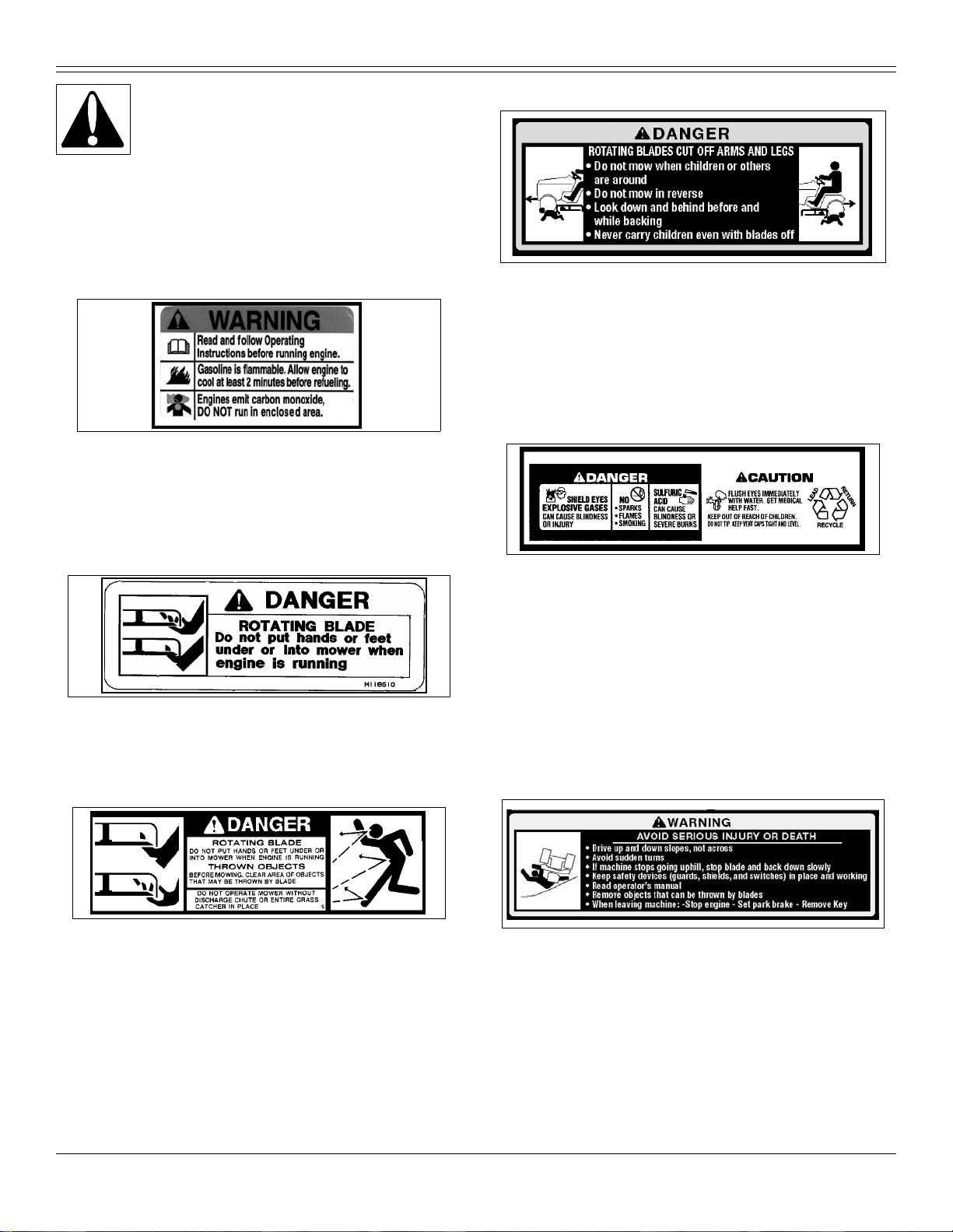
DANGER
GX22477
ROTATING BLADES CUT OFF ARMS AND LEGS
• Do not mow when children or others are around.
• Do not mow in reverse.
• Look down and behind before and wh ile backing.
• Never carry childr en even with blad es off.
DANGER M128699
DANGER
M118610
ROTA TING BL ADE
• Do not put ha nd s or feet und er or into mowe r wh en eng ine is runn in g.
DANGER - M89504
M89504
ROTA TING BL ADE
• Do not put ha nd s or feet und er or into mowe r wh en eng ine is runn in g.
THROWN OB JECTS
• Before mowing, clear area of objects that may be thrown by blade.
• Do not operate mower without discharge chute or entire grass catcher in
place.
M128699
Picture Note: Located on battery
• Shield eyes, explosive gases can cause blindness or injury.
• No sparks, flames, smoking.
• Sulfuric acid can cause blindness or severe burns.
• Flush eyes immediately with water. Get medical help fast.
• Kee p out of reach of children.
• Do not tip.
• Keep vent caps tight and level.
WARNING
GX22477
AVOID SERIOUS INJURY OR DEATH
• Drive up and down slopes, not across.
• Avoid sudden turns.
• If machine stops going u phill, stop blades and back d own slowly.
• Keep safety devices (guards, shields, and switches) in place and
working.
• Remove objects that could be thrown by blades.
• Read operator’s manual.
Safety Labels - 5
Page 7
SAFETY LABELS
• Remove objects th at can be thrown by blades
• When leaving machine:
–Stop engine
–Set par k brake
–Remove key
DANGER GX23479
WARNING
• Hot sur face
Warning M159705
Prevent Equipment Fires
GX23479
M159705
Picture Note: This label is required and installed on machines sold
in California. This label may also be installed on machines sold in
other locations.
Oper ation of This Equipment May Create Sparks that Can Start Fires
Around Dry Vegetatio n. A Spark Arrestor May be Requ ired. The Operator
Should Contact Local Fire Agencies For La ws or Regulations Relating to
Fire Prevention Requirements.
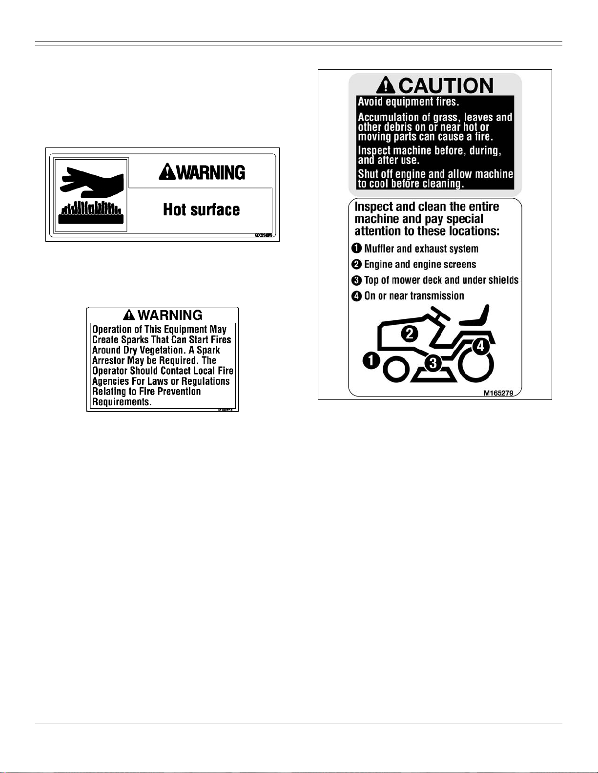
M165279
• Avoid equipment fires.
• Accumulation of grass, leaves and other debris on or n ear hot or moving
parts can cause a fire.
• Inspect machine before, during, and after use.
• Shut off engine and allow machine to cool before cleaning.
Inspect and clean the entire machine and pay special attention to these lo c ations:
1. Muffler and exhaust system
2. Engine and engine screens
3. Top of mower deck and un der shields
4. On or near transmission
Emission Control System Certification Label
NOTE: Tampering with emission controls and components by
unauthorized personnel may result in severe fines or penalties.
Emission controls and components can only be adjusted by EPA
and/or CARB authorized service centers. Contact your John Deere
Retailer concerning emission controls and component questions.
The presence of an emissions label signifies that the engine has been
certified with the United States Environmental Protection Agency (EPA)
and/or California Air Resources Board (CARB).
The emis sions warranty applies only to those engines marketed by John
Deere that have been certified by the EPA and/or CARB; and used in the
United States and Can ada in off-road mobil e equipment.
Safety Labels - 6
Page 8
SAFETY LABELS
Emission Compliance Period
If your engine has the emission compliance category listed on the
emissio n control sy s tem ce rtific a tion or air index la be l, thi s in dic a t es the
number of operating hours for which the engine has been certified to meet
EPA and/or CARB emission requirements. The following table provides
the engine compliance period in hours associated with the category found
on the cer tifica tio n label.
Agency Category Hours
EPA C 250
EPA B 500
EPA A 1000
CARB Moderate 125
CARB Intermediate 250
CARB Extended 500
Certification
Your mo wer has been certified for compliance with American National
Standards Institute B-71.1-2003, “Safety Specifications” for Power Lawn
Mowers, Lawn and Garden Tractors, and Lawn Tractors.
Canadian Electromagnetic Compatibility (EMC) Compliance
This spark ignition system complies with Canadian ICES-002.
Pictoria l Safety Signs
At several imp ortan t pl a c es on t hi s ma ch ine safety signs
are affixed intended to signify potential danger. The hazard
is iden tif i ed b y a pi ctor ia l in a w a rnin g tria ng l e. An ad ja ce nt
pictorial provides information how to avoid personal injury.
These sa fety signs, the ir pl ac em e nt on the ma ch ine and a bri ef
explanatory text are shown in this Safety section.
There can be additional safety information contained on parts and
components sourced from suppliers that is not reproduced in this
operator’s manual.
Avoid In jury From Rotating Blades - M118041
M118041
• Do not put hands or feet under or into mower when eng ine is running.
• Do not operate mower without discharge chute or entire grass catcher in
place.
WARNING M128484
M128484
Avoid Injury From Battery Gases and Acids
• Batteri es conta in e xp losi v e ga se s an d sulf ur ic acid. Us e ex tr em e caut i on
when handling battery.
• Read operator’s manual for all safety informa tion before handling battery.
• Use extreme caution when handling battery.
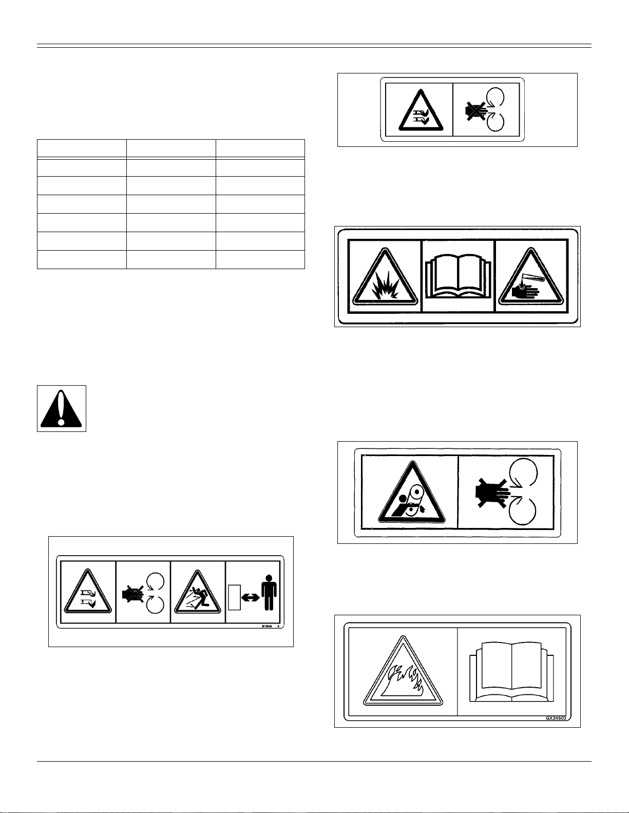
Avoid In jury From Getting Caught in Belt - M136436
Av oi d Inju ry Fr om Rot ati ng Bl ades and Thr own Objec ts
- M118040
M118040
• Do not put ha nd s or feet und er or into mowe r wh en eng ine is runn in g.
• Do not operate mower without discharge chute or entire grass catcher in
place.
• Before mowing, clear area of objects that may be thrown by blade.
• Stay clear wh ile engine is runn in g.
Safety Labels - 7
M136436
• Stay clear of belts.
• Do not oper at e mow e r wit ho ut sh ields in plac e.
WARNING GX24503
GX24503
Page 9
SAFETY LABELS
Clean and inspect the entire machine.
Carefully read Operator’s Manual Machine Cleanout section for details.
WARNING GX21121
GX21121
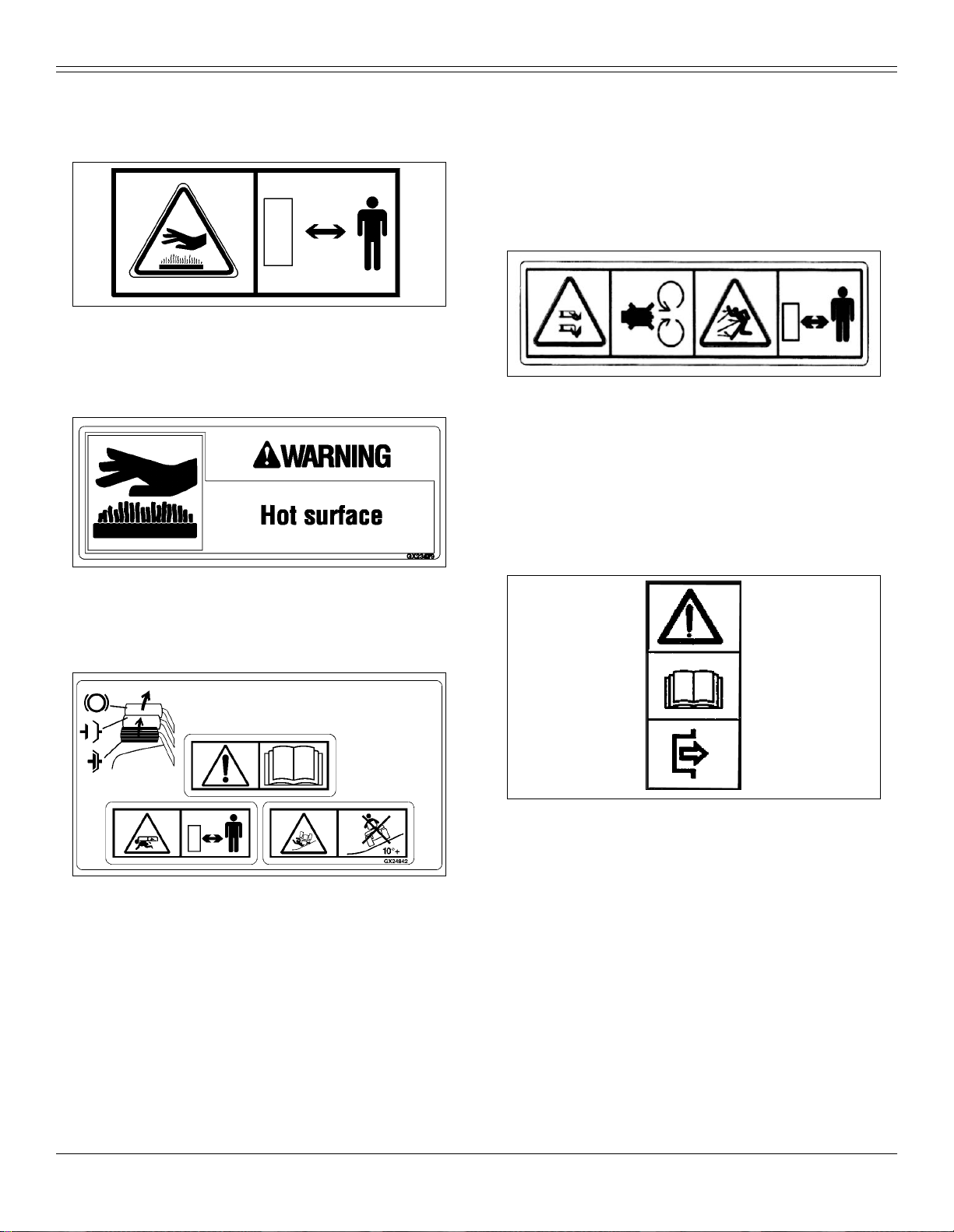
Warning - Hot Surfaces
• Ke ep away from hot surfaces.
WARNING - GX23479
Avoid Injury From Tipping
• In some co nfigurations, do not drive or operate on a slope of more than
10 degree s.
• Refer to the Operating on Slopes section for more information.
• Drive up and down slopes, not across.
• Avoid sudden turns.
Avoid Injury From Rotating Blades and Thrown Objects
M148522
• Do not put hands or feet under or into mower when eng ine is running.
• Keep away from rotating parts. Do not open or remove safety shields
while engine is runnin g.
• Thrown O bjects - Before mowing, clear area of objects t hat may be
thrown by blade. Do not operate mower without discharge chute or entire
grass catcher in place.
• Stay a safe distance from machine.
GX23479
WARNING
• Hot sur face
Avoid Inju ry
GX24842
Picture Note: Located on fenderdeck in front of seat.
Read Operators Manual
• This operator’s manual contains important information necessary for safe
machine operation. Observe all safety warnings to avoid accidents.
Keep Children Away From Mower
• Do not mow when children or others are around.
• Do not mow in reverse.
• Look down and behind before and while backing.
• Never carry children even with blades off.
Avoid Injury: Use Transmission Bypass Rod Safely
GX21086
• Carefully read operator’s manual for safe operation of transmission
bypass rod.
Safety Labels - 8
Page 10

SAFETY
Safety
Operating Safely
This cutting machine is capable of amp utating hands and
feet and throwing objects. Failure to observe the following
safety instructions could result in serious injury or death.
• Read, understand and follow all instructions on the
machine and in manuals provided, and view safety video, before starting.
Be thoroughly familiar with the controls and the proper use of the machine
before starting.
• Do not put hands or feet near rotating parts or under the machine. Keep
clear of the discharge opening at all times.
• Only allow responsible adults, who are familiar with the instructions, to
operate this machine. Local regulations may restrict the age of the
operator.
• Clear the area of objects such as rocks, wire and toys which could be
thrown by the blades.
• Be sure the area is clear of bystanders befor e operating. Stop machine if
anyone enters the area.
• Never carry passengers.
• Do not mow in reverse unless absolutely necessary. Always look down
and behi nd befor e an d wh il e ba cki ng.
• Never direct discharged material toward anyone. Avoid discharging
material against a wall or obstruction. Material may ricochet back toward
the operator. Stop the blades when crossing gravel surfaces.
• Do not operate the machine without the entire grasscatcher, discharge
guard, or other safety devic es in place and wo rking. Never operate with
the discharge deflector raised, removed, or altered, unless using a
grasscatcher.
• Slow down before t u rn ing.
• Never leave a running machine unattended. Always turn off blades, lock
park brake, stop engine and remove key before dismounting.
• Disengage blades when not mowing. Shut off engine and wait for all
parts to com e to a complete stop before cleaning the machine, removing
the grasscatcher, or unclogging the discharge chute.
• Operate machine only in daylight or good artificial light.
• Do not operate the machine while under the influence of alcohol or
drugs.
• Watch for traffic when operating near or crossing roadways. Stop blades
before crossing ro ads or sidewal k s.
• Use extra care whe n loading or unloading the machine into a trailer or
truck.
• Always wear safety goggles or safety glasses with side shields when
operating machin e.
• Data indicates operators 60 year s and above ar e involved in a large
percentage of riding mower-related injuries. These operators should
evaluate their ability to operate the riding mower safely enough to protect
themselves and others from serious injury.
• Follow the manufacturer’s recommendation for wheel weights or
counterweights.
• Inspect machine before you operate. Be sure hardware is tight. Repair or
replace damaged, badly worn, or missing parts. Be sure guards and
shields are in good condition and fastened in place. Make any necessary
adjust me nts before yo u op erate.
• Before using, always visually inspect to see that the blades, blade bolts
and the m ower assembly are not worn and damaged. Replace worn and
damaged blades and bolts in sets to preserve balance.
• Make sure spark plug, m uffler, fu el cap and air cleaner are in place
before starting the engine.
• Be sure all drives are in neutral and parking brake is locked before
starting engine. Only st art engine from the operator’s position.
• Do not change the engine governor settings or overspeed the engine.
Operating the engine at excessive speed can increase the hazard of
person al injury.
• If y ou hit an object or if abnormal vibration occurs, stop the machine and
inspect it. Make repairs before you operate.
• Use only accessories and attachments approved by the manufacturer of
the machine. Keep safety labels visible when installing accessories and
attachments.
• Do not wear radio or music head ph on es. Safe service and operation
requires your full attention.
• When machine is left unattended, stored, or parked, lower the mower
deck unless a positive mechanical lock is used.
Using a Spark Arrestor
The California Public Resources Code, section 4442.5 provides as
follows:
No person shall sell, offer for sale, lease, or rent to any person any internal
combustion engine subject to Section 4442 or 4443, and not subject to
Section 13005 of the Health and Safety Code, unless the person provides
a written n ot ic e to t he pu rcha se r o r bai l ee , at th e tim e of sa le or at the t i me
of entering into the lease or rental contract, stating that it is a violation of
Section 4442 or 4443 to use or operate the en gine on any f orest-covered,
brush-covered, or grass-cov ered land unless the engine is eq uipped with
a spark arrestor, as defined in Section 4442, maintained in effective
working order or the engine is constructed, equipped, and maintained for
the prevention of fire pursuant to Section 4443. Cal. Pub. Res. Code
4442.5.
Other states or jurisdictions may have similar laws. A spark arre stor for
your m achine may be available from your auth orized dealer. An installed
spark arrestor must be maintained in good working order by the operator.
Checking Mowing Area
• Clear mowing area of objects that might be
throw n. Keep people and pets out of mowing
area.
• Low-hanging branches and similar obstacles
can injure the operator or interfere with
mowing operation. Before mowing, identify potential obstacles such as
low-hanging branch es, and trim or r emove those obstacles.
• Study mowing area. Set up a safe mowing pattern. Do not mow where
traction or stability is doubtful.
• Test drive area with mower lowered but not running. Slow down when
you travel over rough ground.
Parking Safely
1. Stop machine on a level surface, not on a slope.
2. Disengage mower blades or any other attachments.
3. Lower attachments to the ground.
4. Lock the park brake.
5. Stop the engine.
6. Remove the key.
Safety - 9
Page 11
SAFETY
7. Wait for engine and all moving parts to stop before you leave the
operator’s seat.
8. Close fuel shut-of f valve, if your machine is equipped.
9. Disconnect the negative battery cable or remove the spark plug wire(s)
(for gasoline engines) before servicing the mac hine.
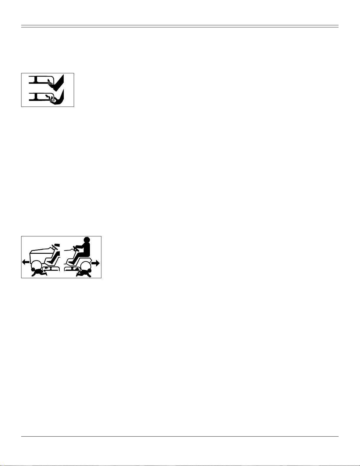
Rotating Blades are Dangerous
HELP PREVENT SERIOU S OR FATAL ACCIDENTS:
• Rotating blades can cut off arms and legs,
and throw objects. Failure to observe safety
instructions could result in serious injury or
death.
• Keep hands, feet and clothing away from mower deck when engine is
running.
• Be alert at all times, drive forward and in reverse carefully. People,
especially children can move quickly into the mowing area before you
know it.
• Before backing up, stop mower blades or attachments and look down
and behind the machine carefully, especially for children.
• Do not mow in reverse.
• Shut off blades when you are not m owing.
• Park machi ne safely before leaving the operator’s station for any reason
including emptying the grasscatchers or unplugging the chute.
• The mo wer blades should stop in appr oximately f ive seconds when the
mower is disengaged. If you believe that your blades may not be stopping
in that period of time, take your machine to your authorized dealer where
they can safely check and service yo ur machine.
Protect Children
• Death or se rious injury ca n
occur when young children
associate having fun with a lawn
mowing machine simply because
someone has given them a ride
on a machine.
• Children are attracted to lawn mowing machines and mowing act ivities.
They don’t understand the dangers of rotating blades or the fact that the
operator is unaware of their presence.
• Children who have been given rides in the past may su ddenly appear in
the mo wing area for another ride and be run over or backed over by the
machine.
• Tragic accidents with children can occur if the operator is not alert to the
presence of children, especially when a child approaches a machine from
behind . B efore and while ba cking up, stop mo we r blades and look down
and behind the machine carefully, especially for children.
• Never carry children on a machine or attachment, even with the blades
off. Do no t t ow c hi ldr en in a cart or t r a ile r. They ca n f al l of f an d b e s er ious ly
injured or interfere with safe machine operation.
• Never use the machine as a recreational vehicle or to entertain children.
• Never allow chil dr e n or an untraine d pe r so n op er a te the machin e.
Instruct all operat ors not to give children a ride on the machine or in an
attachment.
• Ke ep chi l dr en in do or s , out of the mo w ing ar ea , and in t he wat ch ful e y e of
a responsible adult, other than the operator, when a mower is being
operated.
• Stay alert to the presence of children. Never assume that children will
remain where you last saw them. Turn the machine off if a child enters the
work area.
• Use ex treme care when approaching b lind corners, shrubs, trees, or
other objects that may block your view of a child.
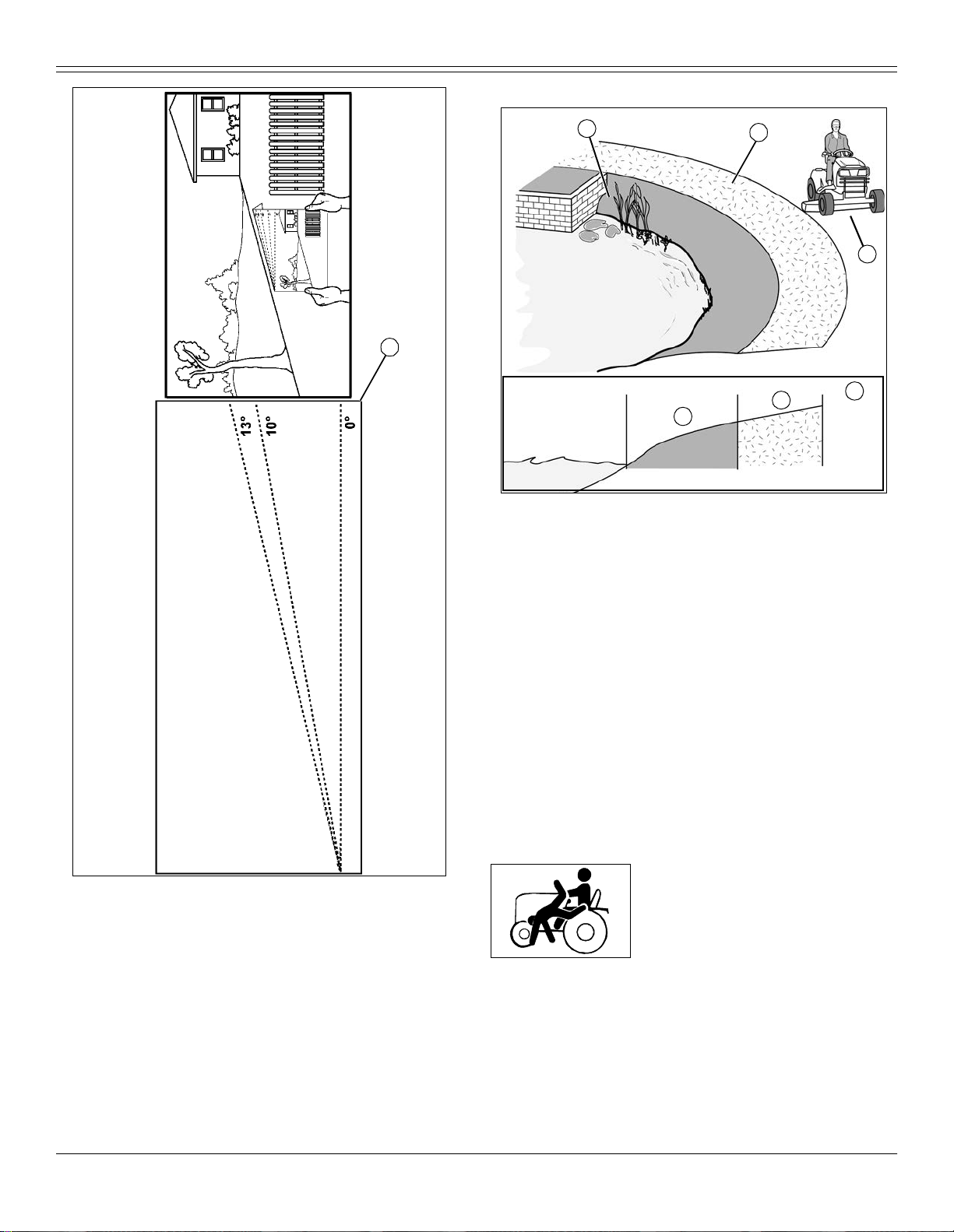
Operating on Slopes
NOTE: Make a photocopy of this page and cut out angle chart (A) to
use for measuring slope angle.
• Slopes ar e a maj or factor relate d t o l oss -of -co nt rol an d t ipo v er ac cide nt s ,
which can result in severe injury or death. Operation on all slopes requires
extra caution.
Identify Slopes for Safe Operation
• Follow safe procedures for operation on slopes. Measure slopes of all
moving sites to determine which slopes are safe for mowing with a ride-on
mower. Always use common sense and good judgement when performing
this survey.
Measuring Slopes
• Sugges ted Method 1: Lay a straight piece of sturdy lumber 1.2 m (4 ft)
long on the slope and measu re the angle of the slope with an angle
indica tor or protract or level.
• Suggested Method 2: Refer to the slope gauge provided with this
manual.
Operate Safely on Slopes
• Exceeding the recommended maximum slope angle increases the risk of
rollover accidents that can result in serious injury or death.
• Nev er mow or operate ride-on mower on slope angles greater than 13°
with the lawn ride-on mower in its basic configuration. The basic
configuration is the ride-on mower with mower deck and not other
attachments. (A 13° slope is a slope tha t rises 1.4 m (4.6 ft) over a
horizontal distance of 6.1 m (20 ft).)
• When us in g att a c hm en ts, never mow or operate the rid e -o n mow e r on
slope ang le s grea t e r th an 10° . Th e ad di tio n of a weather enc lo su re,
material collection system, or other attachments will increase the risk of a
rollover. (A 10° slope is a slop e that rises 1 m (3.5 ft) over a horizontal
distance of 6.1 m (20 ft).)
• On slope angles of 10° or less, the risk of rollover is low, but as the slope
angle increases to the recommended maxim um, the risk increases to a
medium level.
• Always consider potential turf conditions and slope angles when
determining the risk of loss-of-control and tip-ov er accidents.
• Drive slowly when mowing or operating on slopes.
• If you feel uneasy on a hillside, do not mow or operate on it.
• Mow up and down slopes, not across.
• Watch for holes, ruts, bumps, rocks, or other hidden objects. Uneven
terrain could overturn the ride-on mower. Tall grass can hide obstacles.
• Drive slowly so you will not have to stop while on a slope.
• Do not mow on wet grass. Tires may lose traction. Tires may slip on
slopes even though the brakes are func tioning properly.
• Avoid starting, stopping or turning on a slope. If the tires lose traction,
diseng age the PTO and proceed slowly, straight down the slope.
• Keep all movement on slopes slow and gradual. Do not make sudden
changes in spee d or dir e ctio n, whi ch co ul d caus e t he ride - on mo w er to r ol l
over.
Safe ty - 10
Page 12
SAFETY
Operating Near Hazards
A
A
A
Picture Note: Example side view of slope and hazards, showing
areas (A), (B), and (C).
• Do not mow or operate ma chine in areas adjacent to haza r d s that may
cause the machine to roll over. The machine could suddenly lose traction,
slide, and/or roll over if a wheel goes over the edge or if the edge breaks
away.
• Hazards (A) include but are not limited to:
• Drop-offs, ditches, embankments, or bodies of water.
• Areas of unsafe slope, soft ground, edges along bodies of water, or
area with holes, ruts, bumps, or other hidden objects.
• Maint ain a buffer area (B) at least as wid e as the machine between
hazards ( A) an d the mo win g a rea (C) . D o not mo w or o per ate th e ma ch ine
in the hazard area or buffer area.
• Only mow or operate the machine in the mowing area (C). Do not exceed
the recommended slope operating angle. Refer to the "Operate Safely on
Slopes" section.
• Use a walk-behind mower or string trimmer in and around areas (A) and
(B).
B
C
B
C
MX51888
MX51667
Keep Riders Off
• Only allo w the op er ator on the mach ine . Ke ep
riders off.
• Riders on the machine or attachment may be
struck by foreign objects or thrown off the
mach in e ca us in g seriou s in jury.
• Riders obstruct the operator’s view resulting in the machine being
operated in an unsafe manne r.
Tow ing Loads S afely
• Stopping distance increases with speed and weight of towed load. Travel
slowly and allow extra time and distance to stop.
• T otal towed weight must not exceed combined weight of pulling machine,
ballas t an d o pe rat o r . Use co un ter we ig ht s or whe el we ig ht s as de scr ibed i n
Safe ty - 11
Page 13

SAFETY
the attachment or pulling machine operator’s manual.
• Excessive towed load can cause loss of traction an d loss of control on
slopes. Reduce towed weight when operating on slopes.
• Never allow children or others in or on tow ed equipment.
• Use on ly approved hitches. Tow only with a machine that has a hitch
designed for towing. Do not attach towed equipment except at the
approved hi t ch poi nt.
• Follow the manufacturer’s recommendations for weight limits for towed
equipment and towing on slopes.
• Towed attachments will increase the risk of rollover. Refer to the
“Operating on Slopes” section for more information.
• Do not turn sharply. Use additional caution when turning or operating
under adverse surface conditions. Use care when reversing.
• Do not shift to neutral and coast downhill.
Wear Appropriate Clothing
• Always wear eye protection when operating
the machine.
• Wear close fitting cl oth in g and safety
equipment appropriate for the job.
• Whil e oper a tin g t hi s mac hi ne, al ways wear subs ta nti al f oot we ar an d l ong
trousers. Do not ope rate the equipment when barefoot or wearing open
sandals.
• Wea r a suitable protective device such as earplugs. Loud noise can
cause impairment or loss of hearing.
Driving Safely on Public Roads
Avoid personal injury or death resulting from a
collision with another vehicle on public roads:
• Use safety lights and devices. S low moving
machin es when driven on public roads are
hard to see, especially at night.
• Whenever driving on public roads, use flashing warning lights and turn
signals according to local regulations. Extra flashing warning lights may
need to be installed.
Practice Safe Maintenance
• Only qualified, trained adults should service
this machine. Understand service procedure
before doing work.
• Never operate machine in a closed area
where dangerous carbon monox ide fumes can collect.
• Keep all nuts and bolts tight, especially blade attachment bolts, to be
sure the equipment is in safe working condition.
• Never tamper wit h safety devices. Check their proper operation r egularly.
• Keep machine free of grass, leaves or other debris build-up. Clean up oil
or fuel spillage and remove any fuel-soaked debris. Allow the machine to
cool before storing.
• If you strike a foreign object, stop and inspect the machine. Repair, if
necessary, before restarting.
• Never make any adjustments or repairs with the engine running. Wait for
all mo vement to stop on machine bef ore adjusting, cleaning or r epairing.
• Check grasscatcher components and the discharge guard frequently and
replace with manuf acturer’s recommended parts, when necessary.
Grass ca tche r co mpo nent s ar e subjec t to wea r , dam ag e , and de te rioration
which could expose moving parts or allow objects to be thrown.
• Mower blades are sharp. Wrap the blade or wear gloves, and use extra
care when servicing them. Only replace blades. Never straighten or weld
them.
• Chec k brake operation frequently. Adjust and servic e as required.
• Maintain or replace safety and instruction labels, as necessary.
• On multi-bladed machines, take care as rotating one blade can cause
other blades to rotate.
• Keep hands, feet, clothing, jewelry, and long hair away from any moving
parts, to prevent them from getting caught.
• Lower any attachments to the ground before cleaning or servicing
machine. Disengage all power and stop th e engine. Lock park brake and
remove the key. Let machine cool.
• Securely support any machine elements that must be raised for service
work. Use jack stands or lock service latches to support components
when needed.
• Disconnect battery or remove spark plug wire (for gasoline engines)
before making any repairs. Disconnect negative terminal first and positive
last. Install positive terminal first and negative last.
• Before servicing machine or attachment, carefully release pressure from
any components with stored energy, such as hydraulic components or
springs.
• Keep all parts in good condition and properly installed. Fix damage
immediately. Replace wo rn or broken parts.
• Charge batteri es i n an op en , we ll-ventila te d area, away from sparks.
Unplug battery charger be fore connecting or disconnecting from the
battery. Wear protectiv e clothing and u s e insulated tools.
• Do not str ike the flywheel with a hammer or hard object be cause the
flywheel may later shatter during operation.
• If equipped with hydraulic lift - release hydraulic pressure by lowering
attachment or cutting units to the ground or to a mechanical stop and
move hydraulic control levers back and forth.
Avoid High Pressure Fluids
• Hydraulic hoses and lines can fail due to
physi cal damage, kinks, age, and exposure.
Check hoses and lines regularly. Replace
damaged hoses and line s.
• Hydraulic fluid connections can loosen due to physical damage and
vibration. Check connections regularly. Tighten loose connections.
• Escaping fluid under pr essure can penetrate the skin causing serious
injury. Avoid the hazard by relieving pressure before disconne cting
hydraulic or other lines. Tighten all connections before applying pressure.
• Search for leaks with a piece of cardboard. Protect hands a nd body from
high pressure fluids.
• If an accident occurs, see a doctor immediately. Any fluid injected into
the skin must be surgically removed within a few hours or gangrene may
result. Doctors unfamiliar with this type of injury s hould refere nce a
knowled g ea ble me dical sourc e. S uc h inform a tion is available from D ee r e
& Company Medical Department in Moline, Illinois, U.S.A. Information may
be obta ined in the United States and Canada only by calling 1-800-822-
8262.
Safe ty - 12
Page 14
SAFETY
Prevent Fires
• Besides routine maintenance, one of the best
ways to keep your John Deere equipment
running efficiently and to reduce fire risk is to
regularly remove debris buildup from the
machine.
• Please review these recommendations with all
operators. See your John Deere dealer with
questions.
• Always follow all safety procedures posted on the machine and in this
operator manual. Before carrying out any inspection or cleaning, always
shut off engine, set parking brak e and remove ignition key.
• After op era ti n g, all o w mac hi ne to coo l in an ope n ar ea be fore cleanin g or
storing. Do not park machine near flammable materials such as wood,
cloth or chemicals.
• Empty any grasscatcher bags or containers completely before storing.
• Frequency of thes e inspect i on s an d cleanin g will vary de pe nd ing on a
number of factors incl ud in g operatin g co nd it i on s, ma chine configurat ion,
operating speeds and weather con ditions particularly dry, hot and windy
conditions. When you are operating in these conditions, inspect and cl ean
these areas frequently throughout the day.
• Wind direction, terrain type and moisture content of surrounding
vegetation can effect where and how much debris accumulates.
• Debris can accumulate anywhere on the machine, especially on
horizontal surfaces.
• Ke eping engine ar ea clean will provide the greatest impact on fire
prevention. Other are as re qu iring reg ul ar ins p ec t io n an d cl eaning include
behind wheel rims, wire harness, hose/line routings, mowing attachments,
etc. Compressed air, leaf blowers or high pressured water can assist
keeping these areas clean.
• Excess lubrication or fuel/oil leaks or spills on the machine can also
serve as collection sites for debris. Prompt machine repair and oil/fuel
cleanup will minimize the potential for debris collection and reduced
cooling throughout machine life.
• Bearing failures or overheating can result in a fire. To reduc e this risk,
always follow the instructions in the machine operator’s manual regarding
lubrication intervals and locations. Washing the machine while warm may
also reduce bearing life and increase potential for premature bearing
failure.
• Always shut off fuel when storing or transpo rting machine, if the machine
has a fuel sh utoff.
Handling Fuel Safely
To avoid personal injury or property
dama ge, use extre me care in handling fuel.
Fuel is extremely flam m able and fue l
vapors are explosive:
• Extinguish all cigarettes, cigars, pipes, and
other sources of ignition.
• Use only an approved fuel co nt ainer. Use
only non-metal, portable fuel containers
approved by the Underwriter’s Laboratory
(U.L.) or the American Society for Testing &
Materials (ASTM). If using a funnel, make sure
it is plastic and has no screen or filter.
• Never remove the fuel tank cap or add fuel with the engine running. Allow
engine to cool before refueling.
• Never add fuel to or drain fuel from the machine indoors. Move machine
outdoo rs and provid e adequate ventilation.
• Clean up spilled fuel immediately. If fuel is spilled on clothing, change
clothing immediately. If fuel is spilled near machine, do not attempt to start
the engine but move the machine away from the area of spillage. Avoid
creating any source of ignition until fuel vapors have dissipated.
• Nev er store the machine or fuel container where there is an open flame ,
spark, or pilot light such as on a water heater or other appliance.
• Prevent fire and explosion caused by static electric di scharge. Static
electric discharge can ignite fuel v apors in an ung rounded fuel c ontainer.
• Nev er fill containers inside a vehicle or on a truck or tra iler bed with a
plasti c liner. Always place containers on the ground away from your
vehicle before fueling.
• Remove fuel-powered equipment from the truck or trailer and refuel it on
the ground. If this is not possible, then refuel such equipment with a
portable container, rather than from a fuel dispenser nozzle.
• Keep the nozzle in contact with the rim of the fuel tank or container
opening at all times until the fuel ing is complete. Do not use a nozzle lockopen devi ce.
• Never overfill fuel tank. Replace fuel tank cap and tighten securely.
• Replace all fuel container caps securely after use.
• For gasoline engines, do not use gas with methanol. Methanol is harmful
to your health and to the en vi ronment .
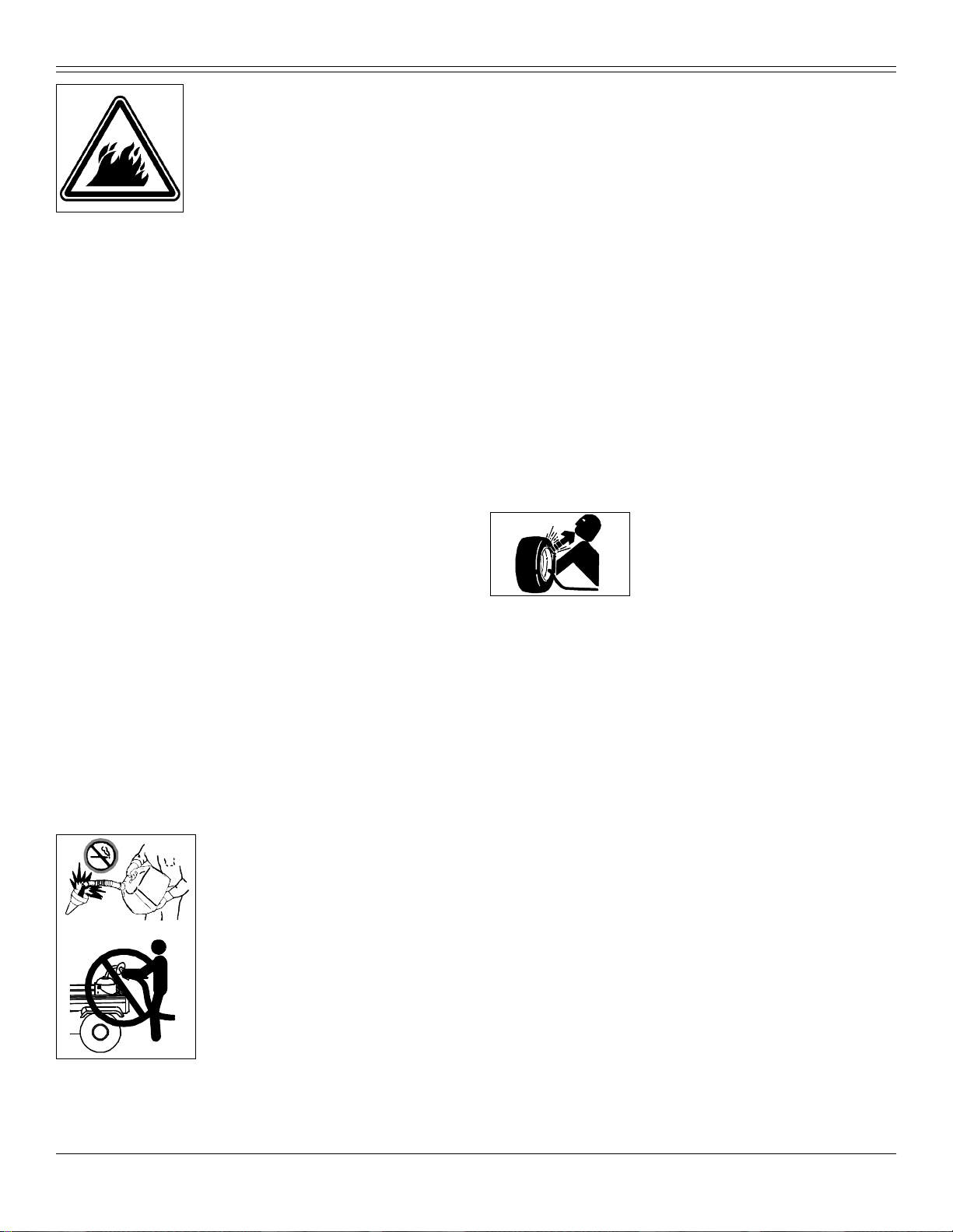
Tire Safety
Explos ive separation of a tire and rim parts
can cause serious injury or death:
• Do not attempt to mount a tire without the
proper equipment and experience to perform
the job.
• Always maintain the correct tire pressure. Do not inflate the tires above
the recommended pressure. Never weld or heat a wheel and tire
assembly. The heat can cause an increase in air pressure resulting in a
tire explosion. Welding can structurally weaken or deform the wheel.
• When i nfl at i ng ti r es, u se a cl i p-o n c huc k an d e xt e nsi on hose l on g e noug h
to allow you to stand to one side and NOT in front of or over the tire
assembly.
• Check tires for low pressure, cuts, bubbles, damaged rims or missing lug
bolts and nuts.
Checking Wheel Hardware
• A serious accident could occur causing serious injury if wheel hardware
is not tight.
• Check wheel hardware tightness often during the first 100 hours of
operation.
• Wheel hardware must be tightened to specified torque using the proper
procedure anytime i t is loosened.
Handling Waste Product and Chemicals
Waste products, such as, used oil, fuel, coolant, brake fluid, and batteries,
can harm the environment and people:
• Do not use beverage containers for waste fluids - someone may drink
from them.
• See your local Recycling Center or authorized dealer to learn how to
recycle or get rid of waste products.
• A Material Safety Data Sheet (MSDS) provides specific details on
chemical products: physical and health hazards, safety procedures, and
Safe ty - 13
Page 15
MAC HINE CLEANOUT
emergency response techniques. The seller of the chemical products
used with you r mac h in e is res ponsible for prov iding the MSDS for that
product.
A
Machine Cleanout
Prevent Fires
• Besides routine maintenance, one of the best ways to keep your John
Deere equipment running efficiently and to reduce fire risk is to regularly
remove debris buildup from the machine.
• Please review these recommendations with all operators. See your John
Deere de al er wit h que st ions.
• Always follow all safety procedures posted on the machine and in this
operator manual. Before carrying out any inspection or cleaning, always
shut off engine, set parking brak e and remove ignition key.
• After op era ti n g, all o w mac hi ne to coo l in an ope n ar ea be fore cleanin g or
storing. Do not park machine near flammable materials such as wood,
cloth or chemicals.
• Empty any grasscatcher bags or containers completely before storing.
• Frequency of thes e inspect i on s an d cleanin g will vary de pe nd ing on a
number of factors incl ud in g operatin g co nd it i on s, ma chine configurat ion,
operating speeds and weather con ditions particularly dry, hot and windy
conditions. When you are operating in these conditions, inspect and cl ean
these areas frequently throughout the day.
• Wind direction, terrain type and moisture content of surrounding
vegetation can effect where and how much debris accumulates.
• Debris can accumulate anywhere on the machine, especially on
horizontal surfaces.
• Ke eping engine ar ea clean will provide the greatest impact on fire
prevention. Other are as re qu iring reg ul ar ins p ec t io n an d cl eaning include
behind wheel rims, wire harness, hose/line routings, mowing attachments,
etc. Compressed air, leaf blowers or high pressured water can assist
keeping these areas clean.
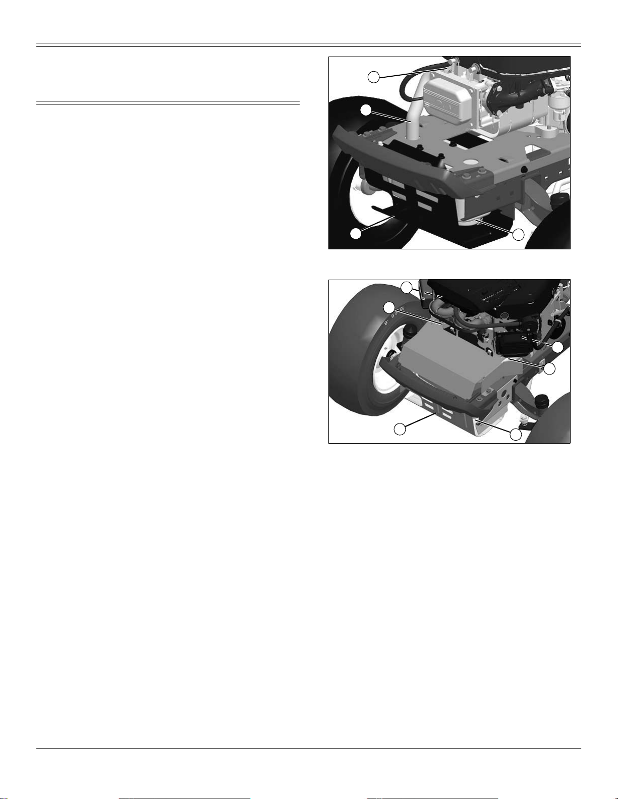
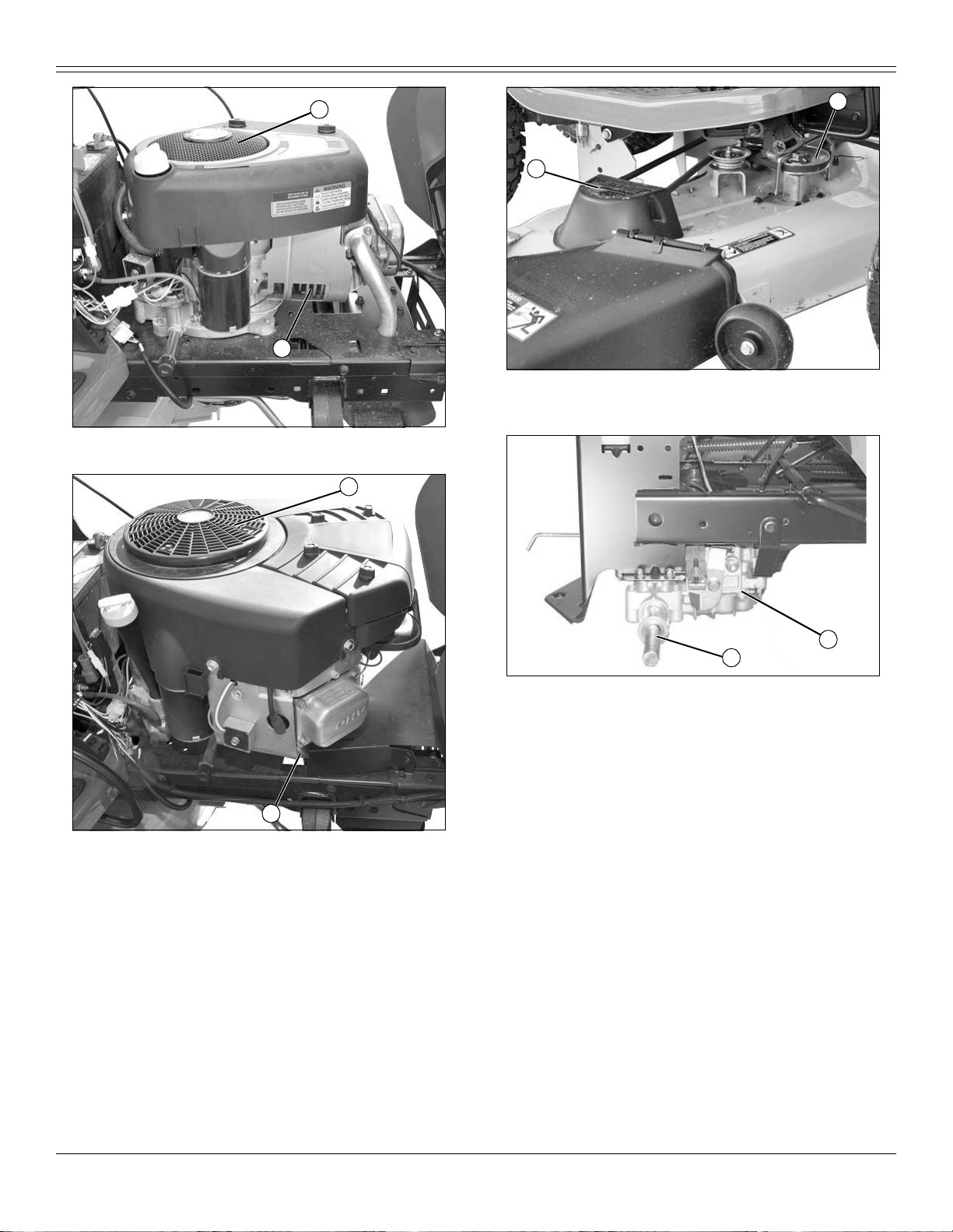
• Primary area s th at mu st be in s pe ct ed an d cl ea ne d on the mach in e
include (See Safety Label Section):
B
D
Picture Note: Single cylinder shown.
A
B
D
Picture Note: Twin cylinder shown.
a.Exhaust manifold (A), muffler pipe (B), muffler (C) and muffler shield
(D).
C
MX48341
A
B
C
MX48340
Machine Cleanout - 14
Page 16
MAC HINE CLEANOUT
Picture Note: Single cylinder shown.
E
G
F
c.Top of mower d eck, under shields (G), including spindle (H) and belt
areas.
MX49847
E
H
MX49849
F
MX49848
Picture Note: Twin cylinder shown.
b.Engine intake screens (E), cooling fins (F), and oil cooler (if equipped).
I
J
MX38694
Picture Note: Shown with wheel removed.
d.On or near transmission (I) and driveline (J).
Machine Cleanout - 15
Page 17
ASSEMBLY
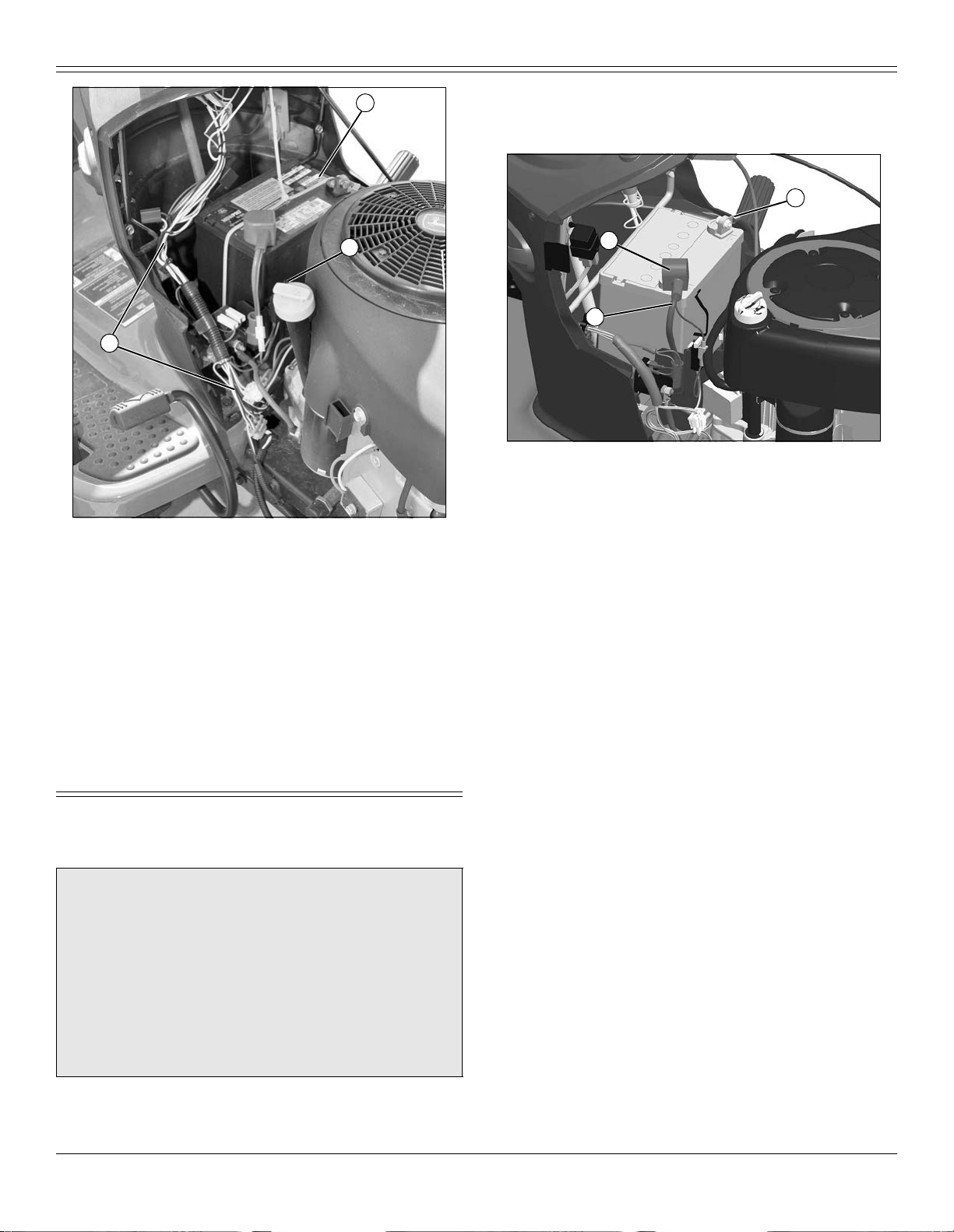
L
K
M
MX49850
e.Under left side panel near fuse block (K), and all wiring, including the
battery (L) and related wiring harnesses (M).
• Excess lubrication or fuel/oil leaks or spills on the machine can also
serve as collection sites for debris. Prompt machine repair and oil/fuel
cleanup will minimize the potential for debris collection and reduced
cooling throughout machine life.
• Bearing failures or overheating can result in a fire. To reduc e this risk,
always follow the instructions in the machine operator’s manual regarding
lubrication intervals and locations. Washing the machine while warm may
also reduce bearing life and increase potential for premature bearing
failure.
• Always shut off fuel when storing or transpo rting machine, if the machine
has a fuel sh utoff.
battery terminal.
3. Charge the battery.
• Battery is fully charged at 12.6 volts.
B
C
A
MX46480
4. Connect positive (+) battery cable (A) to battery.
5. Connect negative (–) battery cable (B).
6. Apply general purpose grease or silicone spray to t erminal to help
prevent corrosion.
7. Slide red cover (C) over positive battery cable.
Check Tire Pressure
Check tire pressure. (See Checking Tire Pressure in the SERVICE
MISCELLANEOUS section.)
Adjust Mower Deck Level
Adjust mower deck level. (See Adjusting Mower Level in the OPERATING
section.)
Check Engine Oil Level
Check engine oil level. (See Checking Engine Oil Level in the SERVICE
ENGINE secti on.)
Assembly
Charge and Connect Battery
c CAUTION: Avoid injury! The battery produces a flammable
and explosive gas. The battery may explode:
• Do not smoke or have open flame near battery.
• Wear eye protection and gloves.
• Never check battery charge by placing a metal object across
the posts. Use a voltmete r or hydrome ter.
• Do not jump start or charge a frozen battery. Warm battery to
16°C (60°F).
1. Remove and discard the tie strap from the positive (+) battery terminal.
2. Remove and discard the black protective cap from the negative (–)
Assembly - 16
Check Machine Safety System
Perform safety system check to make sure the electronic safety interlock
circuit is functioning properly. Perform all tests. (See Testing Safety
System in t he OPERATING section.)
Break In Electric Engagement Clutch (If Equipped)
1. Start engine and move ma chine to flat level surface.
Page 18
ASSEMBLY
A
B
MX49386
2. Push throttle lever (A) up to full thro tt le po sitio n.
3. Engage attachment engagement switch (B) and allow mower to run for
10 seconds.
4. Disengage attachment engagement switch and wait 10 seconds.
5. Repeat steps 3 and 4 for 12-15 cycles.
NOTE: Clutch is now properly burnished.
Assembly - 17
Page 19
Operating Controls
A
L
OPERATING CONTROLS
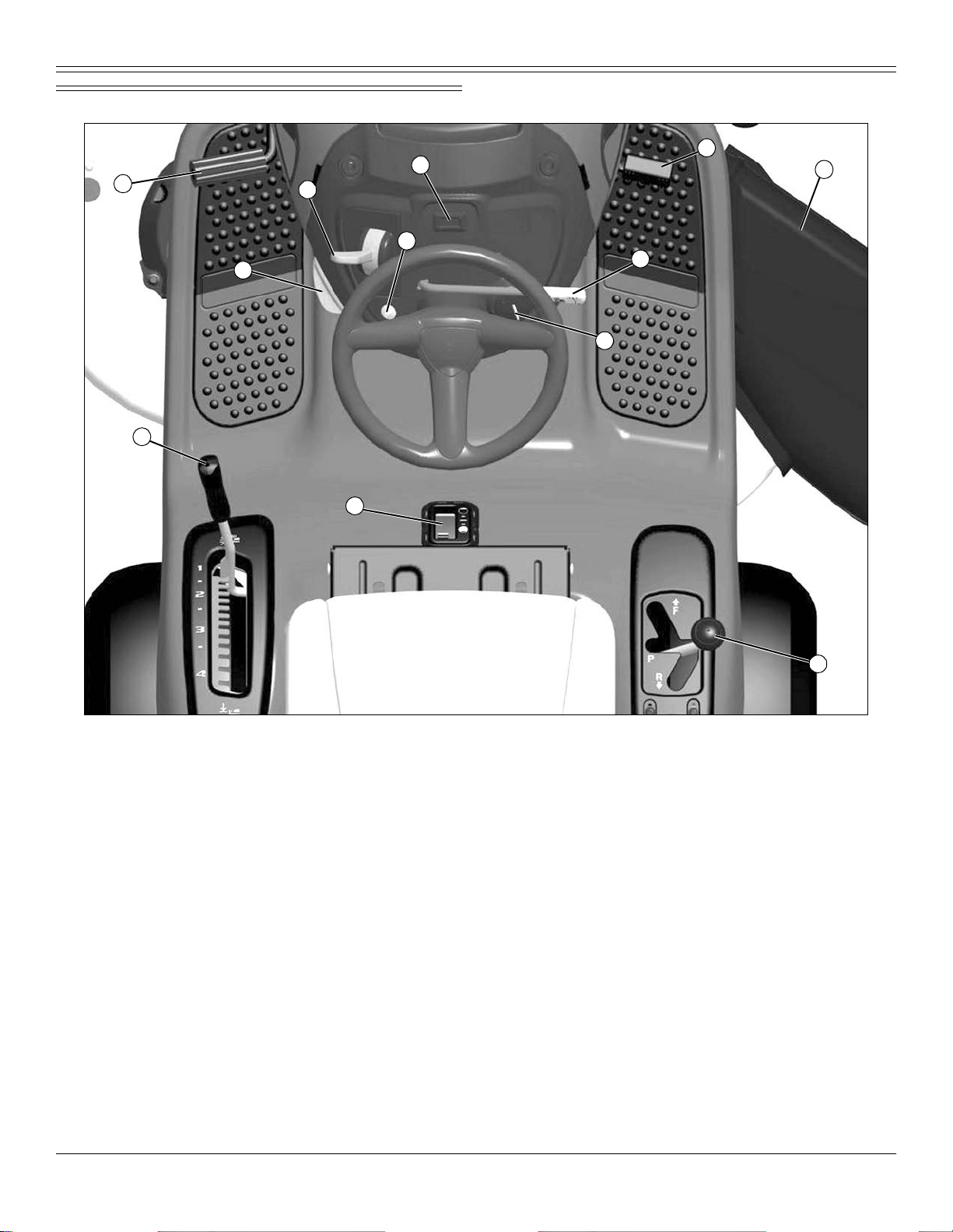
Operator Station Controls (D105)
H
E
C
D
B
G
F
I
ABrake Pedal
B Park Brake Lo ck Lever
C Throttle/Choke Lever
D Reverse Implement Option (RIO) Switch
E Service Reminder/Hourmeter
FKey Switch
G Attachment Engagement Lever
H Motio n Pedal
I Deflector Shield
J Transmissi on Shift Lever
K Fuel Level Window
L Attachment Lift Lever
K
J
MX51677
Operating Controls - 18
Page 20

OPERATING CONTROLS
Operator Station Controls (D110, D120, D130)
C
D
I
A
B
L
M
H
G
J
K
F
E
ABrake Pedal
B Park Brake Lock Lev er
C Throttle/Choke Lever
D Service Reminder/Hourmeter
EKey Switch
F Cruise Control Lever (D120 and D 130)
G Attachm e nt Eng ag em ent Lever
H Rev erse Implement Option (RIO) Switch
I Forward Travel Pedal
J Rev erse Travel Pedal
K Deflector Shield
L Fuel Level Window
M Att ac hm e nt Lift Lever
MX49390
Operating Controls - 19
Page 21

OPERATING CONTROLS
Operator Station Controls (D140, D160, D170)
D
A
B
C
G
E
L
H
F
I
J
K
M
ABrake Pedal
B Park Brake Lock Lever
C Throttle/Choke Lever
D Service Reminder/Hourmeter
EKey Switch
F Cruise Control Lever
G Reverse Implement Option (RIO) Switch
H Attach ment Engagement Switch
I Forward Travel Pedal
J Reverse Travel Pedal
K Deflector Shield
L Fuel Level Window
M Attachment Lift Lever
MX49389
Operating Controls - 20
Page 22

OPERATING
Operating
Daily Operating Checklist
❏ Test saf ety systems.
❏ Check tire pressure.
IMPORTANT: Avoid damage! Usin g stale, contaminated or
improper fuel can result in engine and fuel system damage.
Repairs caused by stale, contaminated or improper fuel are not
covered by warranty.
❏ Chec k fu el le vel. (See SER V IC E MISCE LLA NE OUS se ct ion, Us ing
Proper Fuel and Stabilizer)
4. Release seat adjustment lever to lock in position.
Lumbar Seat Adjustment (D160, D170)
• Turn lumbar seat adjustment dials (B) on either side of seat to adjust
firmness of seat.
Adjusting Cutting Height
Cutting height can be adjusted from approximately 25 - 100 mm (1 - 4 in.)
in 6.4 mm (1/4 in.) increments. When mower deck is in transport position,
cuttin g he ight is app roxim a tely 100 mm (4 in.) .
Detents allow the adjustment lever to be positioned at each indicated
mower s etting, as wel l as the mid-point between each s etting.
Mower Setting Approximate Cutti ng H eig ht
1 25 mm (1 in.)
❏ Check engine oil level.
❏ Remove grass and debris from engine compartment and muffler
area, and on top of mower deck, before and after operating machine.
❏ Clea n air intake screen.
❏ Check area below machine for leaks.
Avoid Damage to Plastic and Painted Surfaces
• Do not wipe pl astic parts unless rinsed first. Using a dry cloth may cause
scratches.
• Insect repellent spray may damage plastic and painted surfaces. Do not
spray insect repel lent near machine.
• Be careful not to spill fuel on machine. Fuel may damage surface. Wipe
up spille d fu el im m ed ia t el y.
• Prolonged exposu re to sunlight w ill damage hood s urfaces.
Adjusting Seat
1. Sit in seat.
B
A
– 38 mm (1 1/2 in.)
2 50 mm (2 in.)
– 65 mm (2 1/2 in.)
3 75 mm (3 in.)
– 90 mm (3 1/2 in.)
4 (Transport) 100 mm (4 in.)
1. Put attachment lift lever into the slot adjacent to desired cutting height.
2. Adjust mower deck wheels.
Transporting or Getting On and Off Machine
• Pull attachment lift lever all the way back to transport position or 100 mm
(4 in.) cutting height.
Checking and Adjusting Mower Deck Level
c CAUTION: Avoid injury! Rotating blades are dangerous.
Before adjusting or servicing mower:
• Disconnect spark plug wire(s) or battery negative (-) cable to
prevent engine from starting accidently.
• Always wear gloves when handling mower blades or working
near bl ades.
NOTE: Mower deck wheels should not contact the ground when
leveling the mower deck.
Method One
1. Make sure machine is on a flat, level surface.
2. Park machine safely. (See Parking Safely in the SAFETY section.)
3. Check that tires are inflated to correct tire pressure. Tire pressure is
marked on the side of the tire.
MX46483
2. Lift up on seat adjustment lever (A) on right side of seat.
3. Lean forward and slide seat forward or rearward to desired position. Do
not lean back on top of seat to push rearward.
Operating - 21
Page 23

OPERATING
A
A
A
M17687a
Picture Note: 107 cm (42 in.) mower deck shown
4. Place three short 51 mm (2 in.) blocks of wood under the edges (A) of
the mower deck.
5. Lower mower deck to the 65 mm (2.5 in.) cutting height position.
6. Check that the mower deck is level and lightly touching each of the
three wooden blocks.
C
MX51678
Picture Note: 107 cm (42 in.) mower deck shown
• If the front of the mower deck is not lightly touching the front block,
adjust the front draft arm by turning the nut (C).
7. Raise the cutting height to the next highe st position and remove the
three wooden blocks.
8. Turn the nut (C) on the front draft arm counterclockwise 1-2 full turns so
that the front of the deck is 3-6 mm (1/8-1/4 in.) lower than the rear. This
adjustment prevents “double cutting,” which wastes horsepower and
causes brown gras s tip s.
B
C
MX16561
• If the rear of the mower deck is not touching the rear blocks, or is
sitting heavily on the blocks, adjust the rear lift links by turning the
leveling nut (B) on each lift link. The blocks should be able to easily slide
in and out beneath the mo wer deck when the mower deck is correctly
adjusted.
Method Two
NOTE: An optional mower deck leveling gauge (AM130907) is
available from your John Deere dealer. It allows for precision mower
deck leveling by measuring mower deck level at the blade tips.
1. Make sure machine is on a flat, level surface.
2. Park machine safely. (See Parking Safely in the SAFETY section.)
3. Inflate tires to the correct pressure.
4. Move mower lift handle to preferred cutting height.
5. Measu re mower deck level (side-to-side).
B
A
MX4871
Picture Note: A convenient leveling gauge (A) (AM130907) is
available from your dealer.
a.Position mower blades as follows and me asure from each outside
blade tip (B) to the level surface.
Operating - 22
Page 24

OPERATING
C
b.Turn left b l ad e (C) a s s ho w n. H o ld drive belt and turn ri ght b la de (D ) as
shown. Take measurement for both blades.
The difference between blade measurements must not be more than 3
mm (1/8 in.).
E
c.Adjust mower deck le vel, if necessary, by turning rear nuts (E)
clockwise to raise the side of the mow er deck, or counterclockwise to
lower the mower deck.
6. Measure mower level (front-to-rear).
D
MX4896
MX16561
G
MX51678
Picture Note: 107 cm (42 in.) mower deck shown
c.Adjust mower deck level, if necessary, by turning the nut (G)
counterc lockw i se to lower the fro nt of deck or cl ockwis e to rais e front of
deck.
Adjusting Mower Deck Wheels
IMPORTANT: Avoid damage! The mower deck can be damaged if
mower wheels are adjusted wrong:
• Wheels must not ride on ground supporting mower weight.
• Check wheel adjustment each time cutting height is changed.
1. Park machine safely. (See Parking Safely in the SAFETY section.)
2. Inflate tires to the correct pressure.
3. Lower mower dec k to the desired mowing position.
NOTE: Bottom of wheels should be approximately 3-13 mm (1/8-1/2
in.) from the ground.
A
B
F
MX4896a
a.Turn right blade (F) so blade tip points straight forward.
b.Measure from blade t ip to the surface. Take measurement for both
blades.
The front blade tip must be 3–6 mm (1/8 -1/4 in.) lower than rear blade
tip.
Operating - 23
MX10509a
4. Check each mower wheel position. Remove nut (A) and bolt (B), and
move mower wheel to proper hole.
Page 25

A
B
C
D
A- 38 mm (1.5-In.)
B- 51 mm (2-In.)
C- 64 mm (2.5-In.)
D- 76 mm (3-In.) and above
OPERATING
3. Unlock the park brake.
4. Try to start engine.
Result: Engine must not start. If engine starts, there is a problem with
your safety interlock circuit.
Testing Park Brake
1. Park machine safely. (See Parking Safely in the SAFETY Section.)
2. Lock the park brake.
3. Put transmission in park. Engage bypass ro d located at rear of
machine.
4. Try to push machine manually.
MIF
Result: Park brake must prevent machine from moving. If machine moves,
parking brake needs to be adjusted.
Testing Attachment Engagement Switch or Lever
5. Install bolts and nuts to lock wheels in position. Tighten nuts to 34 N•m
(25 lb-ft).
Testin g Safety Systems
c CAUTION: Avoid injury! Engine exhaust fumes contain
carbon monoxide and can cause serious illness or death.
Do not run an engine in an enclosed area, such as a garage, even
with doors or windows open ed.
Move the machine to an outsid e area before r unn ing the engi ne .
The safety systems installed on your machine should be checked before
each machine use. Be su re you have read the machine operator manu al
and are completely familiar with the operation of the machine before
performing these safety system checks.
Use the following checkout procedures to check for normal operation of
machine.
If there is a malfunction during one of these procedures, do not operate
machine. See your authorized dealer for service.
Perform these tests in a clear open area. Keep bystanders a way.
Testin g Park Brake Switch
1. Park machine safely . (See Parking Safely in the SAFETY Section.)
2. Sit on seat.
c CAUTION: Avoid injury! The mower blades should stop in
approximately five seconds when the mower or PTO is
disengaged.
If you believe that your blades may not be stopping in that period
of time, take your machine to your authorized dealer where they
can safely check and service your machine.
1. Park machine safely. (See Parking Safely in the SAFETY Section.)
2. Sit on seat.
3. Lock the park brake.
4. Engage mower:
• On models with electric attachment engagement switch, pull switch
up.
• On models wi th mechanical attachment en gagement le ver, pu sh lever
forward.
5. Try to start engine.
Result: Engine must not start. If engine starts, there is a problem with
your safety interlock circuit.
Te sting Seat Switch
1. Park machine safely. (See Parking Safely in the SAFETY Section.)
2. First test:
a.Start engi ne.
b.Move throttle lever up to maximum engine speed.
c.Unlock park brake.
d.Engage mower .
e.Raise up off seat. Do not get off machine.
Result: Engine and mower blades should stop. If engine and mower
blades do not stop, there is a problem with your safety interlock circuit.
3. Second test:
a.Lock pa r k brake.
b.Disengage mower.
c. St a rt engi ne.
d.Unlock park brake.
Operating - 24
Page 26

OPERATING
e.Rais e up off seat. D o no t get off machine.
Result: Engine should stop . If engine does not stop, there is a problem
with your safety interlock circuit.
4. Third test:
a.Di se ng ag e mow e r.
b.Start en gine.
c.Lock park brake.
d.Rais e up off seat. D o no t get off machine.
Result: Engine should continue to run. If engine stops, there is a problem
with your safety interlock circuit.
Testi ng Reverse Implement Option (RIO)
1. Park machine safely. (See Parking Safely in the SAFETY section.)
2. Start engine.
3. Engage attachment engagement switch or lever to start attachment.
c CAUTION: Avoid injury! Rotating blades are dangerous.
Children or bystanders may be injured by runover and rotating
blades.
Before backing up, carefully check the area around the machine.
4. Look behind the vehicle to be sure there are no bystanders.
5. Begin reverse travel by depressing reverse pedal for hydrostatic
transmissio n or mov in g auto ma tic sh ift lever to R (reverse) posi tio n for
automatic transmission and depressing pedal.
Result: Attachment and engine should stop operation. If attachment or
engine continues to operate as machine begins travel in reverse, do not
continu e to operate ma c hine.
Using the Park Brake
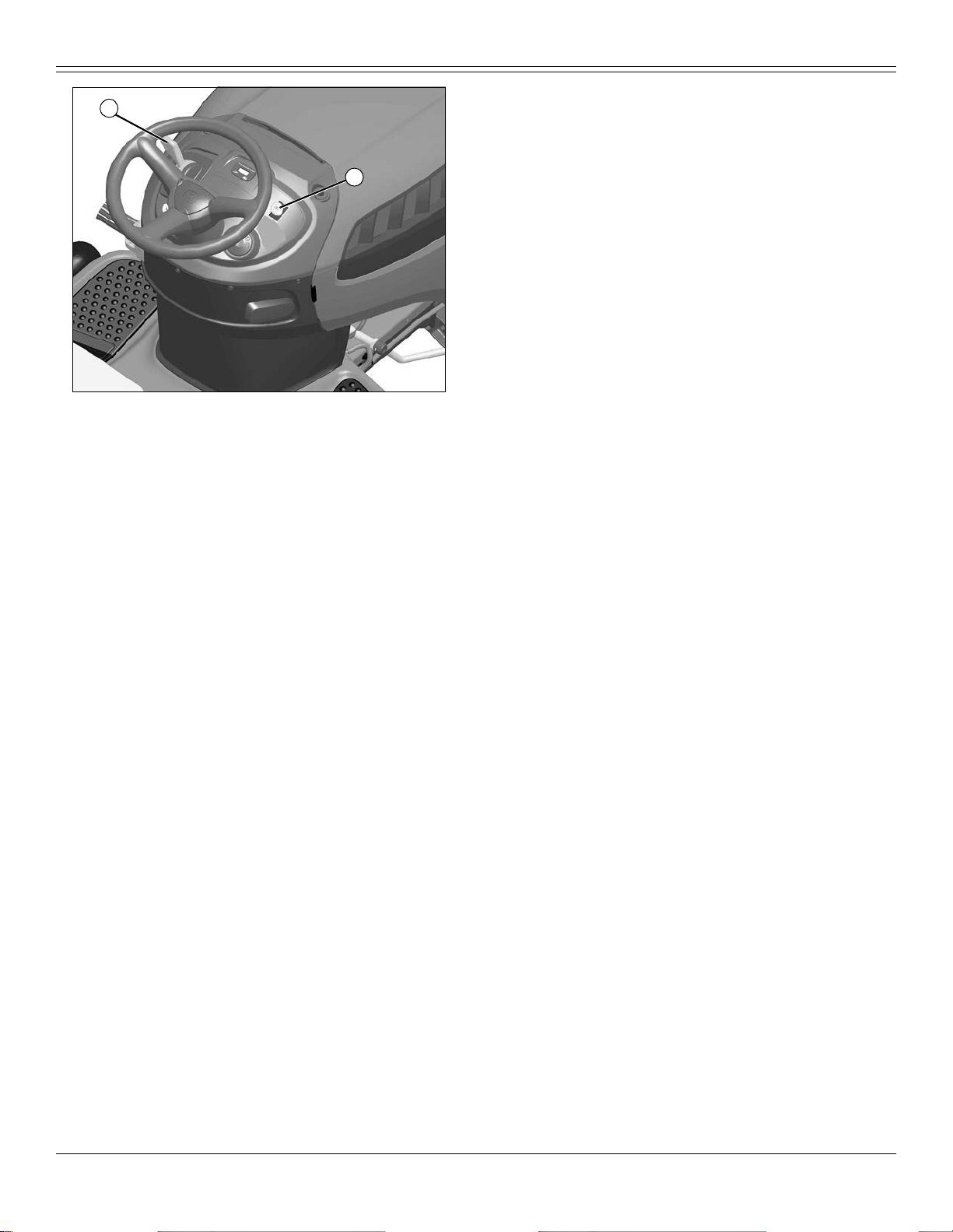
Using the Hourmeter and Service Reminder
A
D
B
• The hou rmeter (A) shows the number of hours the engine has run. The
service reminder will indicate that a g eneral lubrication (B) or mow er/
engine (C) service interval has been reached. When service is required,
the service “SVC” arrows (D) will periodically flash for two hours. Follow
the service timetable on the maintenance schedule located under the
seat. For specific service procedures, see the Servi ce section of this
manual.
• Hourmeter cannot be reset.
• The hourmeter display will always be on.
• The decimal point will flash while the hourmeter is accumulating time.
D
C
MX49388
Using Key Switch and Headlights
B
C
c CAUTION: Avoid injury! Children or bystanders may
attempt to move or operate an unattended machine.
Always lock the park brake and remove the key before leaving the
machine unattended.
Locking park brake:
1. Push and hold brake pedal down.
2. Pull park brake lever up to lock park brake.
3. Release brake pedal. Pedal should stay down and park brake lever
should stay locked.
Unlocking pa rk brake:
1. Push and hold brake pedal down.
2. Push park brake lever down to unlock park brake.
3. Release brake p edal.
Operating - 25
A
D
M94336a
A- STOP Position
B- Headlights On Position
C- Run Position
D- Start Position
Engine Off
NOTE: Headlights will drain the battery rapidly if key switch is left in
headlights on position (B) with the engine off.
• To turn headlights on, turn key switch to headlights on position (B).
• To turn headlights off, turn key switch to STOP position (A).
Engine On
• T o turn headlights on, start engine, then turn key switch from run position
(C) to headlights on position (B).
Page 27

OPERATING
• To turn headlights off, turn key switch from headlights on position (B) to
run position (C).
Starting the Engine
IMPORTANT: Avoid damage! Hydrostatic transmission might be
damaged if the bypass rod is not pushed back to operating
position before attempting to start the engine. Do not start or
operate the machine with the bypass rod in the pulled-out
position.
1. Make sure bypass rod is pushed in.
c CAUTION: Avoid injury! Engine exhaust fumes contain
carbon monoxide and can cause serious illness or death.
Do not run an engine in an enclosed area, such as a garage, even
with doors or windows open ed.
Move the machine to an outsid e area before r unn ing the engi ne .
2. Sit in seat.
3. Make sure mower is disengaged. (See Engaging and Disengaging
Mower in the OPERATING s ection.)
4. Lock the park brake.
5. For automatic models, put transmission in park.
6. Check starting conditions:
A
• Repeat procedure if necessary.
IMPORTANT: Avoid damage! Unnecessary engine idling may
cause engine damage. Excessive idling can cause engine
overheating, carbon build-up, and poor performance.
9. Let engine run at high idle for a couple of minutes to warm-up before
operating machine.
Idling the Engine
IMPORTANT: Avoid damage!
Unnecessary engine idl ing may cause engine or transmission
damage. Excessive idling can cause engine overheating, carbon
build-up, and poor performance.
Idling or low throttle operation while mowing, climbing hills, or
towing could result in transmission overheating. always operate
at full throttle on ce the engine is warm.
Do not operate machine with hood open. Hood must be closed for
proper engine cooling and exhaust.
• Engine is air cooled and needs a large volume of air to keep cool. K eep
air intake screen on top of engine clean.
• Keep hood closed when engine is idling.
Stopping the Engine
IMPORTANT: Avoid damage! Do not stop the engine by moving
choke control to the choke position. Backfire, fire or engine
damage can occur. Follow recommended procedure for stopping
engine.
MX49386
• If engine is co ld: Mo v e thr ot tl e/ ch ok e le v e r (A ) up to the cho k e po si tion .
• If engine is warm: Move throttle/choke lever (A) to the half-speed
position.
IMPO R TANT : A v o i d da ma ge ! Sta rter ma y be da m a ge d if sta rt e r is
operated for more th an 20 seconds at a time:
• Wait two minutes before trying again if engine does not start.
7. Turn key to start position for no more than five seconds.
8. Release key to run position when engine starts, and gradually move
choke lever down to the off position.
• If engine does not start, wait 10 seconds.
• Turn key to start position again for no longer than 5 seconds.
1. Let engine run at high throttle without load for a few seconds.
2. Turn key to STOP position. Engine will stop and headlights will turn off.
3. Remove key.
4. Lock the park brake.
Using Travel Controls on Automatic Transmission
c CAUTION: Avoid injury! Children or bystanders may be
injured by runover and rotating blades. Before traveling forward or
rearward:
• Careful ly check the area around the machine.
• Disengage the mower before backing up.
IMPORTANT: Avoid damage! Stop machine movement before
shifting between reverse and forward to prevent transmission
damage.
Operating - 26
Page 28

OPERATING
T ravel Forward
B
1. Completely remove foot from travel pedal (A).
2. Push brake pedal (B) all the way down to stop machine.
3. Move transmission shift lever to forward (C).
4. Release brake p edal.
5. Slowly apply foot to travel pedal.
T ravel in Reverse
1. Completely remove foot from travel pedal (A).
NOTE: Any operating attachment and the engine will stop as the
transm is si o n shift lever is moved to R (reve rse) wi th attachmen t
engaged.
2. It may be required to push brake pedal to stop machine when on a
slope.
3. Move transmission shift lever to reverse (D).
4. Look behind the machi ne to be sure there are no bystan ders nearby.
5. Release brake p edal.
6. Slowly apply foot to trvael pedal.
Emergency Stopping
Push brake pedal all the way down to stop machine.
A
C
D
MX51677
Using Travel Controls on Hydrostatic Tran sm ission
c CAUTION: Avoid injury! Children or bystanders may be
injured by runover and rotating blades. Before traveling forward or
rearward:
• Carefully check the area around the machine.
• Disengage the mower before backing up.
Travel Forward
C
B
• Push down the forward travel pedal (A).
Travel in Reverse
NOTE: Any operating attachment and the engine will stop as the
reverse motion pedal is pressed with attachment engaged.
1. Disengage attachment:
• On models with mechanical attachment engagement lever (B), pull
lever back to the off position.
• On models with electric attachment engagement switch, push switch
in loca tion (C) (not sh own above) down to the off position.
2. Look behind the machine to be sure there are no bystanders nearby.
3. Touch the r everse travel pedal (D) with front of foot and slide foot over
pedal f rom front to rear.
Emergency Stopping
• Push brake pedal all the way down to stop machine.
A
D
MX46484
Using The Reverse Implement Option (RIO)
c CAUTION: Avoid injury! Children or bystanders may be
injured by runover and rotating blades. Before traveling forward or
rearward:
• Careful ly check the area around the machine.
• Disengage the mower before backing up.
NOTE: Backing up while the mower is engaged is strongly
discouraged. The Reverse Implement Option should be used only
when operating another attachment or when the operator deems it
necess ary to repositi on the machine with the mowe r engaged.
1. Stop forward travel.
2. Look behind the machine to be sure there are no bystanders.
Operating - 27
Page 29

OPERATING
• On models with electric attachment engagement switch: Pull switch
up.
• On models with mechanical attachment engagement lever: Push lever
forward.
NOTE: The mower and engine will stop as the reverse foot pedal is
pressed for hydrostatic transmission or when the automatic shift
lever is moved to the R (reverse) position for automatic transmission
with mower engaged.
5. Disengage mower blades before moving in revers e or stopping engine.
• Machines with mechanical attachment engagement lever: Pull lever
A
back.
• Machines with electric attachment engagement switch : Push switch
down.
MX46484
3. Push and hold in the reverse implement switch (A) while depressing
reverse pedal slightly for hydrostatic transmission or moving the automatic
shift lever to the R (reverse) position for automatic transmission.
NOTE: If the engine and mower stop while repositioning the
machine, return the attachment engagement lever/switch to the off
position. Start engine and engage mower. Begin again with Step 2.
4. Release the reverse impleme nt switch and reposition the machine as
the machine begins to move rearward.
5. Resume forward travel. The mower should continue operating.
6. Repeat procedure to position the machine again.
Using Cruise Control (D120, D130, D140, D160, D170)
c CAUTION: Avoid injury! Do not use cruise control when
going down hills. Machine speed will increase. Operate machine in
a large, open ar e a t o lea rn how t he cr u ise co ntr ol wor k s.
Use cruise control when you want to maintain travel speed without having
to hold the forward travel pedal down. Cruise control operates only for
forward travel.
Engage Cruise Control
1. Push forward pedal down until you reach desired travel speed.
2. Pull cruise control lever up and release forward pedal to lock the cruise
control.
Disengage Cruise Control
• Depress brake pedal, tap on forward pedal or push cruise control lever
down to the off position.
Engaging and Disengaging Mower
NOTE: Put attachment lift lever in transport position to transport
machine or when parking machine.
1. Start engine and run at half speed for a couple of minutes to warm up.
2. Lower mower deck to desired cutting height position.
NOTE: Throttle lever should be at full throttle position before
engaging mower to avoid stalling engine.
3. Push throttle lever up to the full throttle position.
4. Engage mower.
Using Wash Por t to Clea n Mower Deck
NOTE: Follow this procedure after each use to prevent buildup and
remove corrosive lawn chemic als.
1. Park machine safely. (See Parking Safely in the Safety section).
A
MX38397
2. Attach quick-coupler to garden hose.
3. Attach garden hose with quick-coupler to wash port (A) on the mower
deck.
4. Turn on water.
5. Start engine.
6. Run at full throttle.
7. Engage mower blades.
8. Flush water under deck for approximately one mi nute.
9. Disengage mower blades.
10. Stop engine.
11. Turn off water and remove garden hose and quick-coupler from wash
port.
12. Remove quick-coupler from garden hose and store for future use.
Operating - 28
Page 30

OPERATING
Unplugging Mower, Bagger, or Material Collection System
c CAUTION: Avoid injury! Do not attempt to unplug
attachment with machine running.
• Rotating blades are dangerous. Shut off the engine and
remove the key before getting off the seat to inspect the
machine and attachment.
• Thrown objects can cause serious injury. Make sure all
machine parts are stopped before raising hopper top or
removing chutes.
Checking For Plugging While Driving
If grass builds up in front of mower discharge chute, check for plugged
chute or problems with blower assembly (if equipped).
If there is a trail of clippings behind mower or clippings blow to the side,
check for plugged chute, full collector bags, or problems with blower
assembly.
Removing Debris From Inspection Points:
c CAUTION: Avoid injury! Do not use hands or feet to clear
plugged mower deck or blower assembly. Stored energy can cause
blades to rotate.
1. Park machine safely. Wait for all moving parts to stop before getting off
to inspect machine.
2. Open ho pp er cove r. Che ck ch ute ou t le t .
3. Remove chut e fr om mow er deck or blower as se m bl y. Check chut e inl et.
4. Check under mower deck for debris.
Moving Machine by Hand
c CAUTION: Avoid injury! When the bypass valve is open, the
machine will have unrestricted motion.
• Do not open the bypass valve when the machine is stopped
on an incline to prevent it from going downhill out of control.
IMPORTANT: Avoid damage! Transmission damage m ay occur i f
the machine is towed or moved incorrectly:
• Move machine by hand only.
• Do not use another vehi cle to move machine.
• Do not tow machine.
1. Unlock the park brake.
2. Put automatic transmission in P (park).
A
MX16558
3. On automatic and hyd rostatic Models: Pull out on by pass rod (A).
4. Push machine to desired location.
IMPORTANT: Avoid damage! Hydrostatic transmission might be
damaged if the bypass rod is not pushed back to operating
position before attempting to start the engine. Do not start or
operate the machine with the bypass rod in the pul led-out
position.
5. Push bypass rod back in.
6. Lock the park brake.
Transporting Machine on Trailer
NOTE: Trailer capacity must exceed combined machine weight and
attachmen t weight. (See Spe cif ica tions section in ope rato r ’s
manual.)
Be sure the trailer has all necessary lights and signs required by law.
c CAUTION: Avoid injury! Use extra care when loading or
unloading the machine onto a trailer or truck.
• Park trailer on a level surfa ce .
• Use of a trailer with sides is recommended.
• Keep wheels away from drop-offs and edges.
• Back slowly and in a straight line.
• Close fuel shut-off valve, if your machine is equipped.
• Do not secure machine using optional bumper as this can
dislodge during transport.
IMPORTANT: Avoid damage! Transporting a machine on a trailer
or on a truck bed at high speeds can result in hood or engine
cover raising and possibly coming off machine if not secured.
• Position machine on trailer so hood or engine cover opens from
rear of trailer to prevent wind from blowing hood or cover open.
• Secure hood or engine cover with existing machine locks or
latches.
• Secure hood or engine cover with tie down straps if no locks or
latches exist.
1. Park trailer on a level surface.
2. Raise mower deck, if installed, before drivi ng machine onto trailer.
Operating - 29
Page 31

OPERATING
3. Drive machine onto heavy-duty trailer. Position machine on trailer so
hood or engine cover will not raise in wind while being transported.
4. Lower mower deck completely.
5. Lock park brake.
6. Turn off machine and remove key.
A
MX49387
7. Secure front of machine at both sides of the axle at points (A) to trailer
with heavy-duty straps, chains, or cables. Straps must be directed down
and outwar d fro m machine.
C
MX51679
Picture Note: D105 shown.
9. For automatic transmission machines, secure rear of machine at both
sides of the axle at points (C) to trailer with heavy-duty straps, chains, or
cables. Straps must be directed down and outward from machine.
10. Secure ho od to prevent from lif tin g whi le dr iv in g.
IMPORTANT: Avoid damage! Do not secure machine using
transmission housing.
B
MX43712
8. For hydrostatic transmissions, secure rear of machine at both sides of
the axle at points (B) to trailer with heavy-duty straps, chains, or cables.
Strap s must be directed down and outward from machine.
Using Weigh t s
c CAUTION: Avoid injury! The machine may become unstable
when ope r ating on sl ope s and/or wit h some attach ments.
Use weights to improve stability when operating on slopes or
using attachments.
Remove weights when not required.
IMPORTANT: Avoid damage! Never use liquid in tires or wheel
weights as ballast. Transmission damage can occur.
When rea r ballast is needed, use only the approved rear weight
bracket and attaching weights.
NOTE: See your authorized dealer for recommended weights.
• Install fr ont wei gh t s f or adde d st ab il ity and st eeri ng con tro l wh en yo u us e
equipment such as the rear-mounted grass bagger.
• Install rear weights when using the snow blade or snowblower.
• Remove weights when not required.
Using Ti re C hai ns
IMPO RTANT: Avoid damage! Do not use chains with mower deck
or tiller.
Tire chains are recommended for use with most front attachments.
Remove tire chains before installing mower deck.
See your attachment Operator’ s Manual for tire chain recommendation.
See yo ur authorized dealer for the chains.
Operating - 30
Page 32

SERVICE INTERVALS
Using Accessories
B
Using the Power Port (If Equipped)
• Adjust cutting height to remove only 1/3 of the grass at a time.
• Do not mow wet grass.
• Mow grass often. Short grass clippings w ill decay quickly.
• Mow with engine at full throttle.
• Adjust travel spee d to match mowing conditions:
• Travel at slow speed when you mow thick, tall grass, make sharp turns
or trim around objects.
• Travel at moderat e sp eed when you mow thi n gr as s.
• Use a different mowing pattern each time you mow. Overlap mowing
paths 50 - 100 mm (2 - 4 in.).
A
B
MX46479
• Drive over ridges and through shallow ditches straight-on, not at an
angle.
c CAUTION: Avoid injury! Safe operation requires your full
attention. Do not wear radio or music headphones while operating
machine.
An electric power port (A) can be used for accessories. See your
author ized deal er.
Using CargO Mount System™
The front and rear CargO Mount System™ brackets (B) can be used for
easy attachment of selected optional equipment.
Use John Deere approved optional equipment only. See your Authorized
Service Center for approved optional equipment.
Choosing Mower Blades
Three types of mower blades are available for use with D series mowers.
• 3-N- 1 blades. These are general purpose blades that are best suited for
side-di s charge op er at io n, but ca n be use d wi th a ba gg er attachm e nt, or
with a mulch cover installed. They are not designed for optimal
perfor ma nc e whe n ba gg ing or mulch in g.
• Bagg er blades. These blades ar e designed fo r optimal performance
when used wi th ba gg er attachme nts .
• Mulching blades. These blades are designed for optimal performance
when used with a mulch cover installed.
Mowing Tips
The following recommendations will produce the best lawn cut quality and
appearance:
• Keep mower blades sharp. Dull blades will tear grass; tips of grass will
then turn brown.
• Cutting grass too sh ort may kill grass and let weeds grow easily. The
suggested finished cut height range is 44 - 70 mm (1.75 - 2.75 in.).
MIF
• Mow around the outside twice, then mow inside in straight passes. Best
cut is achieved when mowing in a straight line.
• When mowing or mulch ing near pavement, overlap the pavement by 50
mm (2 in.) to allow clippings to dispense over grass.
• A thick layer of mul che d l ea v es c an pr ev e nt su nlig ht f rom g et tin g t o gr a ss
and smother it. Taller grass heights allo w mulched leaves to dispense
easier in lawn. Mulch leaves several times if needed.
• Use a thatc he r in la te spr ing or sum mer t o pul l up de ad gr a ss an d aer at e
ground.
• For Mulching Mower: Shorter cut heights w ill provide better cut quality,
but may leave noticeable clippings. Higher cut heights will reduce
clippings, but cut quality may decline.
Service Intervals
Servicing Your Machine
IMPORTANT: Avoid damage! Operating in extreme conditions
may require more frequent service intervals:
• Engine components may become dirty or plugged when
operating in extreme heat, dust or other severe conditions.
• Engine oil can degrade if machine is operated constantly at slow
or low engine speeds or for frequent short periods of time.
Please use the following timetables to perform routine maintenance on
your mac hine.
Park the vehicle safely. See Park Safely in the SAFETY Section.
Service Intervals - 31
Page 33

SERVICE LUBRICATION
Service Intervals
After First 8 Hours
• Change en gi ne oil.
• On 107 cm (42 in.) deck: Check and adjust mower dec k belt tension.
• On 107 cm (42 in.) deck: Check and adjust mower deck spindle brakes.
• Lubricate mower spindles
• Lubricate mower pivot points.
• Lubricate front axle pivot.
• Lubricate front axle wheel spindles and bushings.
Every 25 Hours
• Lubricate mower spindles.
• Lubricate mower pivot points.
• Lubricate front axle pivot.
• Lubricate front axle wheel spindles and bushings.
Every 50 Hours
• Change engine oil and replace filter. (Service more frequently under
dusty co ndition s.)
• Clean/replace air filter precleaner. (Service more frequently under dusty
conditions.)
• Replace air filter element. (Service more frequently under dusty
conditions.)
• Clean/replace emis sion filter (if equipped).
• Clean engine cooling fins.
• Replace fuel filt er.
• Replace spark plug(s).
• Clean battery terminals.
• Shar pen/replace mower blades.
• Check/replace mower drive belt.
• Clean mower deck.
• Check/ leve l mow e r deck .
• On 107 cm (42 in.) deck: Check/adjust mower deck belt tension.
• On 107 cm (42 in.) deck: Check/adjust mower deck spindle brakes.
Every 200 Hours
• Check/adjust valve clearance. See your John Deere dealer for this
service.
The fol lowing greases are preferred:
• John Deere Multi-Purpose SD Polyurea Grease
• John Deer e Multi-Purpose HD Lithiu m Complex Grease
If not using any of the preferred greases, be sure to use a general all-
purpose grease with an NLGI grade No.2 rating.
Wet or high speed conditions may require use of a special-use grease.
Contact your Servicing dealer for information.
Lubricating Front Axle
C
A
B
MX16565
Wheel Sp indles and Bushings
NOTE: The D170 model does not require lubrication at the hub
grease fitting (B).
• Lubricate front wheel spindle grease fitting (A) and wheel hub grease
fitting (B), one on each side, with one or two shots of general all-purpose
grease.
Front Axle Pivot
• Lubricate front axle center pivot grease fitting (C) with one or two shots of
general all-purpose grease.
Lubricating Pivot Points
107 cm (42 in.) Mower Deck:
A
B
Service Lubrication
Grease
IMPORTANT: Avoid damage! Use recommended John Deere
greases to avoid component failure and premat ure wear.
The recommended John D eere greases are effective within an
average air temperature range of - 29 to 135 degree s C (-20 to 275
degrees F).
If operating outside that temperature range, contact your
Servicing dealer for a special-use grease.
Service Lubr ication - 32
C
C
MX25899
A- Blade Brake Pivots
B- Deck Idler Pivot
C- Spindle Grease Fitting (2)
• Lubricate the blade brake pivots (A) and deck idler pivot (B) w ith a
general all-purpose spray lubricant.
Page 34

SERVICE ENGINE
• Lubricate the two spindle grease fittings (C) with one or two shots of
general all-purpose grease.
122 cm (48 in.) and 137 cm (54 in.) Mower Decks:
SAE 15W-40
SAE 10W-40
SAE 10W-30
SAE 5W-30
A
B
MX25900
Picture Note: 122 cm (48 in.) mower deck used for illustration.
A- Deck Idler Pivot
B- Spindle Gre ase Fitting (3)
• Lubric ate the deck idler pivot ( A) with a general all-purpose spray
lubricant.
• Lubricate the three spindle grease fittings (B) with one or two shots of
general all-purpose grease.
Service Engine
Engine Warranty Maintenance Statement
Mainte na nc e, r ep ai r, or replac ement of the em is s io n con t ro l devi ce s an d
systems on this engine, which are being done at the customer’s expense,
may b e performed by any non-road en gine repair establishment or
indiv idual. Warr anty repairs must be perfo rmed by an authorized John
Deere de al er.
Avoid Fumes
c CAUTION: Avoid injury! Engine exhaust fumes contain
carbon monoxide and can cause serious illness or death.
Do not run an engine in an enclosed area, such as a garage, even
with doors or windows open ed.
Move the machine to an outsid e area before r unn ing the engi ne .
10050122
40
10
60 80
20 30
-20 0 20 40
-40
-40
The fol lowing John Deere oils are preferred:
• TURF-GARD™
• PLUS- 4™
• PLUS-50™ II
Other oils may be used if above John Deere oils are not available,
provided they meet the following specification:
• API Service Classification SJ or higher
-20-30
32
F
C
0
-10
Checking Engine Oil Level
IMPORTANT: Avoid damage! Failure to check the oil level
regularly could lead to serious engine problems if oil level is out
of the operating range:
• Check oil level before operating.
• Check oil level when the engine is cold and not running.
• Keep oil level between the dipstick marks.
• Shut off engine before adding oil.
NOTE: Check oil twice a day if you run engine over 4 hours in a day.
Make sure engine is cold when checking engine oil level.
1. Park machine safely. (See Parking Safely in the SAFETY section.)
2. Lift hood.
3. Clean area around dipstick to prevent debris from falling into crankcase.
Engine Oil
Use oil viscosity based on the expected air temperature range during the
period between oil changes.
Service Engine - 33
Page 35

SERVICE ENGINE
A
MX49394
Picture Note: Twin cylinder engine shown.
4. Remove dipstick (A). Wipe with clean cloth.
5. Ins tall and tighten dipstick.
6. Remove dipstick.
7. Check oil level on dipstick. Oil must be between ADD and FUL L marks.
8. If oil level is low, add oil to bring oil level no higher than FULL mark on
dipsti ck. D o no t overfill.
9. Ins tall and tighten dipstick. Lower hood.
C
B
A
MX49394
Picture Note: Twin cylinder engine shown.
4. Put drain pan under drain valve (A).
5. Rotat e and remove drain cap (B) and drain oil into oil drain pan. Allow
oil to drain completely.
6. Remove dipstick (C).
Changing En gi ne Oi l an d Fi lte r
IMPORTANT: Avoid damage! Change the oil more often if the
vehicle is used in extreme conditions:
• Extremely dusty condi tion s.
• Frequent slow or low-speed operation.
• Frequent short trips .
1. Run engine to warm oil.
2. Park machine safely. (See Parking Safely in the SAFETY section.)
3. Lift hood.
D
MX49395
Picture Note: Twin cylinder engine shown.
7. Replace oil filter (D), if equipped.
a.Wipe dirt from ar o un d oi l filt e r.
b.Place a drain pan or funnel under filter tray.
c.Remove old filter and filter gasket and dispose of properly. Wipe up
any spilled oil.
d.Put a light coat of fresh, clean oil on the new filter gask et.
e.Install replacement oil filter by turning oil filter to the right (clockwise)
until the rubber gasket contacts filter base. Tighten filter an additional
one-half turn.
8. Insta ll dr ai n ca p.
Service Engine - 34
Page 36

SERVICE ENGINE
IMPORTANT: Avoid damage! Do not overfill. Overfilling can cause
smoking, hard starting, fouling of spark plug, and oil saturation of
air filter.
9. Add oil no higher than FULL mark on dipstick. Use approximately the
amount of oil listed in the Specifications sect ion. Do not overfill.
10. Install dipstick.
11. Start and run engine at idle to check for leaks. Stop engine. Fix any
leaks before operating.
12. Check oil level. Add oil if necessary.
Cleaning Air Intake Screen and Engine Fins
c CAUTION: Avoid injury! Compressed air can cause debris
to fl y a long distance.
• Clear work area of bystanders.
• Wear eye protection when using compressed air for cleaning
purposes.
• Reduce compressed air pressure to 210 kPa (30 psi).
IMPORTANT: Avoid damage! An obstructed air intake screen can
cause engine damage due to overheating. Keep air intake screen
and other external surfaces of the engine, including cooling fins,
clean at all times to allow adequate air intake.
1. Park machine safely. (See Parking Safely in the SAFETY section.)
2. Lift hood.
2. Let engine cool.
3. Lift hood.
4. Clean dirt and debris from the air cleaner cover.
A
B
MX7680
5. Lift latch (A) to unlock cover (B). Lift cover forward and remove.
IMPORTANT: Avoid damage! Dirt and debris can enter the engine
through a dam ag ed filter element:
• Do not wash paper element.
• Do not attempt to clean paper element by tapping against
anothe r objec t.
• Do not use pressurized air to clean element.
• Replace element only if it is very dirty, damaged or th e seal is
cracked.
A
MX49394
Picture Note: Twin cylinder engine shown.
3. Clean air intake screen (A), cooling fins and external surf aces with rag,
brush, vacuum or compressed air.
4. Lower hood.
Checking and Cleaning Air Cleaner Elements (D105 and D110)
1. Park machine safely. (See Parking Safely in the SAFETY section.)
D
C
MX46573
6. Inspec t t h e pap er fil t er el e men t (C ) w i thou t remo v in g i t. I f th e p ap er f il ter
element is damaged or dirty, replace with new filter:
• Clean air cleaner base very carefully, preventing any dirt from falling
into carburetor.
• Carefully pull the paper eleme nt from the air cleaner elbow (D).
• Install new paper filter element back onto air cleaner elbow.
7. Install air cleaner cover and push latch down to lock.
8. Lower hood.
Checking and Cleaning Air Cleaner Elements (D130 and D140)
1. Park machine safely. (See Parking Safely in the SAFETY section.)
2. Let engine cool.
Service Engine - 35
Page 37
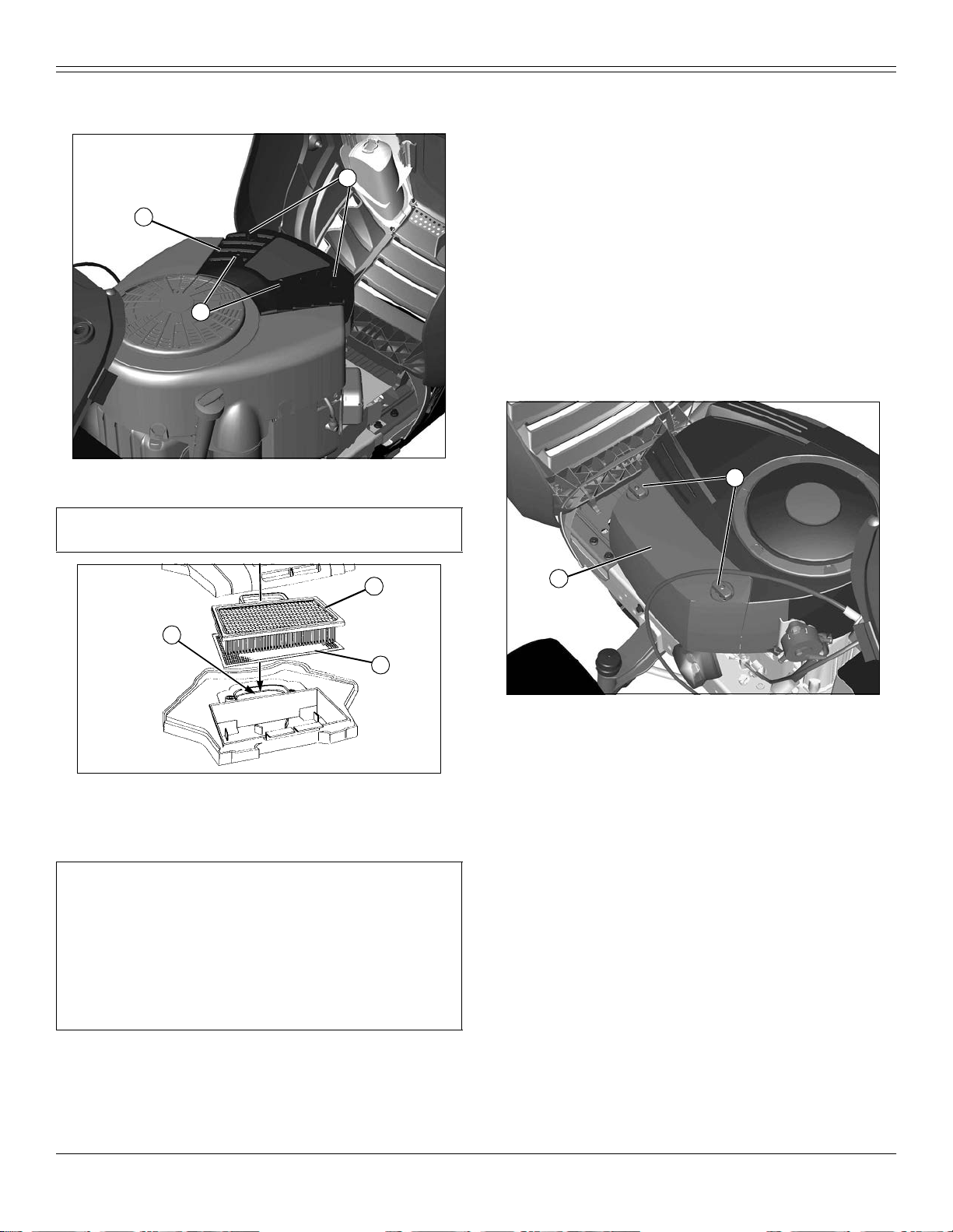
SERVICE ENGINE
3. Lift hood.
4. Clean dirt and debris from the air cleaner cover.
A
B
A
MX49397
5. Loosen four knobs (A) and remove cover (B).
IMPORTANT: Avoid damage! To prevent engine damage, do not
allow any foreign objects to fall into the carburetor air intake.
c.Rinse precleaner thoroughly. Squeeze out excess water in a dry cloth
until precleaner is completely dry.
9. Clean air cleaner housing carefully. Prevent any dirt from falling into
carburetor.
10. Install foam precleaner mesh side up.
11. Inst al l c artri dge. Ma k e s ure cartri dg e and se al are pr op erly se at ed an d
sealin g the carburetor air intake area.
12. Install air cleaner cover and tighten knobs. Do not overtighten.
13. Lo wer hood.
Checking and Cleaning Air Cleaner Elements (D120)
1. Park machine safely. (See Parking Safely in the SAFETY section.)
2. Let engine cool.
3. Lift hood.
4. Clean dirt and debris from the air cleaner cover.
A
D
C
E
M96094
6. Do not drop anything into the carburetor air intake (C). If anything falls
into the carburetor air intake it must be removed.
7. Lift out filter cartridge (D) and inspect it for damage.
IMPORTANT: Avoid damage! Dirt and debris can enter the engine
through a damaged filter element:
• Do not wash paper element.
• Do not attempt to clean paper element by tapping against
another object.
• Do not us e pressurized air to clean element.
• Replace element only if it is very dirty, damaged or the seal is
cracked.
B
MX49396
5. Loosen two knobs (A) and remove cover (B).
8. Inspect the foam precleaner (E) without removing it. If the foam
precleaner is dirty:
a.Remove it from the filter carefully.
b.Wash precleaner in a solution of warm water and liquid detergent.
Service Engine - 36
Page 38

SERVICE ENGINE
IMPORTANT: Avoid damage! Dirt and debris can enter the engine
through a damaged filter element:
• Do not wash paper element.
• Do not attempt to clean paper element by tapping against
another object.
• Do not us e pressurized air to clean element.
• Replace element only if it is very dirty, damaged or the seal is
cracked.
B
A
E
6. Pull filter assembly from air cleaner base (C). Inspect the foam
precleaner (D) without removing it . If the foam precleaner is dirty:
a.Remove it from the paper filter carefully.
b.Wash precleaner in a solution of warm water and liquid detergent. Do
not use oil.
c.Rinse precleaner thoroughly. Squeeze out excess water in a dry cloth
until precleaner is completely dry.
7. Inspect the paper filter element (E). If the paper filter element is
damaged or dirty, replace with new filter.
8. Clean air cleaner base very carefully, preventing any dirt from falling into
carburetor.
9. Ins tall foam precleaner on paper filter element.
10. Install new filter assembly back onto air cleaner base.
11. Install air cleaner cover and tighten two knobs.
12. Lo wer hood.
C
D
MX25902
Checking and Cleaning Air Cleaner Elements (D160 and D170)
1. Park machine safely. (See Parking Safely in the SAFETY section.)
2. Let engine cool.
3. Lift hood.
4. Clean dirt and debris from the air cleaner cover.
MX49394
5. Loosen two knobs (A) and remove cover (B).
IMPORTANT: Avoid damage! Dirt and debris can enter the engine
through a dam ag ed filter element:
• Do not wash paper element.
• Do not attempt to clean paper element by tapping against
anothe r objec t.
• Do not use pressurized air to clean element.
• Replace element only if it is very dirty, damaged or th e seal is
cracked.
E
C
D
MX25904
6. Pull filter assembly from air cleaner base (C). Inspect the foam
precleaner (D) without removing it. If the foam precleaner is dirty:
a.Remove it from the paper filter careful ly.
b.Wash precleaner in a solution of warm water and liquid detergent. Do
not use oil.
c.Rinse precleaner thoroughly. Squeeze out excess water in a dry cloth
until precleaner is completely dry.
7. Inspect the paper filter element (E). If the pape r filter element is
damaged or dirty, replace with new filter.
8. Clea n a i r cl ea ne r ba se v ery ca r eful l y, pre v e nti ng an y di rt fro m falling into
carburetor.
9. Install foam precleaner on paper filter element.
Service Engine - 37
Page 39

SERVICE ENGINE
10. Install new filter assembly back onto air cleaner base.
11. Install air cleaner cover and tighten two knobs.
12. Lo wer hood.
Checking and Cleaning Emission Filter (If Equipped)
1. Park machine safely. (See Parking Safely in the SAFETY section.)
B
A
MX39589
2. Inspect filter (A) for dirt and damage, wash or replace if required.
a.Remove cover (B) and remove emission filter (A) from under rear of
fend er deck.
b.Wash foam filter in a solution of warm water and liquid detergent. Do
not use oil.
c.Rinse filter thoroughly. Squeeze out excess water in a dry cloth until
filter is completely dry.
If foam filter cannot be cleaned properly or is damaged, replace with a
new filter.
d.Install foam air filter and secure with cover.
Checking Spark Plug
1. Park machine safely. (See Parking Safely in the SAFETY section.)
2. Let engine cool.
3. Lift hood.
5. Remove spark plug(s).
6. Clean spark plug carefully with a wire brush.
7. Inspect spark plug for:
• Crack ed porcelain.
• Pitted or damaged electrodes.
• Other wear or damage.
8. Replace spark plug as necessary .
B
M85200
9. Check plug gap (B) with a wire feeler gauge. To change gap, move the
outer electrode.
• Gap must be 0.76 mm (0.030 in.).
10. Install and tighten spark plugs to 20 N•m (15 lb-ft).
11. Connect spark plug wire(s) and lower hood.
Adjustin g C arburetor
NOTE: Carburetor is calibrated by the engine manufacturer and is
not adju stable.
If engine is operated at altitudes above 1829 m (6,000 ft), s ome
carburetors may r equire a special high altit ude main jet. See your
authorized dealer.
If engine is hard to start or runs rough, check the TROUBLE SHOOTING
section of this manual.
Possible engine surging will occur at high throttle with transmission in N
neutral and mower engagement lever disengaged. This is a normal
condition due to the emission control system.
After per fo rming the check s in the tro ub leshoot ing section an d you r engi ne
is still not performing correctly, contact your authorized dealer.
A
MX49394
Picture Note: Twin cylinder engine shown.
4. Disconnect spark plug wire(s) (A), one on each side on V-twin engines.
Service Engine - 38
Replacing Fuel Filter
NOTE: Change filter when fuel is low.
1. Park machine safely. (See Parking Safely in the SAFETY section.)
2. Let engine cool.
3. Lift hood.
4. Handle fuel safely. (See Handling Fuel Safely in the SAFETY section.)
5. Put a drain pan under fuel filter.
Page 40

SERV I C E TR ANSMISSION
A
B
MX13768b
6. Slide hose clamps (A) away from fuel filter (B) using a pliers.
7. Disconnect hoses from filter, and raise fuel lines vertically to avoid fuel
drainage.
IMPORTANT: Avoid damage! Incorrect installation of fuel filter
may cause engine damage. Install the filter with the arrow
pointing in the direction of fuel flow (towards the engine) for
proper operation.
8. Connect hoses to new filter making sure the filter arrow is pointed in the
direction of the fuel flow.
9. Install clamps and check for leaks.
10. Lo wer hood.
Service Transmission
c CAUTION: Avoid injury! Component is spring-assisted and
under tension. Injury can occur if spring-assisted component is
released suddenly.
C
A
B
MX25905
3. Put a 15 mm closed wrench or a socke t on the idler sheave nut (A) and
rotate clockwise to move idler sheave toward front of tractor and hold to
release belt tension.
4. Remove belt (B) fr om drive sheave (C), and release tension on sheave
nut (A).
5. To install the belt on the drive sheave, rotate idler sheave nut clockwise
to mov e idler sheave to ward front of tractor, and install belt on drive
sheave.
6. Release idler sheave nut to tighten belt.
Checking Transmi ssion
The transmission is a sealed componen t. No maintenance is required on
this transmission. If you suspect any transmission problems, please
contact your authorized dealer.
Service Mower
Removing or Installing Mower Drive Belt at Engine
Drive Sheave (122 cm (48 in.) and 137 cm (54 in.)
Mower Deck)
1. Park machine saf ely. (See Parking Safely in SAFETY section.)
2. Put lift lever in lowest position.
Removing Mower Deck
1. Park machine safely. (See Parking Safely in SAFETY sect io n.)
2. Put wood blocks under each side of mower deck.
3. Put attachment lift lever in lowest position, bringing mower deck down
onto blocks.
E
D
A
B
C
MX7681a
Picture Note: 107 cm (42 in.) mower deck only.
4. On mac hi nes w i th 1 07 cm (4 2 i n .), d iscon ne ct mo we r en ga ge me nt dr ive
Service Transm ission - 39
Page 41

SERVI C E MOW ER
cabl e (A) on left side of mower dec k.
a.Remove spring loc ki ng pi n (B ), p ul l a nd hold m o wer e nga ge ment dr iv e
cable out, lift up and remove from bracket (C).
b.Remove cable spring (D) from idler sheave bracket (E).
M
c CAUTION: Avoid injury! Mower lift arms can pinch fingers.
Lift arms are spring loaded and can snap back when deck is
removed.
Lock lift lever before pulling pin to remove mower deck.
F
F
H
G
MX16568
5. Remove spring locking pins and washers (F) and disconnect rear draft
arm (G) and adjustable lift links (H) on each side.
N
MX10514
Picture Note: 107 cm (42 in.) mower deck shown.
• On 107 cm (42 in.) mower deck only: Push mower engagement drive
cable into clip (M) and hook end of cable spring with hardware (N) into
peg on left side of machine frame.
Installing Mower Deck
1. Park machine safely. (See Parking Safely in SAFETY sect io n.)
2. Put attachment lift lever in the transport position.
3. Slide mower under machi ne.
4. Put wood blocks under each side of mower deck.
5. Put attachment lift lever in lowest position.
C
C
L
J
I
Picture Note: 107 cm (42 in.) mower deck shown.
6. Remove spring locking pin (I) and washer and front draft rod (J) from
mower deck bracket (K).
7. Remove mower drive belt from drive sheave (L).
8. Remove wood block s from both si de s and slide mower de ck ou t from
under the machine.
9. When operating the machine without the mower deck:
• Remove f ront draft rod from machine and attach it to the mower deck.
K
MX51680
B
A
MX16568
6. Fasten rear dra ft arm (A) and adjustable lift link (B), on each side, with
washers and spring locking pins (C).
Service Mower - 40
Page 42

SERVI C E MOW ER
IMPORTANT: Avoid damage! To prevent clutch da mage, make
sure front draft rod is installed correctly. Secure rod with washer
and spring locking pin on the left side of mower deck bracket.
F
D
G
Picture Note: 107 cm (42 in.) mower deck shown.
7. Install front draft rod (D) into mower deck bracket (E):
• For D105 models use the hole marked AUTO (shown).
• For all other models use the hole marked HYDRO (F).
8. Secure front draft rod with washer and spring locking pin (G).
E
MX51680
c CAUTION: Avoid injury! Component is spring-assisted and
under tensio n. Inju ry can occ ur if spr in g-a ss ist ed co mp one nt is
released suddenly.
J
MX51680
• On 107 cm (42 in.) mower deck: Make sure belt is routed through both
belt guides (J).
10. Remove wood blocks from both sides of mower deck.
11. On machines with 107 cm (42 in.) mower deck: Attach mower
engagement drive cable.
L
K
M
H
I
MX25905
Picture Note: 122 cm (48 in.) mower deck used for photo purposes.
9. Put mower drive belt on engine drive sheave (H).
• On 122 cm (48 in.) and 137 cm (54 i n.) mower dec k s: Put a 15 mm
closed wrench or a socket on the idler sheave nut (I) and rotate
clockwise, moving idler sheave and tensioning arm toward front of
tractor. Hold while installing belt on drive sheave.
Service Mower - 41
O
N
MX7681a
Picture Note: 107 cm (42 in.) mower deck only.
a.Route cable under mower belt and brake rod and attach cable spring
(K) to idler sheave bracket (L).
b.Pull out on cable (M), align black end of cable with slot in bracket (N)
and release cable in to slot. Secure with spring locking pin (O).
12. Level mower deck.
Replacing Mower Drive Belt (107 cm (42 in.) Mower Deck)
1. Park machine safely. (See Parking Safely in the SAFETY section.)
2. Remove mower deck.
3. Remove drive belt:
Page 43

SERVI C E MOW ER
A
a.Remove three capscrews and belt shield (A).
b.Remove two capscrews and belt shield (B).
c.Loosen sheaves (C).
d.Remove mower belt.
4. Ins pect belt for wear or damage; replace as necessary.
5. Clean top surface of mower deck and sheaves.
6. Install belt on mower deck as shown. Make sure belt is in the groove of
each sheave.
7. Tighten sheaves to 47 N•m (35 lb-ft).
8. Ins tall belt shields.
9. Install mower deck.
10. Adjust mower belt tension and spindle brakes, if n ecessary.
Replacing Mower Drive Belt (122 cm (48 in.) and 137 cm (54 in.) Mower Decks)
1. Park machine saf ely. (See Parking Safely in SAFETY section.)
2. Remo ve mower dec k.
C
B
MX25906
a.Loosen left side sheaves (B) and (C).
b.Remove mower b elt.
5. Inspect belt for wear or damage; replace as necessary.
6. Clean top sur face of mower deck and sheaves.
7. Install belt on mower deck as shown. Make sure belt is in the groove of
each sheave.
8. Tighten sheaves to 47 N•m (35 lb-ft).
9. Insta ll be lt sh ie ld s.
10. Install mower deck.
Adjusting Mower Belt Tension (107 cm (42 in.) Mower Deck)
1. Park machine safely. (See Parking Safely in the SAFETY section.)
2. Move mower engagement (PTO) lever or switch to OFF position.
B
A
MX7681a
3. Loosen nuts (A) and move cable bracket (B) away from the center of
mower deck to tighten belt tension. Move bracket until almost all slack is
out of cable but cable is not too tight. Tighten nuts.
Adjusting Spindle Brakes (107 cm (42 in.) Mower Deck)
C
B
A
Picture Note: 122 cm (48 in.) mower deck shown.
3. Remove five capscrews and left and right belt shields (A).
4. Remove drive belt.
c CAUTION: Avoid injury! The mower blades should stop in
approximately five seconds when the mower or PTO is
disengaged.
If you believe that your blades may not be stopping in that period
of time, take your machine to your authorized dealer where they
can safely check and service your machine.
IMPO RTANT: Avoid damage! Avoid belt damage.
Spindle brake engagement should be checked and corrected
every time the mower belt tension is adjusted.
Mower belt tension should be adjusted, if required, before brakes
are adj us ted.
MX25907
Service Mower - 42
1. Park machine safely. (See Parking Safely in the SAFETY section.)
2. Remove mower deck.
Page 44

SERVI C E MOW ER
A
A
MX25908
3. Remove left and right belt shields, and adjust two blade brakes (A).
B
C
MX25909
4. Measure distance from spindle brake bracket (B) to nut (C) on end of
brake rod.
• Bracket to nut distance should be: 2 - 3 mm (0.08 - 0.12 in).
5. If adjustment is required, turn nut (C) on end of brake rod in correct
direction to set brake at proper distance from pulley.
6. Adjust both brakes.
7. Install left and right belt shields.
8. Install mower deck.
MX4897
Picture Note: Mower deck with side discharge used for illustration
3. Measu re distance (A) between blade tip and flat ground surf ace.
4. Rotat e blade 180° and measure distance between other blade tip and
flat ground surface.
5. Install new blade if the difference between the two measurements is
more than 3 mm (1/8 in.).
6. Repeat for all blades.
Servicing Mower Blades
c CAUTION: Avoid injury! Rotating blades are dangerous.
Before adjusting or servicing mower:
• Disconnect spark plug wire(s) or battery negative (-) cable to
prevent engine from starting accidentally.
• Always wear gloves when handling mower blades or working
near bl ades.
Removing Mower Blades
1. Park machine safely. (See Parking Safely in SAFETY sect io n.)
2. Raise mower deck to gain access to mo wer blades. If necessary,
remove mower deck.
3. Block mower blade with a piece of wood to prevent it from sp inning.
Checking for Bent Mower Blades
c CAUTION: Avoid injury! Blades are sharp. Always wear
gloves when handling blades or working near blades.
Replace blades if defective. Never straighten or weld them.
1. Park machine safely. (See Parking Safely in the SAFETY section.)
2. Raise mower deck to highest position to access blades.
Service Mower - 43
D
B
A
4. Loosen and remove nut (A), washer (B), and blade (C).
C
MX16569
Page 45

SERVI C E EL ECT R I CA L
5. Inspect blades; sharpen, balance or replace blades as necessary.
Installing Mower Blades
1. Position mower blade (C) with the cutting edge towards the ground.
2. Align the splined center hole in the blade with the splined spindle shaft
(D) and put the blade onto the mower spindle shaft.
3. Install washer, with cupped side towards blade, and install nut to secure
blade onto splined spindle shaft.
4. Block mower blade with a piece of wood to prevent spinning and tighten
nut:
• Using 15/16 in. socket, tighten 5/8 in. blade nut to 88 N•m (65 lb-ft).
Sharpening Blades
c CAUTION: Avoid injury! Blades are sharp. Always wear
gloves when handling blades or working near blades.
Always wear safety eye protection when grinding.
• Sharpen blades with grinder, hand file, or electric blade sharpener.
A
B
• Keep origina l bevel ( A) wh en gr in di ng .
• Blade sho ul d have 0.40 mm (1/6 4 in . ) cut t in g ed ge (B) or les s.
• Balance blades before installing.
M61524
2. Put blade on nail in a vise. T u rn blade to horizontal position.
3. Check balance. If blade is not balanced, heavy end of blade will drop.
4. Grind bevel of heavy end. Do not change blade bevel.
Service Electrical
WARNING: Battery posts, terminals and related accessories contain lead
and lead components, chemicals known to the State of California to cause
cancer and reproductive harm. Wash hands after handling.
Service the Battery Safely
MIF
Balancing Blades
c CAUTION: Avoid injury! Blades are sharp. Always wear
gloves when handling blades or working near blades.
1. Clean blade.
Service Electrical - 44
c CAUTION: Avoid injury! The battery produces a flammable
and explosive gas. The battery may explode:
• Do not smo ke or have open flame near battery.
• Wear e ye protection and gloves.
• Do not allow direct metal contact across battery posts.
• Remove negative cable first when disconnecting.
• Install negative cable last when connecting.
Removing and Installing the Battery
Removing
1. Park machine safely and lift hood. (See Parking Safely in the SAFETY
Section.)
Page 46

SERVI C E EL ECT R I CA L
Using Booster Battery
A
B
C
MX49392
2. Disconnect negative (-) battery cable (A).
3. Push red cover (B) away from positive (+) battery terminal and remove
cable (C) from battery.
4. Remove battery.
Installing
1. Place battery into battery tray.
2. Connect positive (+) cable to positive (+) battery terminal first, then
negative (-) cable to negative (-) battery terminal.
3. Apply spray lubricant to terminal to help prevent corrosion.
4. Slide red cover over positive battery terminal.
Cleaning Battery and Terminals
1. Park machine safely. (See Parking Safely in the SAFETY section.)
2. Disconnect and remove battery.
3. Wash battery with solution of four tablespoons of baking soda to one
gallon of water. Be careful not to get the soda solution into the cells.
4. Rinse the battery wi th plain water and dry.
5. Clean terminals and battery cable ends w ith wire brush until bright.
6. Install battery.
7. Attach cables to battery terminals, beginning with the positive cable,
using washers and nuts.
8. Apply spray lubricant to terminal to prevent corrosion.
c CAUTION: Avoid injury! The battery produces a flammable
and explosive gas. The battery may explode:
• Do not smo ke or have open flame near battery.
• Wear e ye protection and gloves.
• Do not jump start or charge a frozen battery. Warm battery to
16°C (60°F).
• Do not connect the negative (-) booster cable to the negative
(-) terminal of the discharged battery. Connect at a good
ground location away from the discharged battery.
F
C
E
D
B A
M71044
A- Booster Battery
B- Disabled Vehicle Battery
1. Connect positive (+) booster cable to booster battery (A) positive (+)
post (C).
2. Connect the other end of positive (+) boo s ter cable to the disabled
vehicle battery (B) positive (+) post (D).
3. Connect negative (–) booster cable to booster battery negative (–) post
(E).
IMPORTANT: Avoid damage! Electric charge from booster battery
can damage machine components. Do not install negative
booster cable to machine frame. Install only to the engine block.
Install negative booster cable away from moving parts in the
engine compartment, such as belts and fan blades.
4. Connect the other en d (F) of negative (–) booster cable to a metal part
of the dis able d ma c hin e en gine block away from battery.
5. Start the engine of the disabled machine and run machine for several
minutes.
6. Carefully disconnect the booster c ables in the e xact rev erse order:
negative cable first and then the positive cable.
Replacing Headlight Bulb
1. Park machine safely. (See Parking Safely in the SAFETY section.)
2. Lift hood.
Service Electrical - 45
Page 47

SERVI C E MI SC ELLAN EO U S
A
MX46488
3. Turn bulb socket (A) 1/4 turn counterclockwise to remove.
4. Replace defective bulb with a new bulb.
5. Insert bulb socket into housing, push in and turn 1/4 turn clockwise to
install.
6. Lower hood.
Replacing Fuse
1. Park machine safely. (See Parking Safely in the SAFETY section.)
2. Lift hood.
Service Miscellaneous
Using Prop e r F uel and Stab ilize r
IMPORTANT: Avoid damage! Using stale, contaminated or
improper fuel can result in engine and fuel system damage.
Repairs caused by stale, contaminated or improper fuel are not
covered by wa rranty.
Use regular grade unleaded fuel with an octane rating of 87 octane or
higher. Fuel bl ends containing up to 10% ethanol or up to 15% MTBE
reformulated fuel are acceptable. Do not use fuel or additives containing
methanol as engine damage can occur.
Always use fresh, clean fuel that is purchased in a quantity that can be
used wit h in ap proximately 30 d a ys . F uel st ab il iz er sh ou ld a lw a y s b e a dd ed
to the fuel each time fuel is purchased. Add stabilizer before fi lling the fu el
container to insure proper mixing. Such practice helps prevent engine
performance proble ms and allows fuel storage in the machine all year
without draining.
Store fue l i n p la stic con t aine rs to red uce cond en sat ion . M ak e s ure th e ca p
on the fue l co nt ai ner is ti ght t o red uc e f ue l cont a min at ion and e v a po rat i on.
For best fuel storage life, use a self-sealing gas can.
Fuel is blended to give best seasonal performance. To avoid engine
performance problems such as hard starting or vapor lock, use in-season
fuel. Use fuel during warm weather that was purchased during that
season, and use fuel during cold weather that was purch ased during that
season.
Fuel can beco me sta le in mac hi ne s wit h en gine s th at are us ed seas on ally
or infrequently during a season. Stale fuel can produce varnish and plug
carburetor or EFI components which can affect engine performance.
Keep fuel storage container tightly covered and in a cool area out of direct
sunlig ht. Fuel can break down and degrade if not sealed properly or
exposed to sun and heat.
Condensation may collect in the fuel tank because of a variety of operating
or environmental conditions and, over time, may affect your machine’s
operation. Fill machine fuel tank at the en d of the day.
A
MX49392
3. Pull defective fuse (A) out of socket.
4. Check metal clip in fuse window and discard fuse if clip is broken.
5. Push new 20 amp fuse into socket.
6. Lower hood.
Service Miscellaneous - 46
Filling Fuel Tank
c CAUTION: Avoid injury! Fuel vapors are explosive and
flammable:
• Shut engine off before filling fuel tank.
• Allow engine to cool before refueling.
• Do not smoke while handling fuel.
• Keep fuel away from flames or sparks.
• Fill fuel tank outdoors or in well ventilated area.
• Clean up spilled fuel immediately.
• Use clean approved non-metal container to prevent static
electric discharge.
Page 48

SERVI C E MI SC ELLAN EO U S
IMPORTANT: Avoid damage! Dirt and water in fuel can cause
engine damage:
• Clean dirt and debris from the fuel tank opening.
• Use clean, fresh, stabilized fuel.
• Fill the fuel tank at the end of each day’s operation to keep
condensati on out of the fue l tank .
• Use a non-metallic funnel with a plastic mesh stra iner when
filling the fuel tank or container.
Fill fuel tank at the end of each day’s operation to prevent condensation
and freezing dur ing cold weather.
1. Park machine safely. (See Parking Safely in the SAFETY section.)
2. Allow engine to cool.
3. Remove any trash from area around fuel tank cap.
4. Remove fuel tank cap slowly to allow any pressure built up in tank to
escape.
5. Fill fuel tank only to bottom of filler neck. Do not overfill.
6. Do not continue to “top off” the tank once full.
7. Install fuel tank cap, and turn cap until it clicks.
Lifting Machine
1. Park machine safely . (See Parking Safely in the SAFETY section.)
c CAUTION: Avoid injury! The machine can fall or slip from
an unsafe lifting device or supports.
• Use a safe lifting device rated for the load to be lifted.
• Lower machine onto jack stands or other stable supports and
block wheels before servicing.
D
C
4. Safely lift front of machine at machine frame point (C). Place jack
stands or other stable supports under frame on each side at location (B).
5. If only lifting front of machine, block rear wheels remaining on ground to
avoid movement of machine.
6. To lower machine, lift front and/or rear of machine, and remove jack
stand s or su ppor ts. Low e r mac hi ne.
D
MX49387
Checking Tire Pressure
1. Check tires for damage.
2. Check tire pressure with an accurate gauge.
3. Service tires safely. (See Tire Safety in the SAFETY section.)
4. Check that tires have equal air pressure. Add or remove air, if
necessary.
5. Refer to side of tire for correct tire inflation pressure.
Removing and Installing Hood
Removing
B
A
Picture Note: Hydrostatic transmission model shown.
2. Safely lift rear of machine at machine frame point (A). Place jack stands
or other stable supports onto transaxle locations (B) where mounting bolts
for frame come through.
3. If only lifting rear of machine, block front wheels remaining on ground to
avoid moveme nt of ma c hine.
B
MX40761
Service Miscellaneous - 47
c CAUTION: Avoid injury! Touching hot surfaces can burn
skin. The engine, components, and fluids will be hot if the engine
has been running. Allow the engine to cool before servicing or
working near the engine and components.
IMPORTANT: Avoid damage! Do not operate machine with hood
open. Hood must be closed for proper engine cooling and
exhaust.
1. Park machine safely. (See Parking Safely in the SAFETY section.)
2. Let engine cool.
Page 49

SERVI C E MI SC ELLAN EO U S
Cleaning and Repairing Metal Surfaces
Cleaning:
Follow automotive practices to care for your vehicle painted metal
surfaces. Use a high-quality automotive wax regularly to maintain the
factory look of your vehicle’s painted surfaces.
Repairing Minor Scratches (surface scratch):
B
1. Clean ar e a to be re pa ir e d tho r ou gh ly.
IMPORTANT: Avoid damage! Do not use rubbing compound on
painted surfaces.
2. Use automotive polishing compound to remove surface scratches.
3. Apply wax to entire sur face.
A
MX46489
3. Open hood.
4. Disconnect wiring harness (A).
5. Appl y pres su re to “ Joh n” o n le ft s id e o f ho od a nd sl ow ly lo w er h oo d. L eft
side pivot should release after rotating closed approximately 45 degrees.
Once left side pivot releases, slide out right side pivot. Lo wer hood slightly
and lift hood from brackets (B).
Installing
1. Slid e r ight si de ho od pi v o t i nto tractor brac k et wit h ho od in open pos it i on
(left side pivot will slide into place as hood closes) and slowly close hood.
2. Connect wiring harness.
3. Close hood.
Cleaning Plastic Surfaces
IMPORTANT: Avoid damage! Improper care of machine plastic
surfa ces can damage that surface:
• Do not wipe plastic surfaces when they are dry. Dry wiping will
result in minor surface scratches.
• Use a soft, clean cloth (bath towel, diaper, automotive mitt).
• Do not use abrasive materials, such as polishing compounds,
on plastic surfaces.
Repairing Deep Scratches (bare metal or primer showing):
1. Clean area to be repaired with rubbing alcohol or mineral spirits.
2. Use paint stick with factory-matched colors available from your
authoriz e d de al er to fill scratches. F ol lo w dire ct ions inc lu de d on paint st ic k
for use and for drying.
3. Smooth out surface using an autom otive polish ing compound. Do not
use power buffer.
4. Apply wax to surface.
Removing and Installing Front Wheel Assembly
Removing:
1. Park machine safely. (See Parking Safely in the SAFETY section.)
c CAUTION: Avoid injury! The machine can fall or slip from
an unsafe lifting dev ice or suppo r ts .
• Use a safe lifting device rated for the load to be lifted.
• Lower machine onto jack stands or other stable supports and
block wheels before servicing.
IMPORTANT: Avoid damage! Place jack stands under frame, not
under transmission or engine, when raising or supporting
machine.
1. Rins e h ood a nd en tir e ma chin e w it h cl ea n w ate r t o r emo v e di rt and du st
that may scratch the surface.
2. Wash surface with clean water and a mild liquid automotive washing
soap.
IMPORTANT: Avoid damage! Insect repellent spray may damage
plastic and painted surfaces. Do not spray insect repellent near
machine.
3. Dry thoroughly to avoid water spo ts.
4. Wax the surface with a liquid automotive wax. Use products that
specifically say “contains no abrasives.”
IMPORTANT: Avoid damage! Do not use a power buffer to remove
wax.
5. Buff applied wax by hand using a clean, soft cloth .
Service Miscellaneous - 48
B
A
2. Safely lift and support machine. Place safe lifting device under end of
front hanger bracket at location (A), and place jack stands or other stable
supports under frame on each side at location (B). Block wheels
B
MX49387
Page 50

SERVI C E MI SC ELLAN EO U S
remaining on the ground to prevent machine movement.
C
M89737
3. Remove plastic cap (C) from end of wheel hub.
c CAUTION: Avoid injury! Components are installed under
spring tension. Wear eye protection and use proper tools when
installing and removing components with spring tension.
4. Install plastic cap (C ).
5. Safely remove jack stands and lower machine.
Removing and Installing Rear Wheel Assembly
Removing
1. Park machine safely. (See Parking Safely in the SAFETY section.)
c CAUTION: Avoid injury! The machine can fall or slip from
an unsafe lifting dev ice or suppo r ts .
• Use a safe lifting device rated for the load to be lifted.
• Lower machine onto jack stands or other stable supports and
block wheels before servicing.
IMPORTANT: Avoid damage! Place jack stands under frame, not
under transmission or engine, when raising or supporting
machine.
D
E
M89736
4. Remove snap ring (D) from end of axle.
5. Remove washer (E) and wheel from axle.
c CAUTION: Avoid injury! Explosive separation of tire and rim
parts is possible when they are serviced incorrectly:
• Do not attempt to mount a tire without th e proper equipment
and experience to perform the job.
6. Take wheel assembly to an authorize d service dealer for repairs.
Installing
1. Grease spindles and wheel hub grease fittings with specified grease.
2. Install wheel and washer (E) on axle.
3. Install snap ring (D).
B
2. Safely lift and support machine. Place safe lifting device under
transmission centered under machine frame point (A). Place jack stands
or other stable supports on each si de (B) where moun ting bolts for frame
come through. Block wheels remaining on the ground to prevent machine
movement.
E
C
D
3. Remove plastic cap (C), snap ring (D), and washer (E).
A
B
MX40761
H
F
G
MX16572
Service Miscellaneous - 49
Page 51

TROUBLESHOOTING
4. Remove wheel.
IMPORTANT: Avoid damage! Do not lose the shaft key. Key must
be installed for wheels to rotate and tractor to move.
5. Remove shaft key (F) (shown on end of transmission shaft), two
washer s (G ) , exce pt for mo del D105, and spac e r (H) .
c CAUTION: Avoid injury! Explosive separation of tire and rim
parts is possible when they are serviced incorrectly:
• Do not attempt to mount a tire without th e proper equipment
and experience to perform the job.
6. Take wheel assembly to an authorize d service dealer for repairs.
Installing
IMPORTANT: Avoid damage! Do not lose the shaft key. Key must
be installed for wheels to rotate and tractor to move.
NOTE: Rear wheels are installed with valves to the outside.
1. Install two washers (G), except on model D105, spacer (H), and shaft
key (F).
2. Install rear wheel, washer (E), snap ring (D) and plastic cap (C).
3. Safely rem ove ja ck sta n d s and low er m ac hine.
Troubleshooting
Using Troubleshooting C hart
If you are experiencing a problem that is not listed in this chart, see your
authorized dealer for ser vi c e.
When you have checked all the possible causes listed and you are still
experiencing the p roblem, see y our authorized dealer.
Engine
IF CHECK
Engine Will Not
Start
Engine Is Hard To
Start
Engine Runs
Unevenly
Engine Misses
Under Load
Engine Vapor
Locks
Brake pedal not de pressed.
Mower is engaged.
Spark plug wire is loose or disconnected.
Improper fuel.
Transmission is in reverse.
Plugged fuel filter.
Defective safety switch.
Electr ical pr ob le m - See E l ectr ica l Troub l es hoo tin g
Section
Carburetor is not adjusted properly or dirty.
Choke cable not adjusted properly.
Plugged fuel filter.
Faulty spark plug.
Stale or improper fuel.
Loose or corroded electrical connections.
Improper engine oil viscosity.
Cooling fins plugged.
Loose electrical connections.
Choke or thro t tl e ca ble stickin g.
Fuel line or fuel filter plugged.
Stale or dirty fuel.
Improper fuel.
Air cleaner element plugged.
Faulty spark plug.
Stale or dirty fuel.
Plugged fuel filter.
Fuel tank vent plugged.
Dirt in fuel filter.
Cooling fins plugged.
Loose hose connection at fuel filter or fuel pump.
IF CHECK
Poor Engine
Performance
Dirt in fuel system or fuel is old. Replace fuel with
fresh stabilized fuel. Obtain fuel from another
suppli er before suspecting machine problems.
Suppliers blend fuels differently and changing
suppli ers will gener ally solve any performance
problems.
Fuel blended with alcohol or ether may contribute
to performance problems by causing gum and
varnish deposits, especially if fuel is stored for
several weeks or more. Obtain fresh fuel .
Engine Overheats Engine air intake screen plugged.
Engine Will Not
Idle
Engine Knocks Stale or low octane fuel.
Engine Stops Or
Misses When
Operating On
Hillsides
Engine Backfires Faulty spark plug.
Troubleshooting - 50
Cooling fins plugged.
Engine oil low or too high.
Engine operated too long at a slow idle speed.
Spark plug not gapped correctly.
Faulty spark plug.
Opera tor raising off the seat.
Engine overloaded.
Low engine spe ed.
Oil level low.
Fuel tank less tha n half ful l of fue l.
Opera tor raising off of the seat.
Opera tor raising off of the seat.
Page 52

TROUBLESHOOTING
IF CHECK
Engine Loses
Power
Excessive Fuel
Consumption
Black Exhaust
Smoke
Engine St ops
When REVERSE
Foot Pedal Is
Depressed And
Attachment Is
Engaged
(Hydrostatic)
Engine St ops
When Automatic
Shift Lever Is
Moved To The R
(REVERSE)
Positio n an d
Attachment Is
Engaged
(Automatic)
Engine overheating.
Too much oil in engine.
Dirty air cleaner.
Faulty spark plug .
Travel speed is too fast for cond itions.
Improper fuel.
Choke is not fully open.
Air filter is dirty or oil soaked.
Choke partially engaged.
Normal condition. (See Using Reverse Implement
Option in the OPERATING section.)
Normal condition. (See Using Reverse Implement
Option in the OPERATING section.)
Electrical
IF CHECK
Starter Does Not
Work Or Will Not
T urn Engine
Battery Will Not
Charge
Lights Do Not
Work
Brake pedal is not depressed.
Mower is engaged.
Battery terminals are corroded.
Battery no t charge d .
Transmission is in reverse.
Blown fuse.
Fusible Link in starting circuit is blown - See your
author ized deal er
Dead cell in the battery.
Battery cables and terminals are dirty .
Low engine speed or excessive idling.
Light plug disconnected.
Loose or burned out bulb.
Tr actor
IF CHECK
Tractor Vibrates Too Much
Or Rattles Excessively
Tractor Will Not Move With
Engine Running
Attachment drive belts worn or damaged.
Traction drive belt damaged or worn.
Dirt on drive sheaves.
Blades bent or out of balance.
Parking brake locked.
Bypass rod is pulled out.
Mower
IF CHECK
Dischar ge Chute Plugged Travel speed too fast.
Grass too long.
Grass too wet.
Engine rpm not at wide open
throttle.
Restricted air flow.
Belt installed incorrectly.
Patches Of Grass Uncut Trave l speed too fast.
Engine rpm not at wide open
throttle.
Mower deck needs cleaning.
Belt Slipping Debris in sheaves .
Worn belt.
Belt tension is incorrect.
Too Much Vibration Debris on mower deck or in
sheaves.
Damaged drive belt.
Damaged sheaves or sheaves out of
alignment.
Blades out of balance.
Blades Scalping Grass Cutting too low.
Mower wheels not adjusted
correctly.
Turning spee d too fast.
Ridges in terrain.
Rough or uneven terrain.
Low tire pressure.
Mower Loads Down Tractor Engine rpm too low.
Travel speed too fast.
Debris wrapped around mower
spindles.
Troubleshooting - 51
Page 53

STORAGE
IF CHECK
Uneven Cut Mower deck not leveled properly.
Travel sp ee d too fast.
Blades dull.
Mower wheels not adjusted
correctly.
Tire pressure unequa l.
Mower (Or Other Attachment)
Stops When Vehicle Is Operated
in REVERSE
Normal condition. (See Using
Reverse Implement Option in the
OPERATING section.)
Storage
Stor ing Safety
c CAUTION: Avoid injury! Fuel vapors are explosive and
flammable. Engine exhaust fumes contain carbon monoxide and
can ca use serious illness or death:
• Run the engine only long eno ugh to move the machi ne to or
from storage.
• Machine fires and structure fires can occur if a machine is
stored before allowing it to cool, or if debris is not removed
from around the engine and muffler, or if stored near
combustible mat erials.
• Do not st ore vehicle with fuel in the tank inside a building
where fumes may reach an open flame or spark.
• Allow the engine to cool before storing the machine in any
enclosure.
Preparing Machine for Storage
1. Repair any worn or damaged parts. Replace parts if necessary . Tighten
loose ha rdw are .
2. Repair scratched or chipped metal surfaces to prevent rust.
3. Remove grass and debris from machine.
4. Clean under the deck and remov e grass and debris from inside chute
and bagg er.
5. Wash the machine and apply wax to metal and plastic surfaces.
6. Run machine for five minutes to dry belts and pulleys.
7. Apply light coat of engine oil to pivot and wear points to prevent rust.
8. Lubricate grease points and check tire pressure.
Preparin g Fu e l an d En gi ne Fo r St o ra g e
Fuel:
If y ou h a v e be en us ing “ St ab il i ze d Fu el ,” add stab il iz e d f u el t o t a nk un ti l the
tank is full.
NOTE: Filling the fuel tank reduces the amount of air in the fuel tank
and helps reduce deterioration of fuel.
If you are not using “Stabilized Fuel:”
1. Park machine safely in a well-ventilated area. (See Parking Safely in the
SAFETY section.)
NOTE: Try to anticipate the last time the machine will be used for the
season so very little fuel is left in the fuel tank.
2. Turn on engi ne and allow to run until it runs o ut of fuel.
3. For machines equipped with key switch, turn key to off position.
IMPORTANT: Avoid damage! Stale fuel can produce varnish and
plug carburetor or injector components and affect engine
performance.
• Add fuel conditioner or stabilizer to fresh fuel before filling tank.
4. Mix fresh fuel and fuel stabilizer in separate container. Follow stabilizer
instructions for mixing.
5. Fill fuel tank with stabilized fuel.
6. Run engine for a few minutes to allow fuel mixture to circulate through
carburetor on gas engi ne or fuel injectors on diesel engine.
Engine:
Engine storage procedure should be used when vehi cle is not to be used
for longer than 60 days.
1. Change engine oil an d filter while engine is warm.
2. Service air filter if necessary.
3. Clean debris from engine air intake screen .
4. On gas engines:
• Remove spark plugs. Put 30 mL (1 oz) of clean engine oil in
cylinder(s).
• Install spark plugs, but do not connect spark plug wires.
• Crank the engine five or six times to allow oil to be distributed.
5. Clean the engine and engine compartment.
6. Remove battery.
7. Clean the batt ery and battery posts. Check the electrolyte level, if your
battery is not maintenance free.
8. Close fuel shut-off valve, if your machine is equipped.
9. Store the battery in a cool, dry place where it will not freeze.
NOTE: The stored battery should be recharged every 90 days.
10. Charge the battery.
IMPORTANT: Avoid damage! Prolonged exposure to sunlight
could damage the hood surface. Store machine inside or use a
cover if stored outside.
11. Store the vehicle in a dry, protected place. If vehicle is stored outside,
put a waterproof cover over it.
Removing Machine From Storage
1. Check tire pressure.
2. Check engine oil level.
3. Check battery electrolyte level, if your battery is not maintenance free.
Charge battery if necessary.
4. Install battery.
5. On gas engines: Check spark plug gap. Install and tighten plugs to
specified torque.
6. Lubricate all grease points.
7. Open fuel shut-off valve, if your machine is equipped.
Storage - 52
Page 54

SPECIFICATIONS
8. Run the engine 5 minutes without the mower or any attachments
running to allow oil to be distributed throughout engine.
9. Be sure all shields and guards or deflectors are in place.
Specifications
Automatic Model D105
Manufacturer . . . . . . . . . . . . . . . . . . . . . . . . . . . . . . . Briggs & Stratton
Model Number . . . . . . . . . . . . . . . . . . . . . . . . . . . . . . . . . . . . . . 31G777
Power Rating Information. . . . . . http://www.briggsandstratton.com/
Displacement . . . . . . . . . . . . . . . . . . . . . . . . . . . . . . 500 cc (30.5 cu in.)
Bore . . . . . . . . . . . . . . . . . . . . . . . . . . . . . . . . . . . . . 90.68 mm (3.57 in.)
Stroke . . . . . . . . . . . . . . . . . . . . . . . . . . . . . . . . . . . .77.72 mm (3.06 in.)
Ignition Module (Armatu re)
Air Gap . . . . . . . . . . . . . . . . . . . . . . 0.253 - 0.356 mm (0.010 - 0.014 in.)
Intake Valve
Clearance . . . . . . . . . . . . . . . . . . . . 0.076 - 0.127 mm (0.003 - 0.005 in.)
Exhaust Valve
Clearance . . . . . . . . . . . . . . . . . . . . . .0.13 - 0.18 mm (0.005 - 0.007 in.)
Spark Plug-Gap . . . . . . . . . . . . . . . . . . . . . . . . . . . 0.76 mm (0.030 in.)
Spark Plug-Torque . . . . . . . . . . . . . . . . . . . . . . . . . . . 20 N•m (15 lb-ft)
Cylinders . . . . . . . . . . . . . . . . . . . . . . . . . . . . . . . . . . . . . . . . . . . . Single
Oil Filter . . . . . . . . . . . . . . . . . . . . . . . . . . . . . . . . . . . . . . . . . . . . . . . .Yes
Air Filter . . . . . . . . . . . . . . . . . . . . . . . . . . . . . . . . . . . . . . . . . . .Cartridge
Transmission . . . . . . . . . . . . . . . . . . . . . . . . . . . . . . . . . . . . . . Automatic
Transaxle Model . . . . . . . . . . . . . . . . General Transmission TM RT400
Travel Speed - Forward . . . . . . . . . . . . . . . . 0 - 8.9 km/h (0 - 5.5 mph)
Travel Speed - Reverse . . . . . . . . . . . . . . . . 0 - 4.8 km/h (0 - 3.0 mph)
Hydrostatic Mo de l D 11 0
Manufacturer . . . . . . . . . . . . . . . . . . . . . . . . . . . . . . . Briggs & Stratton
Model Number . . . . . . . . . . . . . . . . . . . . . . . . . . . . . . . . . . . . . . . 31P677
Power Rating Information. . . . . . . http://www.briggsandstratton.com
Displacement . . . . . . . . . . . . . . . . . . . . . . . . . . . . . . 500 cc (30.5 cu in.)
Bore . . . . . . . . . . . . . . . . . . . . . . . . . . . . . . . . . . . . . . 90.60 mm (3.56 in.)
Stroke . . . . . . . . . . . . . . . . . . . . . . . . . . . . . . . . . . . .77.78 mm (3.06 in.)
Ignition Module (Armatu re)
Air Gap . . . . . . . . . . . . . . . . . . . . . . 0.253 - 0.356 mm (0.010 - 0.014 in.)
Intake Valve
Clearance . . . . . . . . . . . . . . . . . . . . 0.076 - 0.127 mm (0.003 - 0.005 in.)
Exhaust Valve
Clearance . . . . . . . . . . . . . . . . . . . . . .0.13 - 0.18 mm (0.005 - 0.007 in.)
Spark Plug-Gap . . . . . . . . . . . . . . . . . . . . . . . . . . . 0.76 mm (0.030 in.)
Spark Plug-Torque . . . . . . . . . . . . . . . . . . . . . . . . . . . 20 N•m (15 lb-ft)
Cylinders . . . . . . . . . . . . . . . . . . . . . . . . . . . . . . . . . . . . . . . . . . . . Single
Oil Filter . . . . . . . . . . . . . . . . . . . . . . . . . . . . . . . . . . . . . . . . . . . . . . . Yes
Air Filter . . . . . . . . . . . . . . . . . . . . . . . . . . . . . . . . . . . . . . . . . . .Cartridge
Transmission . . . . . . . . . . . . . . . . . . . . . . . . . . . . . . . . . . . . Hydrostatic
Transaxle Model . . . . . . . . . . . . . . . . . . . . . . . . . . . . . . Tuff Torq™ T40
Travel Speed - Forward . . . . . . . . . . . . . . . . 0 - 8.9 km/h (0 - 5.5 mph)
Travel Speed - Reverse . . . . . . . . . . . . . . . . 0 - 5.2 km/h (0 - 3.2 mph)
Hydrostatic Model D120
Manufacturer . . . . . . . . . . . . . . . . . . . . . . . . . . . . . . . Briggs & Stratton
Model Number . . . . . . . . . . . . . . . . . . . . . . . . . . . . . . . . . . . . . . . 331877
Power Rating Informatio n . . . . . . . http://w ww.briggs an ds tr atto n.c om
Displacement . . . . . . . . . . . . . . . . . . . . . . . . . . . . . . . 540 cc (33 cu in.)
Bore . . . . . . . . . . . . . . . . . . . . . . . . . . . . . . . . . . . . . .94.02 mm (3.70 in.)
Stroke . . . . . . . . . . . . . . . . . . . . . . . . . . . . . . . . . . . . .77.78 mm (3.06 in.)
Ignition Module (Armature)
Air Gap . . . . . . . . . . . . . . . . . . . . . . 0.253 - 0.356 mm (0.010 - 0.014 in.)
Intake Valve
Clearance . . . . . . . . . . . . . . . . . . . . 0.076 - 0.127 mm (0.003 - 0.005 in.)
Exhaust Valve
Clearance . . . . . . . . . . . . . . . . . . . . . . 0.13 - 0.18 mm (0.005 - 0.007 in.)
Spark Plug-Gap . . . . . . . . . . . . . . . . . . . . . . . . . . . . 0.76 mm (0.030 in.)
Spark Plug-Torque . . . . . . . . . . . . . . . . . . . . . . . . . . . 20 N•m (15 lb-ft)
Cylinders . . . . . . . . . . . . . . . . . . . . . . . . . . . . . . . . . . . . . . . . . . . . Single
Oil Filter . . . . . . . . . . . . . . . . . . . . . . . . . . . . . . . . . . . . . . . . . . . . . . . Yes
Air Filter . . . . . . . . . . . . . . . . . . . . . . . . . . Cartridge w/foam precleaner
Transmission . . . . . . . . . . . . . . . . . . . . . . . . . . . . . . . . . . . . .Hydrostatic
Transaxle Model. . . . . . . . . . . . . . . . . . . . . . . . . . . . . . . Tuff Torq™ T40
Travel Speed - Forward . . . . . . . . . . . . . . . . 0 - 8.9 km/h (0 - 5.5 mph)
Travel Speed - Reverse . . . . . . . . . . . . . . . . . 0 - 5.2 km/h (0 - 3.2 mph)
Hydrostatic Models D130 and D140
Manufacturer . . . . . . . . . . . . . . . . . . . . . . . . . . . . . . . Briggs & Stratton
Model Number . . . . . . . . . . . . . . . . . . . . . . . . . . . . . . . . . . . . . . . 407777
Power Rating Informatio n . . . . . . . http://w ww.briggs an ds tr atto n.c om
Displacement . . . . . . . . . . . . . . . . . . . . . . . . . . . . . . 656 cc (40 cu in.)
Bore. . . . . . . . . . . . . . . . . . . . . . . . . . . . . . . . . . . . . . 75.44 mm (2.97 in.)
Stroke . . . . . . . . . . . . . . . . . . . . . . . . . . . . . . . . . . . . .73.41 mm (2.89 in.)
Ignition Module (Armature)
Air Gap . . . . . . . . . . . . . . . . . . . . . . 0.203 - 0.305 mm (0.008 - 0.012 in.)
Intake and Exhaust Valve
Clearance . . . . . . . . . . . . . . . . . . . . 0.102 - 0.152 mm (0.004 - 0.006 in.)
Spark Plug-Gap . . . . . . . . . . . . . . . . . . . . . . . . . . . . 0.76 mm (0.030 in.)
Spark Plug-Torque . . . . . . . . . . . . . . . . . . . . . . . . . . . 20 N•m (15 lb-ft)
Cylinders . . . . . . . . . . . . . . . . . . . . . . . . . . . . . . . . . . . . . . . . . . . . . Twin
Oil Filter . . . . . . . . . . . . . . . . . . . . . . . . . . . . . . . . . . . . . . . . . . . . . . . .Yes
Air Filter . . . . . . . . . . . . . . . . . . . . . . . . . Flat Panel w/Foam PreCleaner
Transmission . . . . . . . . . . . . . . . . . . . . . . . . . . . . . . . . . . . . .Hydrostatic
Transaxle Model . . . . . . . . . . . . . . . . . . . . . . . . . . . . . . Tuff Torq
Travel Speed - Forward . . . . . . . . . . . . . . . . . 0 - 8.9 km/h (0 - 5.5 mph)
Travel Speed - Reverse . . . . . . . . . . . . . . . . . 0 - 5.2 km/h (0 - 3.2 mph)
TM
T40
Hydrostatic Models D160 and D170
Manufacturer . . . . . . . . . . . . . . . . . . . . . . . . . . . . . . . Briggs & Stratton
Model Number (D160) . . . . . . . . . . . . . . . . . . . . . . . . . . . . . . . . . 44M777
Model Number (D170) . . . . . . . . . . . . . . . . . . . . . . . . . . . . . . . . . 44P777
Power Rating Informatio n . . . . . . . http://w ww.briggs an ds tr atto n.c om
Displacement . . . . . . . . . . . . . . . . . . . . . . . . . . . . . 724 cc (44.2 cu in.)
Bore . . . . . . . . . . . . . . . . . . . . . . . . . . . . . . . . . . . . . .79.25 mm (3.12 in.)
Stroke . . . . . . . . . . . . . . . . . . . . . . . . . . . . . . . . . . . . 73.41 mm (2.89 in.)
Ignition Module (Arm ature) Air Gap 0.203 - 0.254 mm (0.008-0.010 in.)
Specifications - 53
Page 55

SPECIFICATIONS
Intake and Exha us t V a lve Cl ear ance .0.102 - 0.152 mm ( 0 .004 - 0.0 06
in.)
Spark Plug-Gap . . . . . . . . . . . . . . . . . . . . . . . . . . . . 0.76 mm (0.030 in.)
Spark Plug-Torque . . . . . . . . . . . . . . . . . . . . . . . . . . . 20 N•m (15 lb-ft)
Cylinders . . . . . . . . . . . . . . . . . . . . . . . . . . . . . . . . . . . . . . . . . . . . . . Twin
Oil Filter . . . . . . . . . . . . . . . . . . . . . . . . . . . . . . . . . . . . . . . . . . . . . . . .Yes
Air Filter . . . . . . . . . . . . . . . . . . . . . . . . . Cartridge w/ Foam Precleaner
Transmission . . . . . . . . . . . . . . . . . . . . . . . . . . . . . . . . . . . . . Hydrostatic
Transaxle Model . . . . . . . . . . . . . . . . . . . . . . . . . . . .Tuff T orq™ HD K46
Travel Speed - Forward . . . . . . . . . . . . . . . . 0 - 8.9 km/h (0 - 5.5 mph)
Travel Speed - Reverse . . . . . . . . . . . . . . . . . 0 - 5.2 km/h (0 - 3.2 mph)
Electrical System
Charging System. . . . . . . . . . . . . . . . . . . . . . . . . . . . Regulated Circuit
Charging System Capacity (D100, D110, D120, D130, D140) . . 9 Amp
Charging System Capacity (D160, D170) . . . . . . . . . . . . . . . . . 16 Amp
Battery Voltage . . . . . . . . . . . . . . . . . . . . . . . . . . . . . . . . . . . . . . 12 Volts
Battery Type. . . . . . . . . . . . . . . . . . . . . . . . . . . . . . . . . . . . BCI Group U1
Capacities
Models D105, D110, D120
Crankcase, with Oil Filter . . . . . . . . . . . . . . . . . . . . . . . . 1.4 L (1.5 qt)
Models D130, D140, D160, D170
Crankcase, with Oil Filter . . . . . . . . . . . . . . . . . . . . . . . . 1.9 L (2.0 qt)
Fuel Tank . . . . . . . . . . . . . . . . . . . . . . . . . . . . . . . . . . . . . . . 9 L (2.4 gal)
Fuel System (All Models)
Fuel Types (Recommended):
. . . . . . . . . . . . . . . . . . . . . . . .Regular Grade 87 Octane Unleaded Fuel
. . . . . . . . . . . . . . . . . . . . . . . . . . . . . Ethanol Blended Fuel (Up to 10%)
. . . . . . . . . . . . . . . . . . . . . . . . . . MTBE Reformulated Fuel (Up to 15%)
Recommended Lubricants (All Models)
Engine Oil:
. . . . . . . . . . . . . . . . . . . . . . . . . . . . . . . . . . . . . . . . . . . . . TURF-GARD™
. . . . . . . . . . . . . . . . . . . . . . . . . . . . . . . . . . . . . . . . . . . . . . . . . . PLUS 4™
Grease:
. . . . . . . . . . . . . . . . . . John Deere Multi-Purpose SD Polyurea Grease
. . . . . . . . . . .John Deere Multi-Purpose HD Lithium Complex Grease
(Specifications and design subject to change without notice)
Weight: D110, D120 . . . . . . . . . . . . . . . . . . . . . . . . . . . . 204 kg (450 lb)
Weight: D130 . . . . . . . . . . . . . . . . . . . . . . . . . . . . . . . . . . 213 kg (470 lb)
Weight: D140, D160 . . . . . . . . . . . . . . . . . . . . . . . . . . . . . 238 kg (525 lb)
Weight: D170 . . . . . . . . . . . . . . . . . . . . . . . . . . . . . . . . . .262 kg (579 lb)
Tires
Models D105, D110, D120
Size (Front). . . . . . . . . . . . . . . . . . . . . . . . . . . . . . . . . . . . . . 15 x 6.00 - 6
Size (Rear) . . . . . . . . . . . . . . . . . . . . . . . . . . . . . . . . . . . . . . . 20 x 8.0 - 8
Tire Pressure (Front) . . . . . . . . . . . . . . . . . . . . . . . . . . . . 97 kPa (14 psi)
Tire Pressure (Rear) . . . . . . . . . . . . . . . . . . . . . . . . . . . . 69 kPa (10 psi)
Models D130, D140
Size (Front) . . . . . . . . . . . . . . . . . . . . . . . . . . . . . . . . . . . . . 15 x 6.00 - 6
Size (Rear) . . . . . . . . . . . . . . . . . . . . . . . . . . . . . . . . . . . . . 20 x 10.00 - 8
Tire Pressure (Front) . . . . . . . . . . . . . . . . . . . . . . . . . . . . 97 kPa (14 psi)
Tire Pressure (Rear) . . . . . . . . . . . . . . . . . . . . . . . . . . . . 69 kPa (10 psi)
Models D160, D170
Size (Front). . . . . . . . . . . . . . . . . . . . . . . . . . . . . . . . . . . . . . . 16 x 6.5 - 8
Size (Rear) . . . . . . . . . . . . . . . . . . . . . . . . . . . . . . . . . . . . . . 22 x 9.5 - 12
Tire Pressure (Front) . . . . . . . . . . . . . . . . . . . . . . . . . . . . 83 kPa (12 psi)
Tire Pressure (Rear) . . . . . . . . . . . . . . . . . . . . . . . . . . . . 83 kPa (12 psi)
(Tire pressure information is also located on the sidewalls of the tires)
Mower Deck - 107 cm (42 in.)
Blades Rotary. . . . . . . . . . . . . . . . . . . . . . . . . . . . . . . . . . . . . . . . . . . . . .2
Blade Nut Torque (w/ 5/8 in. Nut) . . . . . . . . . . . . . . . . 88 N•m (65 lb-ft)
Cutting Height (Approximately) . . . . . . . . . . . . 25 - 102 mm (1 - 4 in.)
Cutting Width . . . . . . . . . . . . . . . . . . . . . . . . . . . . . . . 1067 mm (42 in.)
Mower Deck - 122 cm (48 in.)
Blades Rotary. . . . . . . . . . . . . . . . . . . . . . . . . . . . . . . . . . . . . . . . . . . . . .3
Blade Nut Torque (w/ 5/8 in. Nut) . . . . . . . . . . . . . . . . 88 N•m (65 lb-ft)
Cutting Height (Approximately) . . . . . . . . . . . . . 25 - 102 mm (1 - 4 in.)
Cutting Width . . . . . . . . . . . . . . . . . . . . . . . . . . . . . . . .1219 mm (48 in.)
Mower Deck - 137 cm (54 in.)
Blades Rotary. . . . . . . . . . . . . . . . . . . . . . . . . . . . . . . . . . . . . . . . . . . . . .3
Blade Nut Torque (w/ 5/8 in. Nut) . . . . . . . . . . . . . . . . 88 N•m (65 lb-ft)
Cutting Height (Approximately) . . . . . . . . . . . . . 25 - 102 mm (1 - 4 in.)
Cutting Width . . . . . . . . . . . . . . . . . . . . . . . . . . . . . . . .1371 mm (54 in.)
Dimensions
Height (D105, D110). . . . . . . . . . . . . . . . . . . . . . . . . . . . 108 cm (42.5 in.)
Height (D120, D130). . . . . . . . . . . . . . . . . . . . . . . . . . . . 113 cm (44.5 in.)
Height (D140, D160, D170) . . . . . . . . . . . . . . . . . . . . . . 114 cm (45.0 in.)
Length (Overall) (D105, D110, D120, D130, D140) . 175 cm (68.75 in.)
Length (Overall) D160, D170) . . . . . . . . . . . . . . . . . . 176 cm (69.25 in.)
Width (Mower Deck Chute Down) (D 105, D110, D120 , D130) . .131 cm
(51.75 in.)
Width (Mower Deck Chute Down) (D140, D160) . . . . . . 152 cm (60 in.)
Width (Mower Deck Chute Down) (D170) . . . . . . . . . 174 cm (68.5 in.)
Weight: D105 . . . . . . . . . . . . . . . . . . . . . . . . . . . . . . . . . 200 kg (442 lb)
Specifications - 54
Page 56

WARRANTY
Warranty
Product Warranty
Product warranty is provided as part of John Deere’s support program for
custo m ers who operat e and maintain their equipment as described in this
manual.
Engine related warranties stated in this manual refer only to emissionsrelated parts and components of your engine. The complete engine
warranty, less emission-related parts and com ponents, is pr ovided
separately as the “Limited Warranty for New John Deere Equipment”.
California and U.S. EPA Emissions Control System Warranty Statement (Off-Road Gas Engines)
Y our Warranty Rights and Obligations
The California Air Resources Board, John Deere, and the United States
Environmental Protection Agency are pleased to explain the emi s sions
control system’s warranty on your model year 2013 or 2014 spark ignited
off-road engine equipment. In California, new equipment that uses small
or lar ge (l ess tha n 1 l ite r ) sp ark ign it ed off -r oa d engi ne s m us t be de si gn ed ,
built and equipped to meet the State’s stringent anti-smog standards. John
Deere m ust warrant the emissions control system on your spark ignit ed
off-road engine equipment for the period listed below provided there has
been no abuse, neglect or improper maintenance of your equipment.
Your emissions control sys tem may include parts such as: carburetor s or
fuel-injection system, ignition system, catalytic converters, fuel tanks,
valves, filter s , cla mp s, co nnecto rs, an d ot h er as s ociated com p on en t s.
Also included may be hoses, belts, sensors and other emission-related
assemblies.
Where a warrantable condition exists, John Deere will repair your spark
ignited off-road engine equipment at no cost to you including diagnosis,
parts and labor.
Manufacturer’s Warranty Cov era ge:
This em issi ons con tro l sy st em is wa rr an ted for two year s. If an y emis sion s
related part on your equipment is defective, the part will be repaired or
replaced by John Deere.
Owner’s Warranty R esponsibili ties:
• As the spark ignited off-road equipment owner, you are responsible for
the performance of the required maintenance listed in your Operator’s
Manua l. John Deere recommends that you retain all receipts covering
maintenance on your spark ignited off-road engine equipment, but John
Deere can not deny warranty solely for lack of receipts or for your failure to
ensure the performance of all scheduled maintenance.
• As the spark ignited off-road engine equipment ow ner, you s hould
however be aware that John Deere may deny you warranty coverage if
your spark ignited off-road equipment or a part has failed due to ab use,
negle c t, or improper maintenance or unapproved modifications.
• You are responsible for presenting your spark ignited off-road engine
equipment to an authorized John Deere Turf and Utility retailer as soon as
a problem exists. The warranty repairs should be completed in a
reasonable amount of time, not to exceed 30 days. If you have a question
regarding your warranty coverage, you should contact your John Deere
Turf and Utility retailer, or the Jo hn Deere Customer Contact Cent er at 1800-537-8233, or e-mail John Deere from www.Deere.com.
General Emissions Warranty Coverage:
The warranty period begins on the date the equipment is delivered to an
ultimate purchaser. John Deere warrants to the ultimate purchaser and
each subsequent purchaser that the spark ignited off-road engine
equipm e nt is :
• Designed, built and equipped so as to conform to all applicable
regulations adopted by the California Air Resources Boar d;
•Designed, built and equipped so as to conform at the time of sale with
applicable U.S. Environmen tal Protecti on Agency regulations under 40
CFR Parts 1054 and 1060: and,
• Free from defect s in materials and workmanship which cause such
engine to fa il to conform with applicable regulations for a period of two
years of engine use from the date of sale to the ultimate purch aser.
Emissions Warranty Interpretation
• Any warranted part that is not scheduled for replacement as required by
the maint e na nce inst ruct i on s i n th e Op erator’s Ma nual i s w ar ra nt e d f or tw o
years. If any such part fails during t he period of warranty coverage it will
be repaired or replaced by John Deere. Any such part repaired or
replaced under warranty is warranted for the remaining warranty period.
• Any warranted part tha t is scheduled only for regular inspection in the
maintenance instructions in the Operator’s Manual is warranted for two
years. A statement in the Operator’s Manual to the effect of “repair or
replace as necessary” does not reduce the period of warrant y coverage.
Any suc h part repaired or replaced under warranty is warranted for the
remaining warranty period.
• Any warranted part that is scheduled for replacement as required
maintenance in the Operator’s Manual is warranted for the period of time
prior to the fir st scheduled replacement point for that part. If the part fails
prior to the fir s t scheduled replacement, t he part will be repaired or
replaced by John Deere. Any such part repaired or replaced under
warranty is warranted for the remainder of the period prior to the first
schedul ed replacement point for the part.
• Repair or replacement of any warranted part under the warranty will be
performed at no charge to the owner at any au thorized John Deere Turf
and Utility retail er.
• The owner will not be charged for diagnostic labor which leads to the
determination that a warranted part is defective, pr ovided such work is
performed by John Deere.
• John Deer e wil l re pai r damag es to ot her eng i ne c ompon en ts proximately
caused b y a failure under warrant y of any emissions-related wa rranted
part.
• Add-on or modified parts that are not exempted by the California Air
Resources Board may not be used. The use of any non-exempted add-on
or modified parts will be grounds for disallowing a warranty claim. John
Deere will not be liable to warrant failures of warranted parts caused by
the use of a non-exempted add-on or modified part.
Emission Warranty Parts List
Coverage under thi s warranty extends only to the parts listed below (the
emissions control system parts) to the extent these parts were on the
engine and equipment purchased.
Fuel Metering System:
• Carburetor and internal parts (or fuel injection syste m ).
• Air/fuel ratio feedback and control system.
• Cold start en richment system.
Evaporative System:
• Fuel tank, fuel cap and tether.
• Fuel hose, line, fittings, clamps.
• Fuel pump, fuel shut-off valve.
• Fuel vapor hoses, fittings.
• Carbon canister.
• Rollover/slant valve for fuel vapor control.
• Purge and vent line.
Air Induction System:
• Air cleaner
• Intake manifold.
Warranty - 55
Page 57

WARRANTY
Ignition System:
• Spark plugs.
• Magneto or electronic ignition system.
• Spark advance/retard system.
Exhaust System:
• Exhaus t ma ni fold.
• Catalyst muffler.
Miscellaneous Items Used in Above Systems
• Vacuum and temp er a tur e swit ch es.
• Electronic controls.
• Hoses, belts, conn ec t o rs and assem b lie s.
Limited Liability
a) The lia bi lit y of Jo hn De ere u nd er t hi s Em is sions Con t ro l S ys te m
Warranty is limited solely to the remedying of defects in materials or
workmanship. This warranty does not cover inconvenience or l oss of use
of the non - road equ i pme nt or eng in e or t ran sp ortat io n of the eq ui pm ent or
engine to or from the John Deere Turf and Utility retailer. John Deere shall
not be liable for any other ex pense, loss, or damage, whether direct,
incidental, consequential (except as listed above under “coverage”) or
exemplar y arising in connect i on wi th the sale or us e of or ina bi lity to use
the non-road equipment or engine for any other purpose.
b) No express emissions control system warranty is given by John Deere
with r espe ct t o the eq ui pm en t and en gi ne ex ce pt as sp eci fic al ly se t f o rth in
this document. Any emissions control system warranty implied by law,
inclu ding any warranty of merchantability or fitness for a particular
purpose, is expressly limited to the emissions control system warranty
terms set forth in this document.
c) No dealer is authorized to modify this Federal, California and John
Deere Emissions Control System Warranty.
Tire Warranty
John Deere warranty applies for tires avai lable through the John Deere
parts system. For tires not available through the John Deere parts system,
the tire manufacturer’s warranty applicable to your machine may not apply
outsi de the U.S. (See your John Deere dealer for specific inf ormation.)
Limited Battery Warranty
NOTE: Applicable in North America only. For complete machine
warranty, reference a copy of the John Deere warranty statement.
Contact your John Deere dealer to obtain a copy.
is determined from the Warranty Code printed at the top of the battery and
chart below. Installation costs are not covered by warranty after 90 days
from the date of purchase.
THIS WARRANTY DOES NOT COVER
A. Breakage of the container, cover, or terminals.
B. Depreciation or damage caused by lack of reasonable and necessary
maintenance or by improper maintenance.
C. Transportation, mailing, or service call charges for warranty service.
LIMITATION OF IMPLIED WARRANTIES AND PURCHASER’S REMEDIES
To the extent permitted by law, neither John Dee re nor any company
affiliated with it makes any warranties, representations, or promises as to
the quality, performance or freedom from defect of the products cove red
by this warranty. IMPLIED WARRANTIES OF MERCHANTABILITY AND
FITNESS FOR A PARTICULAR PURPOSE, TO THE EXTENT
APPLICABLE, SHALL BE LIMITED IN DURA TION TO THE APPLICABLE
ADJUSTMENT PERIOD SET FORTH HERE. THE PURCHASER’S ONLY
REMEDIES IN CONNECTION WITH THE BREACH OR
PERFORMANCE OF ANY WARRANTY ON JOHN DEERE BATTERIES
ARE THOSE SET FORTH HERE. IN NO EVENT WILL THE DEALER,
JOHN DEERE OR ANY COMPANY AFFILIA TED WITH JOHN DEERE BE
LIABLE FOR INCIDENTAL OR CONSEQUENTIAL DAMAGES. (Note:
Some stat es do not al lo w l im itat i on s on ho w long an imp l ied w a rr ant y la st s
or the exclusion or limitation of incidental or consequential damages. So
these limi tat ions and e xclu sion s may no t apply to you. ) This w arrant y giv es
you specific legal rights, and you may also have some rights which vary
from sta t e to st at e.
NO DEALER WARRANT Y
The selling dealer makes no warranty of it’s o wn and the dealer has no
authority to make any representation or promise on behalf of John Deere,
or to modify the terms or limitations of this warranty in any way.
PRO RATA MONTHS OF ADJUSTMENT
NOTE: If your battery is not labeled with a warranty code, it is a
warranty code B.
Warranty Code Warranty Period
A 40 Months
B 36 Months
C 24 Months
TO SECURE WARRANTY SERVICE
The purchaser must request warranty service from a John Deere deal er
authorized to sell John Deere batteries, and present the battery to the
dealer with the top cover plate codes intact.
FREE REPLACEMENT
Any new batte ry which bec om es unservic ea ble (not merel y dis c ha r ge d )
due to defects in ma te r i al or wor k m an s hip wi th in 90 days of pu r ch a se wil l
be replaced free of charge. Installation costs will be covered by warranty if
(1) the unserviceable battery was installed by a John Deere factory or
dealer, (2) failure occurs within 90 days of purchase, and (3) the
replacement batte ry is installed by a Joh n Deere dealer.
PRO RATA ADJUST MENT
Any new batte ry which bec om es unservic ea ble (not merel y dis c ha r ge d )
due to defects in material or workmanship more than 90 days after
purchase, but before the expiration of the applicable adjustment period,
will be replaced upon payment of the battery’s current list price less a pro
rata c r edit for unused mo nt h s of s ervi ce . T he ap pl ic abl e ad ju stmen t pe riod
Warranty - 56
Page 58

INDEX
Index
A
Accessories, Using ................................................................................31
Air Cleaner Elements (D105 and D110), Checking and Cleaning
Air Clean er Ele m en t s (D120), Ch ec k ing and Cl ea nin g
Air Cleaner Elements (D130 and D140), Checking and Cleaning
Air Cleaner Elements (D160, D170), Checking and Cleaning
Air Cleaner Elements (Single Cylinder Briggs and Stratton), Checking and
Cleaning
Air Intake Screen, Cleaning
Attachment Engagement Switch or Lever, Testing
Automatic Transmission, Using Travel Controls on
Axle, Lubricating Front
B
Bagger, Unplugging ...............................................................................29
Balancing Blades
Battery and Terminals, Cleaning
Batter y, Charge and C onnect at Assem bly
Battery, Removing and Installing
Battery, Service Safely
Battery, Using Booster
Belt, Adjusti ng Tens io n (10 7 cm (42 in .) Mo wer D eck)
Belt, Installing and Removing Mower Drive at Engine Drive Sheave (122
cm (48 i n.) and 137 (54 in.) Decks)
Belt, Replacing Mower Driv e (107 cm (42 in.) Mower Deck)
Belt, Replacing Mower Drive (137 cm (54 in.) and 137 cm (54 in.) Decks)
42
Blades, Balancing
Blades, Checking Mower
Blades, Servicing Mower
Blades, Sharpening
Brake Switch, Testing Park
Brake, Testing Park
Brake, Using Park
Bulb, Replacing Headlight
C
Capacities .............................................................................................. 54
Carburetor, Adjusting
Certification Label
Controls on Automatic Transmission, Using Travel
Controls on Hydrostatic Transmission, Using Travel
Controls, Operator Station (D105)
Controls, Operator Station (D110, D120, D130)
Controls, Operator Station (D140, D160, D170)
Cruise Control, Using
Customer Service
Cutting Height, Adjustin g
D
Daily Operating Checklist ......................................................................21
Deck, Adjusting Mower Level
Deck, Installing Mower
Deck, Removing Mower
Dimensions, Machine
E
Electrical Specifications .........................................................................54
Electrical Troubleshooting
Emission Compliance Period
Emission Control System Certification Label
Emission Filter, Checking and Cleaning
Engagement Clutch, Break In Electric
................................................................................................. 36
................................................................... 35
........................................................................... 32
................................................................................... 44
...........................................................45
............................................16
........................................................... 44
.......................................................................... 44
........................................................................... 45
....................................................... 39
.................................................................................. 44
....................................................................... 43
....................................................................... 43
............................................................................... 44
....................................................................24
...............................................................................24
..................................................................................25
.....................................................................45
............................................................................. 38
.................................................................................... 7
......................................................... 18
.............................................................................28
.................................................................................. 57
....................................................................... 21
................................................................ 21
........................................................................... 40
......................................................................... 39
............................................................................ 54
.....................................................................51
................................................................... 7
........................................... 6
................................................ 38
................................................... 16
.......................... 36
................................24
............................... 26
.......................... 42
............................... 26
............................. 27
....................................19
....................................20
......... 35
......... 35
............... 37
.................41
Engine Fins, Cleaning
Engine Oil
Engine Oil Level, Checking
Engine Oil and Filter, Changing
Engine Specifications
Engine Troubleshooting
Engine W arr a nt y Mainte na nc e St a tem e n t
Engine and Fuel Storage, Preparing
Engine, Idl in g
Engine, Starting
Engine, Stopping
F
Filter, Changing Engine Oil ....................................................................34
Filter, Checking and Cleaning Emission
Filter, Replacing Fuel
Front Axle, Lubricating
Front Wh eel Assembly, Removing and Installing
Fuel Filter, Replacing
Fuel Safety
Fuel Storage
Fuel Tank, Filling
Fuel Types Recommended
Fuel, Using Proper
Fuse, Replacing
G
Grease ...................................................................................................32
H
Headlight Bulb, Replacing ......................................................................45
Headlights, Using
Hood, R em ov in g and Insta ll ing
Hourmeter, Using
I
Identific a tio n N umbe r s ..............................................................................1
K
Key Swit c h, Using ..................................................................................25
L
Label, Certification ...................................................................................7
Labels, Safety (No Text)
Labels, Safety (Text)
Leveling Mower Deck
Lifting Machine
Literatur e, Serv ic e
Lubricants, Recommended
M
Mach in e, Li f ti ng ......................................................................................47
Machine , Moving by Hand
Machine , Transporting on Trailer
Material Collection System, Unplugging
Metal Surfaces, Repairing and Cleaning
Moving Ma chine by Hand
Mower Blades, Checking
Mower Blades, Choosing
Mower Blades, Servicing
Mower D ec k 122 cm (48 in.), Speci fic a tio ns
Mower D ec k 137 cm (54 in.), Speci fic a tio ns
Mower Deck Level, Adjusting
Mower Deck, Adjusting Belt Tension (107 cm (42 in.) Deck)
Mower Deck, Adjusting Cutting Height
Mower Deck, Adjusting Spindle Brakes (107 cm (42 in.) Deck)
Mower Deck, Adjusting Wheels
Mower Deck, Cleaning
Mower Deck, Drive Belt Replacement (107 cm (42 in.) Deck)
...............................................................................................33
.............................................................................................13
...........................................................................................52
............................................................................35
....................................................................33
.............................................................34
.............................................................................53
.........................................................................50
..............................................33
......................................................52
.........................................................................................26
......................................................................................26
....................................................................................26
.................................................38
.............................................................................38
...........................................................................32
...................................48
.............................................................................38
....................................................................................46
....................................................................54
.................................................................................46
.....................................................................................46
...................................................................................25
..............................................................47
...................................................................................25
...........................................................................4
................................................................................3
.............................................................................21
.......................................................................................47
..................................................................................56
....................................................................54
......................................................................29
...........................................................29
.................................................29
................................................48
.......................................................................29
........................................................................43
.......................................................................31
........................................................................43
..........................................54
..........................................54
.................................................................21
.................42
...................................................21
..............................................................23
...........................................................................28
.............42
...............41
Index - 57
Page 59

GETTING QUALITY SERVICE
Mower Deck, Drive Belt Replacement (122 cm (48 in.) and 137 cm (54 in.)
Decks)
....................................................................................................42
Mower Deck, Engaging and Disengaging
Mower Deck, Installing Deck
Mower Deck, Lubricating Pivot Points
Mower Deck, Removing Deck
Mower Deck, Removing and Installing Drive Belt at Engine Sheave (122
cm (48 i n.) and 137 (54 in.) Decks)
Mower Deck, Specifications (107 cm (42 in.)
Mower Deck, Unplugging
Mower Troubleshooting
Mowing Tips
...........................................................................................31
................................................................. 40
............................................................... 39
....................................................................... 29
.........................................................................51
..............................................28
................................................... 32
....................................................... 39
........................................ 54
O
OMGX22464J6 ........................................................................................0
Oil Level, Checking Engine
Oil and Fil ter , Chan ging Engi ne
Oil, Engine
Operating Checklist, Daily
Operator Station Controls (D105)
Operator Station Controls (D110, D120, D130)
Operator Station Controls (D140, D160, D170)
............................................................................................. 33
....................................................................33
.............................................................34
.....................................................................21
.......................................................... 18
.....................................19
.....................................20
P
Park Brake, Testing ...............................................................................24
Park Brake, Testing Switch
Park Brake, Using
Parts Catalog
Parts, Replacement
Plastic And Painted Surfaces, Avoid Damage To
Plastic Surfaces, Cleaning
..................................................................................25
.........................................................................................56
....................................................................24
...............................................................................56
..................................21
.....................................................................48
R
Rear Wh eel Assembly, Removing and Installing ................................... 49
Reverse Implement Option, Testing
Reverse Implement Option, Using the
......................................................25
................................................... 27
S
Safety Label Location (No Text) .............................................................. 4
Safety Label Location (Text)
Safety Systems, Testing
Safety, Tire
Seat Switch, Testing
Seat, Adjusting
Service Intervals
Service Literature
Service Reminder, Using
Sharpening Blades
Spark Arrestor, Using
Spark Plug, Checking
Specifications
Specifications, 107 cm (42 in.) Mower Deck
Spindle Brakes 107 cm (4 2 in.) Mower Deck, Adjusting
Stablizer, Using Proper Fuel
Stopping Engine
Storag e, Pre pa ring Fuel an d Eng in e f or
Storage, Preparing Machine for
Storage, Removing Machine from
Storing Safety
............................................................................................13
....................................................................................... 21
.................................................................................... 32
................................................................................... 56
................................................................................44
.........................................................................................53
.................................................................................... 26
........................................................................................52
.................................................................... 3
........................................................................ 24
..............................................................................24
....................................................................... 25
..............................................................................9
............................................................................38
.......................................... 54
........................42
.................................................................. 46
................................................ 52
.............................................................52
......................................................... 52
T
Techni cal Manu al ...................................................................................56
Testing Safety Systems
Tire Chains, Using
Tire Pre ssure, Checking
Tire Specifications
Tractor Troubleshooting
Transmission, Checking (See your John Deere dealer)
.........................................................................24
................................................................................. 30
........................................................................ 47
.................................................................................54
......................................................................... 51
........................ 39
Transporting Machine on Trailer
Travel C ontrols on Hydr ostatic Transmission, Using
Troubleshooting Chart
............................................................................50
............................................................29
.............................27
W
Warra n ty Mainte na nc e St a tem e n t , En gi ne .............................................33
Warranty Registration, Refer to the Production Identification Section
Warrant y, Product
Wash Port, Usin g
Weights, Using
Wheel Assembly, Removing and Installing Front
Wheel Assembly, Removing and Installing Rear
Wheels, Adjusting Mower Deck
..................................................................................55
...................................................................................28
.......................................................................................30
...................................48
...................................49
..............................................................23
.....2
Getting Quality Service
Service Literature
If you would like a copy of the Parts Catalog or T echnical Manual for this
machine call:
• U.S. & Canada: 1-800-522-7448.
• All Other Regions: Your John Deere dealer.
Parts
We recommend John Deere quality parts and lubricants, available at your
John Deere dealer.
When you o r de r parts, y ou r Joh n D eer e d ea ler nee ds the se ri al n umb er or
product identification number (PIN) for your machine or attachment. These
are the numbers that you recorded in the Product Identification section of
this manual.
Order Service Pa rts Online
Visit http://JDParts.deere. com for y our Internet co nnection to parts
ordering and information.
John Deere Quality Continues with Quality Service
John Deere provides a process to handle your quest ions or problems,
should they arise, to ensure that product quality continues with your John
Deere de aler’s parts and service support.
Follow the steps below to get answers to any questions you may have
about your product .
1. Refer to the appropriate attachment, machine or equipment operator
manuals.
2. Contact your John Deere dealer with unanswered questions.
3. In North America or Canada, call the John Deere Customer Contact
Center.
• Call 1-800-537-8233 and provide product serial number and model
number.
Getting Quality Service - 58
Page 60

Service Record
Record Service Dates
SERVICE RECORD
Oil Change Oil Filter Change
(If Equipped)
Lubricate
Machine
Air Cleaner
Element Check/
Clean
Fuel Filter
Change
Service Record - 59
Page 61

SERVICE RECORD
Service Record - 60
Page 62

SERVICE RECORD
Service Record - 61
 Loading...