

Page 1

Series 400
6076
Diesel Engines
Serial Number
(500000- )
COMPONENT TECHNICAL MANUAL
pЙкбЙл=QMM=SMTS=aбЙлЙд=bеЦбеЙл=pЙкб~д
kмгДЙк=ERMMMMMJ=F
`qjQO=EOQj^oVRF=====bеЦдблЬ
DCTCTM4 2 24MAR9 5
Deere Power Systems Group
CTM42 (24MAR95)
LITHO IN U.S.A.
ENGLISH
Page 2

FOREWORD
Introduction
This manual is written for an experienced technician.
Essential tools required in performing certain service
work are identified in this manual and are
recommended for use.
Live with safety: Read the safety messages in the
introduction of this manual and the cautions
presented throughout the text of the manual.
This is the safety-alert symbol. When you see
N
this symbol on the machine or in this manual,
be alert to the potential for personal injury.
Use this component technical manual in conjunction
with the machine technical manual. An application
listing in the introduction identifies
product-model/component type-model relationship.
See the machine technical manual for information on
component removal and installation, and gaining
access to the components.
This manual is divided in two parts: repair and
operation and tests. Repair sections contain
necessary instructions to repair the component.
Operation and tests sections help you identify the
majority of routine failures quickly.
Information is organized in groups for the various
components requiring service instruction. At the
beginning of each group are summary listings of all
applicable essential tools, service equipment and
tools, other materials needed to do the job, service
parts kits, specifications, wear tolerances, and torque
values.
Component Technical Manuals are concise service
guides for specific components. Component technical
manuals are written as stand-alone manuals covering
multiple machine applications.
Fundamental service information is available from
other sources covering basic theory of operation,
fundamentals of troubleshooting, general
maintenance, and basic type of failures and their
causes.
DX,CTMIFC -19-22MAY92
CTM42 (24MAR95) 6076 Diesel Engines—S.N. (500000— )
160101
PN=3
Page 3
Page 4

Page 5

Dealer Presentation Sheet
JOHN DEERE DEALERS
IMPORTANT: The changes listed below make your
current CTM obsolete. Discard
CTM42, dated 02 NOV 92. Please
copy this page and route through
your service department.
• Engine application charts updated to include the
latest product models. See ENGINE APPLICATION
CHART in Group 01.
• Engine coolant information revised. See ENGINE
COOLANT RECOMMENDATIONS in Group 02.
• Recommendation to use ONLY JDG23 Lifting Sling
and Deere provided lifting straps for lifting engines.
Also recommend the use of SAE Grade 8 or higher
grade cap screws and Loctite 242 when installing
engine lifting straps added to Group 03.
• New “TORQUE-TO-YIELD” instructions for tightening
cylinder head cap screws marked “SPECIAL” added
to Group 05.
• Valve lift specifications revised in Group 05 and
Group 16.
• Piston ring end gap specifications for new pistons
have been added to Group 10.
• A revised (longer) JDG681A Tap for cleaning
deeper tapped cylinder head cap screw holes in block
added to Group 10.
• Recommendation against disassembly of the engine
oil pump added to Group 20.
• Instructions for installation of structural front
frame/oil sump on engines used in 8000 series
tractors added to Group 20.
• Information and specifications for fan drive assembly
with press-fit fan spacer added to Group 25.
• Torque specifications for turbocharger oil inlet line
added to Group 30.
• Information to help identify A-Series and P-Series
fuel injection pumps and fuel supply pumps added to
Group 35.
• Instructions for disassembly and assembly of the
fuel check valve deleted from Group 35. The check
valve has been replaced by a non-serviceable
assembly.
• In Group 100 — Engine Tune-Up and Break-In, the
paragraph titled ALTITUDE COMPENSATION
GUIDELINE changed to EFFECTS OF
TEMPERATURE AND ALTITUDE ON ENGINE
PERFORMANCE.
• In Group 105, the recommended temperatures and
engine speeds for checking engine oil pressure
revised. The procedure to pressure test the cooling
system and radiator cap also revised.
• Use of JDG796 Alignment Tool for installing
crankshaft rear oil seal housing added to Group 15.
• Detailed instructions for inspection of the vibration
damper and the crankshaft dowel pin added to Group
15.
• Timing gear cover and rear oil seal housing
replacement procedures for 6076HRW33, 34, and 35
Engines (equipped with structural front frame/oil
sump), with engine installed in vehicle added to
Group 15.
• Camshaft lobe lift specifications and valve lift
specifications revised in Group 16.
TIME TRAC® is a registered trademark of Stanadyne Automotive Corp.
CTM42 (24MAR95) 6076 Diesel Engines—S.N. (500000— )
• Dynamic timing procedure using TIME TRAC
timing kit to accurately check and adjust (rotary)
injection pump-to-engine timing added to Group 115.
• Instructions and specifications for check and
adjustment of the fuel shut-off solenoid added to
Group 115.
• Instructions for changing 6076 generator set
engines with mechanical governor from rated speed
of 1800 RPM (60 Hz) to 1500 RPM (50 Hz) added to
Group 115.
RG,CTM42,DPS -19-21MAR95
®
160101
PN=4
Page 6

ABOUT THIS MANUAL
This component technical manual covers the
recommended repair procedure for 6076, 7.6 L (466
cu. in.) diesel engines produced in Waterloo, Iowa
beginning with Engine Serial No. (500000— ).
Before beginning repair of an engine, clean the
engine and mount on a repair stand. (See Group 03 Engine Mounting.)
Direction of engine crankshaft rotation in this manual
is referenced facing the flywheel looking toward the
fan. Front of engine is fan drive end.
Some components of this engine may be serviced
without removing the engine from the machine. Refer
to the specific machine technical manuals for
information on components that can be serviced
without removing the engine from the machine and
for engine removal and installation procedures.
Read each module completely before performing any
service.
RG,CTM42,G0,1 -19-14FEB95
CTM42 (24MAR95) 6076 Diesel Engines—S.N. (500000— )
160101
PN=5
Page 7

Contents
Page
Group 00—Safety
Safety . . . . . . . . . . . . . . . . . . . . . . . . . . . 00-1
Group 01—General Information
Unified Inch Bolt and Cap Screw Torque
Values . . . . . . . . . . . . . . . . . . . . . . . . . 01-1
Metric Bolt and Cap Screw Torque
Values . . . . . . . . . . . . . . . . . . . . . . . . . 01-2
Engine Model Designation . . . . . . . . . . . . . . 01-3
Engine Serial Number Plate Information . . . . . 01-4
Engine Application Chart . . . . . . . . . . . . . . . 01-5
Engine Application Chart . . . . . . . . . . . . . . . 01-6
Group 02—Fuels, Lubricants, and Coolant
Diesel Fuel . . . . . . . . . . . . . . . . . . . . . . . . 02-1
Lubricity of Diesel Fuels . . . . . . . . . . . . . . . 02-1
Engine Break-In Oil . . . . . . . . . . . . . . . . . . 02-2
Engine Oil . . . . . . . . . . . . . . . . . . . . . . . . 02-3
Oilscan and Coolscan . . . . . . . . . . . . . . . . . 02-4
Grease . . . . . . . . . . . . . . . . . . . . . . . . . . . 02-4
Alternative and Synthetic Lubricants . . . . . . . 02-5
Engine Coolant Requirements . . . . . . . . . . . 02-5
Recommended Engine Coolant . . . . . . . . . . . 02-7
Engine Coolant Specifications . . . . . . . . . . . 02-8
Replenish Supplemental Coolant
Additives Between Coolant Changes . . . . 02-10
Operating in Tropical Conditions . . . . . . . . . 02-11
Flush and Service Cooling System . . . . . . . 02-12
Disposing of Coolant . . . . . . . . . . . . . . . . 02-13
Group 03—Engine Mounting
Engine Repair Stand . . . . . . . . . . . . . . . . . 03-1
Safety Precautions . . . . . . . . . . . . . . . . . . . 03-2
Install 400 Series Adapters on Repair
Stand . . . . . . . . . . . . . . . . . . . . . . . . . . 03-2
Engine Lifting Procedure . . . . . . . . . . . . . . . 03-3
Clean Engine . . . . . . . . . . . . . . . . . . . . . . 03-4
Disconnect Turbocharger Oil Inlet Line . . . . . 03-4
Mount Engine On Repair Stand . . . . . . . . . . 03-5
Page
Group 04—Engine Rebuild Guide
6076 Engine Disassembly Sequence . . . . . . . 04-1
Sealant Application Guidelines . . . . . . . . . . . 04-2
6076 Engine Assembly Sequence . . . . . . . . . 04-4
Group 05—Cylinder Head and Valves
Special or Essential Tools . . . . . . . . . . . . . . 05-1
Service Equipment and Tools . . . . . . . . . . . . 05-3
Other Material . . . . . . . . . . . . . . . . . . . . . . 05-4
Cylinder Head and Valves Specifications . . . . 05-5
Check and Adjust Valve Clearance . . . . . . . . 05-7
Check Valve Lift . . . . . . . . . . . . . . . . . . . . 05-9
Remove Cylinder Head . . . . . . . . . . . . . . . 05-10
Disassemble and Inspect Rocker Arm
Shaft Assembly . . . . . . . . . . . . . . . . . . 05-12
Assemble Rocker Arm Shaft Assembly . . . . 05-14
Measure Valve Recess . . . . . . . . . . . . . . . 05-14
Preliminary Cylinder Head and Valve
Checks . . . . . . . . . . . . . . . . . . . . . . . . 05-15
Remove Valve Assembly . . . . . . . . . . . . . . 05-16
Inspect and Measure Valve Springs . . . . . . 05-17
Inspect Valve Rotators and Wear Caps . . . . 05-17
Clean Valves . . . . . . . . . . . . . . . . . . . . . . 05-18
Inspect and Measure Valves . . . . . . . . . . . 05-18
Grind Valves . . . . . . . . . . . . . . . . . . . . . . 05-19
Inspect and Clean Cylinder Head . . . . . . . . 05-19
Check Cylinder Head Combustion Face
Flatness . . . . . . . . . . . . . . . . . . . . . . . 05-20
Measure Cylinder Head Thickness . . . . . . . 05-21
Clean Valve Guides . . . . . . . . . . . . . . . . . 05-22
Measure Valve Guides . . . . . . . . . . . . . . . 05-22
Knurl Valve Guides . . . . . . . . . . . . . . . . . 05-23
Clean and Inspect Valve Seats . . . . . . . . . 05-23
Measure Valve Seats . . . . . . . . . . . . . . . . 05-24
Grind Valve Seats . . . . . . . . . . . . . . . . . . 05-25
Remove Valve Seat Inserts and Measure
Bores . . . . . . . . . . . . . . . . . . . . . . . . . 05-26
Install Valve Seat Inserts . . . . . . . . . . . . . . 05-27
Continued on next page
00
01
02
03
04
05
10
15
16
20
25
30
All information, illustrations and specifications in this manual are based on
the latest information available at the time of publication. The right is
reserved to make changes at any time without notice.
CTM42-19-24MAR95
COPYRIGHT© 1995
DEERE & COMPANY
Moline, Illinois
A John Deere ILLUSTRUCTION™ Manual
Copyright 1992, 1991 Deere & Company
CTM42 (24MAR95) i 6076 Diesel Engines—S.N. (500000— )
All rights reserved
Previous Editions
160101
PN=438
35
100
105
Page 8

Contents
00
Inspect and Clean Cylinder Head Nozzle
Bore . . . . . . . . . . . . . . . . . . . . . . . . . . 05-27
Clean and Inspect Push Rods . . . . . . . . . . 05-28
01
Inspect and Clean Ventilator Outlet Hose . . . 05-28
Clean and Inspect Top Deck of Cylinder
Block . . . . . . . . . . . . . . . . . . . . . . . . . 05-29
Measure Cylinder Liner Standout (Height
02
above Block) . . . . . . . . . . . . . . . . . . . . 05-30
Assemble Valve Assembly . . . . . . . . . . . . . 05-31
Install Cylinder Head . . . . . . . . . . . . . . . . 05-32
03
Cylinder Head Cap Screw Types . . . . . . . . 05-33
Clean, Inspect and Install Cylinder Head
Cap Screws . . . . . . . . . . . . . . . . . . . . . 05-34
Torque-To-Yield Special Flanged-Head
04
Cap Screws . . . . . . . . . . . . . . . . . . . . . 05-36
Install Rocker Arm Assembly . . . . . . . . . . . 05-37
Complete Final Assembly Of Injection
05
Pump Side . . . . . . . . . . . . . . . . . . . . . . 05-38
Complete Final Assembly On Exhaust
Manifold Side . . . . . . . . . . . . . . . . . . . . 05-39
Perform Engine Break-In . . . . . . . . . . . . . . 05-42
10
Group 10—Cylinder Block, Liners, Pistons and
Rods
15
Special or Essential Tools . . . . . . . . . . . . . . 10-1
Service Equipment and Tools . . . . . . . . . . . . 10-3
Other Material . . . . . . . . . . . . . . . . . . . . . . 10-3
Cylinder Block, Liners, Pistons, and Rods
16
Specifications . . . . . . . . . . . . . . . . . . . . . 10-4
Preliminary Liner, Piston, and Rod
Checks . . . . . . . . . . . . . . . . . . . . . . . . . 10-8
Remove Pistons and Connecting Rods . . . . . 10-9
20
Measure Cylinder Liner Standout (Height
above Block) . . . . . . . . . . . . . . . . . . . . 10-12
Remove Cylinder Liners . . . . . . . . . . . . . . 10-13
25
Deglazing Cylinder Liners . . . . . . . . . . . . . 10-14
Clean Cylinder Liners . . . . . . . . . . . . . . . . 10-15
Disassemble and Clean Piston . . . . . . . . . . 10-15
Visually Inspect Pistons . . . . . . . . . . . . . . . 10-16
30
Check Piston Ring Groove Wear . . . . . . . . 10-17
Measure Oil Control Ring Groove . . . . . . . . 10-18
Install Piston Pin in Piston Pin Bore . . . . . . 10-18
35
Visually Inspect Cylinder Liners . . . . . . . . . 10-19
Cylinder Liner Manufacturing Date Code
Explanation . . . . . . . . . . . . . . . . . . . . . 10-20
Measure Piston Skirt OD . . . . . . . . . . . . . . 10-21
100
Measure Cylinder Liner ID . . . . . . . . . . . . . 10-22
Measure Liner Flange Thickness . . . . . . . . 10-22
Inspect and Measure Connecting Rod
105
Bearings . . . . . . . . . . . . . . . . . . . . . . . 10-23
Inspect Rod and Cap . . . . . . . . . . . . . . . . 10-24
Page
Page
Inspect Piston Pins and Bushings . . . . . . . . 10-26
Remove Piston Pin Bushing . . . . . . . . . . . . 10-27
Clean and Inspect Piston Pin Bushing
Bore in Rod . . . . . . . . . . . . . . . . . . . . . 10-27
Install Piston Pin Bushing in Connecting
Rod . . . . . . . . . . . . . . . . . . . . . . . . . . 10-28
Complete Disassembly of Cylinder Block
(If Required) . . . . . . . . . . . . . . . . . . . . . 10-29
Remove and Clean Piston Cooling
Orifices . . . . . . . . . . . . . . . . . . . . . . . . 10-29
Inspect and Clean Cylinder Block . . . . . . . . 10-30
Clean O-Ring Bore . . . . . . . . . . . . . . . . . . 10-32
Measure Cylinder Block . . . . . . . . . . . . . . 10-32
Install Piston Cooling Orifices and Gallery
Plugs . . . . . . . . . . . . . . . . . . . . . . . . . 10-34
Recheck Cylinder Liner Standout (Height
above Block) . . . . . . . . . . . . . . . . . . . . 10-35
Install Liner Shims—If Required . . . . . . . . . 10-36
Install Cylinder Liner O-Rings and
Packings . . . . . . . . . . . . . . . . . . . . . . . 10-37
Install Cylinder Liners . . . . . . . . . . . . . . . . 10-38
Install Pistons and Connecting Rods . . . . . . 10-40
Torque-Turn Connecting Rod Cap Screws. . . 10-43
Check Engine Rotation for Excessive
Tightness . . . . . . . . . . . . . . . . . . . . . . . 10-43
Complete Final Assembly . . . . . . . . . . . . . 10-44
Group 15—Crankshaft, Main Bearings and
Flywheel
Special or Essential Tools . . . . . . . . . . . . . . 15-1
Service Equipment and Tools . . . . . . . . . . . . 15-4
Other Material . . . . . . . . . . . . . . . . . . . . . . 15-5
Crankshaft, Main Bearings, and Flywheel
Specifications . . . . . . . . . . . . . . . . . . . . . 15-6
Failure Analysis . . . . . . . . . . . . . . . . . . . . . 15-8
Remove Crankshaft Rear Oil Seal
Housing
(With Oil Seal Housing Installed) . . . . . . . . 15-9
Install Crankshaft Rear Oil Seal and
Wear Sleeve
(Without Engine Disassembly) . . . . . . . . . 15-11
Inspect Vibration Damper . . . . . . . . . . . . . 15-12
Check Crankshaft End Play . . . . . . . . . . . . 15-13
Remove Damper Pulley . . . . . . . . . . . . . . 15-14
Remove Front Oil Seal
(With Timing Gear Cover Installed on
Engine) . . . . . . . . . . . . . . . . . . . . . . 15-16
Continued on next page
CTM42 (24MAR95) ii 6076 Diesel Engines—S.N. (500000— )
160101
PN=439
Page 9

Contents
Page
Remove Front Wear Sleeve
(With Timing Gear Cover Installed or
Removed) . . . . . . . . . . . . . . . . . . . . . 15-17
Install Front Wear Sleeve
(With Timing Gear Cover Installed) . . . . . 15-17
Install Front Oil Seal
(With Timing Gear Cover Installed) . . . . . 15-18
Replace Timing Gear Cover
(6076HRW33, 34, and 35 Engines)
—Engine Installed in Vehicle . . . . . . . . . . 15-19
Remove Timing Gear Cover . . . . . . . . . . . 15-20
Inspect, Measure and Repair Flywheel . . . . 15-20
Check Flywheel Housing Face Run-Out . . . . 15-21
Check Flywheel Face Flatness . . . . . . . . . . 15-21
Check Pilot Bearing Bore Concentricity . . . . 15-22
Remove Flywheel . . . . . . . . . . . . . . . . . . 15-22
Remove SAE 1 and SAE 2 Flywheel
Housing . . . . . . . . . . . . . . . . . . . . . . . . 15-23
Remove SAE 3 Flywheel Housing . . . . . . . . 15-23
Replace Flywheel Ring Gear . . . . . . . . . . . 15-24
Replace Rear Oil Seal Housing
(6076HRW33, 34, and 35 Engines)
—Engines Installed in Vehicle . . . . . . . . . 15-25
Remove Rear Oil Seal Housing and
Wear Sleeve
(With Engine Disassembled) . . . . . . . . . . 15-26
Remove Crankshaft Main Bearings . . . . . . . 15-27
Check Main Bearing Clearance . . . . . . . . . 15-28
Remove Crankshaft . . . . . . . . . . . . . . . . . 15-29
Inspect Crankshaft . . . . . . . . . . . . . . . . . . 15-30
Measure Assembled ID of Bearings And
OD Of Crankshaft Journals . . . . . . . . . . . 15-32
Main Bearing Cap Line Bore
Specifications . . . . . . . . . . . . . . . . . . . . 15-33
Crankshaft Grinding Guidelines . . . . . . . . . . 15-34
Thrust Bearing New Part Specifications . . . . 15-36
Crankshaft Grinding Specifications . . . . . . . 15-37
Replace Crankshaft Oil Pump Drive Gear . . . 15-38
Replace Crankshaft Gear . . . . . . . . . . . . . 15-39
Inspect Thrust Bearings . . . . . . . . . . . . . . 15-40
Remove and Clean Piston Cooling
Orifices . . . . . . . . . . . . . . . . . . . . . . . . 15-40
Install Main Bearings and Crankshaft . . . . . . 15-41
Install Crankshaft Rear Oil Seal Housing . . . 15-43
Check Oil Seal Housing Runout . . . . . . . . . 15-45
Crankshaft Rear Oil Seal And Wear
Sleeve Handling Precautions . . . . . . . . . . 15-46
Install Crankshaft Rear Oil Seal and
Wear Sleeve Assembly . . . . . . . . . . . . . 15-47
Install Timing Gear Cover . . . . . . . . . . . . . 15-48
Page
Install Front Wear Sleeve . . . . . . . . . . . . . 15-48
Install Front Oil Seal
(With Timing Gear Cover Installed) . . . . . 15-49
Install Damper Pulley Assembly . . . . . . . . . 15-49
Install SAE 3 Flywheel Housing . . . . . . . . . 15-50
Install Flywheel . . . . . . . . . . . . . . . . . . . . 15-51
Install SAE 1 and SAE 2 Flywheel
Housing . . . . . . . . . . . . . . . . . . . . . . . . 15-51
Complete Final Assembly . . . . . . . . . . . . . 15-52
Group 16—Camshaft and Timing Gear Train
Special or Essential Tools . . . . . . . . . . . . . . 16-1
Service Equipment and Tools . . . . . . . . . . . . 16-3
Other Material . . . . . . . . . . . . . . . . . . . . . . 16-3
Camshaft and Timing Gear Train
Specifications . . . . . . . . . . . . . . . . . . . . . 16-4
Check Valve Lift . . . . . . . . . . . . . . . . . . . . 16-6
Check Camshaft End Play . . . . . . . . . . . . . . 16-7
Remove Damper Pulley and Timing Gear
Cover . . . . . . . . . . . . . . . . . . . . . . . . . . 16-7
Measure Camshaft Drive
Gear-to-Crankshaft Gear Backlash . . . . . . . 16-8
Remove Camshaft . . . . . . . . . . . . . . . . . . . 16-9
Remove Camshaft Gears . . . . . . . . . . . . . 16-11
Measure Thrust Washer Thickness . . . . . . . 16-11
Inspect and Measure Camshaft Followers . . . 16-12
Visually Inspect Camshaft . . . . . . . . . . . . . 16-12
Measure Camshaft Journal OD and
Bushing ID . . . . . . . . . . . . . . . . . . . . . . 16-13
Measure Camshaft Lobe Lift . . . . . . . . . . . 16-13
Install Camshaft Gears . . . . . . . . . . . . . . . 16-14
Service Camshaft Bushings using
JDG602 Adapter Set . . . . . . . . . . . . . . . 16-15
Service Camshaft Bushings using
JDG606 Adapter Set . . . . . . . . . . . . . . . 16-17
Install Camshaft . . . . . . . . . . . . . . . . . . . . 16-18
Install Thrust Washer and Timing Gear
Cover . . . . . . . . . . . . . . . . . . . . . . . . . 16-20
Install Front Oil Seal
(With Timing Gear Cover Installed) . . . . . 16-21
Complete Final Assembly . . . . . . . . . . . . . 16-22
Group 20—Lubrication System
Other Material . . . . . . . . . . . . . . . . . . . . . . 20-1
Lubrication System Specifications . . . . . . . . . 20-1
Drain Engine Oil and Remove Oil Pan . . . . . . 20-2
Oil Filter and Oil Conditioning Housing
Assembly . . . . . . . . . . . . . . . . . . . . . . . . 20-3
Continued on next page
110
115
199
INDX
CTM42 (24MAR95) iii 6076 Diesel Engines—S.N. (500000— )
160101
PN=440
Page 10

Contents
Remove Oil Filter and Oil Conditioning
110
Housing . . . . . . . . . . . . . . . . . . . . . . . . . 20-4
Inspect and Replace Oil Filter Adapter . . . . . . 20-4
Remove, Inspect, and Install Valves from
115
Oil Conditioning Housing . . . . . . . . . . . . . 20-5
Install Oil Filter and Oil Conditioning
Housing . . . . . . . . . . . . . . . . . . . . . . . . . 20-6
Remove Engine Oil Cooler . . . . . . . . . . . . . 20-7
Clean, Inspect, and Install Engine Oil
199
Cooler . . . . . . . . . . . . . . . . . . . . . . . . . . 20-8
Check Crankshaft Gear-To-Oil Pump
Drive Gear Backlash . . . . . . . . . . . . . . . . 20-9
INDX
Remove Engine Oil Pump . . . . . . . . . . . . . . 20-9
Inspect and Clean Oil Pump . . . . . . . . . . . 20-10
Check Drive Shaft End Play . . . . . . . . . . . 20-11
Check Drive Shaft Side Movement . . . . . . . 20-11
Check Pumping Gear Backlash . . . . . . . . . 20-12
Inspect Oil Pump Drive Gear . . . . . . . . . . . 20-12
Install Engine Oil Pump . . . . . . . . . . . . . . . 20-13
Install Oil Pan . . . . . . . . . . . . . . . . . . . . . 20-14
Tighten cap screws on front frame/oil
sump . . . . . . . . . . . . . . . . . . . . . . . . . 20-15
Group 25—Cooling System
Special or Essential Tools . . . . . . . . . . . . . . 25-1
Other Material . . . . . . . . . . . . . . . . . . . . . . 25-2
Cooling System Specifications . . . . . . . . . . . 25-3
Service Equipment and Tools . . . . . . . . . . . . 25-5
Replace Bearings in Standard Duty,
Adjustable Fan Drive Assembly . . . . . . . . . 25-6
Replace Bearings in Heavy Duty,
Adjustable Fan Drive Assembly . . . . . . . . . 25-8
Water Manifold Mounted Fixed Fan Drive
Assembly . . . . . . . . . . . . . . . . . . . . . . . 25-10
Replace Bearing in Injection Pump Drive
Gear Mounted Fan Drive . . . . . . . . . . . . 25-12
Inspect and Check Belt Tensioner Spring
Tension . . . . . . . . . . . . . . . . . . . . . . . . 25-13
Replace Belt Tensioner Assembly . . . . . . . . 25-14
Remove Water Pump . . . . . . . . . . . . . . . . 25-14
Disassemble Water Pump . . . . . . . . . . . . . 25-15
Inspect Water Pump Parts . . . . . . . . . . . . . 25-18
Assemble Water Pump . . . . . . . . . . . . . . . 25-19
Install Water Pump . . . . . . . . . . . . . . . . . . 25-21
Remove and Test Thermostats . . . . . . . . . . 25-22
Install Thermostats . . . . . . . . . . . . . . . . . . 25-23
Remove Water Manifold . . . . . . . . . . . . . . 25-23
Install Water Manifold . . . . . . . . . . . . . . . . 25-24
Remove Coolant Heater . . . . . . . . . . . . . . 25-24
Install Coolant Heater . . . . . . . . . . . . . . . . 25-25
Complete Final Assembly . . . . . . . . . . . . . 25-26
Page
Page
Fan Belt Tension Specifications . . . . . . . . . 25-26
Group 30—Air Intake And Exhaust System
Special or Essential Tools . . . . . . . . . . . . . . 30-1
Other Material . . . . . . . . . . . . . . . . . . . . . . 30-2
Air Intake and Exhaust System
Specifications . . . . . . . . . . . . . . . . . . . . . 30-2
Extending Turbocharger Life . . . . . . . . . . . . 30-4
Remove Turbocharger . . . . . . . . . . . . . . . . 30-6
Turbocharger Failure Analysis . . . . . . . . . . . 30-8
Turbocharger Seven-Step Inspection . . . . . . 30-10
Perform Radial Bearing Clearance Test . . . . 30-15
Perform Axial Bearing End Play Test . . . . . . 30-16
Repair Turbocharger . . . . . . . . . . . . . . . . . 30-16
Disassemble Turbocharger . . . . . . . . . . . . 30-17
Clean and Inspect Turbine and
Compressor Housings . . . . . . . . . . . . . . 30-18
Replace Center Housing Assembly and
Assemble Turbocharger . . . . . . . . . . . . . 30-19
Prelube Turbocharger . . . . . . . . . . . . . . . . 30-20
Install Turbocharger . . . . . . . . . . . . . . . . . 30-20
Remove, Inspect, and Install Intake
Manifold . . . . . . . . . . . . . . . . . . . . . . . 30-22
Remove Vertically-Mounted Aftercooler
and Intake Manifold . . . . . . . . . . . . . . . . 30-23
Remove and Disassemble
Horizontally-Mounted Aftercooler
Assembly . . . . . . . . . . . . . . . . . . . . . . . 30-25
Inspect and Repair Aftercooler . . . . . . . . . . 30-26
Inspect and Repair Intake Manifold and
Cover . . . . . . . . . . . . . . . . . . . . . . . . . 30-26
Install Intake Manifold and
Vertically-Mounted Aftercooler . . . . . . . . . 30-27
Assemble and Install
Horizontally-Mounted Aftercooler
Assembly . . . . . . . . . . . . . . . . . . . . . . . 30-29
Remove, Inspect, and Install Exhaust
Manifold . . . . . . . . . . . . . . . . . . . . . . . 30-31
Group 35—Fuel System
Special or Essential Tools . . . . . . . . . . . . . . 35-1
Other Material . . . . . . . . . . . . . . . . . . . . . . 35-4
Diesel Fuel System Specifications . . . . . . . . . 35-4
Relieve Fuel System Pressure . . . . . . . . . . . 35-6
Replace Rectangular Fuel Filter Element . . . . 35-6
Replace Fuel Check Valve . . . . . . . . . . . . . 35-7
Remove Round Fuel Filter Element . . . . . . . . 35-8
Identification of fuel supply and fuel
injection pumps . . . . . . . . . . . . . . . . . . . 35-9
Remove Mechanical Fuel Supply Pump . . . . 35-10
Continued on next page
CTM42 (24MAR95) iv 6076 Diesel Engines—S.N. (500000— )
160101
PN=441
Page 11

Contents
Page
Test Mechanical Fuel Supply Pump for
Leaks . . . . . . . . . . . . . . . . . . . . . . . . . 35-11
Disassemble Mechanical Fuel Supply
Pump (Nippondenso) . . . . . . . . . . . . . . . 35-12
Inspect and Repair Mechanical Fuel
Supply Pump (Nippondenso) . . . . . . . . . . 35-14
Assemble Mechanical Fuel Supply Pump
(Nippondenso) . . . . . . . . . . . . . . . . . . . 35-15
Disassemble Mechanical Fuel Supply
Pump (Robert Bosch) . . . . . . . . . . . . . . 35-16
Inspect and Repair Mechanical Fuel
Supply Pump (Robert Bosch) . . . . . . . . . 35-17
Assemble Mechanical Fuel Supply Pump
(Robert Bosch) . . . . . . . . . . . . . . . . . . . 35-18
Install Mechanical Fuel Supply Pump . . . . . 35-18
Remove and Install Electric Fuel Supply
Pump . . . . . . . . . . . . . . . . . . . . . . . . . 35-19
Clean or Replace Electric Fuel Supply
Pump Filter Screen . . . . . . . . . . . . . . . . 35-20
Repair Aneroid . . . . . . . . . . . . . . . . . . . . 35-21
Remove Hydraulic Aneroid Activator . . . . . . 35-21
Disassemble and Clean Hydraulic
Aneroid Activator Parts . . . . . . . . . . . . . 35-22
Assemble and Install Hydraulic Aneroid
Activator . . . . . . . . . . . . . . . . . . . . . . . 35-22
Service Injection Pump Overflow Valve . . . . 35-22
Remove and Install Fuel Shutoff Solenoid . . . 35-24
Identification of In-Line Injection Pumps . . . . 35-25
Remove In-Line Fuel Injection Pump . . . . . . 35-26
Install In-Line Fuel Injection Pump . . . . . . . 35-29
Remove Rotary Fuel Injection
Pump—Stanadyne DB4 . . . . . . . . . . . . . 35-33
Install Rotary Fuel Injection
Pump—Stanadyne DB4 . . . . . . . . . . . . . 35-34
Remove Fuel Injection Nozzles . . . . . . . . . 35-37
Diagnose Injection Nozzle Malfunction . . . . . 35-40
Test Fuel Injection Nozzles . . . . . . . . . . . . 35-42
Perform Opening Pressure Test . . . . . . . . . 35-43
Injection Nozzle Specifications . . . . . . . . . . 35-44
Perform Nozzle Leakage Test . . . . . . . . . . 35-45
Perform Chatter and Spray Pattern Test . . . 35-46
Disassemble Fuel Injection Nozzle . . . . . . . 35-47
Clean and Inspect Fuel Injection Nozzle
Assembly . . . . . . . . . . . . . . . . . . . . . . . 35-49
Perform Nozzle Slide Test . . . . . . . . . . . . . 35-50
Clean Spray Orifices . . . . . . . . . . . . . . . . . 35-50
Inspect Nozzle Holder . . . . . . . . . . . . . . . . 35-51
Inspect Gland Nut . . . . . . . . . . . . . . . . . . 35-53
Assemble Fuel Injection Nozzle . . . . . . . . . 35-54
Adjust Injection Nozzles . . . . . . . . . . . . . . 35-57
Page
Inspect and Clean Cylinder Head Nozzle
Bore . . . . . . . . . . . . . . . . . . . . . . . . . . 35-58
Inspect and Clean Nozzle Seating
Surface . . . . . . . . . . . . . . . . . . . . . . . . 35-59
Install Fuel Injection Nozzles . . . . . . . . . . . 35-59
Group 100—Engine Tune-Up and Break-In
Effects of Altitude and Temperature on
Engine Performance . . . . . . . . . . . . . . . 100-1
Preliminary Engine Testing . . . . . . . . . . . . 100-2
General Tune-Up Recommendations . . . . . . 100-3
Dynamometer Test . . . . . . . . . . . . . . . . . . 100-4
Engine Break-In Guidelines . . . . . . . . . . . . 100-5
Perform Engine Break-In . . . . . . . . . . . . . . 100-6
Check Crankcase Ventilation System . . . . . . 100-7
Check Air Intake System . . . . . . . . . . . . . . 100-7
Check Exhaust System . . . . . . . . . . . . . . . 100-8
Check and Service Cooling System . . . . . . . 100-8
Check Electrical System . . . . . . . . . . . . . 100-10
Group 105—Engine System Operation and Test
Special or Essential Tools . . . . . . . . . . . . . 105-1
Engine Test Specifications . . . . . . . . . . . . . 105-3
Engine—Sectional View . . . . . . . . . . . . . . 105-4
General Engine Description . . . . . . . . . . . . 105-5
How the Lubrication System Works . . . . . . . 105-6
How the Cooling System Works . . . . . . . . 105-10
Head Gasket Joint Construction and
Operation . . . . . . . . . . . . . . . . . . . . . 105-12
Diagnosing Head Gasket Joint Failures . . . 105-14
Head Gasket Inspection and Repair
Sequence **M:CTM42,G105,18 -19- . . . . 105-17
Diagnosing Engine Malfunctions . . . . . . . . 105-18
Test Engine Compression Pressure . . . . . . 105-21
Check Engine Oil Pressure . . . . . . . . . . . 105-22
Inspect Thermostat and Test Opening
Temperature . . . . . . . . . . . . . . . . . . . 105-24
Group 110—Air Intake System Operation and
Test
Special or Essential Tools . . . . . . . . . . . . . 110-1
Air Intake and Exhaust System Test
Specifications . . . . . . . . . . . . . . . . . . . . 110-2
Diagnosing Air Intake Malfunctions . . . . . . . 110-3
How the Air Intake and Exhaust System
Works . . . . . . . . . . . . . . . . . . . . . . . . . 110-4
Air Cleaner Operation . . . . . . . . . . . . . . . . 110-4
Diagnosing Turbocharger Malfunctions . . . . . 110-6
How The Turbocharger Works . . . . . . . . . . 110-7
How The Turbocharger is Lubricated . . . . . . 110-7
Continued on next page
CTM42 (24MAR95) v 6076 Diesel Engines—S.N. (500000— )
160101
PN=442
Page 12

Contents
Page
How The Aftercooler Works—6076A
Engines . . . . . . . . . . . . . . . . . . . . . . . . 110-8
Check Intake Manifold Pressure
(Turbocharger Boost) . . . . . . . . . . . . . . . 110-9
Group 115—Fuel System Operation and Test
Special or Essential Tools . . . . . . . . . . . . . 115-1
Fuel System Test Specifications . . . . . . . . . 115-2
Check and Adjust Rotary fuel pump
Dynamic Timing . . . . . . . . . . . . . . . . . . 115-2
Fuel System Operation—In-Line Fuel
Injection Pump . . . . . . . . . . . . . . . . . . 115-10
Fuel System Operation—Rotary Fuel
Injection Pump . . . . . . . . . . . . . . . . . . 115-11
Diagnose Fuel System Malfunctions . . . . . 115-12
Mechanical Fuel Supply Pump Operation
Operation . . . . . . . . . . . . . . . . . . . . . 115-16
Diagnosing Mechanical Fuel Supply
Pump Malfunctions . . . . . . . . . . . . . . . 115-18
Test Mechanical Fuel Supply Pump for
Leaks . . . . . . . . . . . . . . . . . . . . . . . . 115-19
Check Mechanical Fuel Supply Pump
Operation . . . . . . . . . . . . . . . . . . . . . 115-20
Service Mechanical Fuel Supply Pump . . . 115-22
Electric Fuel Supply Pump Operation . . . . 115-23
Diagnose Electric Fuel Supply Pump
Malfunction . . . . . . . . . . . . . . . . . . . . 115-24
Test Electric Fuel Supply Pump Output
Pressure and Flow . . . . . . . . . . . . . . . 115-25
Fuel Shut-Off Solenoid Resistance Test . . . 115-27
Rectangular Fuel Filter Operation . . . . . . . 115-28
Round (Final) Fuel Filter Operation . . . . . . 115-28
Bleed the Fuel System . . . . . . . . . . . . . . 115-29
Diagnose In-Line Fuel Injection Pump
Malfunctions . . . . . . . . . . . . . . . . . . . . 115-32
In-Line Fuel Injection Pump Operation . . . . 115-33
Check Fast Idle Speed—In-Line Fuel
Injection Pump . . . . . . . . . . . . . . . . . . 115-34
Check and Adjust Engine Slow Idle
Speed—In-Line Fuel Injection Pump . . . . 115-35
Rotary Fuel Injection Pump
Operation—Stanadyne DB4 . . . . . . . . . 115-38
Diagnose Rotary Fuel Injection Pump
Malfunctions . . . . . . . . . . . . . . . . . . . . 115-40
Check and Adjust Engine Speeds on
Rotary Pump . . . . . . . . . . . . . . . . . . . 115-41
How the Aneroid Works—In-Line Injection
Pumps . . . . . . . . . . . . . . . . . . . . . . . 115-42
Diagnose Aneroid Malfunctions . . . . . . . . . 115-43
Page
How the Hydraulic Aneroid Activator
Works . . . . . . . . . . . . . . . . . . . . . . . . 115-44
Diagnose Malfunctions—Hydraulic
Aneroid Activator . . . . . . . . . . . . . . . . 115-45
Fuel Injection Nozzles—General
Information . . . . . . . . . . . . . . . . . . . . . 115-46
Fuel Injection Nozzle Operation . . . . . . . . 115-47
Diagnose Malfunctions—Fuel Injection
Nozzle . . . . . . . . . . . . . . . . . . . . . . . 115-48
Test Fuel Injection Nozzles (Engine
Running) . . . . . . . . . . . . . . . . . . . . . . 115-49
Fuel Drain Back Test Procedure . . . . . . . . 115-49
Group 199—Dealer Fabricated Tools
How to Make Tools . . . . . . . . . . . . . . . . . 199-1
Cylinder Liner Holding Fixture . . . . . . . . . . 199-1
Index
CTM42 (24MAR95) vi 6076 Diesel Engines—S.N. (500000— )
160101
PN=443
Page 13
HANDLE FLUIDS SAFELY—AVOID FIRES
Group 00
Safety
When you work around fuel, do not smoke or work near
heaters or other fire hazards.
Store flammable fluids away from fire hazards. Do not
incinerate or puncture pressurized containers.
Make sure machine is clean of trash, grease, and debris.
Do not store oily rags; they can ignite and burn
spontaneously.
PREVENT BATTERY EXPLOSIONS
Keep sparks, lighted matches, and open flame away
from the top of battery. Battery gas can explode.
00
1
TS227 -UN-23AUG88
DX,FLAME -19-04JUN90
Never check battery charge by placing a metal object
across the posts. Use a volt-meter or hydrometer.
Do not charge a frozen battery; it may explode. Warm
battery to 16˚C (60˚F).
PREPARE FOR EMERGENCIES
Be prepared if a fire starts.
Keep a first aid kit and fire extinguisher handy.
Keep emergency numbers for doctors, ambulance
service, hospital, and fire department near your
telephone.
TS204 -UN-23AUG88
DX,SPARKS -19-03MAR93
TS291 -UN-23AUG88
DX,FIRE2 -19-03MAR93
CTM42 (24MAR95) 00-1 6076 Diesel Engines—S.N. (500000— )
160101
PN=6
Page 14
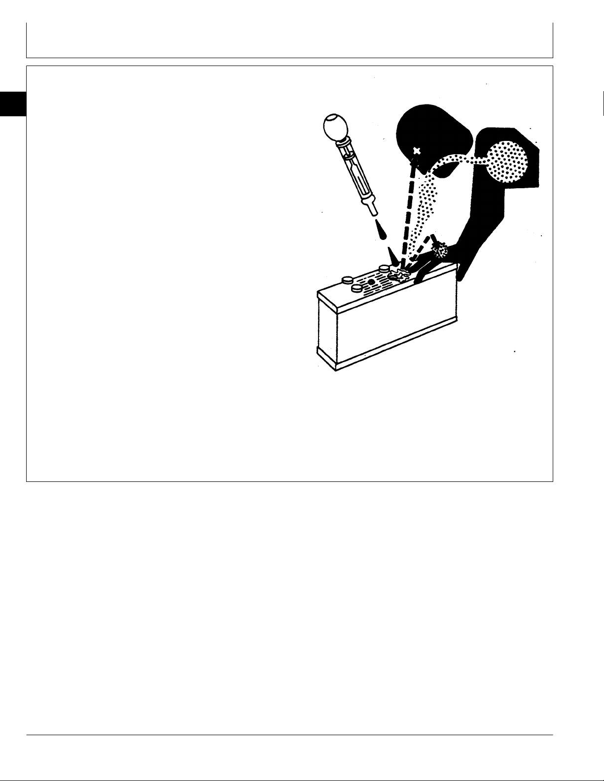
PREVENT ACID BURNS
00
Sulfuric acid in battery electrolyte is poisonous. It is
2
strong enough to burn skin, eat holes in clothing, and
cause blindness if splashed into eyes.
Avoid the hazard by:
1. Filling batteries in a well-ventilated area.
2. Wearing eye protection and rubber gloves.
3. Avoiding breathing fumes when electrolyte is added.
4. Avoiding spilling or dripping electrolyte.
5. Use proper jump start procedure.
If you spill acid on yourself:
1. Flush your skin with water.
2. Apply baking soda or lime to help neutralize the acid.
3. Flush your eyes with water for 15—30 minutes. Get
medical attention immediately.
If acid is swallowed:
1. Do not induce vomiting.
2. Drink large amounts of water or milk, but do not
exceed 2 L (2 quarts).
3. Get medical attention immediately.
Safety/Safety
DX,POISON -19-21APR93
TS203 -UN-23AUG88
CTM42 (24MAR95) 00-2 6076 Diesel Engines—S.N. (500000— )
160101
PN=7
Page 15
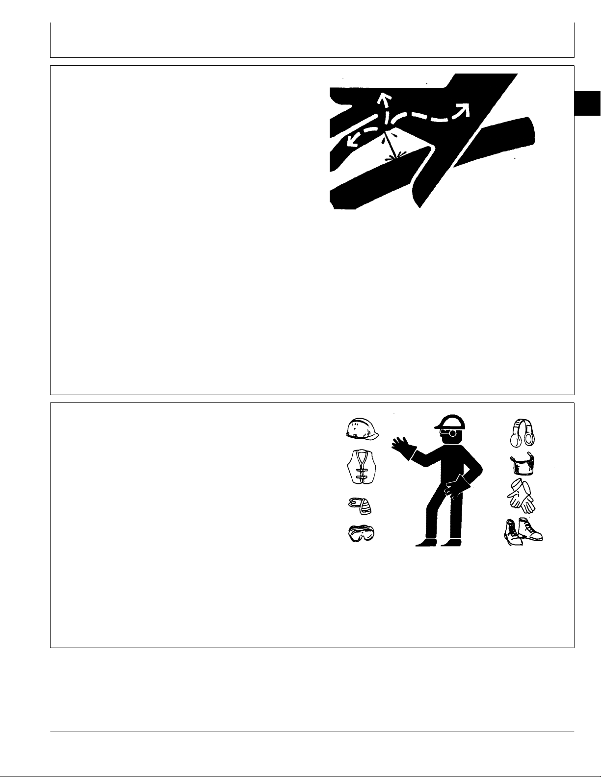
AVOID HIGH-PRESSURE FLUIDS
Safety/Safety
Escaping fluid under pressure can penetrate the skin
causing serious injury.
Avoid the hazard by relieving pressure before
disconnecting hydraulic or other lines. Tighten all
connections before applying pressure.
Search for leaks with a piece of cardboard. Protect
hands and body from high pressure fluids.
If an accident occurs, see a doctor immediately. Any
fluid injected into the skin must be surgically removed
within a few hours or gangrene may result. Doctors
unfamiliar with this type of injury should reference a
knowledgeable medical source. Such information is
available from Deere & Company Medical Department in
Moline, Illinois, U.S.A.
00
3
X9811 -UN-23AUG88
WEAR PROTECTIVE CLOTHING
Wear close fitting clothing and safety equipment
appropriate to the job.
Prolonged exposure to loud noise can cause impairment
or loss of hearing.
Wear a suitable hearing protective device such as
earmuffs or earplugs to protect against objectionable or
uncomfortable loud noises.
Operating equipment safely requires the full attention of
the operator. Do not wear radio or music headphones
while operating machine.
DX,FLUID -19-03MAR93
TS206 -UN-23AUG88
DX,WEAR -19-10SEP90
CTM42 (24MAR95) 00-3 6076 Diesel Engines—S.N. (500000— )
160101
PN=8
Page 16

SERVICE MACHINES SAFELY
00
Tie long hair behind your head. Do not wear a necktie,
4
scarf, loose clothing, or necklace when you work near
machine tools or moving parts. If these items were to get
caught, severe injury could result.
Remove rings and other jewelry to prevent electrical
shorts and entanglement in moving parts.
WORK IN VENTILATED AREA
Engine exhaust fumes can cause sickness or death. If it
is necessary to run an engine in an enclosed area,
remove the exhaust fumes from the area with an
exhaust pipe extension.
If you do not have an exhaust pipe extension, open the
doors and get outside air into the area.
Safety/Safety
TS228 -UN-23AUG88
DX,LOOSE -19-04JUN90
WORK IN CLEAN AREA
Before starting a job:
• Clean work area and machine.
• Make sure you have all necessary tools to do your job.
• Have the right parts on hand.
• Read all instructions thoroughly; do not attempt
shortcuts.
TS220 -UN-23AUG88
DX,AIR -19-04JUN90
T6642EJ -UN-18OCT88
DX,CLEAN -19-04JUN90
CTM42 (24MAR95) 00-4 6076 Diesel Engines—S.N. (500000— )
160101
PN=9
Page 17
Safety/Safety
REMOVE PAINT BEFORE WELDING OR
HEATING
Avoid potentially toxic fumes and dust.
Hazardous fumes can be generated when paint is
heated by welding, soldering, or using a torch.
Do all work outside or in a well ventilated area. Dispose
of paint and solvent properly.
00
5
Remove paint before welding or heating:
• If you sand or grind paint, avoid breathing the dust.
Wear an approved respirator.
• If you use solvent or paint stripper, remove stripper
with soap and water before welding. Remove solvent or
paint stripper containers and other flammable material
from area. Allow fumes to disperse at least 15 minutes
before welding or heating.
AVOID HEATING NEAR PRESSURIZED
FLUID LINES
Flammable spray can be generated by heating near
pressurized fluid lines, resulting in severe burns to
yourself and bystanders. Do not heat by welding,
soldering, or using a torch near pressurized fluid lines or
other flammable materials. Pressurized lines can be
accidentally cut when heat goes beyond the immediate
flame area.
TS220 -UN-23AUG88
DX,PAINT -19-03MAR93
DX,TORCH -19-03MAR93
ILLUMINATE WORK AREA SAFELY
Illuminate your work area adequately but safely. Use a
portable safety light for working inside or under the
machine. Make sure the bulb is enclosed by a wire
cage. The hot filament of an accidentally broken bulb
can ignite spilled fuel or oil.
DX,LIGHT -19-04JUN90
CTM42 (24MAR95) 00-5 6076 Diesel Engines—S.N. (500000— )
160101
PN=10
TS953 -UN-15MAY90
TS223 -UN-23AUG88
Page 18
USE PROPER LIFTING EQUIPMENT
00
Lifting heavy components incorrectly can cause severe
6
injury or machine damage.
Follow recommended procedure for removal and
installation of components in the manual.
PRACTICE SAFE MAINTENANCE
Understand service procedure before doing work. Keep
area clean and dry.
Never lubricate, service, or adjust machine while it is
moving. Keep hands, feet , and clothing from
power-driven parts. Disengage all power and operate
controls to relieve pressure. Lower equipment to the
ground. Stop the engine. Remove the key. Allow
machine to cool.
Safety/Safety
TS226 -UN-23AUG88
DX,LIFT -19-04JUN90
Securely support any machine elements that must be
raised for service work.
Keep all parts in good condition and properly installed.
Fix damage immediately. Replace worn or broken parts.
Remove any buildup of grease, oil, or debris.
Disconnect battery ground cable (-) before making
adjustments on electrical systems or welding on
machine.
DX,SERV -19-03MAR93
TS218 -UN-23AUG88
CTM42 (24MAR95) 00-6 6076 Diesel Engines—S.N. (500000— )
160101
PN=11
Page 19
USE PROPER TOOLS
Safety/Safety
Use tools appropriate to the work. Makeshift tools and
procedures can create safety hazards.
Use power tools only to loosen threaded parts and
fasteners.
For loosening and tightening hardware, use the correct
size tools. DO NOT use U.S. measurement tools on
metric fasteners. Avoid bodily injury caused by slipping
wrenches.
Use only service parts meeting John Deere
specifications.
DISPOSE OF WASTE PROPERLY
Improperly disposing of waste can threaten the
environment and ecology. Potentially harmful waste used
with John Deere equipment include such items as oil,
fuel, coolant, brake fluid, filters, and batteries.
00
7
TS779 -UN-08NOV89
DX,REPAIR -19-04JUN90
Use leakproof containers when draining fluids. Do not
use food or beverage containers that may mislead
someone into drinking from them.
Do not pour waste onto the ground, down a drain, or
into any water source.
Air conditioning refrigerants escaping into the air can
damage the Earth’s atmosphere. Government regulations
may require a certified air conditioning service center to
recover and recycle used air conditioning refrigerants.
Inquire on the proper way to recycle or dispose of waste
from your local environmental or recycling center, or from
your John Deere dealer.
TS1133 -UN-26NOV90
DX,DRAIN -19-03MAR93
CTM42 (24MAR95) 00-7 6076 Diesel Engines—S.N. (500000— )
160101
PN=12
Page 20

LIVE WITH SAFETY
00
Before returning machine to customer, make sure
8
machine is functioning properly, especially the safety
systems. Install all guards and shields.
Safety/Safety
TS231 -19-07OCT88
DX,LIVE -19-25SEP92
CTM42 (24MAR95) 00-8 6076 Diesel Engines—S.N. (500000— )
160101
PN=13
Page 21
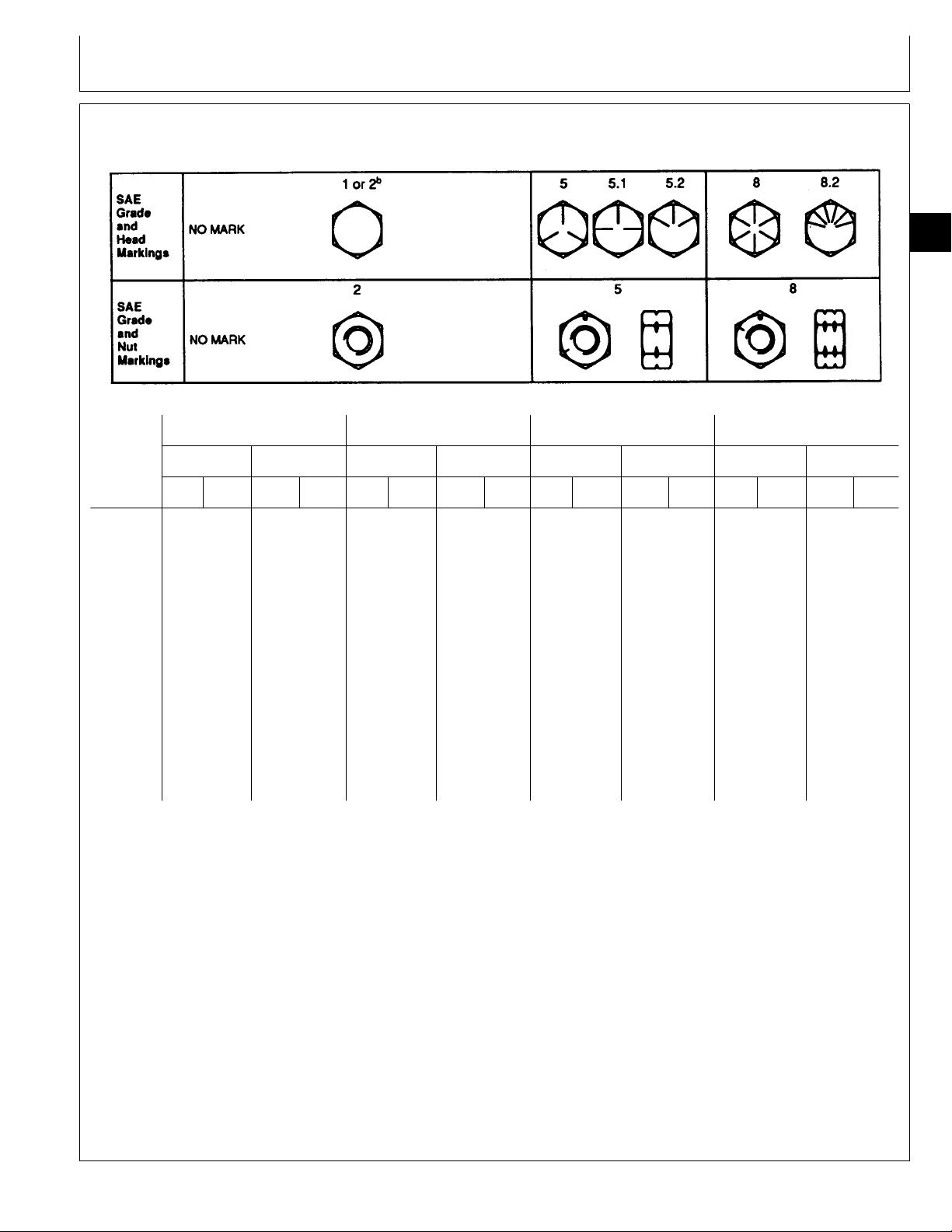
UNIFIED INCH BOLT AND CAP SCREW TORQUE VALUES
Group 01
General Information
01
1
TS1162 -19-04MAR91
Grade 1 Grade 2
Size Lubricated
N·m lb-ft N·m lb-ft N·m lb-ft N·m lb-ft N·m lb-ft N·m lb-ft N·m lb-ft N·m lb-ft
1/4 3.7 2.8 4.7 3.5 6 4.5 7.5 5.5 9.5 7 12 9 13.5 10 17 12.5
5/16 7.7 5.5 10 7 12 9 15 11 20 15 25 18 28 21 35 26
3/8 14 10 17 13 22 16 27 20 35 26 44 33 50 36 63 46
7/16 22 16 28 20 35 26 44 32 55 41 70 52 80 58 100 75
1/2 33 25 42 31 53 39 67 50 85 63 110 80 120 90 150 115
9/16 48 36 60 45 75 56 95 70 125 90 155 115 175 130 225 160
5/8 67 50 85 62 105 78 135 100 170 125 215 160 240 175 300 225
3/4 120 87 150 110 190 140 240 175 300 225 375 280 425 310 550 400
7/8 190 140 240 175 190 140 240 175 490 360 625 450 700 500 875 650
1 290 210 360 270 290 210 360 270 725 540 925 675 1050 750 1300 975
1-1/8 400 300 510 375 400 300 510 375 900 675 1150 850 1450 1075 1850 1350
1-1/4 570 425 725 530 570 425 725 530 1300 950 1650 1200 2050 1500 2600 1950
1-3/8 750 550 950 700 750 550 950 700 1700 1250 2150 1550 2700 2000 3400 2550
1-1/2 1000 725 1250 925 990 725 1250 930 2250 1650 2850 2100 3600 2650 4550 3350
a
Dry
a
Lubricated
DO NOT use these values if a different torque value
or tightening procedure is given for a specific
application. Torque values listed are for general use
only. Check tightness of fasteners periodically.
b
a
Dry
a
Grade 5, 5.1, or 5.2 Grade 8 or 8.2
Lubricated
a
Dry
a
Lubricated
a
Fasteners should be replaced with the same or
higher grade. If higher grade fasteners are used,
these should only be tightened to the strength of the
original.
Dry
a
Shear bolts are designed to fail under predetermined
loads. Always replace shear bolts with identical grade.
Make sure fasteners threads are clean and that you
properly start thread engagement. This will prevent
them from failing when tightening.
Tighten plastic insert or crimped steel-type lock nuts
to approximately 50 percent of the dry torque shown
in the chart, applied to the nut, not to the bolt head.
a
“Lubricated” means coated with a lubricant such as engine oil, or
fasteners with phosphate and oil coatings. “Dry” means plain or zinc
plated without any lubrication.
b
Grade 2 applies for hex cap screws (not hex bolts) up to 152 mm
(6-in.) long. Grade 1 applies for hex cap screws over 152 mm (6-in.)
long, and for all other types of bolts and screws of any length.
Tighten toothed or serrated-type lock nuts to the full
torque value.
DX,TORQ1 -19-20JUL94
CTM42 (24MAR95) 01-1 6076 Diesel Engines—S.N. (500000— )
160101
PN=14
Page 22

General Information/Metric Bolt and Cap Screw Torque Values
METRIC BOLT AND CAP SCREW TORQUE VALUES
01
2
Class 4.8 Class 8.8 or 9.8 Class 10.9 Class 12.9
TS1163 -19-04MAR91
Size Lubricated
N·m lb-ft N·m lb-ft N·m lb-ft N·m lb-ft N·m lb-ft N·m lb-ft N·m lb-ft N·m lb-ft
M6 4.8 3.5 6 4.5 9 6.5 11 8.5 13 9.5 17 12 15 11.5 19 14.5
M8 12 8.5 15 11 22 16 28 20 32 24 40 30 37 28 47 35
M10 23172921433255406347806075559570
M12 40 29 50 37 75 55 95 70 110 80 140 105 130 95 165 120
M14 63 47 80 60 120 88 150 110 175 130 225 165 205 150 260 190
M16 100 73 125 92 190 140 240 175 275 200 350 255 320 240 400 300
M18 135 100 175 125 260 195 330 250 375 275 475 350 440 325 560 410
M20 190 140 240 180 375 275 475 350 530 400 675 500 625 460 800 580
M22 260 190 330 250 510 375 650 475 725 540 925 675 850 625 1075 800
M24 330 250 425 310 650 475 825 600 925 675 1150 850 1075 800 1350 1000
M27 490 360 625 450 950 700 1200 875 1350 1000 1700 1250 1600 1150 2000 1500
M30 675 490 850 625 1300 950 1650 1200 1850 1350 2300 1700 2150 1600 2700 2000
M33 900 675 1150 850 1750 1300 2200 1650 2500 1850 3150 2350 2900 2150 3700 2750
M36 1150 850 1450 1075 2250 1650 2850 2100 3200 2350 4050 3000 3750 2750 4750 3500
a
DO NOT use these values if a different torque value
or tightening procedure is given for a specific
application. Torque values listed are for general use
Dry
a
Lubricated
a
Dry
a
Lubricated
a
Dry
a
Lubricated
a
Dry
a
Make sure fasteners threads are clean and that you
properly start thread engagement. This will prevent
them from failing when tightening.
only. Check tightness of fasteners periodically.
Tighten plastic insert or crimped steel-type lock nuts
Shear bolts are designed to fail under predetermined
loads. Always replace shear bolts with identical
property class.
to approximately 50 percent of the dry torque shown
in the chart, applied to the nut, not to the bolt head.
Tighten toothed or serrated-type lock nuts to the full
torque value.
Fasteners should be replaced with the same or
higher property class. If higher property class
fasteners are used, these should only be tightened to
the strength of the original.
a
“Lubricated” means coated with a lubricant such as engine oil, or
fasteners with phosphate and oil coatings. “Dry” means plain or zinc
plated without any lubrication.
DX,TORQ2 -19-20JUL94
CTM42 (24MAR95) 01-2 6076 Diesel Engines—S.N. (500000— )
160101
PN=15
Page 23

General Information/Engine Model Designation
ENGINE MODEL DESIGNATION
JOHN DEERE ENGINE MODEL—6076
John Deere engine model designation includes number
of cylinders, displacement in liters, aspiration, user code,
and application code. For example:
6076HH030 Engine
6 . . . . . . . . . . . . . . . . . . . . . . . . . . . . . . . . . Number of cylinders
076 . . . . . . . . . . . . . . . . . . . . . . . . . . . . . . . . Liter displacement
H . . . . . . . . . . . . . . . . . . . . . . . . . . . . . . . . Aspiration code
H . . . . . . . . . . . . . . . . . . . . . . . . . . . . . . . . End user code
030 . . . . . . . . . . . . . . . . . . . . . . . . . . Application code
Aspiration Code
A . . . . . . . . . . . . . . . . . Turbocharged and air-to-coolant aftercooled
H . . . . . . . . . . . . . . . . . . . . Turbocharged and air-to-air aftercooled
T . . . . . . . . . . . . . . . . . . . . . . . . . . . . . . . . . . . . . Turbocharged
End User Code
01
3
DW . . . . . . . . . . . . . . . . . . . . . . . . . . . . . . . . . . . . . . . Davenport
F . . . . . . . . . . . . . . . . . . . . . . . . . . . . . . . . . . . . . . . . . . . OEM
H . . . . . . . . . . . . . . . . . . . . . . . . . . . . . . . . . . . . . . . . Harvester
N . . . . . . . . . . . . . . . . . . . . . . . . . . . . . . . . . . . . . . Des Moines
RW . . . . . . . . . . . . . . . . . . . . . . . . . . . . . . . . . . . . . . . . . Tractor
T . . . . . . . . . . . . . . . . . . . . . . . . . . . . . . . . . . . . . . . . Dubuque
Z . . . . . . . . . . . . . . . . . . . . . . . . . . . . . . . . . . . . . . Zweibrucken
Application Code
30, 31, etc.
RG,CTM42,G1,1 -19-14FEB95
CTM42 (24MAR95) 01-3 6076 Diesel Engines—S.N. (500000— )
160101
PN=16
Page 24
General Information/Engine Serial Number Plate Information
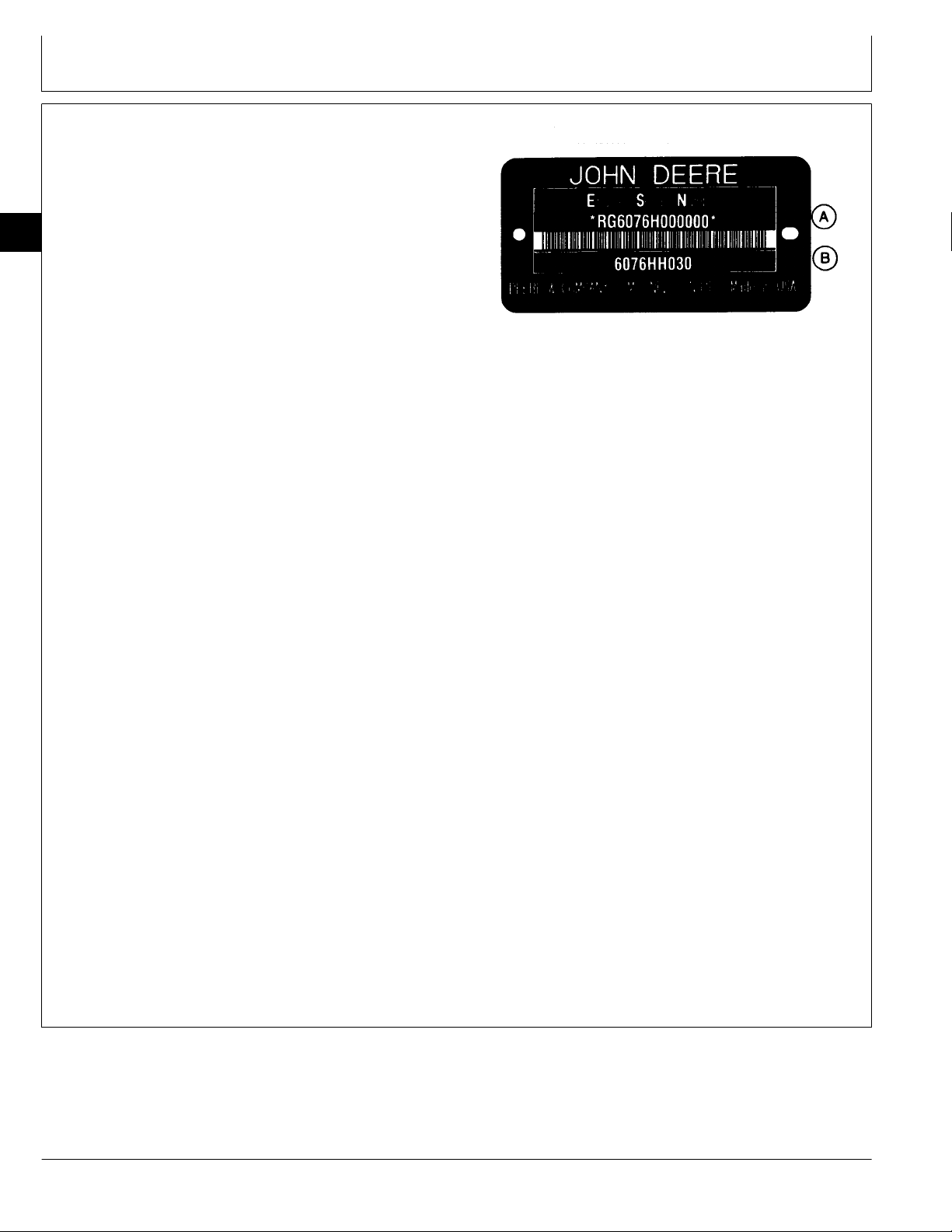
ENGINE SERIAL NUMBER PLATE
INFORMATION
IMPORTANT: The engine serial number plate can be
easily destroyed. Remove the plate or
01
4
• Engine Serial Number (A)
Each engine has a 13-digit John Deere engine serial
number identifying the producing factory, engine model
designation, and a 6-digit sequential number. The
following is an example:
RG6076H000000
RG . . . . . . . . . . . . . . Factory code producing engine
6076H . . . . . . . . . . Engine Model Designation
000000 . . . . . Sequential Number
Factory Code Producing Engine
record the information elsewhere,
before “hot tank” cleaning the block.
RG5804 -UN-12AUG91
RG . . . . . . . . Waterloo Engine Works
Engine Model Designation
6076H . . . . . . Definition explained previously. (See
ENGINE MODEL DESIGNATION.)
Sequential Number
000000 . . . . . 6-digit sequential number.
The engine serial number plate is located either on the
right-hand side of engine between the oil conditioning
housing and fuel injection pump (viewed from flywheel
end) or on the left-hand side of the block directly above
the starting motor.
• Engine Application Data (B)
The second line of information on the engine serial
number plate identifies the engine/Deere machine or
OEM relationship. See ENGINE APPLICATION CHART
later in this group.
RG,CTM42,G1,2 -19-14FEB95
CTM42 (24MAR95) 01-4 6076 Diesel Engines—S.N. (500000— )
160101
PN=17
Page 25

General Information/Engine Application Chart
ENGINE APPLICATION CHART
John Deere Agricultural Equipment Applications
Machine Model No. Engine Model
COMBINES—HARVESTER WORKS
CTS Rice Combine* . . . . . . . . . . . . . . . . . . . . . . . 6076HH030
2056 . . . . . . . . . . . . . . . . . . . . . . . . . . . . . . . . . 6076AZ031
2058 . . . . . . . . . . . . . . . . . . . . . . . . . . . . . . . . . 6076AZ030
2064 . . . . . . . . . . . . . . . . . . . . . . . . . . . . . . . . . 6076AZ030
2066 . . . . . . . . . . . . . . . . . . . . . . . . . . . . . . . . . 6076HZ031
9500* . . . . . . . . . . . . . . . . . . . . . . . . . . . . . . . . 6076HH031, 6076HH032
9600* . . . . . . . . . . . . . . . . . . . . . . . . . . . . . . . . 6076HH030, 6076HH031
COMBINES—ZWEIBRUCKEN
2056 Hillmaster . . . . . . . . . . . . . . . . . . . . . . . . . . 6076AZ031
2058 Hillmaster . . . . . . . . . . . . . . . . . . . . . . . . . . 6076AZ030
2064 Hillmaster . . . . . . . . . . . . . . . . . . . . . . . . . . 6076AZ030
2066 Hillmaster . . . . . . . . . . . . . . . . . . . . . . . . . . 6076HZ031
FORAGE HARVESTERS—ZWEIBRUCKEN
6610 . . . . . . . . . . . . . . . . . . . . . . . . . . . . . . . . . 6076HZ030
01
5
COTTON PICKER—DES MOINES
9960** . . . . . . . . . . . . . . . . . . . . . . . . . . . . . . . . 6076AN030
9965 . . . . . . . . . . . . . . . . . . . . . . . . . . . . . . . . . 6067AN031
TRACTORS—WATERLOO
7700 . . . . . . . . . . . . . . . . . . . . . . . . . . . . . . . . . 6076TRW31
7800 . . . . . . . . . . . . . . . . . . . . . . . . . . . . . . . . . 6076TRW30
8100 . . . . . . . . . . . . . . . . . . . . . . . . . . . . . . . . . 6076HRW33
8200 . . . . . . . . . . . . . . . . . . . . . . . . . . . . . . . . . 6076HRW34
8300 . . . . . . . . . . . . . . . . . . . . . . . . . . . . . . . . . 6076HRW35
8560 4-Wheel Drive*** . . . . . . . . . . . . . . . . . . . . . 6076HRW30
8570 4-Wheel Drive . . . . . . . . . . . . . . . . . . . . . . . 6076HRW32
* Beginning with combine serial number (645000— )
** Above P.I.N. 4001
*** Beginning with tractor serial number (5000— )
RG,CTM42,G1,3 -19-16AUG94
CTM42 (24MAR95) 01-5 6076 Diesel Engines—S.N. (500000— )
160101
PN=18
Page 26

General Information/Engine Application Chart
ENGINE APPLICATION CHART—CONTINUED
John Deere Industrial Equipment Applications
Machine Model No. Engine Model
01
LOADERS—DUBUQUE
6
644G . . . . . . . . . . . . . . . . . . . . . . . . . . . . . . . . . 6076ADW30
644GH . . . . . . . . . . . . . . . . . . . . . . . . . . . . . . . . 6076ADW32
644G Dual Power . . . . . . . . . . . . . . . . . . . . . . . . 6076ADW33
MOTOR GRADERS—DUBUQUE
770B . . . . . . . . . . . . . . . . . . . . . . . . . . . . . . . . . 6076TDW30
770BH . . . . . . . . . . . . . . . . . . . . . . . . . . . . . . . . 6076ADW31
772BH . . . . . . . . . . . . . . . . . . . . . . . . . . . . . . . . 6076ADW31
EXCAVATORS—DUBUQUE
892E . . . . . . . . . . . . . . . . . . . . . . . . . . . . . . . . . 6076AT030
BULLDOZERS—DUBUQUE
850C . . . . . . . . . . . . . . . . . . . . . . . . . . . . . . . . . 6076AT032
OEM APPLICATIONS
Machine Model No. Engine Model
Marine . . . . . . . . . . . . . . . . . . . . . . . . . . . . . . . 6076AFM030
OEM Repower . . . . . . . . . . . . . . . . . . . . . . . . . . 6076AF030
6076HF030
6076TF030
RG,CTM42,G1,3B -19-16AUG94
RG,CTM42,G1,3A -19-16AUG94
CTM42 (24MAR95) 01-6 6076 Diesel Engines—S.N. (500000— )
160101
PN=19
Page 27

DIESEL FUEL
Group 02
Fuels, Lubricants, and Coolant
Consult your local fuel distributor for properties of the
diesel fuel available in your area.
In general, diesel fuels are blended to satisfy the low
temperature requirements of the geographical area in
which they are marketed.
Diesel fuels specified to EN 590 or ASTM D975 are
recommended.
In all cases, the fuel must meet the following
properties:
• Cetane Number 40 minimum. Cetane number
greater than 50 is preferred, especially for
temperatures below -20˚ C (-4˚ F) or elevations
above 1500 m (5000 ft).
• Cold Filter Plugging Point (CFPP) below the
expected low temperature OR Cloud Point at least
5˚ C (9˚ F) below the expected low temperature.
• Sulfur Content
— Sulfur content should not exceed 0.5%. Sulfur
content less than 0.05% is preferred.
— If diesel fuel with sulfur content greater than 0.5%
is used, reduce the service interval for engine oil and
filter changes by 50%.
— DO NOT use diesel fuel with sulfur content greater
than 1.0%.
Bio-diesel fuels meeting DIN 51606 or equivalent
specification may be used.
RG,FUEL1 -19-22FEB95
02
1
LUBRICITY OF DIESEL FUELS
Diesel fuel must have adequate lubricity to ensure
proper operation and durability of fuel injection system
components.
Diesel fuels for highway use in the United States now
require sulfur content less than 0.05%. Diesel fuel in
the European Union will require sulfur content less
than 0.05% by 1 October 1996.
Experience shows that some low sulfur diesel fuels
may have inadequate lubricity and their use may
reduce performance in fuel injection systems due to
inadequate lubrication of injector components. The
lower concentration of aromatic compounds in these
fuels also adversely affects injection pump seals and
may result in leaks.
Use of low lubricity diesel fuels may also cause
accelerated wear, injection nozzle erosion or
corrosion, engine speed instability, hard starting, low
power, and engine smoke.
Fuel lubricity should pass a minimum of 3300 gram
load level as measured by the BOCLE scuffing test.
ASTM D975 and EN 590 specifications do not require
fuels to pass a fuel lubricity test. Diesel fuels meeting
U.S. Military Specification VV—F—800E pass a fuel
lubricity test.
If fuel of low or unknown lubricity is used, add John
Deere ALL-SEASON DIESEL FUEL CONDITIONER
or equivalent at the specified concentration.
RG,FUEL5 -19-22FEB95
CTM42 (24MAR95) 02-1 6076 Diesel Engines—S.N. (500000— )
160101
PN=20
Page 28

ENGINE BREAK-IN OIL
Fuels, Lubricants, and Coolant/Engine Break-In Oil
New engines are filled at the factory with John Deere
ENGINE BREAK-IN OIL. During the break-in period,
add John Deere ENGINE BREAK-IN OIL as needed
to maintain the specified oil level.
Change the oil and filter after the first 100 hours of
operation of a new or rebuilt engine.
02
2
After engine overhaul, fill the engine with John Deere
ENGINE BREAK-IN OIL.
If John Deere ENGINE BREAK-IN OIL is not
available, use a diesel engine oil meeting one of the
following during the first 100 hours of operation:
• API Service Classification CE
• CCMC Specification D4
After the break-in period, use John Deere PLUS-50
or other diesel engine oil as recommended in this
manual.
IMPORTANT: Do not use John Deere PLUS-50 oil
or engine oils meeting API CG4,
API CF4, or CCMC D5 performance
levels during the first 100 hours of
operation of a new or rebuilt engine.
These oils will not allow the engine
to break-in properly.
®
DX,ENOIL4 -19-17OCT94
CTM42 (24MAR95) 02-2 6076 Diesel Engines—S.N. (500000— )
160101
PN=21
Page 29
Fuels, Lubricants, and Coolant/Engine Oil
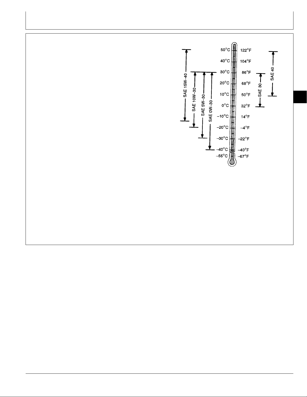
DIESEL ENGINE OIL
Use oil viscosity based on the expected air temperature
range during the period between oil changes.
The following oil is preferred.
• John Deere PLUS-50
®
If John Deere PLUS-50 engine oil and a John Deere oil
filter are used, the service interval for oil and filter
changes may be extended by 50 hours.
The following oil is also recommended:
• John Deere TORQ-GARD SUPREME
®
Other oils may be used if they meet one or more of the
following:
• John Deere UNI-GARD™
• API Service Classification CG-4
• API Service Classification CF-4
• API Service Classification CE
• CCMC Specification D5 and Mercedes Benz MB228.3
• CCMC Specification D4 and Mercedes Benz MB228.1
Viscosity grade SAE 15W-40 is preferred.
If diesel fuel with sulfur content greater than 0.5% is
used, reduce the service interval by 50%.
02
3
TS1619 -UN-12SEP94
DX,ENOIL -19-16SEP94
CTM42 (24MAR95) 02-3 6076 Diesel Engines—S.N. (500000— )
160101
PN=22
Page 30
Fuels, Lubricants, and Coolant/Grease
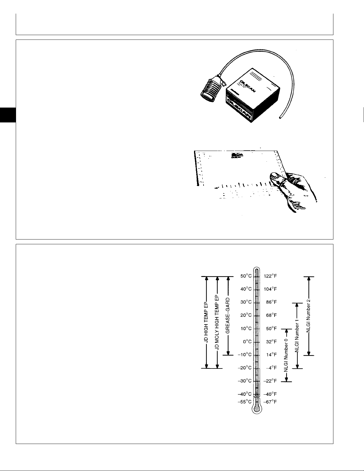
OILSCAN® AND COOLSCAN™
OILSCAN and COOLSCAN are John Deere sampling
programs to help you monitor machine performance and
identify potential problems before they cause serious
damage.
Oil and coolant samples should be taken from each
system prior to its recommended change interval.
02
4
Check with your John Deere dealer for the availability of
OILSCAN and COOLSCAN kits.
T6828AB -UN-15JUN89T6829AB -UN-18OCT88
GREASE
Use grease based on the expected air temperature
range during the service interval.
The following greases are preferred:
• John Deere MOLY HIGH TEMPERATURE EP
GREASE
• John Deere HIGH TEMPERATURE EP GREASE
• John Deere GREASE-GARD™
Other greases may be used if they meet one of the
following:
• SAE Multipurpose EP Grease with a maximum of
5% molybdenum disulfide
• SAE Multipurpose EP Grease
Greases meeting Military Specification MIL-G-10924F
may be used as arctic grease.
DX,OILSCAN -19-16APR92
DX,GREA1 -19-02NOV94
CTM42 (24MAR95) 02-4 6076 Diesel Engines—S.N. (500000— )
160101
PN=23
TS1622 -UN-02NOV94
Page 31

Fuels, Lubricants, and Coolant/Engine Coolant Requirements
ALTERNATIVE AND SYNTHETIC LUBRICANTS
Conditions in certain geographical areas may require
lubricant recommendations different from those
printed in this manual. Some John Deere lubricants
may not be available in your location. Consult your
John Deere dealer to obtain information and
recommendations.
ENGINE COOLANT REQUIREMENTS
Synthetic lubricants may be used if they meet the
performance requirements listed in this manual.
02
5
DX,ALTER -19-01FEB94
RG6258 -UN-22APR92
A—Quality Water B—Ethylene Glycol Concentrate C—Supplemental Coolant Additives
(Antifreeze) (SCA’s)
Engine Coolant
To meet cooling system protection requirements, the
coolant MUST consist of a 50/50 mixture of quality
water and ethylene glycol concentrate (antifreeze).
Supplemental coolant additives (SCA’s) must be
added to this mixture. Add 3% (by volume) TY16004
or TY16005 Liquid Coolant Conditioner. If an
equivalent product is used, always follow the
IMPORTANT: Supplemental coolant additives
MUST be added to the coolant
solution. Ethylene glycol concentrate
(antifreeze) DOES NOT contain
chemical inhibitors needed to
control liner pitting or erosion, rust,
scale, and acidity.
supplier’s recommendations printed on the container.
See ENGINE COOLANT SPECIFICATIONS, later in
this section, for further definition.
Makeup of the coolant between changes MUST
consist of the same requirements as during a
complete change. Performing a CoolScan analysis is
the recommended method for determining the amount
of quality water, ethylene glycol concentrate, and
supplemental coolant additives that should be added.
RG,COOL1 -19-10OCT94
CTM42 (24MAR95) 02-5 6076 Diesel Engines—S.N. (500000— )
160101
PN=24
Page 32

Fuels, Lubricants, and Coolant/Engine Coolant Requirements
ENGINE COOLANT REQUIREMENTS—CONTINUED
02
6
A—Cylinder Liner Walls B—Engine Coolant C—Vapor Bubbles
Coolant solutions of ethylene glycol concentrate
(antifreeze), quality water, and supplemental coolant
additives (SCA’s) MUST be used year-round to
protect against freezing, boil-over, liner erosion or
pitting, and to provide a stable, non-corrosive
environment for seals, hoses, and metal engine parts.
Water pump impellers and cylinder liner walls (A)
which are in contact with engine coolant (B) can be
eroded or pitted unless the proper concentration and
type of SCA’s are present in the coolant solution.
Vapor bubbles (C) are formed when piston impacts
against liner ID causing walls to vibrate; sending
compression waves into the coolant.
RG6263 -UN-22APR92
Erosion or pitting is caused by the formation and
collapse of tiny vapor bubbles in the coolant on the
surface of metal parts. Over a period of time, this
pitting will progress completely through the metal.
Generally, the most critical erosion occurs in the
cylinder liner area of wet-sleeve, heavy-duty engines.
If coolant is allowed to enter the combustion
chamber, engine failure or other serious damage will
result.
Use of SCA’s will reduce the effects of erosion and
pitting. The chemicals in the additives form a
protective film on cylinder liner surface. This film acts
as a barrier against collapsing vapor bubbles and
also reduces the quantity of bubbles formed.
RG,COOL1A -19-10OCT94
CTM42 (24MAR95) 02-6 6076 Diesel Engines—S.N. (500000— )
160101
PN=25
Page 33

Fuels, Lubricants, and Coolant/Recommended Engine Coolant
RECOMMENDED ENGINE COOLANT
Solutions of antifreeze and supplemental coolant
additives MUST be used year-round for freeze
protection, boil-over protection, and to provide a
stable, non-corrosive environment for seals, hoses
and metal engine parts.
John Deere Prediluted Antifreeze/Summer Coolant is
preferred. John Deere Antifreeze/Summer Coolant
Concentrate and John Deere COOL-GARD™, where
available, are also recommended.
Refer to your vehicle operator’s manual for the
service life of these products.
• JOHN DEERE PREDILUTED
ANTIFREEZE/SUMMER COOLANT
This product contains all the necessary ingredients
that make up the proper coolant solution: chemically
pure water, ethylene glycol (low silicate antifreeze),
and supplemental coolant additives (SCA’s). It is
ready to use; no mixing is required.
John Deere Prediluted Antifreeze/Summer Coolant
permits extended service life.
• JOHN DEERE ANTIFREEZE/SUMMER COOLANT
CONCENTRATE
This product contains ethylene glycol (low silicate
antifreeze) and supplemental coolant additives
(SCA’s). It must be mixed with quality water, as
described later in this section, before adding to the
engine cooling system. The proportion of water to be
used depends upon the lowest freeze protection
temperature desired according to the following table:
% CONCENTRATE FREEZE PROTECTION LIMIT
40 -24˚ C (-12˚ F)
50 -37˚ C (-34˚ F)
60 -52˚ C (-62˚ F)
• JOHN DEERE COOL-GARD™
In certain geographical areas, John Deere
COOL-GARD is marketed for use in the engine
cooling system. This product contains all the
necessary ingredients that make up the proper
coolant solution: chemically pure water, ethylene
glycol (low silicate antifreeze), and supplemental
coolant additives (SCA’s). It is ready to add to cooling
system as is; no mixing or supplemental coolant
additives required. Contact your John Deere Parts
Network for local availability.
02
7
RG,COOL2,CTM -19-23FEB95
CTM42 (24MAR95) 02-7 6076 Diesel Engines—S.N. (500000— )
160101
PN=26
Page 34

Fuels, Lubricants, and Coolant/Engine Coolant Specifications
ENGINE COOLANT SPECIFICATIONS
Contact your authorized servicing dealer or engine
distributor to determine what the cooling system of
this engine is filled with and the winter freeze
protection level.
If John Deere coolant products are not used, other
low silicate ethylene glycol base coolants for
02
heavy-duty diesel engines may be used when mixed
8
with quality water and supplemental coolant additives
(SCA’s), if they meet one of the following
specifications:
• ASTM D5345 (prediluted coolant)
• ASTM D4985 (coolant concentrate) in a 40 to 60%
mixture of concentrate with quality water.
Coolants meeting these specifications require addition
of supplemental coolant additives (SCA’s), formulated
for heavy-duty diesel engines, for protection against
corrosion and cylinder liner erosion and pitting.
Water Quality:
Distilled, de-ionized, or demineralized water is
preferred for use in cooling systems. Mineral
(hard/tap) water should NEVER be put in a cooling
system unless first tested. However, water that meets
the following water quality specifications is
acceptable.
Water Quality Specifications
Parts Grains
Per Per
Item Million Gallon
Chlorides (maximum) . . . . . . . . . . . . . . . . . 40 2.5
Sulfates (maximum) . . . . . . . . . . . . . . . . . . 100 5.9
Total Dissolved Solids (maximum) . . . . . . . . . 340 20
Total Hardness (maximum) . . . . . . . . . . . . . 170 10
pH Level . . . . . . . . . . . . . . . . . . . . . . . . . . . . . . . . . 5.5—9.0
If Chlorides, Sulfates, or Total Dissolved Solids are
higher than the above given specifications, the water
must be distilled, de-mineralized, or de-ionized before
using in cooling system.
If Total Hardness is higher than the above given
specification and all other parameters are within the
given specifications, the water must be softened
before using in cooling system.
Ethylene Glycol Concentrate (Antifreeze):
IMPORTANT: DO NOT use ethylene glycol
concentrate containing sealer or
stop-leak additives.
RG,COOL3 -19-23FEB95
CTM42 (24MAR95) 02-8 6076 Diesel Engines—S.N. (500000— )
160101
PN=27
Page 35

Fuels, Lubricants, and Coolant/Engine Coolant Specifications
ENGINE COOLANT SPECIFICATIONS—CONTINUED
02
9
RG7298 -UN-13FEB95
Supplemental Coolant Additives (SCA’s):
IMPORTANT: DO NOT over-inhibit antifreeze
solutions, as this can cause
silicate-dropout. When this happens,
a gel-type deposit is created which
retards heat transfer and coolant
flow.
NOTE: John Deere Prediluted Antifreeze/Summer
Coolant, John Deere Antifreeze/Summer
Coolant Concentrate, and John Deere
COOL-GARD contain supplemental coolant
additives (SCA’s). However, as the coolant
solution loses its effectiveness, additives will
need to be added.
Inhibit the antifreeze-coolant mix with a non-chromate
inhibitor such as John Deere Liquid Coolant
Conditioner. SCA’s guard against rust, corrosion, and
liner pitting. ALWAYS follow the supplier’s
recommendations printed on the container.
John Deere Liquid Coolant Conditioner is available in
the following sizes:
IMPORTANT: Check inhibitors between drain
intervals. Replenish inhibitors by the
addition of a supplemental coolant
additive as necessary. See your
vehicle operator’s manual for
details.
DO NOT use soluble oil.
Additives eventually lose their effectiveness and must
be recharged with additional liquid coolant conditioner.
See label on container for recommended service
intervals and concentration rates. See
REPLENISHING SUPPLEMENTAL COOLANT
ADDITIVES (SCA’S) BETWEEN COOLANT
CHANGES, later in this group.
Contact your authorized servicing dealer or engine
distributor, if there are further questions.
—TY16004 473 mL (16 oz) container
—TY16005 3.8 L (1 US gal) container
RG,COOL3A,CTM -19-23FEB95
CTM42 (24MAR95) 02-9 6076 Diesel Engines—S.N. (500000— )
160101
PN=28
Page 36

Fuels, Lubricants, and Coolant/Replenish Supplemental Coolant Additives Between Coolant Changes
REPLENISHING SUPPLEMENTAL COOLANT ADDITIVES (SCA’S) BETWEEN COOLANT
CHANGES
02
10
RG6261 -UN-22APR92
Through time and use, original additives eventually
lose their effectiveness and must be recharged with
additional supplemental coolant additives available in
the form of liquid coolant conditioner.
Maintaining the correct coolant conditioner
concentration (SCA’s) and freeze point is essential in
your cooling system to protect against liner pitting,
corrosion, and freeze-ups due to incorrect coolant
solution.
A coolant strip test, available from your dealer,
provides a simple, effective way to check freeze point
and molybdate/nitrite levels. These results can be
compared to the SCA chart to determine the amount
of coolant conditioner in your system.
NOTE: Refer to your vehicle operator’s manual for
specific service intervals for checking and
charging your coolant.
For a more thorough evaluation of your coolant,
perform a CoolScan analysis. If a CoolScan analysis
is not available, recharge system per instructions
printed on label of TY16004 or TY16005 John Deere
Liquid Coolant Conditioner.
RG6262 -UN-22APR92
IMPORTANT: ALWAYS maintain coolant at correct
level and concentration. DO NOT
operate engine without coolant for
even a few minutes.
If frequent coolant make-up is
required, the glycol concentration
should be checked with JT05460
Refractometer to assure that the
desired freeze point is maintained.
Follow manufacturer’s instructions
provided with refractometer.
See ENGINE COOLANT SPECIFICATIONS earlier in
this group for proper mixing of coolant ingredients
before adding to the cooling system.
RG,COOL4,CTM -19-23FEB95
CTM42 (24MAR95) 02-10 6076 Diesel Engines—S.N. (500000— )
160101
PN=29
Page 37

Fuels, Lubricants, and Coolant/Operating in Tropical Conditions
OPERATING IN TROPICAL CONDITIONS
Always use a recommended glycol base engine
coolant, even when operating in geographical areas
where freeze protection is not required.
Only when no glycol base engine coolant (antifreeze)
is available, use distilled, deionized, or demineralized
water meeting the quality specifications on the
previous page. Add to the water an initial charge of
supplemental coolant additives, such as John Deere
Liquid Coolant Conditioner or equivalent. The
recommended concentration of John Deere Liquid
Coolant Conditioner must be doubled to 6% (60 mL
per Liter of cooling system capacity) by volume when
used with water only (no antifreeze). Double other
manufacturer’s recommended concentration.
IMPORTANT: Never use water as the engine
coolant without an initial charge of
supplemental coolant additives.
Using water alone will cause severe
corrosion and pitting damage to
vital engine parts. Drain system and
refill cooling system as specified in
your vehicle operator’s manual.
RG,COOL6,CTM -19-23FEB95
02
11
CTM42 (24MAR95) 02-11 6076 Diesel Engines—S.N. (500000— )
160101
PN=30
Page 38

Fuels, Lubricants, and Coolant/Flush and Service Cooling System
FLUSH AND SERVICE COOLING SYSTEM
02
12
TS281 -UN-23AUG88
CAUTION: Explosive release of fluids from
N
pressurized cooling system can cause
serious burns.
Shut off engine. Only remove filler cap
when cool enough to touch with bare
hands. Slowly loosen cap to first stop to
relieve pressure before removing cap
completely.
IMPORTANT: Air must be expelled from cooling
system when system is refilled.
Follow procedure given in your
operator’s manual.
The ethylene glycol base (antifreeze) can become
depleted of SCA’s allowing various acids to form that
will damage engine components. In addition, heavy
metals, such as lead, copper and zinc, accumulate in
the ethylene glycol base. The heavy metals come
from corrosion that occurs to some degree within a
cooling system. When a coolant is saturated to the
point where it can no longer hold heavy metals and
other dissolved solids, they settle out and act as
abrasives on engine parts.
Flush cooling system and replace thermostats as
described in your operator’s manual. Clean cooling
system with clean water and TY15979 John Deere
Heavy-Duty Cooling System Cleaner or an equivalent
cleaner such as FLEETGUARD® RESTORE™. Follow
the instructions provided with the cleaner. Refill
cooling system with the appropriate coolant solution.
See ENGINE COOLANT SPECIFICATIONS, earlier in
this group.
IMPORTANT: NEVER overfill the system. A
pressurized system needs space for
heat expansion without overflowing
at the top of the radiator. Coolant
level should be at bottom of radiator
filler neck.
After adding new coolant solution, run engine until it
reaches operating temperature. This mixes the
coolant solution uniformly and circulates it through the
entire system. After running engine, check coolant
level and entire cooling system for leaks.
Contact your authorized servicing dealer or engine
distributor, if there are further questions.
NOTE: Refer to your operator’s manual for a specific
service interval.
FLEETGUARD® is a registered trademark of Cummins Engine
Company.
RESTORE™ is a trademark of FLEETGUARD®.
CTM42 (24MAR95) 02-12 6076 Diesel Engines—S.N. (500000— )
RG,COOL,REQ8B -19-17AUG94
160101
PN=31
Page 39

Fuels, Lubricants, and Coolant/Disposing of Coolant
DISPOSING OF COOLANT
Improperly disposing of engine coolant can threaten the
environment and ecology.
Use leakproof containers when draining fluids. Do not
use food or beverage containers that may mislead
someone into drinking from them.
Do not pour waste onto the ground, down a drain, or
into any water source.
Inquire on the proper way to recycle or dispose of waste
from your local environmental or recycling center, or from
your John Deere dealer.
02
13
TS1133 -UN-26NOV90
RG,COOL5 -19-01SEP94
CTM42 (24MAR95) 02-13 6076 Diesel Engines—S.N. (500000— )
160101
PN=32
Page 40

02
14
Fuels, Lubricants, and Coolant/Disposing of Coolant
CTM42 (24MAR95) 02-14 6076 Diesel Engines—S.N. (500000— )
160101
PN=33
Page 41

ENGINE REPAIR STAND
NOTE: Only the 2722 kg (6000 lb) heavy duty engine
repair stand (A) No. D05223ST manufactured by
Owatonna Tool Co., Owatonna, Minnesota is
referenced in this manual. When any other repair
stand is used, consult the manufacturer’s
instructions for mounting the engine.
Group 03
Engine Mounting
03
1
RG4929 -UN-15DEC88
S11,2000,EM -19-08MAR94
CTM42 (24MAR95) 03-1 6076 Diesel Engines—S.N. (500000— )
160101
PN=34
Page 42

Engine Mounting/Install 400 Series Adapters on Repair Stand
SAFETY PRECAUTIONS
• The engine repair stand should be used only by
qualified service technicians familiar with this
equipment.
• To maintain shear strength specifications, alloy steel
SAE Grade 8 or higher cap screws must be used to
mount adapters and engine to repair stand. Use
LOCTITE® 242 Thread Lock and Sealer on cap
screws when installing lifting straps on engine.
Tighten cap screws to 170 N·m (125 lb-ft).
03
• For full thread engagement, be certain that tapped
2
holes in adapters and engine blocks are clean and
not damaged. A thread length engagement equal to
1-1/2 screw diameters minimum is required to
maintain strength requirements.
• To avoid structural or personal injury, do not exceed
the maximum capacity rating of 2722 kg (6000 lb).
Maximum capacity is determined with the center of
the engine located not more than 330 mm (13 in.)
from the mounting hub surface of the engine stand.
• To avoid an unsafe off-balance load condition, the
center of balance of an engine must be located within
51 mm (2 in.) of the engine stand rotating shaft.
Engine center of balance is generally located a few
millimeters above the crankshaft.
• To prevent possible personal injury due to engine
slippage, recheck to make sure engine is solidly
mounted before releasing support from engine lifting
device.
• Never permit any part of the body to be positioned
under a load being lifted or suspended. Accidental
slippage may result in personal injury.
• The lifting jack is to be used when it is necessary to
lift the engine for rotation. When working on the
engine, the jack should be at its lowest position to
keep the center of gravity low and the possibility of
tipping low.
• To prevent possible personal injury due to sudden
engine movement, lower engine by operating jack
release valve slowly. Do not unscrew release valve
knob more than two turns from its closed position.
LOCTITE® is a registered trademark of Loctite Corporation.
S11,2000,DZ -19-21MAR95
INSTALL 400 SERIES ADAPTERS ON
REPAIR STAND
1. Attach the No. 60581 Engine Adapter (A) to mounting
hub of the engine repair stand using SAE Grade 8
socket head screws. Tighten screws to 135 N·m (100
lb-ft).
2. Attach the No. 51400 end adapter (B) to the engine
adapter, using four 5/8-11 x 2 in. SAE Grade 8 cap
screws. Tighten screws to 135 N·m (100 lb-ft).
S11,2000,FB -19-08MAR94
CTM42 (24MAR95) 03-2 6076 Diesel Engines—S.N. (500000— )
160101
PN=35
RG4930 -UN-15DEC88
Page 43

Engine Mounting/Engine Lifting Procedure
ENGINE LIFTING PROCEDURE
03
3
CAUTION: Use of JDG23 Engine Lifting
N
Sling (A) is the ONLY APPROVED method
for lifting engine. Use extreme caution when
lifting and NEVER permit any part of the
body to be positioned under an engine
being lifted or suspended.
1. Attach the JDG23 Engine Lifting Sling to engine
lifting straps (B) and overhead hoist or floor crane.
IMPORTANT: Ensure that engine lifting straps are
secured to engine with SAE Grade 8
(or higher) cap screws. Apply
LOCTITE 242 Thread Lock and
Sealer and tighten cap screws to
170 N·m (125 lb-ft).
RG5788 -UN-09AUG91
NOTE: If engine does not have lifting straps, they can
be procured through service parts network.
USE ONLY lifting straps supplied by DEERE.
2. Carefully lift engine and slowly lower to desired
location.
RG,CTM42,G3,1 -19-23MAR95
CTM42 (24MAR95) 03-3 6076 Diesel Engines—S.N. (500000— )
160101
PN=36
Page 44

Engine Mounting/Disconnect Turbocharger Oil Inlet Line
CLEAN ENGINE
1. Cap or plug all openings on engine. If electrical
components (starter, alternator, etc.) are not removed
prior to cleaning, cover with plastic and tape securely to
prevent moisture from entering.
2. Steam-clean engine thoroughly.
IMPORTANT: Never steam clean or pour cold water
on an injection pump while it is still
warm. To do so may cause seizure of
03
pump parts.
4
S11,2000,EC -19-20AUG92
DISCONNECT TURBOCHARGER OIL INLET
LINE
1. Drain all engine oil and coolant, if not previously done.
IMPORTANT: When servicing 6076 Engines on a
rollover stand, disconnect turbocharger
oil inlet line (A) from oil conditioning
housing or turbocharger before rolling
engine over. Failure to do so may
cause a hydraulic lock upon starting
engine. Hydraulic lock may cause
possible engine failure.
Hydraulic lock occurs when trapped oil
in the oil filter housing drains through
the turbocharger, the exhaust and
intake manifolds, and then into the
cylinder head.
After starting the engine, the trapped
oil in the manifold and head is released
into the cylinder(s) filling them with oil
causing hydraulic lock and possible
engine failure.
RG5323 -UN-06DEC88
2. Disconnect turbocharger oil inlet line at turbocharger
or oil conditioning housing.
RG,CTM42,G03,3 -19-24SEP91
CTM42 (24MAR95) 03-4 6076 Diesel Engines—S.N. (500000— )
160101
PN=37
Page 45

Engine Mounting/Mount Engine On Repair Stand
MOUNT ENGINE ON REPAIR STAND
03
5
RG5965 -UN-05SEP91
NOTE: If starting motor is to be removed from
engine, remove before mounting engine onto
repair stand.
CAUTION: Never remove the overhead
N
lifting equipment from the equipment until
the engine is securely mounted to the stand
and all mounting hardware is tightened to
specified values. Always release the
overhead lifting equipment slowly.
1. Mount the starter side of the engine to the engine
adapter with four 5/8-11UNC Flanged-head, SAE
Grade 8 or higher grade cap screws (A).
2. Tighten cap screws to 203 N·m (150 lb-ft).
3. Carefully remove lift sling from engine.
RG,CTM42,G3,2 -19-21MAR95
CTM42 (24MAR95) 03-5 6076 Diesel Engines—S.N. (500000— )
160101
PN=38
Page 46

03
6
Engine Mounting/Mount Engine On Repair Stand
CTM42 (24MAR95) 03-6 6076 Diesel Engines—S.N. (500000— )
160101
PN=39
Page 47

6076 ENGINE DISASSEMBLY SEQUENCE
Group 04
Engine Rebuild Guide
The following sequence is suggested when complete
disassembly for overhaul is required. Refer to the
appropriate repair group when removing individual
engine components.
NOTE: Remove starting motor before mounting
engine into repair stand.
1. Drain all coolant and engine oil. Check engine oil
for metal contaminates.
2. Remove turbocharger oil inlet line.
3. Remove breather hose.
4. Remove fan pulley and water manifold assembly.
5. Remove turbocharger exhaust elbow and
connector. Remove turbocharger.
NOTE: DO NOT damage option code label (if
equipped), when removing rocker arm cover.
6. Remove rocker arm cover.
7. Remove rocker arm assembly and push rods.
Identify parts for re-assembly.
8. Remove alternator and mounting brackets.
9. Remove front crankshaft pulley and damper
assembly.
10. Remove fuel injection lines and injection nozzles.
11. Remove water pump.
12. Remove engine oil filter and oil conditioning
housing.
13. Remove injection pump gear cover and remove
injection pump. Remove fuel filter and mounting base.
14. On 6076A Engines, remove aftercooler cover and
aftercooler assembly.
15. Remove exhaust manifold and air intake manifold.
16. Remove turbocharger oil return line.
17. Remove cylinder head with valve assembly.
Remove head gasket.
18. On SAE No. 3 flywheel housings, remove
flywheel then remove flywheel housing.
19. On SAE No. 1 and 2 flywheel housings, remove
flywheel housing and then remove flywheel.
20. Roll engine over and remove oil pan and engine
oil pump assembly.
21. Remove front timing gear cover.
22. Rotate engine to vertical position. Remove pistons
and connecting rods. Identify for re-assembly. Perform
wear checks with PLASTIGAGE™.
NOTE: Perform wear check on main bearing surfaces
with PLASTIGAGE, when removing main
bearing caps.
23. Remove main bearing caps. Remove crankshaft
and main bearings. Identify for re-assembly.
24. Remove camshaft and cam followers. Identify for
re-assembly.
25. Rotate engine and remove liners and their O-ring
seals. Mark liners for reassembly in same bore from
which removed.
26. Remove piston cooling orifices.
27. Remove cylinder block plugs and engine serial
number plate, if block is to be put in a “hot tank”.
28. Refer to appropriate group for inspection and
repair of engine components.
04
1
PLASTIGAGE™ is a trademark of the Perfect Circle Division of Dana
Corp.
CTM42 (24MAR95) 04-1 6076 Diesel Engines—S.N. (500000— )
RG,CTM42,G4,1 -19-24SEP91
160101
PN=40
Page 48

Engine Rebuild Guide/Sealant Application Guidelines
SEALANT APPLICATION GUIDELINES
Listed below are sealants which have been tested
and are used by the John Deere factory to control
leakage and assure hardware retention. ALWAYS use
the following recommended sealants when
assembling your John Deere Diesel Engine to assure
quality performance.
LOCTITE® products are designed to perform to
sealing standards with machine oil residue present. If
excessive machine oil or poor cleanliness quality
exist, clean with solvent. Refer to John Deere
Merchandise and Parts Sales Manual for ordering
information.
• LOCTITE 242 Thread Lock & Sealer (Medium
04
Strength) (blue):
2
TY9370 6 ml. (0.2 oz) tube T43512 50 ml. (1.7
oz) bottle
—Plugs and fittings: fuel filter base, intake manifold,
cylinder block (oil galley).
—Cap Screws: injection pump access cover,
tachometer drive, oil filler inlet, flywheel, water outlet
manifold, engine lifting straps.
• LOCTITE 592 Pipe Sealant with TEFLON® (white):
TY9374 6 ml. (0.2 oz) tube
TY9375 50 ml. (1.7 oz) bottle
—Pipe plugs: cylinder block (water manifold),
thermostat housing, air intake manifold, tachometer
drive, water pump, fan drive, fuel filter drain and
bleed.
—Drain valves: water pump and block
—Injection pump governor cover fitting (fuel return)
—Threaded nipples and elbows in water pump
housing
—Temperature sending unit
—Oil pan (drain hose and drain valve)
—Connectors: turbocharger oil supply and drain lines.
—Adapter fitting for turbocharger oil inlet line
• LOCTITE 609 Retaining Compound (green):
—Oil pressure sending unit
• LOCTITE 271 Thread Lock & Sealer (High
Strength) (clear):
TY9371 6 ml. (0.2 oz) tube T43513 50 ml. (1.7
oz) bottle
—Studs: Injection pump-to-block and exhaust
manifold-to-turbocharger.
—Oil filter adapter.
—Steel cap plugs: cylinder block, cylinder head, and
water pump
• LOCTITE 515 Flexible Sealant:
TY6304 50 ml. (1.7 oz) bottle
—Water pump and water manifold gaskets
T43515 50 ml. (1.7 oz) bottle
—Crankshaft rear oil seal/wear sleeve, crankshaft
front wear sleeve
• PERMATEX® AVIATION (Form-A-Gasket No. 3):
TY6299 227 g (8 oz) container
—Timing gear cover-to oil pan
—Flywheel housing-to-oil pan
—Camshaft bore steel cap plug
RG,CTM42,G4,2 -19-17MAR95
CTM42 (24MAR95) 04-2 6076 Diesel Engines—S.N. (500000— )
160101
PN=41
Page 49

Engine Rebuild Guide/Sealant Application Guidelines
SEALANT APPLICATION GUIDELINES—CONTINUED
• AR31790 SCOTCH-GRIP® EC-1099 Plastic
• PT569 NEVER-SEEZ® COMPOUND:
Adhesive:
PT569 227 g (8 oz) Brush
PT506 453 g (16 oz) Spray
—Cap Screws: exhaust manifold,
turbocharger-to-exhaust manifold.
—Gland nut threads and fuel injection nozzle barrel.
LOCTITE® and PERMATEX® are registered trademarks of Loctite
Corporation.
NEVER-SEEZ® is a registered trademark of the Emhart Chemical
Group.
TEFLON® is a registered trademark of DuPont Co.
SCOTCH-GRIP® is a registered trademark of 3M Company.
FEL-PRO® is a registered trademark of FEL-PRO.
AR31790 118 ml (4 oz)
—Rocker arm cover gasket
• FEL-PRO® C-670 Molybdenum Disulfide Paste
—Camshaft nose (gear installation)
04
3
RG,CTM42,G4,5 -19-16AUG94
CTM42 (24MAR95) 04-3 6076 Diesel Engines—S.N. (500000— )
160101
PN=42
Page 50

Engine Rebuild Guide/6076 Engine Assembly Sequence
6076 ENGINE ASSEMBLY SEQUENCE
The following assembly sequence is suggested when
engine has been completely disassembled. Be sure to
check run-out specifications, clearance tolerances,
torques, etc., as engine is assembled. Refer to the
appropriate repair group when assembling engine
components.
1. Install all plugs in cylinder block that were removed
to service block. Install engine serial number plate.
2. Install clean piston cooling orifices.
3. Install cylinder liners without O-rings and measure
liner stand-out. Install liner O-rings in block and
packings on liners. Install liners.
04
4
NOTE: If new piston and liner kit assemblies are
being installed, install the crankshaft first.
4. Install main bearings and crankshaft. Rotate
crankshaft to assure correct assembly. Check
crankshaft end play.
5. If installing new piston/liner kits, assemble the
respective connecting rods.
12. Install flywheels:
SAE 1 or SAE 2: Flywheel goes on before
housing.
SAE 3: Housing goes on before flywheel.
13. Install cylinder head, push rods, and rocker arm
assembly. Measure valve lift and adjust valve
clearance.
14. Install rocker arm cover. Install breather hose.
15. Install exhaust manifold and water manifold.
16. Install timing gear cover. Install front crankshaft
wear sleeve and oil seal.
17. Install air intake manifold.
18. Install aftercooler assembly on 6076A Engines.
19. Install turbocharger with elbow and oil lines.
20. Install water pump.
6. Install engine oil pump assembly.
7. Install crankshaft rear oil seal housing, oil seal,
and wear sleeve.
8. Install cam followers in hole from which originally
removed.
9. Install camshaft. Align timing marks (camshaft to
crankshaft gears) with No. 1 piston at TDC
compression stroke.
10. Install fuel injection pump and drive gear.
11. Install engine oil conditioning assembly, if
removed.
21. Install injection nozzles and line assembly.
22. Install front pulley and damper as an assembly.
23. Install alternator. Install fan pulley assembly.
24. Install fuel filter base, supply lines, and filter.
25. Fill engine with clean oil and the proper coolant.
Install dipstick.
26. Perform engine break-in and normal standard
performance checks.
RG,CTM42,G4,3 -19-14FEB95
CTM42 (24MAR95) 04-4 6076 Diesel Engines—S.N. (500000— )
160101
PN=43
Page 51

SPECIAL OR ESSENTIAL TOOLS
NOTE: Order tools according to information given in the
U.S. SERVICE-GARD™ Catalog or in the
European Microfiche Tool Catalog (MTC).
Spring Compression Tester . . . . . . . . . D01168AA
Test valve spring compression.
Valve Inspection Center . . . . . . . . . . . . D05058ST
Check valves for out-of round.
End Brush . . . . . . . . . . . . . . . . . . . . . D17024BR
Cylinder Head and Valves
RG5061 -UN-23AUG88
RG5062 -UN-23AUG88
RG5063 -UN-23AUG88
Group 05
DX,TOOLS -19-05JUN91
S53,D01168,AA -19-13MAR92
S53,D05058,ST -19-02APR87
05
1
Clean valve seat and bores.
Nozzle Thread Cleaning Brush . . . . . . . . . D17030BR
Used to clean nozzle threads in cylinder head.
Dial Indicator . . . . . . . . . . . . . (English, in.) D17526CI
or (Metric, mm ) D17527CI
Use with JDG451 to measure valve recess and cylinder
liner height-to-cylinder block top deck.
S53,D17024,BR -19-26JAN87
RG5099 -UN-23AUG88
S53,D17030,BR -19-16FEB87
RG6246 -UN-27MAR92
RG,D17526CI -19-29OCT92
RG5064 -UN-23AUG88
Valve Guide Knurler Kit . . . . . . . . . . . . . . . JT05949
Knurl valve guides.
S53,D20002,WI -19-16SEP92
CTM42 (24MAR95) 05-1 6076 Diesel Engines—S.N. (500000— )
160101
PN=44
Page 52

Cylinder Head and Valves/Special or Essential Tools
Valve Seat Pilot Driver . . . . . . . . . . . . . . . . JDE7
Install replacement valve seat inserts. Use with JDG605.
Flywheel Turning Tool . . . . . . . . . . . . . . . . . JDG820
Used to rotate engine to check damper radial runout and
time engine. JDE81-1 may be used also if JDG820 is
not available.
05
2
Timing Pin . . . . . . . . . . . . . . . . . . . . . . . . . JDE81-4
RG5065 -UN-23AUG88
S53,JDE7A -19-04FEB93
RG7056 -UN-10AUG94
RG,JDG820 -19-14FEB95
RG5068 -UN-23AUG88
Lock engine at TDC when timing valve train, adjusting
valve clearance, and installing fuel injection pump. Use
with JDG820 and JDE81-1 Flywheel Turning Tools.
Valve Seat Puller . . . . . . . . . . . . . . . . . JDE41296
Remove valve seats.
Tap . . . . . . . . . . . . . . . . . . . . . . . . . . . . . . . JDF5
Used to restore nozzle threads in cylinder head.
Tap . . . . . . . . . . . . . . . . . . . . . . . . . . . . JDG681A
Used to restore threaded holes in cylinder block for
cylinder head cap screws.
RG,JDE814,86 -19-14FEB95
RG5071 -UN-23AUG88
S53,JDE,41296 -19-26JAN87
RG5100 -UN-23AUG88
S53,JDF5 -19-08MAR94
RG5100 -UN-23AUG88
RG,JDG681A -19-17MAR95
CTM42 (24MAR95) 05-2 6076 Diesel Engines—S.N. (500000— )
160101
PN=45
Page 53

Cylinder Head and Valves/Service Equipment and Tools
Valve Seat Installer . . . . . . . . . . . . . . . . JDG605
Install intake and exhaust valve seat inserts. Use with
JDE7.
Nozzle Seat Reamer . . . . . . . . . . . . . . . . . . JDG609
Used to clean carbon from nozzle seats in cylinder head.
SERVICE EQUIPMENT AND TOOLS
RG5240 -UN-23AUG88
S53,JDG605 -19-25MAR91
RG5289 -UN-23AUG88
S53,JDG609 -19-02DEC87
05
3
NOTE: Order tools from your SERVICE-GARD™
Catalog. Some tools may be available from a
local supplier.
Name Use
JDE138 Valve Spring Compressor Compress valve springs when removing and
installing valves
D05012ST Precision “Bevelled Edge” Straightedge Check cylinder head flatness
Plastic Brush Clean valve guides
D11010KW Eccentrimeter Measure valve seat-to-stem runout
JT05893 Heavy-Duty Seat Grinder Set Grind valve seats
S55,2505,AH -19-08FEB94
CTM42 (24MAR95) 05-3 6076 Diesel Engines—S.N. (500000— )
160101
PN=46
Page 54

Cylinder Head and Valves/Other Material
OTHER MATERIAL
Name Use
AR44402 Valve Stem Lubricant Lubricate valve stems.
PT569 NEVER-SEEZ Compound Exhaust manifold and cylinder head front plate
cap screws.
AR31790 SCOTCH-GRIP Plastic Adhesive Rocker arm cover gasket.
05
4
S11,2505,BW -19-30MAR93
CTM42 (24MAR95) 05-4 6076 Diesel Engines—S.N. (500000— )
160101
PN=47
Page 55

Cylinder Head and Valves/Cylinder Head and Valves Specifications
CYLINDER HEAD AND VALVES SPECIFICATIONS
ITEM SPECIFICATION WEAR LIMIT
Valve Lift at 0.00 mm (in.) Clearance
Intake . . . . . . . . . . . . . . . . . . . 13.53—13.71 mm (0.533—0.540 in.) 12.65 mm (0.498 in.)
Exhaust . . . . . . . . . . . . . . . . . . 14.52—14.70 mm (0.572—0.579 in.) 13.64 mm (0.537 in.)
Valve Clearance With Engine Cold
(Rocker Arm-to-Valve Tip):
Intake . . . . . . . . . . . . . . . . . . . 0.331—0.431 mm (0.013—0.017 in.) ——
Exhaust . . . . . . . . . . . . . . . . . . 0.457—0.559 mm (0.018—0.022 in.) ——
Valve Spring Compressed Height:
Valve Closed-Intake . . . . . . . . . . 52.5 mm @ 345—399 N (2.07 in. @ 78—90 lb-force) ——
Exhaust . . . . . . . . . . 54.5 mm @ 284—338 N (2.15 in. @ 64—76 lb-force) ——
Valve Open-Intake . . . . . . . . . . . 38.1 mm @ 810—880 N (1.50 in. @ 182—198 lb-force) ——
Exhaust . . . . . . . . . . 38.5 mm @ 797—867 N (1.52 in. @ 179—195 lb-force) ——
Valve Head OD:
Intake . . . . . . . . . . . . . . . . . . . 50.87—51.13 mm (2.003—2.013 in.) ——
Exhaust . . . . . . . . . . . . . . . . . . 46.87—47.13 mm (1.845—1.856 in.) ——
05
5
Valve Stem OD:
Exhaust . . . . . . . . . . . . . . . . . . 9.44—9.46 mm (0.3717—0.3724 in.) ——
Intake . . . . . . . . . . . . . . . . . . . 9.46—9.49 mm (0.3724—0.3736 in.) ——
Oversize Valve (Stem) Available . . . 0.08, 0.38, 0.76 mm (0.003, 0.015, 0.030 in.) ——
Valve Guide ID . . . . . . . . . . . . . . 9.51—9.54 mm (0.3745—0.3755 in.) ——
Valve Stem-to-Guide Clearance:
Exhaust . . . . . . . . . . . . . . . . . . 0.051—0.102 mm (0.002—0.004 in.) ——
Intake . . . . . . . . . . . . . . . . . . . 0.025—0.076 mm (0.001—0.003 in.) ——
Valve Face Angle . . . . . . . . . . . . . 29.25˚ ±0.25˚ ——
Valve Seat Angle . . . . . . . . . . . . . 30˚ ±0.50˚ ——
Valve Seat Width:
Exhaust . . . . . . . . . . . . . . . . . . 2.0—3.8 mm (0.79—0.150 in.) ——
Intake . . . . . . . . . . . . . . . . . . . 1.4—3.8 mm (0.055—0.150 in.) ——
Valve Seat Concentricity
with Guide . . . . . . . . . . . . . . . . 0.051 mm (0.0020 in.) ——
Valve Recess in Cylinder Head:
Intake . . . . . . . . . . . . . . . . . . . 3.35—3.86 mm (0.132—0.152 in.) 4.62 mm (0.182 in.)
Exhaust . . . . . . . . . . . . . . . . . . 1.19—1.70 mm (0.047—0.067 in.) 2.46 mm (0.097 in.)
Maximum Valve Seat Runout . . . . . 0.051 mm (0.0020 in.) ——
Maximum Valve Face Runout . . . . . 0.051 mm (0.0020 in.) ——
RG,CTM42,G5,1 -19-14FEB95
CTM42 (24MAR95) 05-5 6076 Diesel Engines—S.N. (500000— )
160101
PN=48
Page 56

Cylinder Head and Valves/Cylinder Head and Valves Specifications
CYLINDER HEAD AND VALVES SPECIFICATIONS—CONTINUED
ITEM SPECIFICATION WEAR LIMIT
Cylinder Firing Order . . . . . . . . . . . . . . . . . 1-5-3-6-2-4 ——
Rocker Arm ID . . . . . . . . . . . . . . . . . . . . . 19.07—19.10 mm (0.7507—0.7520 in.) ——
Rocker Arm Shaft OD . . . . . . . . . . . . . . . . 19.01—19.05 mm (0.7484—0.7500 in.) ——
Cylinder Liner Height Above Block . . . . . . . . 0.050—0.127 mm (0.002—0.005 in.) ——
Cylinder Head Reconditioning:
Thickness of Head
(Rocker Arm Cover Gasket Rail-to-
Combustion Face) . . . . . . . . . . . . . . . . 155.45—155.71 mm (6.120—6.130 in.) ——
Minimum Acceptable Thickness . . . . . . . . 154.69 mm (6.09 in.) ——
Maximum Acceptable Head Out-of-Flat
(Entire Length or Width) . . . . . . . . . . . . 0.102 mm (0.0040 in.) ——
Combustion Face Surface
Finish (Surface Grind Only) . . . . . . . . . . 60—110AA ——
05
Maximum Wave Depth . . . . . . . . . . . . . 0.008 mm (0.0003 in.) ——
6
Maximum Material Removal for
Resurfacing Head . . . . . . . . . . . . . . . . 0.762 mm (0.0300 in.) ——
RG,CTM42,G5,2 -19-14FEB95
CYLINDER HEAD AND VALVES SPECIFICATIONS—CONTINUED
TORQUES
Cylinder Head-to-Cylinder Block:
Refer to TORQUE-TURN FLANGED-HEAD CAP SCREWS—GRADE 180
and TORQUE-TO-YIELD FLANGED-HEAD CAP SCREWS—GRADE 180
MARKED “SPECIAL”, later in this group.
Rocker Arm Shaft Clamps . . . . . . . . . . . . . . . . . . . . . . . . . . . . . . . . . . . . . . . . . . . . . . 75 N·m (55 lb-ft)
Rocker Arm Cover-to-Cylinder Head . . . . . . . . . . . . . . . . . . . . . . . . . . . . . . . . . . . 8 N·m (6 lb-ft) (72 lb-in.)
Intake Manifold-to-Cylinder Head . . . . . . . . . . . . . . . . . . . . . . . . . . . . . . . . . . . . . . . . . . 47 N·m (35 lb-ft)
Exhaust Manifold-to-Cylinder Head . . . . . . . . . . . . . . . . . . . . . . . . . . . . . . . . . . . . . . . . . 47 N·m (35 lb-ft)
Valve Adjusting Screw Locknut . . . . . . . . . . . . . . . . . . . . . . . . . . . . . . . . . . . . . . . . . . . 27 N·m (20 lb-ft)
RG,CTM42,G5,33A-19-14FEB95
CTM42 (24MAR95) 05-6 6076 Diesel Engines—S.N. (500000— )
160101
PN=49
Page 57

Cylinder Head and Valves/Check and Adjust Valve Clearance
CHECK AND ADJUST VALVE CLEARANCE
Too little valve clearance throws valves out of time.
Valves open too early and close too late. This causes
the valves to overheat due to hot combustion gases
rushing past valves when out of time. Overheating
lengthens valve stems which prevents proper seating of
valves. The valves seat so briefly or poorly that normal
heat transfer into the cooling system does not have time
to take place, causing burned valves and low power.
Too much valve clearance causes a lag in valve timing
causing engine valve train imbalance. The fuel-air
mixture enters the cylinders late during intake stroke.
The exhaust valve closes early and prevents waste
gases from being completely removed from cylinders.
Also, the valves close with a great deal of impact, which
may crack or break the valves and scuff the camshaft
and followers.
NOTE: Valve clearance should be checked with engine
cold.
1. Remove rocker arm cover and ventilator hose (A).
2. Remove plastic plugs (B).
IMPORTANT: Visually inspect contact surfaces of
valve tips or wear caps and rocker arm
wear pads. Check all parts for
excessive wear, breakage, or cracks.
Replace parts that show visible
damage.
RG5790 -UN-09AUG91
05
7
RG,CTM42,G5,5 -19-03MAY93
3. Rotate engine with the JDE81-1 or JDG820 Flywheel
Turning Tool (A) until JDE81-4 Timing Pin (B) engages
timing hole in flywheel.
If the rocker arms for No. 1 cylinder are loose, the
engine is at No. 1 “TDC-Compression.” If the rocker
arms for No. 6 cylinder are loose, the engine is at No. 6
“TDC-Compression.” Rotate the engine one full revolution
to No. 1 “TDC-Compression.”
RG,CTM42,G5,26 -19-14FEB95
CTM42 (24MAR95) 05-7 6076 Diesel Engines—S.N. (500000— )
160101
PN=50
RG5791 -UN-09AUG91
Page 58

Cylinder Head and Valves/Check and Adjust Valve Clearance
4. With engine lock-pinned at “TDC” of No. 1 piston’s
compression stroke, check and adjust (as needed) valve
clearance on Nos. 1, 3 and 5 exhaust valves and Nos.
1, 2 and 4 intake valves.
VALVE CLEARANCE SPECIFICATIONS
Intake Valves . . . . . . . . . . . . . . . . 0.331-0.431 mm (0.013-0.017 in.)
Exhaust Valves . . . . . . . . . . . . . . . 0.457-0.559 mm (0.018-0.022 in.)
5. If valve clearance needs to be adjusted, loosen the
locknut on rocker arm adjusting screw. Turn adjusting
screw until feeler gauge slips with a slight drag. Hold the
adjusting screw from turning with screwdriver and tighten
locknut to 27 N·m (20 lb-ft). Recheck clearance again
after tightening locknut. Readjust clearance as
necessary.
6. Rotate flywheel 360˚ until No. 6 piston is at “TDC” of
its compression stroke. Rocker arms for No. 6 piston
should be loose.
05
8
7. Check and adjust (as needed) valve clearance to the
same specifications on Nos. 2, 4 and 6 exhaust and
Nos. 3, 5, and 6 intake valves. Tighten valve adjusting
screw locknut to 27 N·m (20 lb-ft).
RG5241 -UN-06DEC88RG4295 -19-21AUG91
8. Recheck clearance on all valves again after locknut is
tightened.
S11,2005,NB -19-14FEB95
CTM42 (24MAR95) 05-8 6076 Diesel Engines—S.N. (500000— )
160101
PN=51
Page 59

Cylinder Head and Valves/Check Valve Lift
CHECK VALVE LIFT
NOTE: Measuring valve lift can give an indication of
wear on camshaft lobes and cam followers or
bent push rods.
IMPORTANT: For a more accurate measurement, it is
recommended that valve lift be
measured at 0.00 mm (in.) valve
clearance and with engine cold.
1. Remove turbocharger oil inlet line clamp and rocker
arm cover. Loosen locknut on rocker arm. Set valve
clearance at 0.00 mm (in.). Tighten locknut.
2. Put dial indicator tip on valve rotator. Be sure that
valve is fully closed.
3. Check pre-set on dial indicator. Set dial indicator
pointer at zero.
4. Manually turn engine in running direction, using the
engine rotation tools previously mentioned for checking
valve clearance.
05
9
RG5789 -UN-09AUG91
5. Observe dial indicator reading as valve is moved to
fully open position.
VALVE LIFT SPECIFICATION AT 0.00 MM (IN.) CLEARANCE
Intake . . . . . . . . . . . . . . . . . . 13.53—13.71 mm (0.533—0.540 in.)
Wear Tolerance . . . . . . . . . . . . . . . . . . . . . 12.65 mm (0.498 in.)
Exhaust . . . . . . . . . . . . . . . . . 14.52—14.70 mm (0.572—0.579 in.)
Wear Tolerance . . . . . . . . . . . . . . . . . . . . . 13.64 mm (0.537 in.)
6. Adjust valve clearance to specification after measuring
lift. (See CHECK AND ADJUST VALVE CLEARANCE,
earlier in this group.)
7. Repeat procedure on all remaining valves.
RG,CTM42,G5,4 -19-14FEB95
CTM42 (24MAR95) 05-9 6076 Diesel Engines—S.N. (500000— )
160101
PN=52
Page 60

Cylinder Head and Valves/Remove Cylinder Head
REMOVE CYLINDER HEAD
It is not necessary to remove engine from machine to
service cylinder head on all applications. Refer to your
Machine Technical Manual for engine removal procedure,
if required.
CAUTION: After operating engine, allow
N
exhaust system to cool before removal.
DO NOT drain coolant until the coolant is
below operating temperature. Always loosen
drain valve slowly to relieve any excess
pressure.
Remove rocker arm cover, if not previously done.
1. Drain all engine oil and coolant. Disconnect
turbocharger oil inlet line at turbocharger or oil
conditioning housing. (See DISCONNECT
05
TURBOCHARGER OIL INLET LINE in Group 03.)
10
2. Remove water manifold (A) and all coolant piping.
(See Cooling System, Group 25.)
TS281 -UN-23AUG88RG5792 -UN-09AUG91
3. Remove turbocharger (B) and exhaust elbow (E). (See
Air Intake and Exhaust System, Group 30.)
4. On 6076A Engines, remove aftercooler assembly (D).
NOTE: Remove exhaust manifold before removing intake
manifold on 6076HRW33, 34, and 35 engines.
5. Remove air intake manifold (C). (Group 30.)
6. Remove exhaust manifold. (Group 30.)
A—Water Manifold
B—Turbocharger
C—Intake Manifold
D—Aftercooler Assembly
E—Exhaust Elbow
RG,CTM42,G5,6 -19-17MAR95
CTM42 (24MAR95) 05-10 6076 Diesel Engines—S.N. (500000— )
160101
PN=53
Page 61

Cylinder Head and Valves/Remove Cylinder Head
7. Remove fuel injection lines (A) and nozzles (B). (See
Fuel System, Group 35.)
8. Remove rocker arm cover (C) and ventilator outlet
hose assembly.
9. Remove six cap screws (A) and remove all four
clamps (B). Lift rocker arm assembly up and remove.
Remove wear caps from valve stems.
RG5887 -UN-13AUG91
RG,CTM42,G5,7 -19-22AUG91
RG5793 -UN-09AUG91
10. Remove all 12 push rods and identify for
reassembly.
NOTE: Clean and inspect push rods as explained later in
this group.
05
11
RG5794 -UN-09AUG91
RG,CTM42,G5,8 -19-28OCT92
CTM42 (24MAR95) 05-11 6076 Diesel Engines—S.N. (500000— )
160101
PN=54
Page 62

Cylinder Head and Valves/Disassemble and Inspect Rocker Arm Shaft Assembly
11. Remove all 26 cylinder head cap screws.
NOTE: If cylinder head gasket failed, check and record
each cylinder head cap screw torque before
removing. Make a reference mark (in-line) on
socket and cylinder head surface. Loosen cap
screw at least 1/2 turn. Retighten cap screw
(using torque wrench) until reference marks align,
and record torque.
IMPORTANT: DO NOT use screwdrivers or pry bars
between cylinder block and cylinder
head to loosen head-to-block gasket
seal.
Lift cylinder head from block. If
cylinder head sticks, use a soft
hammer to tap the cylinder head.
12. Remove cylinder head gasket. Inspect possible oil,
05
coolant, or combustion chamber leaks. Also, check for
12
evidence of incorrect or defective head gasket being
used.
RG5245 -UN-06DEC88
NOTE: Do not rotate crankshaft with cylinder head
removed unless all cylinder liners are secured
with cap screws and large flat washers as
described later in this group.
DISASSEMBLE AND INSPECT ROCKER ARM
SHAFT ASSEMBLY
NOTE: Make preliminary inspection during disassembly.
Look for:
—Worn or scored rocker arms, shaft, and shaft
support.
—Weak or broken springs
—Lube oil restriction
1. Remove plugs (A) and washers (B) from ends of
rocker arm shaft.
S11,2005,MT -19-16AUG94
RG3801 -UN-23FEB89
2. Slide springs, rocker arms, and rocker arm supports
off rocker arm shaft identifying their parts for reassembly
in the same sequence they were in before disassembly.
S11,2005,HY1 -19-07AUG91
CTM42 (24MAR95) 05-12 6076 Diesel Engines—S.N. (500000— )
160101
PN=55
Page 63

Cylinder Head and Valves/Disassemble and Inspect Rocker Arm Shaft Assembly
3. Inspect rocker arm shaft (A) for severe scratching,
scoring, or excessive wear at points of rocker arm
contact. Measure rocker arm and shaft. Compare with
specifications given below.
NOTE: Wear could indicate weak valve springs, bent
push rods, or loose rocker arm shaft clamps.
ROCKER ARM ASSEMBLY SPECIFICATIONS
Rocker Arm I.D. . . . . . . . . . . 19.07—19.10 mm (0.7507—0.7520 in.)
Rocker Arm Shaft O.D . . . . . . 19.01—19.05 mm (0.7484—0.7500 in.)
4. Check rocker arm adjusting nut (C) and screw (B) for
damage. Visually inspect rocker arm for hairline cracks.
Replace if necessary.
IMPORTANT: Be sure all oil holes in rocker arm
shaft are clean and open.
5. Clean all rocker arm parts with clean solvent. Dry with
compressed air.
6. Check for cups or concave wear (A) on ends of
rocker arms where they contact wear caps.
7. Examine spacer springs on shaft between rocker
arms. Be sure they are strong enough to exert a positive
pressure on rocker arms.
RG3802 -UN-23FEB89
05
13
S11,2005,MB -19-28OCT92
NOTE: If the rocker arm has been damaged by a valve
failure, replace it and the push rods when
replacing valves.
8. Roll rocker arm shaft and push rods on a flat surface
R26131 -UN-09DEC88
to check for bends or distortion. Replace parts as
necessary.
S11,0401,N -19-05FEB85
CTM42 (24MAR95) 05-13 6076 Diesel Engines—S.N. (500000— )
160101
PN=56
Page 64

Cylinder Head and Valves/Measure Valve Recess
ASSEMBLE ROCKER ARM SHAFT
ASSEMBLY
1. Assemble parts on rocker arm shaft opposite removal
procedure.
Make sure rocker arm shaft end plugs (A) are firmly
seated against end of shaft, and washers (B) are
installed on shaft.
MEASURE VALVE RECESS
1. Measure and record valve recess dimensions for all
valves using JDG451 Gauge with D17526CI (English, in.)
or D17527CI (Metric, mm) Dial Indicator or KJD10123
Gauge and compare measurements to specifications
05
given below.
14
RG3801 -UN-23FEB89
S11,0401,O -19-08MAR94
NOTE: Thoroughly clean all gasket material from cylinder
head combustion face before measuring.
VALVE RECESS SPECIFICATIONS
Valve Recess Below Cylinder Head:
Exhaust . . . . . . . . . . . . . . . . . . 1.19—1.70 mm (0.047—0.067 in.)
—Maximum Recess . . . . . . . . . . . . . . . . . . . 2.46 mm (0.097 in.)
Intake . . . . . . . . . . . . . . . . . . . 3.35—3.86 mm (0.132—0.152 in.)
—Maximum Recess . . . . . . . . . . . . . . . . . . . 4.62 mm (0.182 in.)
NOTE: If measurement does not meet specifications,
check valve face angle and valve seat angle. If
valve is recessed beyond the maximum
specification, install either new valves, valve seat
inserts, or both to obtain proper valve recess.
(See REMOVE VALVE SEAT INSERTS AND
MEASURE BORES IN CYLINDER HEAD, later in
this group.)
RG5250 -UN-06DEC88
RG,CTM42,G5,10 -19-28OCT92
CTM42 (24MAR95) 05-14 6076 Diesel Engines—S.N. (500000— )
160101
PN=57
Page 65

Cylinder Head and Valves/Preliminary Cylinder Head and Valve Checks
PRELIMINARY CYLINDER HEAD AND VALVE CHECKS
Make preliminary inspection of cylinder head and
valve assembly during disassembly.
Look for the following conditions:
• Sticking Valves:
Carbon deposits on valve stem.
Worn valve guides.
Scored valve stems.
Warped valve stems.
Cocked or broken valve springs.
Worn or distorted valve seats.
Insufficient lubrication.
• Warped, Worn, or Distorted Valve Guides:
Lack of lubrication.
Cylinder head distortion.
Excessive heat.
Unevenly tightened cylinder head cap screws.
• Distorted Cylinder Head and Gasket Leakage:
Loss of cylinder head cap screw torque.
Broken cylinder head cap screw.
Overheating from low coolant level operation.
Insufficient liner standout.
Coolant leakage into cylinder causing hydraulic
failure of gasket.
Leaking aftercooler.
Cracked cylinder head.
Cracked cylinder liner.
Damaged or incorrect gasket.
Overpowering or overfueling.
Damaged cylinder head or block surfaces.
Improper surface finish on cylinder head.
Improperly tightened cylinder head cap screws.
Faulty gasket installation (misaligned).
• Worn or Broken Valve Seats:
Misaligned valves.
Distorted cylinder head.
Carbon deposits on seats due to incomplete
combustion.
Valve spring tension too weak.
Excessive heat.
Improper valve clearance.
Improper valve timing.
Incorrect valve or seat installed.
• Burned, Pitted, Worn, or Broken Valves:
Worn or distorted valve seats.
Loose Valve Seats
Worn valve guides.
Insufficient cooling.
Cocked or broken valve springs.
Improper engine operation.
Improper valve train timing.
Faulty valve rotators.
Warped or distorted valve stems.
“Stretched” valves due to excessive spring tension.
Warped cylinder head.
Bent push rods.
Carbon build-up on valve seats.
Rocker arm failure.
Incorrect valve or seat installed.
Incorrect piston-to-valve clearance.
• Improper Valve Clearance:
Inefficient use of fuel.
Engine starts harder.
Maximum engine power will not be achieved.
Shorter service life of valve train.
Greater chance for engine to overheat.
• Excessive Recession:
05
15
Worn valve guides.
Bent valves.
Debris passed through valve train.
RG,CTM8,G05,28 -19-08MAR94
CTM42 (24MAR95) 05-15 6076 Diesel Engines—S.N. (500000— )
160101
PN=58
Page 66

Cylinder Head and Valves/Remove Valve Assembly
REMOVE VALVE ASSEMBLY
NOTE: Refer to PRELIMINARY CYLINDER HEAD AND
VALVE CHECKS earlier in this group.
NOTE: Identify all parts for proper assembly in same
location as removed.
1. Compress JDE138 Valve Spring Compressor (A) over
valve.
2. Remove retaining locks (B).
3. Remove valve spring compressor.
05
16
4. Remove valve rotators (A) and valve springs (B).
RG3803 -UN-23FEB89
S11,0401,Q -19-14FEB95
5. Remove exhaust valve stem shields.
6. Remove valves (C) from cylinder head.
RG3804 -UN-23FEB89
RG,CTM42,G5,27 -19-28OCT92
CTM42 (24MAR95) 05-16 6076 Diesel Engines—S.N. (500000— )
160101
PN=59
Page 67

Cylinder Head and Valves/Inspect Valve Rotators and Wear Caps
INSPECT AND MEASURE VALVE SPRINGS
1. Inspect valve springs for alignment, wear and
damage.
2. Put springs on a flat surface to see that they are
square and parallel.
3. Check valve spring tension using D01168AA Spring
Compression Tester.
NOTE: Free spring length of 65 mm (2.56 in.) springs
differ slightly, but compressed height must be the
same.
VALVE SPRING SPECIFICATIONS
Spring Load Height
Intake:
Open: 810—880 N (182—198 lb-force) . . . . . . . 38.1 mm (1.50 in.)
Closed: 345—399 N (78—90 lb-force) . . . . . . . . 52.5 mm (2.07 in.)
RG2732 -UN-23FEB89T82054 -UN-08NOV88
Exhaust:
Open: 797—867 N (179—195 lb-force) . . . . . . . 38.5 mm (1.52 in.)
Closed: 284—338 N (64—76 lb-force) . . . . . . . . 54.5 mm (2.15 in.)
INSPECT VALVE ROTATORS AND WEAR
CAPS
1. Insure that valve rotators (A), if equipped, will turn
freely. Replace if defective.
2. Replace valve wear caps (B) if pitted or worn.
3. Inspect valve retainer locks for excessive wear.
Replace as needed.
05
17
RG,CTM42,G5,11 -19-06SEP94
RG3491 -UN-23FEB89
S11,0401,T -19-14FEB95
CTM42 (24MAR95) 05-17 6076 Diesel Engines—S.N. (500000— )
160101
PN=60
Page 68

Cylinder Head and Valves/Inspect and Measure Valves
CLEAN VALVES
1. Hold each valve firmly against a soft wire wheel on a
bench grinder.
2. Make sure all carbon is removed from valve head,
face and unplated portion of stem.
IMPORTANT: Any carbon left on the stem will affect
alignment in valve refacer if valves
need to be refaced. Do not use wire
wheel on plated portion of valve stem.
05
18
INSPECT AND MEASURE VALVES
S11,0401,U -19-13MAR92
1. Thoroughly clean and inspect valves to help determine
if they can be restored to a serviceable condition.
Replace valves that are burned, cracked, eroded, or
chipped.
2. Inspect valve retainer lock groove (C) on valve stem
for damage. Also inspect stems for signs of scuffing,
which may indicate insufficient valve guide-to-valve stem
clearance. Replace if defects are evident.
3. Measure valve head OD (A). Compare valve stem OD
(B) with guide ID to determine clearance, as outlined
later in this group.
VALVE HEAD AND STEM SPECIFICATIONS
A—Valve Head OD:
Exhaust . . . . . . . . . . . . . . . . 46.87—47.13 mm (1.845—1.856 in.)
Intake . . . . . . . . . . . . . . . . . . 50.87—51.13 mm (2.003—2.013 in.)
B—Valve Stem OD:
Exhaust . . . . . . . . . . . . . . . . 9.44—9.46 mm (0.3717—0.3724 in.)
Intake . . . . . . . . . . . . . . . . . . 9.46—9.49 mm (0.3724—0.3736 in.)
RG,CTM42,G5,12 -19-03MAY93
RG5795 -UN-12AUG91
CTM42 (24MAR95) 05-18 6076 Diesel Engines—S.N. (500000— )
160101
PN=61
Page 69

Cylinder Head and Valves/Inspect and Clean Cylinder Head
4. Use D05058ST Valve Inspection Center to determine
if valves are out of round, bent or warped.
VALVE FACE RUNOUT SPECIFICATION
Maximum permissible runout of
valve face . . . . . . . . . . . . . . . . . . . . . . . . . . 0.05 mm (0.002 in.)
GRIND (REFACE) VALVES
IMPORTANT: Valve grinding should only be done by
experienced personnel familiar with
equipment and capable of maintaining
required specifications.
If necessary to reface valve, grind valve face to an angle
of 29.25˚ ± 0.25˚ (A).
RG4234 -UN-23FEB89
S11,2005,IZ -19-14FEB95
05
19
IMPORTANT: When valve faces are ground, it is
important not to nick valve
head-to-stem radius with facing stone.
A nick could cause the valve to break.
Radius all sharp edges after grinding.
INSPECT AND CLEAN CYLINDER HEAD
Inspect all cylinder head passages for restrictions. Heads
with restricted or clogged passages can be cleaned by
soaking them in a tank of hot caustic solution.
Scrape all old gasket material from head. Use a powered
wire brush to clean sealing surfaces.
If cylinder head is not put in a chemical hot tank for
cleaning, clean with solvent and a brush. Dry with
compressed air and be sure to blow out all passages.
RG5247 -UN-12AUG91
S11,2005,MG -19-20JUL94
S11,2005,KW -19-16AUG94
CTM42 (24MAR95) 05-19 6076 Diesel Engines—S.N. (500000— )
160101
PN=62
Page 70

Cylinder Head and Valves/Check Cylinder Head Combustion Face Flatness
CHECK CYLINDER HEAD COMBUSTION
FACE FLATNESS
Check cylinder head flatness using D05012ST Precision
Straightedge and feeler gauge. Check lengthwise,
crosswise, and diagonally in several places.
If any measurement exceeds this specification, the
cylinder head must be either resurfaced or replaced.
(See MEASURE CYLINDER HEAD THICKNESS, later in
this group.)
CYLINDER HEAD TOP DECK FLATNESS SPECIFICATION
Maximum Out-of-Flat
(Over Entire Length or Width) . . . . . . . . . . . 0.102 mm (0.0040 in.)
Straightness per any 305 mm
(12 in.) Length . . . . . . . . . . . . . . . . . . . . . . 0.025 mm (0.001 in.)
05
20
RG7231 -UN-07SEP94RG7232 -UN-07SEP94RG4629 -UN-06DEC88
S11,2005,KY -19-14FEB95
CTM42 (24MAR95) 05-20 6076 Diesel Engines—S.N. (500000— )
160101
PN=63
Page 71

Cylinder Head and Valves/Measure Cylinder Head Thickness
MEASURE CYLINDER HEAD THICKNESS
Measure head thickness (A) from valve cover gasket
rail-to-combustion face.
If cylinder head thickness is less than wear limit. DO
NOT attempt to resurface. Install a new cylinder head.
NOTE: If necessary to resurface cylinder head, a
MAXIMUM of 0.762 mm (0.030 in.) can be
ground from new part dimension. Remove ONLY
what is necessary to restore flatness.
IMPORTANT: After resurfacing, check flatness as
described earlier and check surface
finish on combustion face of head.
Check valve recess after grinding. (See
MEASURE VALVE RECESS, earlier in
this group.) Valve seat or valve face
may be ground to bring this
characteristic within specification.
RG4421 -UN-23FEB89
05
21
CYLINDER HEAD SPECIFICATIONS
Thickness . . . . . . . . . . . . . . 155.45—155.71 mm (6.120—6.130 in.)
Wear Limit . . . . . . . . . . . . . . . . . . . . . . . . . . 154.69 mm (6.09 in.)
Combustion Face Surface Finish (AA) . . . . . . . . . 0.015—0.0028 mm
(60—110 micro-in.)
Maximum Wave Depth . . . . . . . . . . . . . . . . . 0.008 mm (0.0003 in.)
S11,2005,KZ -19-14SEP94
CTM42 (24MAR95) 05-21 6076 Diesel Engines—S.N. (500000— )
160101
PN=64
Page 72

Cylinder Head and Valves/Measure Valve Guides
CLEAN VALVE GUIDES
1. Use a D17011BR Valve Guide Cleaning Brush to
clean valve guides before inspection or repair.
NOTE: A few drops of light oil or kerosene will help to
fully clean the guide.
05
22
MEASURE VALVE GUIDES
RG5346 -UN-06DEC88
S11,2005,MY -19-28OCT92
1. Measure valve guides (A) for wear using a telescope
gauge (B) and micrometer.
VALVE GUIDE SPECIFICATIONS
I.D. Guide in a New Head . . . . . . . . . . . . . . . . . . . 9.51—9.54 mm
(0.3745—0.3755 in.)
New Guide-to-Valve Stem Clearance:
Exhaust . . . . . . . . . . . . . . . . . 0.051—0.102 mm (0.002—0.004 in.)
Intake . . . . . . . . . . . . . . . . . . 0.025—0.076 mm (0.001—0.003 in.)
NOTE: Worn guides can allow a clearance of 0.15 mm
(0.006 in.) and still be acceptable. Worn guides
may be knurled to return them to specified
clearance if valve-to-guide clearance is 0.25 mm
(0.010 in.) or less. If clearance exceeds 0.25 mm
(0.010 in.), install oversize valves.
IMPORTANT: ALWAYS knurl exhaust valve guides
before reaming to assure proper valve
guide-to-stem clearance.
R23984 -UN-09DEC88
S11,2005,MH -19-03MAY93
CTM42 (24MAR95) 05-22 6076 Diesel Engines—S.N. (500000— )
160101
PN=65
Page 73

Cylinder Head and Valves/Clean and Inspect Valve Seats
KNURL VALVE GUIDES
1. Use JT05949 (formerly D20002) Valve Guide Knurler
Kit to knurl valve guides.
NOTE: Use tool set exactly as directed by the
manufacturer.
2. After knurling, ream valve guide to finished size to
provide specified stem-to-guide clearance.
A—Knurler
B—Reamer
C—Speed Reducer
D—Lubricant
CLEAN AND INSPECT VALVE SEATS
1. Use an electric hand drill with D17024BR Wire
Cleaning Brush or equivalent brush to remove all carbon
on valve seats.
2. Check seats for cracks, pits, or excessive wear.
3. Check entire combustion face for rust, scoring, pitting
or cracks.
S11,0401,Z -19-08MAR94
S11,0401,AA -19-28OCT92
R26141 -UN-09DEC88
05
23
R26142N -UN-09DEC88
CTM42 (24MAR95) 05-23 6076 Diesel Engines—S.N. (500000— )
160101
PN=66
Page 74

Cylinder Head and Valves/Measure Valve Seats
MEASURE VALVE SEATS
1. Measure valve seats for proper specifications listed
below.
2. Using D11010KW Eccentrimeter, measure valve seat
runout (D).
3. If valve seat is not within specification, recondition
valve seat by grinding or replace valve seat inserts (A) if
reconditioning is not possible. (See GRIND VALVE
SEATS or INSTALL VALVE SEAT INSERTS, later in this
group.)
VALVE SEAT SPECIFICATIONS
Valve Seat Angle (B) . . . . . . . . . . . . . . . . . . . . . . . . . . 30˚ ±0.50˚
Valve Seat Width (C):
—Exhaust . . . . . . . . . . . . . . . . . . 2.0—3.8 mm (0.079—0.150 in.)
—Intake . . . . . . . . . . . . . . . . . . . . 1.4—3.8 mm (0.055—0.150 in.)
05
24
Maximum Valve Seat Runout . . . . . . . . . . . . 0.051 mm (0.0020 in.)
A—Valve Seat Insert
B—Valve Seat Angle
C—Valve Seat Width
D—Valve Seat Runout
RG5248 -UN-06DEC88
S11,2005,MI -19-16SEP94
CTM42 (24MAR95) 05-24 6076 Diesel Engines—S.N. (500000— )
160101
PN=67
Page 75

Cylinder Head and Valves/Grind Valve Seats
GRIND VALVE SEATS
IMPORTANT: Valve seat grinding should only be
done by experienced personnel familiar
with equipment and capable of
maintaining required specifications.
ALWAYS keep work area clean when
grinding valve seats.
Using JT05893 Heavy-Duty Seat Grinder
Set, grind valve seats to obtain correct
valve recess in cylinder head. (See
MEASURE VALVE RECESS earlier in
this group.) Be sure valve guide bores
are clean before grinding valve seats.
(See CLEAN VALVE GUIDES earlier in
this group.)
If valve seats need grinding, do not grind too long. Only
a few seconds are required to recondition the average
valve seat. Avoid the tendency to grind off too much. Do
not use too much pressure. While grinding, support the
weight of the dresser to avoid excessive pressure on the
stone.
R26143N -UN-09DEC88
05
25
1. Check the seat width and contact pattern between the
seat and valve with bluing. Seat width MUST BE
maintained within specification. Use a vernier caliper or
scale to measure seat width. Thoroughly clean seat area
after grinding and replace valves and valve seat inserts
as necessary.
NOTE: Valve seat width can be reduced with a
narrowing stone. This will change the angle at
the top of the seat and increase the diameter. If
valve seat width is too narrow, valve may burn or
erode. Varying the width changes the fine contact
between valve face and seat.
2. ALWAYS measure valve seat runout after grinding
using D11010KW Eccentrimeter.
VALVE SEAT SPECIFICATIONS
A—Valve Seat Insert
B—Valve Seat Angle . . . . . . . . . . . . . . . . . . . . . . . . . . 30˚ ±0.50˚
C—Valve Seat Width
—Exhaust . . . . . . . . . . . . . . . . . . 2.0—3.8 mm (0.079—0.150 in.)
—Intake . . . . . . . . . . . . . . . . . . . 1.4—3.8 mm (0.055—0.150 in.)
D—Maximum Valve Seat Runout . . . . . . . . . . 0.051 mm (0.0020 in.)
RG5248 -UN-06DEC88
IMPORTANT: Blend or radius all sharp edges after
grinding valve seats. Always check
valve recess in cylinder head after
grinding as described later.
S11,2005,MJ -19-28OCT92
CTM42 (24MAR95) 05-25 6076 Diesel Engines—S.N. (500000— )
160101
PN=68
Page 76

Cylinder Head and Valves/Remove Valve Seat Inserts and Measure Bores
REMOVE VALVE SEAT INSERTS AND
MEASURE BORES IN CYLINDER HEAD
In some cases the inside diameter of the valve seat bore
may become damaged or oversized and require
machining. In this case, oversize inserts are available in
0.25 mm (0.010 in.) oversize only.
IMPORTANT: Be careful not to damage cylinder head
when removing seats.
1. Remove valve seat insert (if necessary) with
JDE41296 Valve Seat Puller (A). Adjusting screw on
puller may need to be retightened during removal of
inserts.
NOTE: On some engines, removal of valve seat inserts
with the JDE41296 Puller may not be possible.
An alternate removal method is to weld two or
three short beads (use an arc welder) equidistant
05
26
from each other around the face of insert. Allow
seat to cool and carefully pry out the insert(s)
with a screwdriver.
IMPORTANT: If an arc welder is used to remove
valve seat inserts, protect entire
combustion face and valve throat area
from weld spatter.
2. After removal of inserts, thoroughly clean area around
valve seat bore and inspect for damage or cracks.
RG5306 -UN-06DEC88
S11,2005,ML -19-28OCT92
CTM42 (24MAR95) 05-26 6076 Diesel Engines—S.N. (500000— )
160101
PN=69
Page 77

Cylinder Head and Valves/Inspect and Clean Cylinder Head Nozzle Bore
INSTALL VALVE SEAT INSERTS
1. Use the JDE7 Driver (A) along with the JDG605 Valve
Seat Installer (B) to drive inserts into place. The larger
end of JDG605 Installer is used to install intake valves
and the smaller end is used to install exhaust valves.
2. Install new or refaced valves and check valve recess.
(See MEASURE VALVE RECESS, earlier in this group.)
3. Grind valve seats as required to maintain correct
valve recess and valve-to-seat seal. (See GRIND VALVE
SEATS, earlier in this group.)
INSPECT AND CLEAN CYLINDER HEAD
NOZZLE BORE
RG5249 -UN-06DEC88
S11,2005,MM -19-28OCT92
05
27
1. Inspect condition of threads for gland nut. Threads are
metric (M28 x 1.5).
2. Inspect condition of nozzle seating surface in cylinder
head.
Cylinder head threads and nozzle seating surface must
be free of debris and carbon deposits.
IMPORTANT: If the injection nozzle gland nut threads
are not clean, a false torque reading
may be obtained when the injection
nozzle is installed. This may prevent
the injection nozzle from seating
properly in the cylinder head.
3. Clean threads which have light foreign deposits using
a drill and the D17030BR Thread Cleaning Brush. Work
brush up and down several times to clean threads.
RG5251 -UN-14DEC88
RG,CTM42,G5,14 -19-08FEB94
CTM42 (24MAR95) 05-27 6076 Diesel Engines—S.N. (500000— )
160101
PN=70
Page 78

Cylinder Head and Valves/Inspect and Clean Ventilator Outlet Hose
4. Clean threads with heavy foreign deposits or clean up
damaged threads using the JDF5 Tap (M28 x 1.5 mm)
or an equivalent M28 x 1.5 mm (metric) tap (A). Be sure
to start tap straight to avoid possible cross-threading. A
light coat of grease on tap will help collect foreign
deposits on tap and prevent them from falling into the
nozzle bore.
5. Clean nozzle seating surface by using the JDG609
Nozzle Seat Reamer (A) to remove carbon.
6. Blow out debris with compressed air and thoroughly
clean all nozzle bores.
05
28
RG5252 -UN-06DEC88
RG,CTM42,G5,15 -19-22AUG91
CLEAN AND INSPECT PUSH RODS
1. Clean push rods with solvent and compressed air.
2. Check push rods for straightness by rolling on a flat
surface.
3. Inspect contact ends for wear and damage.
4. Replace defective push rods.
INSPECT AND CLEAN VENTILATOR OUTLET
HOSE
1. Check ventilator outlet hose (A) on rocker arm cover
for bent or damaged condition. Replace if necessary.
2. Clean ventilator hose if restricted.
RG5253 -UN-06DEC88
S11,2005,NU -19-23AUG91
T81233 -UN-01NOV88
S11,2005,JN -19-24APR92
RG,CTM42,G5,9 -19-28OCT92
CTM42 (24MAR95) 05-28 6076 Diesel Engines—S.N. (500000— )
160101
PN=71
RG5797 -UN-12AUG91
Page 79

Cylinder Head and Valves/Clean and Inspect Top Deck of Cylinder Block
CLEAN AND INSPECT TOP DECK OF
CYLINDER BLOCK
1. Remove gasket material, rust, carbon, and other
foreign material from top deck. Gasket surface must be
clean.
2. Use compressed air to remove all loose foreign
material from cylinders and top deck.
3. Remove cylinder head locating dowels.
4. Clean all cylinder head mounting cap screw holes
using JDG681A or an equivalent 9/16-12 UNC-2A tap
about 114.3 mm (4.5 in.) long. Use compressed air to
remove debris and any fluids which may be present in
the cap screw holes.
5. Measure top deck flatness. See MEASURE
CYLINDER BLOCK in Group 10.
6. Install new cylinder head locating dowel pins in
cylinder block.
RG5796 -UN-12AUG91
05
29
RG,CTM42,G5,17 -19-17MAR95
CTM42 (24MAR95) 05-29 6076 Diesel Engines—S.N. (500000— )
160101
PN=72
Page 80

Cylinder Head and Valves/Measure Cylinder Liner Standout (Height above Block)
MEASURE CYLINDER LINER STANDOUT
(HEIGHT ABOVE BLOCK)
1. Bolt down liners using cap screws and flat washers in
the seven locations as shown. Flat washers should be at
least 3.18 mm (1/8 in.) thick. Tighten cap screws to 68
N·m (50 lb-ft) to achieve an accurate standout reading.
NOTE: Liners having obvious defects must be replaced.
2. Using JDG451 Gauge along with D17526CI (English)
or D17527CI (Metric scale) Dial Indicator (B) or
KJD10123 Gauge to measure the height (C) of bolted
down liners (A) that are not obviously defective before
removal from block (D).
NOTE: Variations in measurement readings may occur
within one cylinder and/or between adjacent
cylinders.
05
3. Measure each liner in four places, approximately at 1,
30
5, 7 and 11 O’clock positions as viewed from the rear of
the engine (flywheel end). Record all measurements by
cylinder number.
4. Remove any liner that does not meet standout
specification at any location and install liner shims or
replace piston/liner sets as necessary, as outlined in
Group 10. See INSTALL LINER SHIMS—IF REQUIRED.
LINER HEIGHT SPECIFICATIONS
Liner Height Above Block . . . . . . . . . . . . . . . . . . 0.050—0.127 mm
(0.002—0.005 in.)
RG5829 -UN-12AUG91RG5813 -UN-08MAR94
A—Cylinder Liner
B—Dial Indicator
C—Liner Height
D—Cylinder Block
RG,CTM42,G5,31 -19-16AUG94
CTM42 (24MAR95) 05-30 6076 Diesel Engines—S.N. (500000— )
160101
PN=73
Page 81

Cylinder Head and Valves/Assemble Valve Assembly
ASSEMBLE VALVE ASSEMBLY
1. Apply AR44402 Valve Stem Lubricant or clean engine
oil to valve stems and guides.
NOTE: Exhaust valve stem shields will not seat on valve
guide tower; they ride up and down with valve
stem.
2. Install reconditioned or new valves (A) in head. If
valves are reused, install in same location from which
removed.
NOTE: Valves must move freely and seat properly.
NOTE: There is no top or bottom to valve springs; they
may be installed either way.
RG3806 -UN-23FEB89
S11,0401,AK -19-28OCT92
05
31
3. Position valve springs (B). End of spring must be in
machined counterbore of head. Do not mix valve springs.
See INSPECT AND MEASURE VALVE SPRINGS,
earlier in this group.
4. Install valve rotators (A) on springs and valves (C).
5. Install valve stem shields on exhaust valve stems.
6. Compress valve springs with JDE138 Valve Spring
Compressor (A) and install retainer locks (B).
NOTE: Install wear caps just before installing rocker arm
assembly.
RG3804 -UN-23FEB89
RG,CTM42,G5,28 -19-28OCT92
RG3803 -UN-23FEB89
RG,CTM42,G5,29 -19-28OCT92
CTM42 (24MAR95) 05-31 6076 Diesel Engines—S.N. (500000— )
160101
PN=74
Page 82

Cylinder Head and Valves/Install Cylinder Head
7. Strike end of each valve with a soft mallet (A) three or
four times to insure proper seating of the retainer locks.
Repeat procedure for all remaining valves. Remember
valve stem seals are installed onto exhaust valve stems
only.
8. Measure valve recess as directed earlier in this group.
INSTALL CYLINDER HEAD
IMPORTANT: ALWAYS thoroughly inspect new
cylinder head gasket for possible
manufacturing imperfections. Return
05
32
any gasket that does not pass
inspection.
RG3807 -UN-23FEB89
RG,CTM42,G5,30 -19-28OCT92
Be sure cylinder head and block gasket
surfaces are clean, dry, and free of any
oil.
1. Put a new head gasket on cylinder block. Do not use
sealant on gasket; install dry.
IMPORTANT: If cylinder head is lowered onto
cylinder block and you discover that
the head is not positioned correctly on
locating dowels, remove cylinder head
and install a new gasket. DO NOT try
to reposition cylinder head on the same
gasket again since the fire ring will
possibly be damaged.
2. Lower cylinder head everly to correct position on block
using appropriate lifting equipment. Make sure that head
is positioned correctly over dowels.
RG5245 -UN-06DEC88
RG,CTM42,G5,40 -19-14FEB95
CTM42 (24MAR95) 05-32 6076 Diesel Engines—S.N. (500000— )
160101
PN=75
Page 83

Cylinder Head and Valves/Cylinder Head Cap Screw Types
CYLINDER HEAD CAP SCREW TYPES
A—ASTM Grade 180 Flanged-Head B—Flanged-Head Marked
RG7226 -UN-22JUL94
“SPECIAL”
One of the two cylinder head cap screws shown will
be found on the engine, depending upon when the
engine was built.
IMPORTANT: Cylinder head cap screw torque
specifications and tightening
procedures vary depending upon the
grade or type of cap screw used,
and the cylinder block casting
number.
Cylinder block casting numbers R116070, R119995,
R119996, R119997, R119998 and R119999 use
Grade 180 flanged-head cylinder head cap screws.
These cap screws must be tightened using the
“Torque-Turn” method. See TIGHTEN
FLANGED-HEAD CYLINDER HEAD CAP SCREWS
later in this group.
For cylinder blocks with casting numbers R122736,
R122737, R122738, R122739, R122740 and
R122741, the early engines were built with Grade
180 flanged-head cylinder head cap screws, and later
engines are built with cylinder head cap screws
marked “SPECIAL”. For service of these engines,
either type of cylinder head cap screw can be used,
although use of “SPECIAL” cylinder head cap screws
is recommended.
Grade 180 flanged-head cylinder head cap screws
must be tightened using the “TORQUE-TURN”
method. See TIGHTEN FLANGED-HEAD CYLINDER
HEAD CAP SCREWS — GRADE 180, later in this
group.
Cylinder head cap screws marked “SPECIAL” must
be tightened using the “TORQUE-TO-YIELD” method.
See TORQUE-TO-YIELD FLANGED-HEAD CAP
SCREWS—GRADE 180 MARKED “SPECIAL” later in
this group.
IMPORTANT: DO NOT re-use cylinder head cap
screws marked “SPECIAL”, they
may be used only one time.
05
33
RG,CTM42,G5,41 -19-14FEB95
CTM42 (24MAR95) 05-33 6076 Diesel Engines—S.N. (500000— )
160101
PN=76
Page 84

Cylinder Head and Valves/Clean, Inspect and Install Cylinder Head Cap Screws
CLEAN, INSPECT AND INSTALL CYLINDER
HEAD CAP SCREWS
IMPORTANT: All SAE Grade 180 flanged-head cap
screws can be reused if they pass
inspection EXCEPT for the
flanged-head cap screws marked
“SPECIAL”. These cap screws can be
used only one time and only on
cylinder blocks with casting numbers
R116070, R119995, R119996, R119997,
R119998, and R119999.
1. Clean entire length of cap screws (if reusing) to
remove rust and scale using a wire brush and solvent.
Dry cap screws with compressed air.
2. Inspect cap screws for corrosion damage and
condition of threads. ANY CAP SCREW WITH
CORROSION OR OTHER IMPERFECTIONS MUST BE
05
REPLACED.
34
IMPORTANT: DO NOT use multi-viscosity oils
tolubricate cap screws. Only SAE30
engine oil may be used.
RG4471 -UN-28FEB94
3. Dip entire cap screw in clean SAE30 engine oil. Allow
excess oil to drip off.
Arrow (A) points toward front of engine.
4. Install cap screws in proper location.
Use the following cap screws in location as shown:
Cap Screw Length Location on Cylinder Head
134 mm (5.2 in.) . . . . . . . . . . . . . . . . . . . . . . . . . . . 2, 3, 4, 5, 6, 7
149 mm (5.9 in.) . . . . . . . . . . . . . . . . . . . . . . . . 23, 25, 17, 21, 19
175 mm (6.9 in.) . . . . . . . . . . . . . . . . . . 1, 15, 14, 13, 12, 11, 10, 8
203 mm (8.0 in.) . . . . . . . . . . . . . . . . . . . . 16, 20, 22, 18, 26, 24, 9
RG,CTM42,G5,42 -19-17MAR95
CTM42 (24MAR95) 05-34 6076 Diesel Engines—S.N. (500000— )
160101
PN=77
Page 85

Cylinder Head and Valves/Clean, Inspect and Install Cylinder Head Cap Screws
TORQUE-TURN FLANGED-HEAD CAP
SCREWS—GRADE 180
Arrow (A) points toward front of engine.
• Using line scribe method to TORQUE-TURN
cylinder head cap screws:
IMPORTANT: DO NOT use multi-viscosity oils to
lubricate cap screws.
1. Lubricate cap screws with clean SAE30 engine oil and
install in their proper locations as outlined previously.
2. Tighten cap screw No. 17 to 100 N·m (75 lb-ft) first.
Tighten all remaining cap screws to 100 N·m (75 lb-ft),
beginning with No. 1 and proceed sequentially.
3. Retighten all cap screws to 125 N·m (95 lb-ft)
beginning with No. 1.
4. Make 90˚ reference marks (A,B) on socket.
RG7136 -UN-21FEB94
RG4471 -UN-28FEB94RG7138 -UN-28FEB94
05
35
5. Install socket on cap screw No. 1 and make a
reference mark on cylinder head that aligns with
reference mark (A) on socket.
6. Turn cap screw 90˚—100˚ until reference mark on
cylinder head aligns with reference mark (B) on socket.
7. Repeat Steps 5 and 6 on all remaining cap screws.
• Using JT05993 Torque Angle Gauge:
After lubricating and tightening cylinder head cap screws
(in proper sequence) according to steps 1, 2, and 3
listed above, follow directions provided with gauge and
TORQUE-TURN each cap screw 90˚—100˚, beginning
with cap screw No. 1 and sequentially proceed thru to
No. 26.
RG,CTM42,G5,36 -19-14FEB95
CTM42 (24MAR95) 05-35 6076 Diesel Engines—S.N. (500000— )
160101
PN=78
Page 86

Cylinder Head and Valves/Torque-To-Yield Special Flanged-Head Cap Screws
TORQUE-TO-YIELD FLANGED-HEAD CAP
SCREWS—GRADE 180 MARKED “SPECIAL”
Arrow (A) points toward front of engine.
IMPORTANT: DO NOT use multi-viscosity oils to
lubricate cap screws.
1. Lubricate cap screws with clean SAE30 engine oil and
install in their proper locations as outlined previously.
2. Tighten cap screw No. 17 to 80 N·m (60 lb-ft).
Sequentially (start at cap screw No. 1 and proceed
through cap screw No. 26) tighten all cap screws to 80
N·m (60 lb-ft).
3. Using an oil proof pen, pencil, or marker, draw a line
parallel to the crankshaft across the entire top of each
cap screw head. This line will be used as a reference
mark.
05
36
IMPORTANT: If a cap screw is accidentally tightened
more than 90˚ in any one sequence, DO
NOT loosen cap screw but make
adjustments in the next tightening
sequence.
RG4471 -UN-28FEB94RG7139 -UN-01MAY94
4. Sequentially (start at cap screw No. 1 and proceed
through cap screw No. 26) turn each cap screw 90˚.
Line on top of cap screw will be perpendicular to
crankshaft.
5. Again, sequentially (start at cap screw No. 1 and
proceed through cap screw No. 26) turn each cap screw
90˚. Line on top of cap screw will now be parallel to
crankshaft.
IMPORTANT: Cap screws MUST NOT be tightened
more than a total of 270˚ ±5˚.
6. Finally, sequentially (start at cap screw No. 1 and
proceed through cap screw No. 26) turn each cap screw
90˚, SO THAT LINE ON TOP OF CAP SCREW IS AS
CLOSE AS POSSIBLE TO BEING PERPENDICULAR
TO THE CRANKSHAFT. It is not necessary to obtain the
final turn in one swing of the wrench. TOTAL AMOUNT
OF TURN FROM STEPS 4, 5, AND 6 IS 270˚ ±5˚.
RG,CTM1,G5,4 -19-09AUG94
CTM42 (24MAR95) 05-36 6076 Diesel Engines—S.N. (500000— )
160101
PN=79
Page 87

Cylinder Head and Valves/Install Rocker Arm Assembly
INSTALL ROCKER ARM ASSEMBLY
1. Install push rods (A) in holes from which removed.
2. Install wear caps (B) on valves, making certain caps
rotate freely.
3. Make sure spring pin (A) engages with hole (B) in
shaft.
RG3809 -UN-23FEB89
S11,2005,HT -19-12JUL94
05
37
4. Install shaft clamps (B) and all six cap screws (A).
Tighten cap screws to 75 N·m (55 lb-ft).
RG3810 -UN-23FEB89
RG5793 -UN-09AUG91
RG,CTM42,G5,20 -19-07AUG91
CTM42 (24MAR95) 05-37 6076 Diesel Engines—S.N. (500000— )
160101
PN=80
Page 88

Cylinder Head and Valves/Complete Final Assembly Of Injection Pump Side
COMPLETE FINAL ASSEMBLY OF
INJECTION PUMP SIDE
1. Adjust valve clearance as directed earlier in this
group.
2. Apply AR31790 SCOTCH-GRIP Adhesive or
equivalent to new gasket, and seal gasket to rocker arm
cover (B). Be sure to follow the manufacturer’s directions
on the package for correct application procedures and
curing times.
3. Install cover and tighten cap screws to 8 N·m (6 lb-ft)
(72 lb-in.).
4. Install fuel injection nozzles (E), leak-off lines (D) and
fuel injection lines (C). (See INSTALL FUEL INJECTION
NOZZLES in Group 35.)
RG5798 -UN-12AUG91
5. Connect ventilator outlet hose to adapter on rocker
05
arm cover and tighten clamp securely.
38
6. Install water manifold (A). (See INSTALL WATER
MANIFOLD in Group 25.)
A—Water Manifold
B—Rocker Arm Cover
C—Fuel Injection Lines
D—Leak-off Lines
E—Fuel Injection Nozzles
RG,CTM42,G5,21 -19-28OCT92
CTM42 (24MAR95) 05-38 6076 Diesel Engines—S.N. (500000— )
160101
PN=81
Page 89

Cylinder Head and Valves/Complete Final Assembly On Exhaust Manifold Side
COMPLETE FINAL ASSEMBLY ON EXHAUST
MANIFOLD SIDE
NOTE: Apply PT569 NEVER-SEEZ Compound or
equivalent to all exhaust manifold cap screws,
except 6076 HRW 33, 34, and 35 engines. Also,
intake manifold is installed before exhaust
manifold on these engines.
1. Install front exhaust manifold using new gaskets. Do
not tighten cap screws until sealing ring (A) and rear
exhaust manifold is installed.
2. Install rear exhaust manifold using new gaskets and
sealing ring.
RG5799 -UN-12AUG91RG5800 -UN-12AUG91RG6338 -UN-03AUG92
05
39
3. Tighten cap screws in sequence shown in bottom
illustration to 47 N·m (35 lb-ft).
4. Install turbocharger oil return pipe, using a new
O-ring.
RG,CTM42,G5,22 -19-14FEB95
CTM42 (24MAR95) 05-39 6076 Diesel Engines—S.N. (500000— )
160101
PN=82
Page 90

Cylinder Head and Valves/Complete Final Assembly On Exhaust Manifold Side
5. On 6076T and 6076H Engines, using new gaskets
install intake manifold (A). Tighten cap screws to 47 N·m
(35 lb-ft).
6. On 6076T Engines, install intake coupling (B). Do not
tighten clamps.
7. On 6076T and 6076H Engines, install turbocharger
(C), adapter (D), and exhaust elbow (E). (See INSTALL
TURBOCHARGER in Group 30.)
8. Position intake adapter with turbocharger and intake
manifold and tighten clamps securely.
A—Intake Manifold
B—Intake Coupling
C—Turbocharger
D—Turbocharger Adapter
E—Exhaust Elbow
05
40
9. On 6076A Engines, use new gaskets (A) and install
intake manifold (B). Tighten cap screws to 47 N·m (35
lb-ft).
RG5801 -UN-12AUG91
RG,CTM42,G5,23 -19-16AUG94
RG,CTM42,G5,24 -19-22AUG91
10. On 6076A Engines, using new gaskets and O-rings,
install aftercooler and cover (A). (See INSTALL INTAKE
MANIFOLD AND AFTERCOOLER in Group 30.)
RG,CTM42,G5,25 -19-06SEP91
CTM42 (24MAR95) 05-40 6076 Diesel Engines—S.N. (500000— )
160101
PN=83
RG5802 -UN-13AUG91
RG5803 -UN-13AUG91
Page 91

Cylinder Head and Valves/Complete Final Assembly On Exhaust Manifold Side
11. Install water inlet (A) and water outlet (C) hoses.
Tighten hose clamps securely.
12. Install aneroid line (B), if equipped, and tighten
securely.
13. Install turbocharger (D) with couplings. Tighten cap
screws to 47 N·m (35 lb-ft). (See INSTALL
TURBOCHARGER in Group 30.)
14. If engine oil was drained from crankcase, install new
oil filter and fill with clean oil of correct grade and
viscosity. (See DIESEL ENGINE OIL in Group 02.)
15. Fill cooling system with clean coolant. (See ENGINE
COOLANT SPECIFICATIONS in Group 02.)
16. Perform engine break-in as outlined later in this
group. (See PERFORM ENGINE BREAK-IN.)
A—Water Inlet Hose
B—Aneroid Line
C—Water Outlet Tube and Hose
D—Turbocharger
RG,CTM42,G5,32 -19-28OCT92
RG5885 -UN-13AUG91
05
41
CTM42 (24MAR95) 05-41 6076 Diesel Engines—S.N. (500000— )
160101
PN=84
Page 92

Cylinder Head and Valves/Perform Engine Break-In
PERFORM ENGINE BREAK-IN
1. Run engine at slow idle no load for 2 minutes. Check
for liquid leaks.
2. Increase RPM to fast idle, then load down to 50 rpm
above rated speed for 20 minutes.
NOTE: Dynamometer is the preferred load control, but
engine can be loaded by matching drag loads to
gear selection.
3. Recheck valve clearance and adjust as necessary.
(See CHECK AND ADJUST VALVE CLEARANCE,
earlier in this group.)
4. Install rocker arm cover gasket and cover. Tighten
rocker arm cover cap screws to 8 N·m (6 lb-ft) (72
lb-in.). (See COMPLETE FINAL ASSEMBLY OF
INJECTION PUMP SIDE OF ENGINE, earlier in this
05
group.)
42
Retorque of cylinder head cap screws after engine
break-in is not required.
IMPORTANT: After engine break-in, follow ALL
recommended hourly service intervals
outlined in your Operator’s Manual.
RG,CTM6,G05,5 -19-14SEP94
CTM42 (24MAR95) 05-42 6076 Diesel Engines—S.N. (500000— )
160101
PN=85
Page 93

Cylinder Block, Liners, Pistons and Rods
SPECIAL OR ESSENTIAL TOOLS
NOTE: Order tools according to information given in the
U.S. SERVICE-GARD™ Catalog or in the
European Microfiche Tool Catalog (MTC).
Cylinder Liner Puller . . . . . . . . . . . . . . D01062AA
(or D01073AA)
Remove cylinder liners.
Group 10
DX,TOOLS -19-05JUN91
RG5019 -UN-23AUG88
S53,D01062,AA -19-07AUG91
Flexible Cylinder Hone . . . . . . . . . . . . D17005BR
Hone cylinder liners.
O-Ring Groove Cleaning Brush . . . . . . . D17015BR
Clean cylinder liner O-ring groove in block.
Dial Indicator . . . . . . . . . . . . . (English, in.) D17526CI
or (Metric, mm ) D17527CI
RG5074 -UN-23AUG88
10
1
S53,D17005,BR -19-07APR88
RG5075 -UN-23AUG88
S53,D17015,BR -19-25MAR91
Use with JDG451 to measure valve recess and cylinder
liner height-to-cylinder block top deck.
RG,D17526CI -19-29OCT92
CTM42 (24MAR95) 10-1 6076 Diesel Engines—S.N. (500000— )
160101
PN=86
RG6246 -UN-27MAR92
Page 94

Cylinder Block, Liners, Pistons and Rods/Special or Essential Tools
Ring Groove Wear Gauge . . . . . . . . . . . . . JDE55
Check wear of keystone ring groove on pistons.
Piston Ring Expander . . . . . . . . . . . . . . . . JDE93
Remove and install piston rings.
Piston Ring Compressor . . . . . . . . . . . . . . JDE96
Compress rings while installing pistons.
RG5076 -UN-23AUG88
S53,JDE55 -19-25MAR91
RG5077 -UN-23AUG88
S53,JDE93 -19-17FEB87
RG5031 -UN-23AUG88
S53,JDE96 -19-25MAR87
Connecting Rod Bushing Service Set . . . . . JDE98A
Remove and install connecting rod bushings.
10
2
Set consists of:
1—Cup . . . . . . . . . . . . . . . . . . . . . . . JDE98-1
2—Driver . . . . . . . . . . . . . . . . . . . . . . JDE98-2
3—Pilot . . . . . . . . . . . . . . . . . . . . . . . JDE98-3
4—Driver . . . . . . . . . . . . . . . . . . . . . . JDE98-4
5—Driver . . . . . . . . . . . . . . . . . . . . . . JDE98-5
6—Pilot . . . . . . . . . . . . . . . . . . . . . . . JDE98-6
7—Driver . . . . . . . . . . . . . . . . . . . . . . JDE98-7
8—Cup . . . . . . . . . . . . . . . . . . . . . . . JDE98-8
9—Pilot . . . . . . . . . . . . . . . . . . . . . . . JDE98-9
10—Remover Bushing . . . . . . . . . . . . JDE98-10
Forcing Screw . . . . . . . . . . . . . . . . STD36104
Connecting Rod Bushing Service Set . . . . . JDG337
Use with JDE98A Bushing Service Set to remove and
install connecting rod bushings.
RG5078 -UN-16FEB94
S53,JDE98A -19-16AUG94
RG5079 -UN-25JUN94
S53,JDG337,A -19-29JUL94
CTM42 (24MAR95) 10-2 6076 Diesel Engines—S.N. (500000— )
160101
PN=87
Page 95

Cylinder Block, Liners, Pistons and Rods/Other Material
Tap . . . . . . . . . . . . . . . . . . . . . . . . . . . . JDG681A
Used to restore threaded holes in cylinder block for
cylinder head cap screws.
Torque Angle Gauge . . . . . . . . . . . . . . . . . . JT05993
Used to TORQUE-TURN flanged-head cylinder head and
connecting rod cap screws.
RG5100 -UN-23AUG88
RG,JDG681A -19-17MAR95
RG5698 -UN-27AUG90
RG,JT05993 -19-22AUG91
SERVICE EQUIPMENT AND TOOLS
NOTE: Order tools from the U.S. SERVICEGARD™ Catalog or from the European Microfiche Tool Catalog
(MTC). Some tools may be available from a local supplier.
Name Use
D05012ST Precision “Bevelled Edge” Straightedge Check cylinder block flatness
Piston Ring Groove Cleaner Clean piston ring grooves
Cylinder Bore Ridge Reamer Remove carbon from liner bore
RG,CTM61,G10,6 -19-04AUG94
OTHER MATERIAL
Name Use
AR54749 Soap Lubricant Coat O-rings on cylinder liners.
PLASTIGAGE Determine connecting rod bearing-to-journal
oil clearance.
10
3
S11,2010,BS -19-08AUG94
CTM42 (24MAR95) 10-3 6076 Diesel Engines—S.N. (500000— )
160101
PN=88
Page 96

Cylinder Block, Liners, Pistons and Rods/Cylinder Block, Liners, Pistons, and Rods Specifications
CYLINDER BLOCK, LINERS, PISTONS, AND RODS SPECIFICATIONS
ITEM SPECIFICATION WEAR LIMIT
Cylinder Liner Height
Above Block . . . . . . . . . . . . . . . . . . . . . . . . . . . . 0.050—0.127 mm ——
(0.002—0.005 in.) ——
Maximum Piston Protrusion Above Block . . . . . . . . . . . 0.051—0.787 mm ——
(0.002—0.031 in.) ——
Piston Oil Control Ring-to-
Groove Clearance . . . . . . . . . . . . . . . . . . . . . . . . 0.064—0.102 mm 0.165 mm
(0.0025—0.0040 in.) (0.0065 in.)
Piston Compression Ring End Gap:
Pistons Stamped RE50868
No. 1 . . . . . . . . . . . . . . . . . . . . . . . . . . . . . . . 0.43—0.69 mm ——
(0.017—0.027 in.) ——
No. 2 . . . . . . . . . . . . . . . . . . . . . . . . . . . . . . . 0.63—0.89 mm ——
(0.025—0.035 in.) ——
Pistons Stamped RE57512
No. 1 . . . . . . . . . . . . . . . . . . . . . . . . . . . . . . . 0.43—0.69 mm ——
0.017—0.027 in.) ——
No. 2 . . . . . . . . . . . . . . . . . . . . . . . . . . . . . . . 1.27—1.52 mm ——
(0.050—0.060 in.) ——
10
4
Piston OD:
—19.1 mm (0.75 in.) from Bottom of Skirt
Engine Serial No. . . . . . . . . . . . . . . . . . . . . . . . . 115.771—115.789 mm ——
(4.5579—4.5586 in.)
Piston-to-Liner Clearance at Bottom of Skirt:
Engine Serial No. . . . . . . . . . . . . . . . . . . . . . . . . 0.076—0.124 mm 0.152 mm
(0.0030—0.0049 in.) (0.0060 in.)
Cylinder Liner ID . . . . . . . . . . . . . . . . . . . . . . . . . . . 115.865—115.895 mm ——
(4.5616—4.5628 in.) ——
OD . . . . . . . . . . . . . . . . . . . . . . . . . 127.94—128.24 mm ——
(5.037—5.049 in.) ——
Cylinder Liner Thickness . . . . . . . . . . . . . . . . . . . . . 6.05—6.15 mm ——
(0.238—0.242 in.) ——
Cylinder Liner Packing Step Dimension . . . . . . . . . . . . 1.45—1.55 mm ——
(0.057—0.061 in.) ——
Cylinder Liner Maximum Taper . . . . . . . . . . . . . . . . . 0.051 mm ——
(0.0020 in.) ——
RG,CTM42,G10,25-19-17MAR95
CTM42 (24MAR95) 10-4 6076 Diesel Engines—S.N. (500000— )
160101
PN=89
Page 97

Cylinder Block, Liners, Pistons and Rods/Cylinder Block, Liners, Pistons, and Rods Specifications
CYLINDER BLOCK, LINERS, PISTONS, AND RODS SPECIFICATIONS—CONTINUED
ITEM SPECIFICATION WEAR LIMIT
Cylinder Liner Maximum
Out-of-Round . . . . . . . . . . . . . . . . . . . . . . . . . 0.051 mm ——
(0.0020 in.) ——
Cylinder Liner Counterbore Depth . . . . . . . . . . . . . 8.105—8.155 mm ——
(0.319—0.321 in.) ——
Cylinder Liner Flange Thickness . . . . . . . . . . . . . . 8.175—8.225 mm ——
(0.322—0.324 in.) ——
Cylinder Liner Flange OD . . . . . . . . . . . . . . . . . . 135.105—135.130 mm ——
(5.319—5.321 in.) ——
Outer Diameter of Liner:
at Upper Bore . . . . . . . . . . . . . . . . . . . . . . . . 129.085—129.135 mm ——
(5.082—5.084 in.) ——
at Lower Bore . . . . . . . . . . . . . . . . . . . . . . . . 125.042—125.122 mm ——
(4.923—4.926 in.) ——
Upper Bore Diameter in Block For
Seating Liners . . . . . . . . . . . . . . . . . . . . . . . . 129.155—129.205 mm ——
(5.085—5.087 in.) ——
Lower Bore Diameter in Block for
Seating Liners . . . . . . . . . . . . . . . . . . . . . . . . 125.133—125.183 mm ——
(4.9265—4.9285 in.) ——
Liner-to-Block Clearance:
at Upper Bore . . . . . . . . . . . . . . . . . . . . . . . . 0.026—0.126 mm ——
(0.001—0.005 in.) ——
at Lower Bore . . . . . . . . . . . . . . . . . . . . . . . . 0.012—0.140 mm ——
(0.0005—0.0055 in.) ——
10
5
Liner Shim Thickness . . . . . . . . . . . . . . . . . . . . . 0.05 mm ——
(0.002 in.) ——
Piston Pin OD . . . . . . . . . . . . . . . . . . . . . . . . . . 47.597—47.613 mm ——
(1.8739—1.8745 in.) ——
Piston Pin Bore ID in Piston . . . . . . . . . . . . . . . . 47.620—47.630 mm ——
(1.8748—1.8752 in.) ——
Rod Pin Bushing ID (Before Honing) . . . . . . . . . . . 47.579—47.628 mm ——
1.8732—1.8751 in.) ——
Rod Pin Bushing ID (After Honing) . . . . . . . . . . . . 47.655—47.681 mm ——
(1.8762—1.8772 in.) ——
Rod Pin Bore Diameter Without Bushing . . . . . . . . 52.354—52.380 mm ——
(2.0612—2.0622 in.) ——
RG,CTM42,G10,29-19-16AUG94
CTM42 (24MAR95) 10-5 6076 Diesel Engines—S.N. (500000— )
160101
PN=90
Page 98

Cylinder Block, Liners, Pistons and Rods/Cylinder Block, Liners, Pistons, and Rods Specifications
CYLINDER BLOCK, LINERS, PISTONS, AND RODS SPECIFICATIONS—CONTINUED
ITEM SPECIFICATION WEAR LIMIT
Rod Pin-to-Bushing Oil Clearance . . . . . . . . . . . . . 0.042—0.084 mm 0.102 mm
(0.0017—0.0033 in.) (0.0040 in.)
Rod-to-Pin Bushing Press Fit Specification . . . . . . . 0.084—0.147 mm ——
(0.0033—0.0058 in.) ——
Connecting Rod Bore Without Bearings . . . . . . . . . 81.051—81.077 mm ——
(3.191—3.192 in.) ——
Connecting Rod Bearing Assembled ID . . . . . . . . . 76.21—76.26 mm ——
(3.0004—3.0024 in.) ——
Crankshaft Rod Journal OD . . . . . . . . . . . . . . . . . 76.15—76.18 mm ——
(2.9980—2.9992 in.) ——
Bearing-to-Journal Clearance . . . . . . . . . . . . . . . . 0.030—0.110 mm ——
(0.0012—0.0044 in.) ——
Maximum Connecting Rod/Cap Gap . . . . . . . . . . . 0.254 mm (0.0100 in.) ——
10
Maximum Connecting Rod Out-of-Round . . . . . . . . 0.025 mm (0.0010 in.) ——
6
Centerline of Main Bearing Bore-to-
Top Deck of Cylinder Block . . . . . . . . . . . . . . . 352.35—352.50 mm ——
(13.872—13.878 in.) ——
Camshaft Bushing Bore in Block . . . . . . . . . . . . . . 69.987—70.013 mm ——
(2.7554—2.7564 in.) ——
Maximum Runout of Camshaft Bushing
Bore in Block . . . . . . . . . . . . . . . . . . . . . . . . . 0.038 mm (0.0015 in.) ——
New Camshaft Bushing-to-Journal Clearance . . . . . 0.063—0.115 mm ——
(0.0025—0.0045 in.) ——
Camshaft Bushing ID . . . . . . . . . . . . . . . . . . . . . 67.076—67.102 mm ——
(2.6408—2.6418 in.) ——
Cylinder Block Top Deck:
Maximum Out-of-Flat Over Entire
Length or Width . . . . . . . . . . . . . . . . . . . . . . 0.10 mm (0.004 in.) ——
Straightness per Any 305 mm (12 in.)
Length . . . . . . . . . . . . . . . . . . . . . . . . . . . . . 0.025 mm (0.001 in.) ——
Centerline of Rod Pin Bore-to-Centerline
of Crankshaft Journal Bore . . . . . . . . . . . . . . . . 222.20—222.30 mm ——
(8.748—8.752 in.) ——
RG,CTM42,G10,20-19-14FEB95
CTM42 (24MAR95) 10-6 6076 Diesel Engines—S.N. (500000— )
160101
PN=91
Page 99

Cylinder Block, Liners, Pistons and Rods/Cylinder Block, Liners, Pistons, and Rods Specifications
CYLINDER BLOCK, LINERS, PISTONS, AND RODS SPECIFICATIONS—CONTINUED
TORQUES
Connecting Rod Cap Screws:
Initial * . . . . . . . . . . . . . . . . . . . . . . . . . . . . . . . . . . . . . . . . . . . . . . . . . . . . . . . . 27 N·m (20 lb-ft)
Final (All Cap Screws) . . . . . . . . . . . . . . . . . . . . . . . . . . . . . . . . . . . . . . . . . . . . . . 75 N·m (55 lb-ft)
Plus 90—100˚
Piston Cooling Orifices into Cylinder Block . . . . . . . . . . . . . . . . . . . . . . . . . . . . . . . . . . . 9.6—12.4 N·m
(85—110 lb-in.)
Cylinder Liner Cap Screws
(for Checking Liner Standout) . . . . . . . . . . . . . . . . . . . . . . . . . . . . . . . . . . . . . . . . . . 68 N·m (50 lb-ft)
* See INSTALL PISTONS AND CONNECTING RODS, later in this
group, before tightening cap screws.
RG,CTM42,G10,39-19-16AUG94
10
7
CTM42 (24MAR95) 10-7 6076 Diesel Engines—S.N. (500000— )
160101
PN=92
Page 100

Cylinder Block, Liners, Pistons and Rods/Preliminary Liner, Piston, and Rod Checks
PRELIMINARY LINER, PISTON AND ROD CHECKS
• Scuffed or Scored Pistons:
Insufficient lubrication.
Insufficient cooling.
Improper piston-to-liner clearance.
Coolant leakage in crankcase.
Misaligned or bent connecting rod.
Improperly installed piston.
Low oil level.
Improper operation.
Incorrect connecting rod bearing clearance.
Carbon build-up in ring groove.
Improper break-in.
Worn piston.
Contaminated oil.
Distorted cylinder liner.
• Worn or Broken Compression Rings:
Insufficient lubrication.
Insufficient cooling.
Improper ring installation.
10
Improper combustion.
8
Improper timing.
Abrasives in combustion chamber.
• Clogged Oil Control Ring:
Improper oil.
Excessive Blow-by.
Contaminated oil.
Improper periodic service.
Low operating temperature.
• Dull Satin Finish and Fine Vertical Scratches on
Rings:
• Stuck Rings:
Improper oil classification.
Improper periodic service.
Poor operating conditions.
Coolant leakage in crankcase.
Excessive cylinder liner taper.
• Cylinder Liner Wear and Distortion:
Incorrectly installed compression rings.
Insufficient lubrication.
Uneven cooling around liner.
Improper piston-to-liner clearance.
Liner bore damage.
• Warped Cylinder Block:
Insufficient cooling.
• Broken Connecting Rod:
Inadequate piston-to-liner clearance.
Worn connecting rod bearing.
Distorted cylinder liner.
Piston pin failure.
• Piston Pin and Snap Ring Failure:
Misaligned connecting rod.
Excessive crankshaft end play.
Incorrect snap rings.
• Mottled, Grayish or Pitted Compression Rings:
Internal coolant leaks.
Dirt and abrasive in air intake system.
CTM8,GR10,37 -19-17AUG94
CTM42 (24MAR95) 10-8 6076 Diesel Engines—S.N. (500000— )
160101
PN=93
 Loading...