

Page 1

GreenStar Equipment
for
7000 Series Forage
Harvesters
BZ13788, BZ100157
INSTALLATION INSTRUCTIONS
GreenStar Equipment for 7000
Series Forage Harvesters (BZ13788,
BZ100157)
Z103757 13DEC06 (ENGLISCH)
7000 Series Forage Harvesters
John Deere Werke Zweibru¨cken
Z103757 (13DEC06)
COPYRIGHT 2006
DEERE & COMPANY
European Office Mannheim
All rights reserved
A John Deere ILLUSTRUCTION
Z103757-19-13DEC06
Manual
Page 2

Page 3
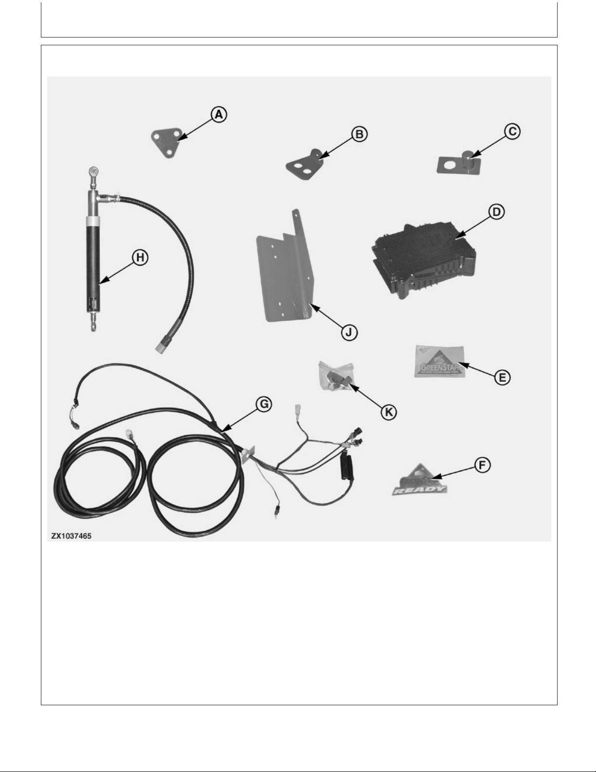
Contents of Bundle BZ13788
Installation Instructions
A—Z73362 Plate (1x) D—AZ59199 Job computer (1x) G—AZ101120 Wiring harness J—PF80209 Bracket (1x)
B—Z72204 Plate (1x) E—H204964 Decal (1x) (1x) K—AZ71569 Connector (1x)
C—AZ57754 Holder (1x) F—N302284 Decal (1x) H—AZ63280 Potentiometer
(1x)
NOTE: The bundle contains a hardware bag.
OUZXMAG,0002081 –19–03AUG05–1/1
Z103757 (13DEC06)
1
Installation Instructions
ZX1037465 –UN–13SEP05
011507
PN=3
Page 4
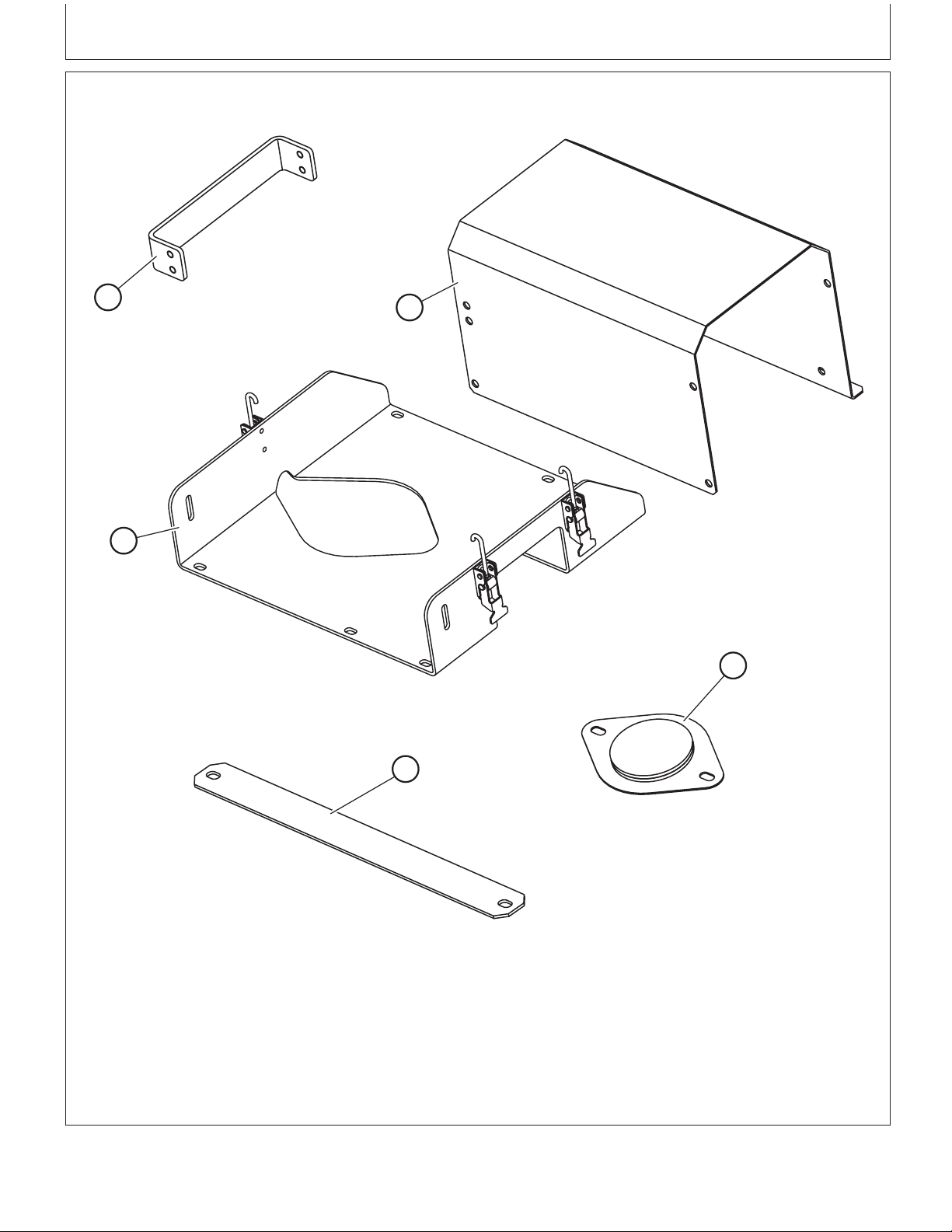
Contents of Bundle BZ100157
Installation Instructions
A
B
E
C
D
ZX1039590
A—Z102720 Support (1x) C—AZ102637 Cover Plate D—Z102760 Fixing Plate (1x) E—AZ102820 Sensor Support
B—Z101939 Shield (1x) (1x)
NOTE: The bundle contains a hardware bag including
(7x) 14M7298 M8 flange nuts, (2x) 14M7396
M8 self locking nuts, (10x) 19M7865 M8X16
Z103757 (13DEC06)
2
screws, (6x) 19M7867 M8X25 screws, (3x)
19M7897 M8X35 screws and (2x) 24M7207
8.4X24X2 washers.
OUCC002,00021C8 –19–26SEP06–1/1
Installation Instructions
ZX1039590 –UN–06SEP06
011507
PN=4
Page 5
Installation Instructions
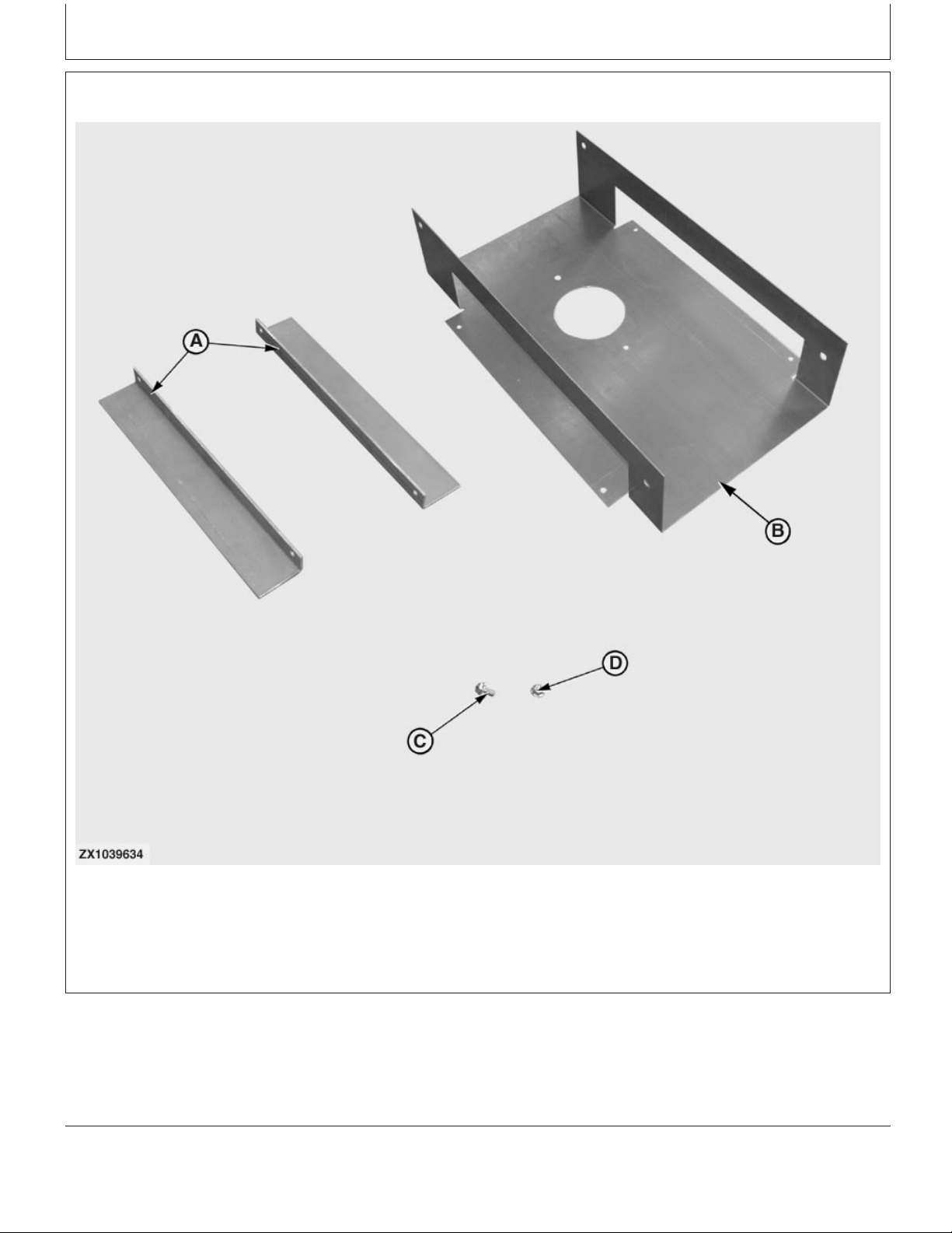
Contents of Bundle BZ100157—Continued
A—Z103667 Bracket (2x) B—Z103666 Template (1x) C—19M7865 Cap Screw M8X16 D—14M7298 Flange Nut M8
Z103757 (13DEC06)
(4x) (4x)
3
OUCC002,000233A –19–31JUL06–1/1
Installation Instructions
ZX1039634 –UN–31JUL06
011507
PN=5
Page 6
Parts to Order
Installation Instructions
B
A
ZX1039591
A—BZ100165 NIR Sensor (1x) B—AZ101740 Wear Plate for C—Z101953 Wear Plate for Flat
To complete the bundle BZ100157 installation the
parts or bundles above illustrated must be ordered
separately.
Z103757 (13DEC06)
High arc Spout (1x) Spout (1x)
4
C
OUCC002,00021C9 –19–04AUG06–1/1
Installation Instructions
ZX1039591 –UN–12JUL06
011507
PN=6
Page 7
Installation Instructions
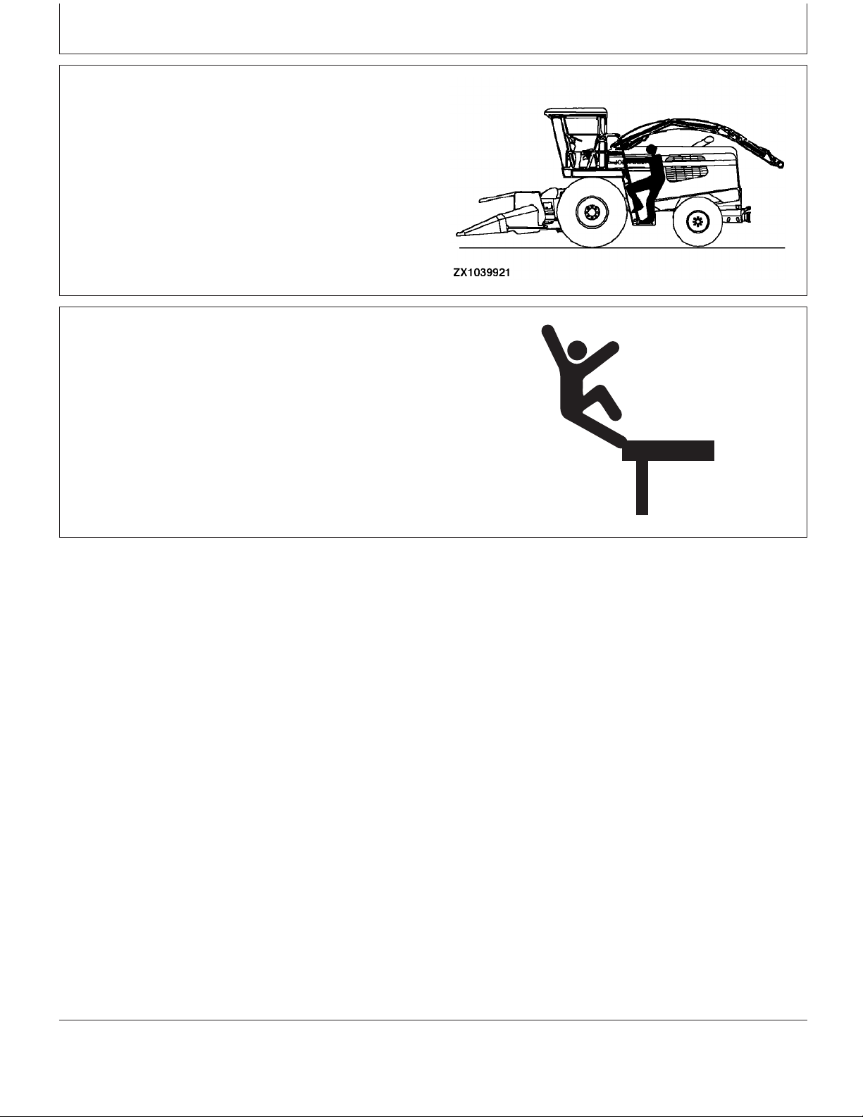
Mount and Dismount Safely With the Moisture Sensor
Hold handrail with one hand and carry the moisture
sensor with the other.
Maintain Stability
Keep work surfaces dry and clean. Maintain balance while
transporting and installing the moisture sensor onto the
forage harvester’s spout.
Care should also be observed while servicing the sensor.
ZX1039668
OUCC002,0002373 –19–06SEP06–1/1
ZX1039921 –UN–06SEP06
ZX1039668 –UN–29AUG06
OUCC002,0002374 –19–06SEP06–1/1
Z103757 (13DEC06)
5
Installation Instructions
011507
PN=7
Page 8
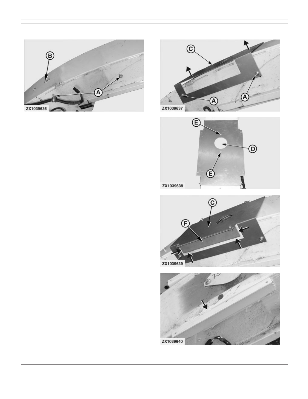
Modify High Arc Spout
Installation Instructions
ZX1039636 –UN–12JUL06
On machines with old high arc type spout, proceed as
follows to install NIR sensor brackets:
1. On both sides of the spout, release the side wear plate
fixing screws (A) and rear wear plate fixing screws (B).
Remove and discard rear wear plate. Remove both
side wear plates.
2. Install template Z103666 (C) over spout as shown
using original hardware (A). Pull up template Z103666
(C) to set it correctly in position then tighten fixing
screws (A).
3. Mark area (D) to cut a hole 102 mm (4.01 in.) diameter
then drill two holes 11x20 mm (0.43x0.78 in.) at
locations (E).
4. Install brackets Z103667 (F) on template Z103666 (C)
with four screws 19M7865 M8X16 and flange nuts
14M7298. Make sure brackets (F) are in contact with
spout sides then weld at front and rear of the brackets
(F) (see arrows) on spout.
IMPORTANT: Grind spout sides at locations where
weld will be carried out.
ZX1039637 –UN–12JUL06ZX1039638 –UN–12JUL06ZX1039639 –UN–12JUL06ZX1039640 –UN–12JUL06
5. Remove template Z103666 (C) then finalize welding
process on top of brackets Z103667 (F) (see arrow).
A—Fixing Screws
B—Fixing Screws
C—Template Z103666
D—Area to Cut
E—Drilling Holes
F—Brackets Z103667
Z103757 (13DEC06)
Continued on next page
6
OUCC002,000233C –19–12OCT06–1/2
Installation Instructions
011507
PN=8
Page 9

Installation Instructions
IMPORTANT: Grind weld at top of brackets Z103667
(F) so that weld surface is flush with the
bracket surface.
6. Cut out previously marked area (D).
OUCC002,000233C –19–12OCT06–2/2
Z103757 (13DEC06)
7
Installation Instructions
011507
PN=9
Page 10

Replace Spout Wear Plate
Installation Instructions
A
B
ZX1039595
Using original hardware, install wear plate AZ101740 (A)
on high arc type spout or wear plate Z101953 (B) on flat
spout.
On new high arc type spout, use a hammer to remove
pre-cut part (C) of spout as shown.
A—Wear plate—AZ101740—High arc spout
B—Wear plate—Z101953—Flat spout
C—Part to remove
ZX1039594
ZX1039595 –UN–10APR06
C
ZX1039594 –UN–10APR06
OUCC002,00021CE –19–12OCT06–1/1
Z103757 (13DEC06)
8
Installation Instructions
011507
PN=10
Page 11

Installation Instructions
Install NIR Sensor BZ100165
1. Pre-assemble NIR sensor BZ100165 (A) with the
shield Z101939 (B) using 6 flange screws M8X16 (C).
2. Install support Z101720 (D) using 4 flange screws
M8X16 (C).
3. Place three screws M8X35 (E) and three flange nuts
(F) on sensor support as shown.
4. Insert sealing ring Z101944 (G) on glass adapter of
sensor BZ100165 (A).
IMPORTANT: To install the sealing ring (G) correctly,
align its centering protrusion with the
groove of glass adapter.
5. Install support AZ102820 (H) on spout using four
flange screws M8X25 (I) and flange nuts.
A—NIR sensor—BZ100165
B—Shield—Z101939
C—Flange screws M8X16
D—Support Z101720
E—Flange screws M8X35
F—Flange nut
G—Sealing ring—Z101944
H—Support—AZ102820
I—Flange screws M8X25
ZX1039596 –UN–10APR06ZX1039597 –UN–10APR06ZX1039598 –UN–26SEP06
Z103757 (13DEC06)
Continued on next page
9
OUCC002,00021CD –19–18NOV06–1/4
Installation Instructions
011507
PN=11
Page 12

Installation Instructions
6. Attach sensor assembly (A) to support AZ102820 (B)
using two flange screws M8X25 (C), two washers
8.4X24X2 (D) and two self-locking nuts (E) as shown.
IMPORTANT: To ease sensor assembly fold/unfold,
place washers (D) between support (B)
and sensor assembly brackets. Do not
overtighten self-locking nuts (E). Sensor
assembly (A) must remain easily
foldable.
The NIR sensor (A) is delivered with a dedicated wave
length standard (F). To avoid NIR sensor and non
dedicated wave length standard mix up, it is strongly
recommended to report the NIR sensor serial number
on its relevant wave length standard cover (G).
IMPORTANT: Prior to operating the NIR sensor (A),
carry out an initial wave length standard
measurement as described in Harvest
Monitor System Operator’s Manual.
If the wave length standard
measurement is not successful then a
black and white calibration of the NIR
sensor is required. Proceed as
described in the forage harvester
Technical Manual.
The wave length standard (F) must be kept in good
condition for future measurement. In this way, special
attention must be paid so that the wave length
standard (F) doesn’t come in contact with chemical
products such as:
• Diesel
• Gasoline (Leaded or unleaded)
• Thinners
• Engine cleaner
• Cavity sealing
• After cleaning
• Finishing paint
• Blackboard lacquer
• Freeze protection
ZX1039599 –UN–10APR06ZX1040034 –UN–18NOV06
A—Sensor assembly
B—Support—AZ102820
C—Flange screws M8X25
D—Washers 8.4X24X2
E—Self-locking nuts
F—Wave length standard
G—Cover
Z103757 (13DEC06)
Continued on next page
10
OUCC002,00021CD –19–18NOV06–2/4
Installation Instructions
011507
PN=12
Page 13

Installation Instructions
NOTE: Do not disconnect sensor (A) from machine wiring
harness until sensor shuts down completely.
Before disconnecting sensor turn forage harvester
ignition off. Wait at least 30 seconds before
disconnecting the sensor.
Continued on next page
OUCC002,00021CD –19–18NOV06–3/4
Z103757 (13DEC06)
11
Installation Instructions
011507
PN=13
Page 14

F
Installation Instructions
E
E
A
B
ZX1039600
A—Adapter glass C—Front point setting E—Flange screw F—Flange nut
B—Wear plate D—Rear point setting
7. Place sensor into working position but do not latch
it. Adjust sensor assembly position so that tip of
adapter glass (A) is flush with wear plate (B) at
C
IMPORTANT: To allow a proper adapter glass
self-cleaning process, make sure
that sensor position is correctly set.
front point (C) and about 1 mm (0.08 in.) below
surface of wear plate (B) at rear point (D) as
NOTE: Arrow is showing the crop flow direction.
shown. Use the three flange screws (E) to adjust
then secure with flange nuts (F).
D
F
ZX1039600 –UN–10APR06
Z103757 (13DEC06)
12
OUCC002,00021CD –19–18NOV06–4/4
Installation Instructions
011507
PN=14
Page 15

Installation Instructions
Install Feed Roll Potentiometer AZ63280
Install Upper Plate Z72204 and Holder AZ57754
1. Remove right-hand feed roll spring (A) by loosening
eye-bolt (B).
2. Install plate Z72204 (C) and holder AZ57754 (D) in the
free holes.
3. Put the eye-bolt (B) back in place and tighten the
spring to its original setting.
A—Feed roll spring
B—Eye-bolt
C—Plate Z72204
D—Holder AZ57754
Continued on next page
OUZXMAG,0001BEF –19–13NOV03–1/3
ZX1034539 –UN–16NOV03
Z103757 (13DEC06)
13
Installation Instructions
011507
PN=15
Page 16

Installation Instructions
Install Lower Plate Z73362
1. Drill two 9 mm (0.35 in.) diameter holes on cutterhead
frame (A) as shown.
2. Install plate Z73362 (D) on frame (A) with two cap
screws M8x40 (E) and nuts, as shown.
A—Cutterhead frame
B—75 mm (2.95 in.)
C—34 mm (1.34 in.)
D—Plate Z73362
E—Cap screws M8x40
F—15 mm (0.59 in.)
Continued on next page
ZX1034541 –UN–18NOV03ZX1031222 –UN–02NOV02
OUZXMAG,0001BEF –19–13NOV03–2/3
Z103757 (13DEC06)
14
Installation Instructions
011507
PN=16
Page 17

Installation Instructions
Install Feed Roll Potentiometer AZ63280
1. Install potentiometer AZ63280 (A) between plate
Z72204 (B) and plate Z73362 (C) with screws (D)
M12x35, flange nuts and lock nuts as shown.
2. Connect potentiometer AZ63280 (A) to free connector
(E) of machine wiring harness.
IMPORTANT: The potentiometer (A) should be
mounted so that the wiring harness
connector is in top position.
A—Potentiometer AZ63280
B—Plate Z72204
C—Plate Z73362
D—Screws M12x35
E—Connector
OUZXMAG,0001BEF –19–13NOV03–3/3
ZX1034542 –UN–16NOV03
Z103757 (13DEC06)
15
Installation Instructions
011507
PN=17
Page 18

Installation Instructions
Install Job Computer AZ59199 and Wiring Harness AZ101120
1. Install job computer AZ59199 (A) as shown on the
bottom left side of load center with three screws M8x60
(B) using existing nuts in the wall.
2. Connect main connector (C) of wiring harness
AZ101120 (D) to job computer (A).
3. Disconnect A7-CAN bus terminator (E) located near
the board A3. Connect CAN bus terminator (E) to
relevant connector (F) of wiring harness AZ101120 (D),
then connect wiring harness AZ101120 to terminator
(E) original connector as shown.
4. Locate free connectors X27 (G) and X30 (H), then
connect them to the relevant machine wiring harness
free connections using parts of connector AZ71569 (I)
and following tables:
X27 Connector AZ71569 Pin Connections
Pin Number Wire
Pin #1 .......................................... 552C
Pin #2 .......................................... 974
Pin #3 .......................................... 975
Pin #4 .......................................... 050B
Pin #5 .......................................... not used
Pin #6 .......................................... not used
ZX1037466 –UN–13SEP05
ZX1037467 –UN–13SEP05ZX1037468 –UN–13SEP05ZX1037469 –UN–13SEP05
A—Job computer AZ59199
B—Screws M8x60
C—Main connector
D—Wiring harness AZ101120
E—A7 CAN bus terminator
F—Connector
G—X27 Connector
H—X30 Connector
I—AZ71569 Connector
Z103757 (13DEC06)
Continued on next page
16
OUCC002,00021CA –19–18NOV06–1/8
Installation Instructions
011507
PN=18
Page 19

X30 Connector AZ71569 Pin Connections
Pin Number Wire
Pin #1 .......................................... 584
Pin #2 .......................................... 586
Pin #3 .......................................... 585
Pin #4 .......................................... 571
Pin #5 .......................................... not used
Pin #6 .......................................... not used
Installation Instructions
OUCC002,00021CA –19–18NOV06–2/8
5. Connect part of wiring harness AZ101120 with
15A-fuse (A) to connecting point 002 (B) located on
board A3 as shown.
6. Remove closing plate from bottom of load center (not
illustrated) and pass wiring harness AZ101120 (C)
through the opening until guide plate (D) can be
installed using original hardware previously removed.
A—Fuse
B—Connecting point
C—Wiring harness AZ101120
D—Guide plate
ZX1037470 –UN–13SEP05ZX1037471 –UN–13SEP05
Z103757 (13DEC06)
Continued on next page
17
OUCC002,00021CA –19–18NOV06–3/8
Installation Instructions
011507
PN=19
Page 20

Installation Instructions
A—Inoculant dosing device B—NIR sensor connector C—Wiring harness AZ101120 D—Connection box
connector
7. Using above illustration, route connectors (A) and
(B) of wiring harness AZ101120 (C) underneath the
Z103757 (13DEC06)
18
connection box (D), alongside the left-hand side of
machine frame then behind the cab.
Continued on next page
OUCC002,00021CA –19–18NOV06–4/8
Installation Instructions
ZX1037472 –UN–13SEP05
011507
PN=20
Page 21

Installation Instructions
IMPORTANT: Route wiring harness AZ101120 (C)
alongside machine wiring harness
and secure with tie bands.
NOTE: Connector (A) shall be used for inoculant
dosing device connection.
Connector (B) shall be stored in a safe place if
NIR sensor is not installed on spout.
8. Route inoculant dosing device connector (A) outside
the rear right-hand side of the cab as shown.
9. Drill a suitable hole near the cab closing plate (B) so
that connector sleeve (C) can be inserted and fixed to
the cab wall as shown.
IMPORTANT: Open plate (B) and check that no wiring
harness is being damaged while drilling
the hole!
NOTE: Use the existing machine wiring harnesses
and/or hydraulic hoses to fix the wiring
harness AZ101120 (C) with plastic clamps so
that it will not be left loose in a way it can be
caught by any moving part.
OUCC002,00021CA –19–18NOV06–5/8
-If an inoculant dosing device is used, route dosing
device connecting wires through opening of closing
plate and refer to “Connecting Inoculant Dosing
Device” for proper device connection.
-If no inoculant dosing device is used, keep connector
(A) protected behind closing plate (B).
A—Connector for inoculant dosing device
B—Closing plate
C—Connector sleeve
10. In Case Bundles BZ100157 and BZ100165 are Not
Installed on Spout:
Route and store NIR sensor connector (A) near the
spout motor (B). Make sure to store the cable so that
it will not be caught by any moving part.
ZX1037996 –UN–13SEP05ZX1037997 –UN–13SEP05
OUCC002,00021CA –19–18NOV06–6/8
A—NIR sensor connector
B—Spout motor
Z103757 (13DEC06)
Continued on next page
19
OUCC002,00021CA –19–18NOV06–7/8
Installation Instructions
011507
PN=21
ZX1037998 –UN–13SEP05
Page 22

Installation Instructions
11. In Case Bundles BZ100157 and BZ100165 are
Installed on Spout:
Route NIR sensor connector (A) to the right-hand side
of the spout motor (B) then alongside the spout wiring
harness (C) up to the NIR sensor BZ100165 (D) as
shown. Secure cable with tie bands.
Make sure to route the cable so that it will not be
caught by any moving part.
12. Connect NIR sensor connector (A) to NIR sensor
BZ100165 (D) then engage the three latches (E) to
maintain NIR sensor BZ100165 (D) in working
position as shown.
IMPORTANT: Route cable as shown on illustration
and make sure to keep sufficient play to
cable so that NIR sensor assembly can
be folded/unfolded without
disconnecting connector (A).
NOTE: If connection box BZ100168 has been installed on
NIR sensor BZ100165 then connect NIR
connector (A) to the connection box (not
illustrated).
NOTE: Do not disconnect sensor (D) from spout wiring
harness until sensor shuts down completely.
Before disconnecting sensor turn forage harvester
ignition off. Wait at least 30 seconds prior to
disconnecting the sensor.
A—NIR sensor connector
B—Spout motor
C—Spout wiring harness
D—NIR sensor—BZ100165
E—Latch (3 used)
ZX1037998 –UN–13SEP05ZX1039592 –UN–10APR06
Z103757 (13DEC06)
20
OUCC002,00021CA –19–18NOV06–8/8
Installation Instructions
011507
PN=22
Page 23

Installation Instructions
Connecting Inoculant Dosing Device
To enable the dosing device system, the connector (A)
MUST be connected to the relevant connector of inoculant
dosing device control unit in the following manner (refer to
table for connector (A) pin connections).
• Tx wire1of dosing device connector to Rx wire2of
wiring harness AZ101120 connector (A).
• GND wire3of dosing device connector to GND wire of
wiring harness AZ101120 connector (A).
ZX1037996 –UN–13SEP05
• Rx wire of dosing device connector to Tx wire of wiring
harness AZ101120 connector (A).
Connector (A) Pin Connections
Pin Number Wire
Pin #A .......................................... 589—Tx
Pin #B .......................................... 590—GND
Pin #C ......................................... 591—Rx
1
Tx wire: Means wire that transmits the signal
2
Rx wire: Means wire that receives the signal
A—Connector for inoculant dosing device
3
GND wire: Means ground wire
Z103757 (13DEC06)
21
OUZXMAG,00020A0 –19–13SEP05–1/1
Installation Instructions
011507
PN=23
Page 24

Installation Instructions
Install Bracket PF80209 in Cab
1. Install monitor bracket PF80209 (A) on right-hand
corner post as shown using corner post fixing screws
(B).
2. Pull down cab roof trim (C) and look for monitor wiring
harness (D). Extract it from cab roof and route it up to
the bracket PF80209 as shown. Keep the wiring
harness (D) connectors free for further monitor
installation.
A—Bracket PF80209
B—Screws
C—Cab roof trim
D—Monitor wiring harness
ZX1034544 –UN–16NOV03ZX1034545 –UN–16NOV03
OUZXMAG,0001BF0 –19–16NOV03–1/1
Z103757 (13DEC06)
22
Installation Instructions
011507
PN=24
Page 25

Installation Instructions
Attach GreenStar Decals
• Attach decal H204964 (A) to left hand side of the
harvester as indicated.
• Attach decal N302284 (B) as indicated in front of the
display (C), on inside of cab.
A—Decal H204964
B—Decal N302284
C—Display
OUZXMAG,00020A1 –19–14SEP05–1/1
ZX1031229 –UN–02NOV02ZX1031230 –UN–02NOV02
Z103757 (13DEC06)
23
Installation Instructions
011507
PN=25
Page 26

Installation Instructions
Load Software
Load Display Software
To load new software:
1. Install PC Card containing NEW software in card slot A
of mapping processor.
2. Turn ignition key to RUN position.
3. Press “INFO” key to enter INFO mode.
4. Press key B in “INFO” to select “Keycard”.
5. Press key A to select “Devices on CAN Bus”. Actual
Version Display Software and Version Harvest Mon
are then displayed.
6. Press key G once to go back.
7. Press key C to select “Program Target”.
8. Press key A to select “GreenStar Display”.
9. Press relevant key to choose “PF303182B” software
version, or higher.
10. While programming (about 30 seconds):
- DO NOT REMOVE PC CARD
- DO NOT REMOVE POWER
11. When programming is complete, the
PROGRAMMING COMPLETE screen will appear.
CYCLE POWER will be displayed in lower left
corner.
Turn ignition switch OFF.
Load Job Computer Software
To load new software:
1. Install PC Card containing NEW software in card slot A
of mapping processor.
2. Turn ignition key to RUN position.
Z103757 (13DEC06)
Continued on next page
24
OUZXMAG,0002083 –19–04AUG05–1/2
Installation Instructions
011507
PN=26
Page 27

Installation Instructions
3. Press “INFO” key to enter INFO mode.
4. Press key B in “INFO” to select “Keycard”.
5. Press key A to select “Devices on CAN Bus”. Actual
Version Display Software and Version Harvest Mon
are then displayed.
6. Press key G once to go back.
7. Press key C to select “Program Target”.
8. Press key A to select “Harvest Mon”.
9. Press relevant key to choose “PF311135C” software
version, or higher.
10. While programming (about 30 seconds):
- DO NOT REMOVE PC CARD
- DO NOT REMOVE POWER
11. When programming is complete, the
PROGRAMMING COMPLETE screen will appear.
CYCLE POWER will be displayed in lower left
corner.
Turn ignition switch OFF.
OUZXMAG,0002083 –19–04AUG05–2/2
Z103757 (13DEC06)
25
Installation Instructions
011507
PN=27
Page 28

Installation Instructions
Check Yield Monitoring Functionality
Calibrate Mass-Flow Sensor
1. Turn ignition key to RUN position.
2. Press “SETUP” key to enter SETUP mode.
3. Press key C in “SETUP” to select “GreenStar
Display”.
4. Select your native language and units then press key
G once to go back.
5. Press key A to select “Harvest Mon”.
6. Make sure that “Recording ON/OFF By:” is set on
“HEADER” then press key G once to go back.
7. Press key D to select “Yield Calibration”.
8. Press key A to start calibration. Wait until feedroll
height is 10 mm (0.4 in.).
9. Press RUN key.
Check Monitoring Functions
1. Turn ignition key to start harvester engine.
2. Press “INFO” key to enter INFO mode.
3. Press key A in “INFO” to select “Harvest Mon”.
4. Press key F to select “Diagnostics”.
5. Press key B to select “Mass-Flow System”. Engage
main clutch and harvesting unit then check the
following points:
• Height right—should be between 0.2 and 0.6 V.
• Vref—Should be between 4.8 and 5.1 V.
If any of these points are not OK, contact your John
Deere dealer.
Press key G once to go back.
Z103757 (13DEC06)
Continued on next page
26
OUZXMAG,0001BF6 –19–18NOV03–1/2
Installation Instructions
011507
PN=28
Page 29

Installation Instructions
6. Press key C to select “SPFH Network” and check
communication between SPFH and Harvest Monitor.
7. Press RUN key.
Check Inoculant Dosing Functionality
1. Turn ignition key to start harvester engine.
2. Press “SETUP” key to enter SETUP mode.
3. Press key A in “SETUP” to select “Harvest Mon”.
4. Press “PAGE” key to go to “SETUP - Harv Mon PAGE 2” screen then press key “F” to toggle inoculant
dosing support state from OFF to ON or vice versa.
5. Press RUN key.
6. The inoculant dosing device can be engaged if:
OUZXMAG,0001BF6 –19–18NOV03–2/2
ZX1035268 –UN–26JUL04
• The road safety switch is in field operating mode
• The forage harvester is travelling forward
• The ground speed is greater than 2 km/h (1.24 mph)
• The feedrolls are turning in forward direction
• The header is in harvesting position
7. Press once the liquid injection pump switch (A). Carry
out a test to make sure that inoculant device is
properly connected to the wiring harness AZ101120.
If this is not the case check wiring harness connection
or contact your John Deere dealer.
NOTE: For a proper use of the liquid injection pump
switch (A), refer to the forage harvester Operator’s
Manual.
Z103757 (13DEC06)
27
OUZXMAG,0002084 –19–04AUG05–1/1
Installation Instructions
011507
PN=29
Page 30

Installation Instructions
Use of Cover Plate AZ102637
In case the spout is operated without the NIR sensor it is
necessary to install cover plate AZ102637 (A) to close
opening in wear plate AZ101740 or Z101953.
NOTE: The illustration shows the cover plate AZ102637
(A) installed on a high arc type spout. In case of
flat spout, it is necessary to use the supplied
fixing plate Z102760 to maintain cover plate
AZ102637 in place using original spout wear plate
fixing hardware—Not illustrated.
A—Cover Plate—AZ102637
ZX1039593 –UN–10APR06
OUCC002,00021CF –19–18JUL06–1/1
Z103757 (13DEC06)
28
Installation Instructions
011507
PN=30
 Loading...