

Page 1
4630
SelfPropelled
Sprayer
(Serial No. N04630X000101 )
OPERATOR’S MANUAL
4630 SelfPropelled Sprayer
OMN300896 ISSUE L9 (ENGLISH)
DCYOMN300896
CALIFORNIA
Proposition 65 Warning
Diesel engine exhaust and some of its constituents
are known to the State of California to cause cancer,
birth defects, and other reproductive harm.
If this product contains a gasoline engine:
WARNING
The engine exhaust from this product contains
chemicals known to the State of California to cause
cancer, birth defects or other reproductive harm.
The State of California requires the above two warnings.
John Deere Des Moines Works
LITHO IN U.S.A.
Downloaded from manualsnet.com search engine
Page 2

Foreword
Introduction
READ THIS MANUAL carefully to learn how to operate
and service your machine correctly. Failure to do so
could result in personal injury or equipment damage.
This manual and safety signs on your machine may also
be available in other languages. (See your John Deere
dealer to order.)
THIS MANUAL SHOULD BE CONSIDERED a permanent
part of your machine and should remain with the machine
when you sell it.
MEASUREMENTS in this manual are given in both
metric and customary U.S. unit equivalents. Use only
correct replacement parts and fasteners. Metric and inch
fasteners may require a specific metric or inch wrench.
RIGHTHAND AND LEFTHAND sides are determined by
facing in the direction of forward travel.
WRITE PRODUCT IDENTIFICATION NUMBERS (P.I.N.)
in the Specification or Identification Numbers section.
Accurately record all the numbers to help in tracing the
machine should it be stolen. Your dealer also needs these
numbers when you order parts. File the identification
numbers in a secure place off the machine.
WARRANTY is provided as part of John Deere’s support
program for customers who operate and maintain their
equipment as described in this manual. The warranty is
explained on the warranty certificate or statement which
you should have received from your dealer.
This warranty provides you the assurance that John
Deere will back its products where defects appear within
the warranty period. In some circumstances, John Deere
also provides field improvements, often without charge
to the customer, even if the product is out of warranty.
Should the equipment be abused, or modified to change
its performance beyond the original factory specifications,
the warranty will become void and field improvements
may be denied. Setting fuel delivery above specifications
or otherwise overpowering machines will result in such
action.
THE TIRE MANUFACTURER’S warranty supplied with
your machine may not apply outside the U.S.
If you are not the original owner of this machine, it is in
your interest to contact your local John Deere dealer to
inform them of this unit’s serial number. This will help John
Deere notify you of any issues or product improvements.
DX,IFC1 1903APR091/1
Downloaded from manualsnet.com search engine
122309
PN=2
Page 3

Contents
Page
Safety.......................................................... 051
Safety Signs
Safety Signs .......................................................101
Safety Features
Safety Features ..................................................151
Operators Station
Front Console ..................................................... 201
Key Switch..........................................................202
Adjust Steering Wheel........................................202
Operate Turn Signals ......................................... 203
Operate the Hazard Warning Light Switch .........203
Operate Windshield Wiper..................................203
Operate Horn......................................................204
Operate Light Switch and High/Low
Beam Switch ..................................................204
Light Operation Table .........................................205
Side Console Switches.......................................206
Side Console Switches.......................................206
Operate Boom Section Switches........................207
Rate Select Switch .............................................207
Accessory Electrical Outlet................................. 208
CommandARM™ Controls ................................. 208
Multifunction Control Handle ..............................209
Foam Marker Switch—If Equipped...................2010
Speed Range Switch........................................2010
Spray System Master ON/OFF Switch .............2011
Boom Raise/Lower Switches............................ 2012
IBS Index Boom Section Buttons ..................... 2012
Solution Pump Switch.......................................2013
Agitation Switch ................................................ 2013
Lefthand and Righthand Fence Row
Nozzles Switches—If Equipped ...................2013
Ladder Switch...................................................2014
Tread Adjust Switches ......................................2014
Throttle .............................................................2014
Storage Rack....................................................2015
Load Center......................................................2015
Diagnostic Outlet ..............................................2015
Heater and Air Conditioning Controls ...............2016
Fan and Air Louvers .........................................2016
Heater............................................................... 2016
Air Conditioning System ................................... 2017
Operating Tips About Your Audio System ........2017
Page
DeereDelco AM/FM Stereo Radio, CD
Player, and Weatherband............................. 2018
Program Radio for Local Area Frequency ........2021
Weatherband....................................................2021
Dome Light and Console Light .........................2022
Switches at BPost ...........................................2022
Using Secondary Brake....................................2023
Traction Control (Optional) ...............................2023
Operate Beacon Light (If Equipped) .................2024
Operator’s Seat ................................................2024
Operator's Seat
Seat Belt....................................................... 2025
Instructional Seat—If Equipped........................2025
Adjust Rearview Mirrors ...................................2025
Breakin Period
Engine ................................................................251
Prestarting Checks
Check Engine Oil Level—Daily...........................301
Drain Water and Sediment from Fuel
Filter and Water Separator—Daily .................301
Check Coolant Level—Daily............................... 301
Check Hydrostatic and Hydraulic Oil
Level—Daily ...................................................302
Fill Fuel Tank ......................................................302
Check Tires For Damage And Correct
Inflation Pressure—Daily................................ 303
Check Air Springs—Daily (Machines
not Equipped with Auto Air Spring
Leveling System)............................................ 303
Lubricate Suspension Assemblies—Daily..........304
Drain Moisture from On Board Air Tank—Daily .. 305
Operating The Machine
Machine Informational Decals ............................ 351
Start the Engine..................................................351
Cold Weather Starting ........................................353
Warm The Engine...............................................353
Idle the Engine....................................................354
Operate the Engine ............................................354
Operate Warning Lights......................................354
Driving the Machine............................................355
Backup Alarm .....................................................356
Before Operating in the Field.............................. 356
Operate in the Field ............................................356
Operate Traction Control (Optional) ...................359
Original Instructions. All information, illustrations and specifications in this
manual are based on the latest information available at the time of publication.
The right is reserved to make changes at any time without notice.
Downloaded from manualsnet.com search engine
Continued on next page
COPYRIGHT © 2009
DEERE & COMPANY
Moline, Illinois
A John Deere ILLUSTRUCTION ® Manual
i
All rights reserved.
122309
PN=1
Page 4

Contents
Page
Operate IBS........................................................359
Operate Boom Return to Height .......................3511
Reduce Travel Speed .......................................3512
Verify Proper Operation Of Park Brakes........... 3513
Relieve Boom Pressure.................................... 3513
Transport Machine............................................3514
Mired Machine .................................................. 3515
Park the Machine..............................................3517
SprayStar System
Display Theory of Operation...............................401
Front of Display ..................................................402
Back of Display...................................................403
Display Secondary Navigation............................403
Data Card ...........................................................404
Screen Layout ....................................................405
Power Up............................................................406
Input Fields ......................................................... 407
ISO Standard Icons ............................................ 408
Message Center .................................................408
Display.............................................................. 4010
Display
Display Softkey (F)......................................4012
Application Menu .............................................. 4015
Settings Softkey (G)....................................4016
Diagnostics Softkey (I) ................................4017
Layout Manager................................................4017
Resetting Display..............................................4022
GS2 1800 Display Features .............................4023
Front of Display—GS2 1800 Display ................4024
Back of Display—GS2 1800 Display ................4025
Turn The Display On/Off—GS2 1800 Display ..4025
Navigate Your GS2 1800 Display .....................4026
Display Menu—GS2 1800 Display ...................4029
Adjust Volume And Brightness—GS2
1800 Display ................................................ 4030
Change Regional Settings—GS2 1800
Display .........................................................4031
Set The Time And Date—GS2 1800 Display ...4032
Set the Highlight Color—GS2 1800 Display .....4033
Choose Home Pages For Your
Display—GS2 1800 Display.........................4034
SprayStar System.............................................4034
Sprayer Main Page...........................................4035
Sprayer Main Page Information Drop
Down Lists.................................................... 4036
Spray Setup......................................................4037
Set Application Rates ....................................... 4038
Set Minimum Pressure ..................................... 4039
Set Spray Off Pressure.....................................4041
Set Tank Reset Volume .................................... 4042
Set Sprayer Response .....................................4043
Setup Boom Charge.........................................4044
Set Manual Pressure........................................4046
Foam Marker ....................................................4047
Enable Boom Pressure Relief ..........................4048
Turn Flow Rate Alarm On/Off ...........................4049
Turn Sections Off Alarm On/Off........................4050
Page
Set Number of Boom Sections,
Number of Nozzles and Spacing..................4051
Program SprayStar for Band Spraying .............4053
Setup Boom Return To Height..........................4055
Recording Engine Hours ..................................4056
Resetting Service Interval Counter...................4057
Setting Time and Date......................................4058
Setting Vehicle Speed Selection....................... 4059
Set Flowmeter Calibration Number ..................4060
Calibrate Pressure Sensor ...............................4061
Calibrate Solution Pump...................................4063
Reset Spray Calibrations to Factory
Default Settings ............................................4065
Calibrate Boom Return To Height..................... 4067
Calibrating Wheel Speed Sensor .....................4069
Calibrating Radar Sensor (Optional) ................4071
Controller Diagnostics ......................................4073
Diagnostic Readings.........................................4074
Diagnostic Tests ...............................................4075
Recent Problems .............................................. 4076
Job Summaries and Current Totals ..................4077
Operating Distance Counter.............................4080
Refill Tank .........................................................4081
Nozzle Flow Check Test ...................................4082
Fence Row Nozzles—If Equipped....................4083
Applying Low Application Rates .......................4084
Control Unit Info................................................4084
SprayStar Caution and Warning Statements....4085
Message Center Cautions and Warnings .........4085
Warning ............................................................4086
Chassis Caution Alarms ................................... 4086
Park Brake On..................................................4086
Secondary Brake On ........................................ 4086
Low Fuel ........................................................... 4086
Scheduled Maintenance/Service is Due...........4087
SprayStar: System Error—Data May
Be Lost .........................................................4087
SprayStar: Fuel Sensor Error—Out of
Range High .................................................. 4087
SprayStar: Fuel Sensor Error—Out of
Range Low ...................................................4087
Solution System Caution Alarms ...................... 4087
Solution Flow is Low.........................................4087
Solution Flow is High ........................................ 4087
SprayStar—Solution Pressure Sensor
Failure ..........................................................4088
Calibration in Progress—Please Wait... ...........4088
Pump Calibration Disabled!—Review
Calibrate Checklist ....................................... 4088
Boom Sections Are Off .....................................4088
Spraying is Disabled in Fourth Range ..............4088
Remote Load Disabled—Check
Remote Switch .............................................4088
Boom Sensors Are Out Of Calibration..............4088
SprayStar: Boom Return To Height
Sensor Failure ..............................................4089
Engine Caution Alarms.....................................4089
Engine System: 94.17 Fuel Pressure Low..... 4089
Downloaded from manualsnet.com search engine
Continued on next page
ii
122309
PN=2
Page 5

Contents
Page
Engine System: 97.16 – Water in Fuel
Detected.......................................................4089
Engine System: 105.16 – Engine Air
Temperature High.........................................4089
Engine System: 107.0 – Air Filter Restricted ... 4089
Engine System: 110.15 – Coolant
Temperature High.........................................4089
Engine System: 110.16 – Coolant
Temperature High.........................................4090
Engine System: 174.16 – Fuel
Temperature High.........................................4090
Engine System: 1638.16 – Hydraulic
Oil Hot .......................................................... 4090
Chassis Warning Alarms ..................................4090
Secondary Brake Is On ....................................4090
Solution System Warning Alarms ..................... 4090
Solution Pump is Dry Turn Off Pump
Immediately..................................................4090
Engine Warning Alarms ....................................4090
Engine System: 100.1 Engine Oil
Pressure Low ............................................... 4090
Engine System: 110.0 Coolant
Temperature High.........................................4091
Engine System: 190.0 Engine Speed
Too High .......................................................4091
Engine System: 1638.0 Hydraulic Oil Hot .......4091
Wet System
Solution System..................................................451
Avoid Contact with Chemicals,
Including Pesticides ....................................... 453
Solution Pump Maintenance and
Operation Recommendations ........................ 454
Replacing Nozzles..............................................456
Nozzle Types......................................................456
Flat Fan Nozzle ..................................................457
Even Spray Nozzle.............................................458
Hollow Cone Nozzle ........................................... 459
Flood Nozzle.....................................................4510
Flat Fan High Flow (Flood) Nozzle ...................4510
Using Nozzle Tip Calculator and Selector ........ 4511
Checking and Replacing Worn Nozzles ...........4512
24.4 M (80 ft) Boom Flow
Characteristics—Application
Rate vs. Speed ............................................ 4513
Boom Flow Characteristics (Standard
Flow)—Boom Flow Rate vs.
Pressure 24.4 M (80 ft.) Boom.....................4514
Calibrating Nozzles...........................................4515
Calibration Procedure.......................................4515
Conversion Factors (Calibrating for
Carriers Other Than Water)..........................4516
Installing and Positioning Nozzle Tips
and Strainers ................................................4516
Clean SprayMaster Triplet Nozzle Bodies........4518
Cleaning SprayMaster 5Position
Nozzle Bodies .............................................. 4519
Wet System Valves...........................................4520
Page
Solution Strainers .............................................4523
Filling Solution Tank Without Using
QuikFill ........................................................4524
Filling Rinse Tank Using LeftHand
Rinse Fill ...................................................... 4524
Filling Solution Tank with Sprayer Pump ..........4524
Priming Solution Pump with Rinse
Tank to Fill When Nurse Tank Fluid
Level Even or Below Sprayer Pump ............4526
Fill Solution Tank with Sprayer Pump
Through Eductor .......................................... 4527
Filling Solution Tank with Nurse Tank Pump.....4530
Fill Solution Tank with Nurse Tank
Pump and Sprayer Pump Through
Eductor.........................................................4531
Mixing Solution in Tank (Using Agitation) .........4534
Preparing to Spray............................................4535
Applying Low Application Rates .......................4536
Using Rinse System (Rinsing Solution
Tank and Boom) ...........................................4537
Use Rinse System (Rinsing Solution
Pump, Boom, and Flowmeter Only) .............4541
Recommendations For Eliminating Air
from Solution System ...................................4541
Relieve Boom Pressure.................................... 4542
Relieve Boom Pressure.................................... 4543
Clean Fill Strainer.............................................4544
Draining Solution Tank......................................4545
Cleaning Boom Supply Line
Strainer(s)—Daily.........................................4545
Clean Flowmeter—Daily...................................4546
Clean Water Tank.............................................4547
24.4 m (80 ft) Booms
Unfold Boom.......................................................501
Unfold Boom In Limited Height Area ..................503
Fold Boom ..........................................................506
Fold Boom In Limited Height Area......................508
Spray with Boom at 18.3 m (60 ft) ....................5010
Adjust Breakaway Section Springs...................5010
Adjust Roll Suspension Springs .......................5010
Adjust Boom Stop Bolts.................................... 5011
Adjusting Inner Fold Cylinder ........................... 5011
Foam Marker
On Board Air (OBA) Foam Marker
Schematic and Operation...............................551
Foam Marker System (With Internal
12volt Compressor) Schematic and
Operation .......................................................553
Operate Foam Marker System ...........................554
Use John Deere Foam and Marking
Chemicals ......................................................557
Electrical System Service
Basic Electrical Component Handling /
Precautions For Vehicles Equipped
With Computer Controlled Systems ...............601
Downloaded from manualsnet.com search engine
iii
Continued on next page
122309
PN=3
Page 6

Contents
Page
Welding Near Electronic Control Units ...............601
Keep Electronic Control Unit
Connectors Clean .......................................... 602
Prevent Acid Burns.............................................602
Service Batteries ................................................603
Prevent Battery Damage .................................... 603
Connection To A Booster Battery or Charger .....604
Charge Batteries (Removed From Machine) ......604
Safety Rules When Replacing Halogen Bulbs ...605
Replace Hood Grille Work Light Bulb .................606
Replace High and Low Beam Light Bulbs .......... 606
Adjust the Headlights..........................................608
Replace Fill Station Light Halogen Bulb ...........6010
Replace Platform Light Halogen Bulb...............6010
Replace Roof Flood Light Halogen Bulb .......... 6011
Replace Extremity Front Warning Light Bulb....6012
Replace Rear Warning Light Bulbs ..................6013
Replace Dome Light Bulb.................................6014
Safeguard Alternator and Regulator.................6015
Load Center Fuses...........................................6015
Load Center Relays and Diodes.......................6016
Fuses and Relays in the Engine
Compartment ...............................................6017
Cab and Air Conditioning
Avoid Exposure to Chemicals.............................651
Cab Pressure Indicator.......................................651
Cab Air Filters.....................................................651
Change Cab Air Filters .......................................652
Service Air Conditioner....................................... 658
Engine and Drive Train
Replace Fan Belt................................................701
Replace Alternator Belt.......................................702
Fan Belt Routing.................................................703
Inspecting Fan Belt Tensioner ............................704
Do Not Modify Fuel System ................................706
Do Not Open HighPressure Fuel System..........706
Relieve Fuel System Pressure ...........................707
Drain Water and Sediment from Fuel
Filter and Water Separator—Daily ................. 707
Replace Fuel Filters—500 Hours .......................708
Bleeding Fuel System.........................................708
Engine Air Filter..................................................709
Clean Primary Engine Air Filter Element ............709
Service Engine Air Intake and
PreCleaner—750 Hours.............................. 7010
Replace Primary and Secondary
Engine Air Filters—1500 Hours or
Two Years.....................................................7010
Secondary (Safety) Element............................. 7011
Clean Cooling Package.................................... 7011
Wheels and Tires
Use Proper Lifting Equipment.............................751
Check Tires For Damage And Correct
Inflation Pressure—Daily................................ 751
Attach Lift Bracket ..............................................752
Page
Tighten Wheel Hardware ....................................753
Install Optional Tires...........................................753
Check Front Axle ToeIn—Annually....................754
Adjust Front Axle ToeIn (Wide Machine) ........... 756
Adjust Front Axle ToeIn (Narrow Machine)........757
Discarded Tires ..................................................757
Chassis
Additional Service Information............................ 801
Set Tread Width Narrow Machine ...................... 801
Set Tread Width Wide Machine—With
out Hydraulic Tread Adjust Option .................806
Set Tread Width—With Hydraulic
Tread Adjust Option ..................................... 8011
Check Air Springs—Daily (Machines
not Equipped with Auto Air Spring
Leveling System).......................................... 8012
Auto Air Spring Leveling System ......................8013
Follow Safe Transport Procedures ................... 8013
Towing The Sprayer..........................................8013
Bleed Service Brakes ....................................... 8014
Prepare Machine For Transport on
SemiTractor Trailer .....................................8014
Checking Engine Compartment for
Accumulated Trash and Debris....................8016
Determining When to Adjust Shim Gap
on Axle Tread Adjust ....................................8016
Adjust Shim Gap with Wheel Off
Ground (Preferred) .......................................8017
Adjust Shim Gap with Wheel on Ground ..........8019
Install Fire Extinguisher (If Equipped)...............8021
Fuels, Lubricants and Coolants
Diesel Fuel..........................................................851
Handling and Storing Diesel Fuel .......................851
Biodiesel Fuel ..................................................... 852
Lubricity of Diesel Fuel .......................................853
Heavy Duty Diesel Engine Coolant .................... 853
Drain Intervals for Diesel Engine Coolant...........854
John Deere COOLGARD™ II
COOLANT EXTENDER .................................854
Supplemental Coolant Additives.........................855
Operating in Warm Temperature Climates .........855
Additional Information About Diesel
Engine Coolants and John Deere
COOLGARD™ II COOLANT EXTENDER ....856
Testing Diesel Engine Coolant............................857
Diesel Engine BreakIn Oil .................................857
BreakIn Oil Recommendations for
4630 Sprayers ................................................858
Diesel Engine Oil................................................859
Diesel Engine Oil and Filter Service Intervals ..8510
Diesel Engine Oil and Filter Service
Intervals For 4630 Sprayers......................... 8511
Extended Diesel Engine Oil Service Intervals ..8512
Hydrostatic/Hydraulic Drive Oil......................... 8512
Planetary Hub Oil .............................................8513
Grease.............................................................. 8513
Downloaded from manualsnet.com search engine
iv
Continued on next page
122309
PN=4
Page 7

Contents
Page
Suspension and Steering Grease.....................8513
Lubricant Storage .............................................8514
Alternative and Synthetic Lubricants ................8514
Lubrication and Maintenance
Lubrication Symbols ...........................................901
Prevent Hydraulic System Contamination .......... 901
Dispose of Waste Properly ................................. 901
Service Intervals—4630 (Excluding Boom) ........ 902
Tighten Lug Nuts—After First Hour ....................903
Check Solution Tank Straps—After
First Ten Hours...............................................903
Change Planetary Hub Oil—After First
50 Hours......................................................... 904
Visually Inspect Suspension
Bushings—After First 50 and
First 100 Hours...............................................904
Check Suspension Rod
Hardware—After First 100 Hours...................904
Check Shim Gap on Axle Tread
Adjust—After First 100 Hours ........................905
Change Engine Oil and Filter—After
First 100 Hours...............................................906
Check Engine Oil Level—Daily...........................907
Check Coolant Level—Daily............................... 907
Check Hydrostatic and Hydraulic Oil
Level—Daily ...................................................908
Drain Water and Sediment from Fuel
Filter and Water Separator—Daily ................. 908
Lubricate Suspension Assemblies—Daily..........909
Rinse Solution Pump, Boom, and
Flowmeter—Daily.........................................9010
Drain Moisture from On Board Air
Tank—Daily .................................................. 9010
Check Tires For Damage And Correct
Inflation Pressure—Daily.............................. 9011
Check Air Springs—Daily (Machines
not Equipped with Auto Air Spring
Leveling System).......................................... 9011
Clean Flowmeter—Daily...................................9012
Clean Screens and Cooling
Package—As Required ................................9013
Clean Fill Strainer—As Required......................9013
Replace Engine Air Filters—As Required.........9013
Inspect and Replace Fan Belt—As Required ...9013
Check and Replace Cab Air Filters—As
Required.......................................................9013
Lubricate Steering Cylinder Ball
Joints—100 Hours........................................ 9014
Visually Inspect Service Brake
Components—100 Hours............................. 9014
Tighten Wheel Hardware—100 Hours..............9015
Check Shim Gap on Axle Tread
Adjust—250 Hours .......................................9015
Change Engine Oil and Filter—250 Hours .......9016
Check Solution Tank Straps—250 Hours ......... 9017
Lubricate Drive Shaft UJoints—Every
250 Hours..................................................... 9017
Page
Service Batteries—250 Hours .......................... 9018
Rotate Tires—250 Hours ..................................9018
Check and Replace Cab Air
Filters—250 Hours or Annually .................... 9019
Replace Hydrostatic and Hydraulic
Filters—500 Hours ....................................... 9019
Change Hydraulic Oil—500 Hours ...................9020
Change Planetary Hub Oil—500 Hours............9020
Replace Fuel Filters—500 Hours .....................9021
Visually Inspect Suspension
Bushings—500 Hours .................................. 9022
Check Suspension Rod
Hardware—500 Hours ................................. 9022
Inspect Seat Belt—Annually.............................9022
Replace Air Drier Cartridge—Annually ............. 9023
Clean Engine Vent Tube—Annually ................. 9023
Inspect Service Brake Compo
nents—Annually ...........................................9024
Inspect Hydro Isolators—Annually ................... 9025
Check Front Axle ToeIn—Annually..................9026
Clean Sprayer and Coat Exposed Surfaces.....9027
Test Coolant—Annually .................................... 9028
Service Engine Air Intake and
PreCleaner—750 Hours.............................. 9028
Check Engine Speeds—750 Hours..................9028
Check Belt Tensioner1500 Hours....................9028
Adjust Engine Valve Clearance—2000 Hours ..9028
Replace Engine Crankshaft
Damper—5000 Hours or Five
Years ............................................................9028
Drain, Flush and Refill Cooling
System—Every 6000 Hours or Six Years..... 9029
Test or Replace Thermostats and
Radiator Cap—Every 6000 Hours or
Six Years ......................................................9030
Lubrication—Booms
Boom Lubrication Locations ............................... 951
Service Intervals—24.4, m (80 ft) .......................951
Tighten Boom Assembly—After First
Ten Hours and Every 50 Hours ......................951
Lubricate Center Boom Section..........................951
Lubricate Boom Lift Arm Pivots—10 Hours ........953
Lubricate Outer Boom Hinge—50 Hours ............953
Lubricate Breakaway Chain Pivot and
Hinge—50 Hours............................................ 953
Maintenance—Foam Marker
Drain Moisture from On Board Air Tank
(If Equipped)—Daily .....................................1001
Clean Foamer Control Box filters ..................... 1001
Replace Foam Compressor Fuse.....................1002
Troubleshooting
Engine .............................................................. 1051
Hydrostatic Drive ..............................................1056
Hydraulic System..............................................1059
SprayStar Solution Control System ................ 10510
Downloaded from manualsnet.com search engine
Continued on next page
v
122309
PN=5
Page 8

Page
Eductor ...........................................................10518
Suspension System........................................10520
Tread Adjust System ......................................10521
Operator’s Cab ...............................................10522
Foam Marker System—If Equipped ...............10525
24.4 m (80 ft) Boom Operation .......................10527
Storage
Clean Vehicle of Hazardous Chemicals,
Including Pesticides ..................................... 1101
Recommended Cleaners And Coatings ........... 1101
Clean Solution System ..................................... 1101
Prepare Machine To Ship During Cold
Weather Months ........................................... 1102
Prepare Machine for Storage ........................... 1103
Prepare Foam Marker System for Cold
Weather Storage .......................................... 1105
Remove Machine from Storage........................ 1108
Specifications
Machine Specifications..................................... 1151
Dimensions....................................................... 1155
Dimensions—All Machines............................... 1156
Metric Bolt and Screw Torque Values............... 1157
Unified Inch Bolt and Screw Torque Values...... 1158
High Pressure Face Seal Torque Chart ............ 1159
SAE Face Seal Fitting Torque
Chart—Standard Pressure Applications .... 11510
Limited Battery Warranty................................ 11511
Identification Numbers.................................... 11512
Keep Proof of Ownership ............................... 11514
Keep Machines Secure .................................. 11514
Contents
Downloaded from manualsnet.com search engine
vi
122309
PN=6
Page 9
Safety
Recognize Safety Information
This is a safetyalert symbol. When you see this symbol
on your machine or in this manual, be alert to the potential
for personal injury.
Follow recommended precautions and safe operating
practices.
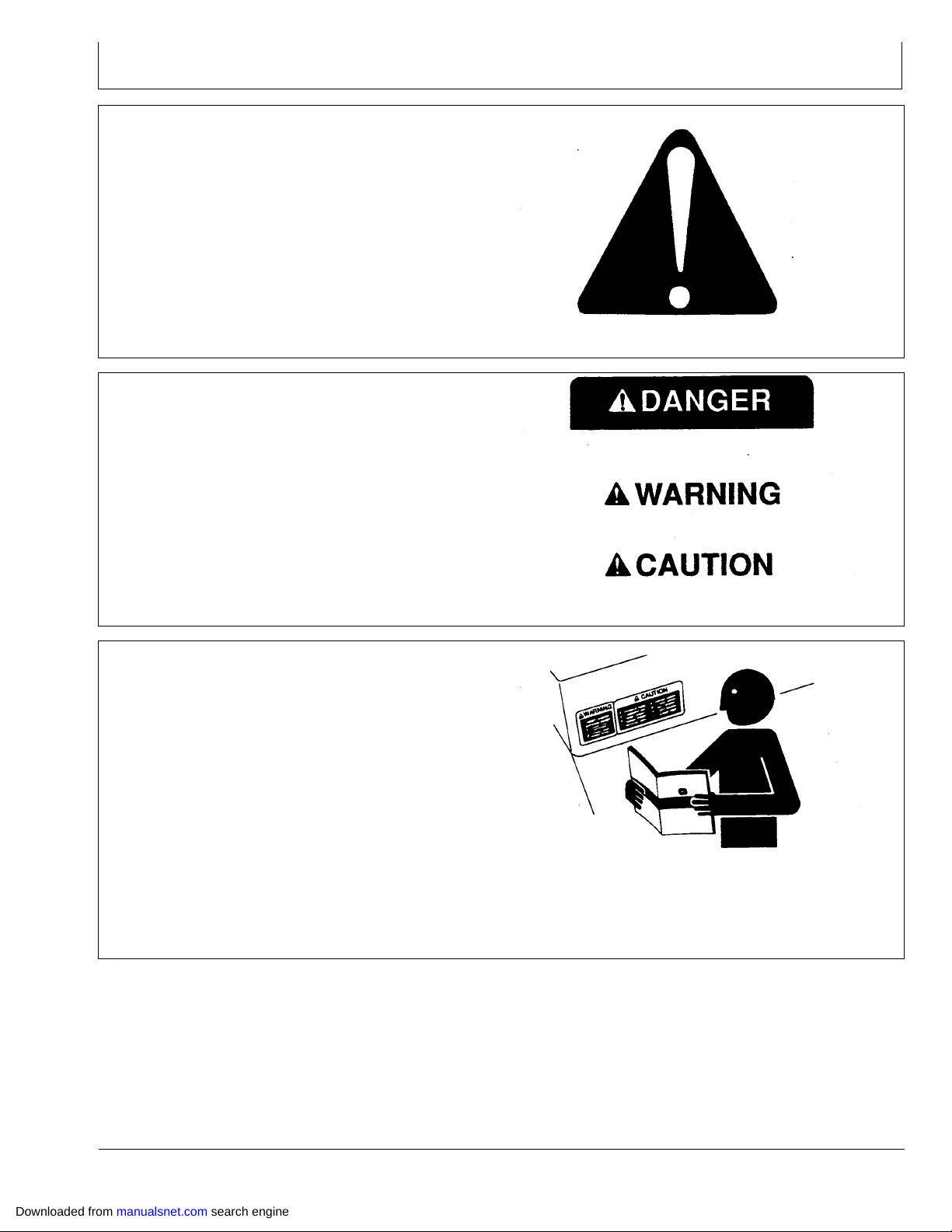
Understand Signal Words
A signal word—DANGER, WARNING, or CAUTION—is
used with the safetyalert symbol. DANGER identifies the
most serious hazards.
DANGER or WARNING safety signs are located near
specific hazards. General precautions are listed on
CAUTION safety signs. CAUTION also calls attention to
safety messages in this manual.
T81389 —UN—07DEC88
DX,ALERT 1929SEP981/1
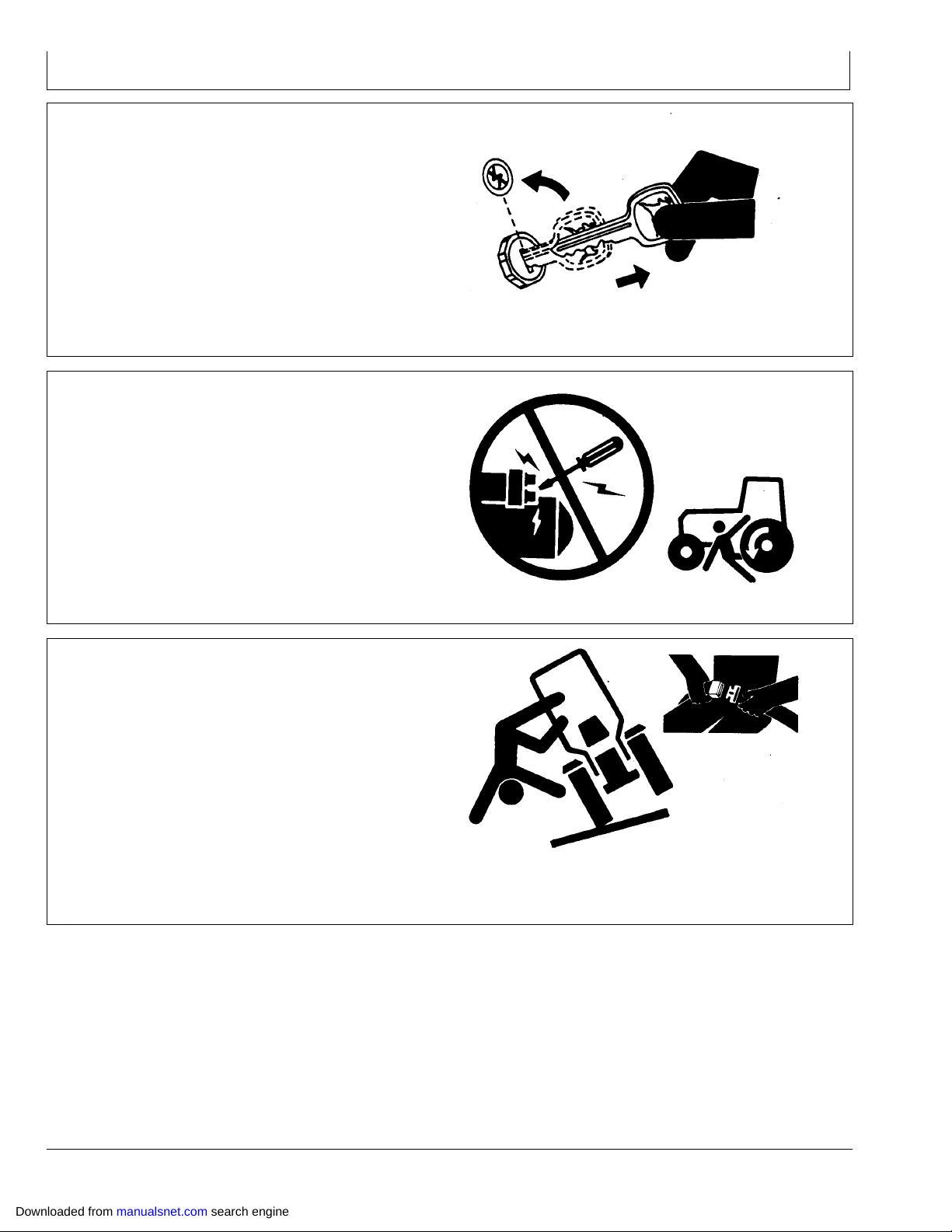
Follow Safety Instructions
Carefully read all safety messages in this manual and on
your machine safety signs. Keep safety signs in good
condition. Replace missing or damaged safety signs. Be
sure new equipment components and repair parts include
the current safety signs. Replacement safety signs are
available from your John Deere dealer.
There can be additional safety information contained on
parts and components sourced from suppliers that is not
reproduced in this operator’s manual.
Learn how to operate the machine and how to use controls
properly. Do not let anyone operate without instruction.
Keep your machine in proper working condition.
Unauthorized modifications to the machine may impair the
function and/or safety and affect machine life.
TS187 —19—30SEP88
DX,SIGNAL 1903MAR931/1
TS201 —UN—23AUG88
If you do not understand any part of this manual and need
assistance, contact your John Deere dealer.
DX,READ 1916JUN091/1
Downloaded from manualsnet.com search engine
051
122309
PN=9
Page 10
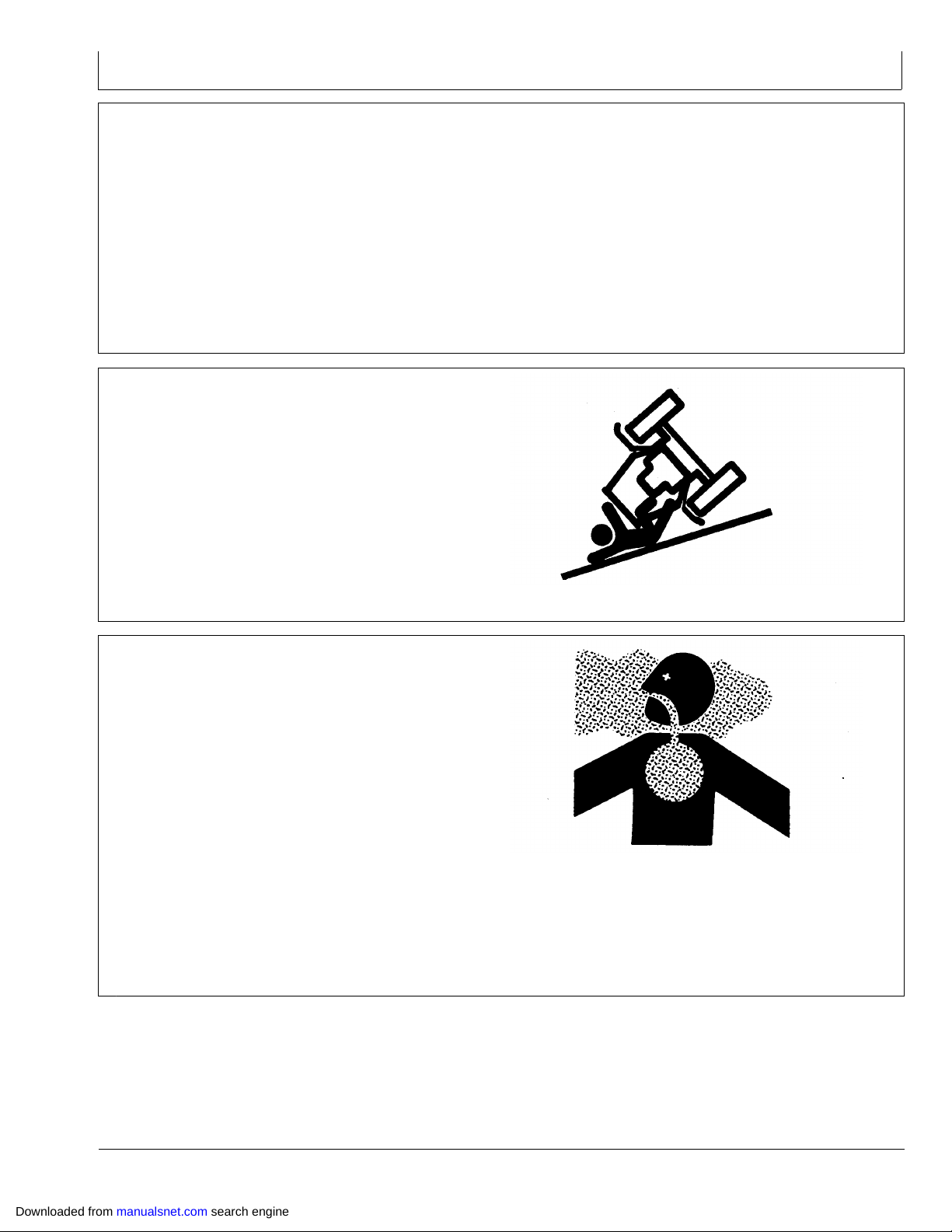
Park Machine Safely
Before working on the machine:
Lower all equipment to the ground.
•
Stop the engine and remove the key.
•
Disconnect the battery ground strap.
•
Hang a "DO NOT OPERATE" tag in operator station.
•
Prevent Machine Runaway
Avoid possible injury or death from machinery runaway.
Do not start engine by shorting across starter terminals.
Machine will start in gear if normal circuitry is bypassed.
NEVER start engine while standing on ground. Start
engine only from operator’s seat, with transmission in
neutral or park.
Safety
TS230 —UN—24MAY89
DX,PARK 1904JUN901/1
Use Seat Belt Properly
Use a seat belt when you operate with a rollover
protective structure (ROPS) or cab to minimize chance of
injury from an accident such as an overturn.
Do not use a seat belt if operating without a ROPS or cab.
Replace entire seat belt if mounting hardware, buckle,
belt, or retractor show signs of damage.
Inspect seat belt and mounting hardware at least
once a year. Look for signs of loose hardware or belt
damage, such as cuts, fraying, extreme or unusual wear,
discoloration, or abrasion. Replace only with replacement
parts approved for your machine. See your John Deere
dealer.
TS177 —UN—11JAN89
DX,BYPAS1 1929SEP981/1
TS205 —UN—23AUG88
DX,ROPS1 1929OCT071/1
Downloaded from manualsnet.com search engine
052
122309
PN=10
Page 11
Operate Safely
Safety
DO NOT start engine with multifunction control handle
engaged.
DO NOT operate close to a ditch or creek.
DO NOT fold or unfold boom near overhead wires.
Always come to a complete stop before reversing
directions.
Drive slowly over rough ground.
Slow down when turning.
Use Caution On Hillsides
Avoid holes, ditches, and obstructions which may cause
sprayer rollover, especially on hillsides. Avoid sharp
turns on hills.
Never drive near the edge of a gully or steep embankment.
Stay off slopes that are too steep for operation.
Always shut off engine when leaving machine. Remove
key when leaving machine unattended. Park brake
will engage when engine is turned off regardless of
multifunction control handle position.
Keep hands, feet and clothing away from moving parts.
Wear relatively tight and belted clothing to prevent from
being caught on some part of the machine.
OUO6092,000068F 1910AUG041/1
RW13093 —UN—07DEC88
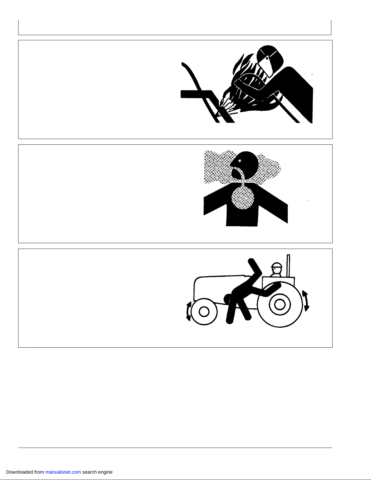
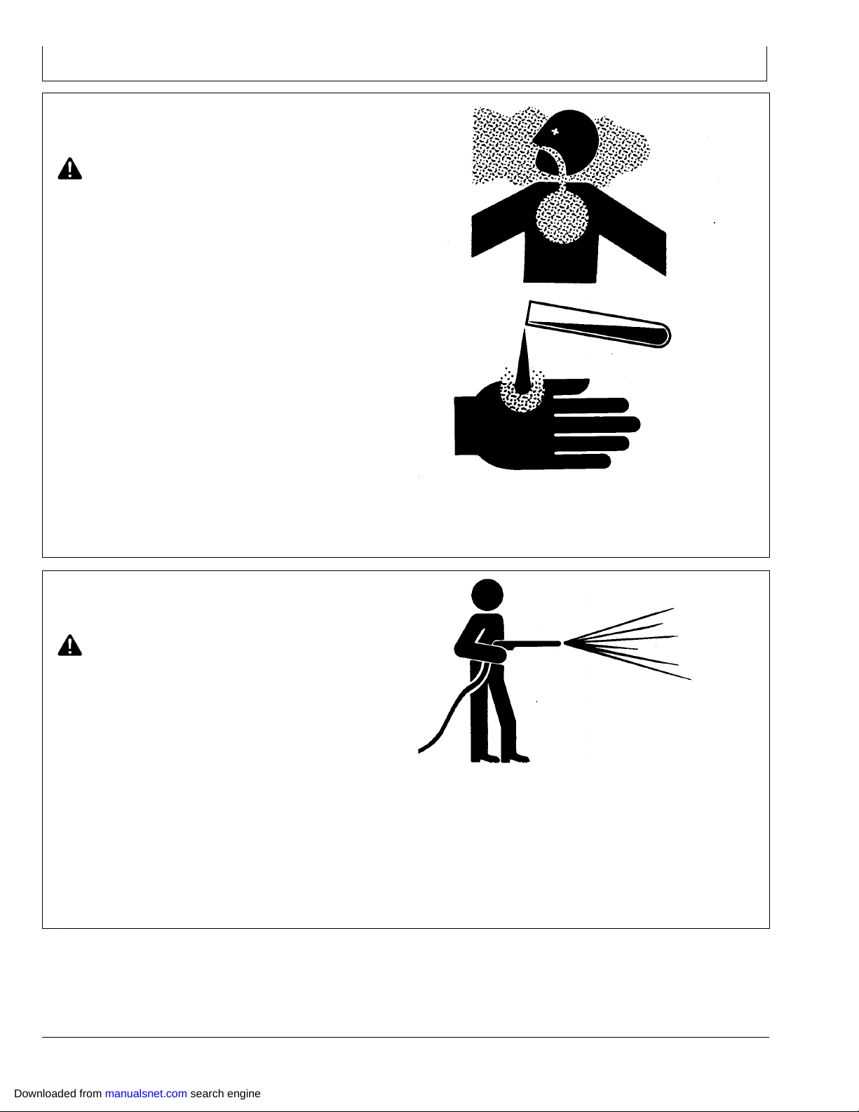
Remove Paint Before Welding or Heating
Avoid potentially toxic fumes and dust.
Hazardous fumes can be generated when paint is heated
by welding, soldering, or using a torch.
Remove paint before heating:
Remove paint a minimum of 100 mm (4 in.) from area
•
to be affected by heating. If paint cannot be removed,
wear an approved respirator before heating or welding.
If you sand or grind paint, avoid breathing the dust.
•
Wear an approved respirator.
If you use solvent or paint stripper, remove stripper with
•
soap and water before welding. Remove solvent or
paint stripper containers and other flammable material
from area. Allow fumes to disperse at least 15 minutes
before welding or heating.
Do not use a chlorinated solvent in areas where welding
will take place.
OUO6092,0000F99 1928JUN071/1
TS220 —UN—23AUG88
Do all work in an area that is well ventilated to carry toxic
fumes and dust away.
Dispose of paint and solvent properly.
DX,PAINT 1924JUL021/1
Downloaded from manualsnet.com search engine
053
122309
PN=11
Page 12
Safety
Avoid Heating Near Pressurized Fluid Lines
Flammable spray can be generated by heating near
pressurized fluid lines, resulting in severe burns to yourself
and bystanders. Do not heat by welding, soldering,
or using a torch near pressurized fluid lines or other
flammable materials. Pressurized lines can accidentally
burst when heat goes beyond the immediate flame area.
Work In Ventilated Area
Engine exhaust fumes can cause sickness or death. If
it is necessary to run an engine in an enclosed area,
remove the exhaust fumes from the area with an exhaust
pipe extension.
If you do not have an exhaust pipe extension, open the
doors and get outside air into the area.
TS953 —UN—15MAY90
DX,TORCH 1910DEC041/1
Keep Riders Off Machine
Only allow the operator on the machine. Keep riders off.
Riders on machine are subject to injury such as being
struck by foreign objects and being thrown off of the
machine. Riders also obstruct the operator’s view
resulting in the machine being operated in an unsafe
manner.
TS220 —UN—23AUG88
DX,AIR 1917FEB991/1
TS290 —UN—23AUG88
DX,RIDER 1903MAR931/1
Downloaded from manualsnet.com search engine
054
122309
PN=12
Page 13
Handle Fuel Safely—Avoid Fires
Handle fuel with care: it is highly flammable. Do not refuel
the machine while smoking or when near open flame or
sparks.
Always stop engine before refueling machine. Fill fuel
tank outdoors.
Prevent fires by keeping machine clean of accumulated
trash, grease, and debris. Always clean up spilled fuel.
Prepare for Emergencies
Be prepared if a fire starts.
Keep a first aid kit and fire extinguisher handy.
Keep emergency numbers for doctors, ambulance
service, hospital, and fire department near your telephone.
Safety
TS202 —UN—23AUG88
DX,FIRE1 1903MAR931/1
Wear Protective Clothing
Wear close fitting clothing and safety equipment
appropriate to the job.
Operating equipment safely requires the full attention of
the operator. Do not wear radio or music headphones
while operating machine.
TS291 —UN—23AUG88
DX,FIRE2 1903MAR931/1
TS206 —UN—23AUG88
DX,WEAR2 1903MAR931/1
Downloaded from manualsnet.com search engine
055
122309
PN=13
Page 14
Safety
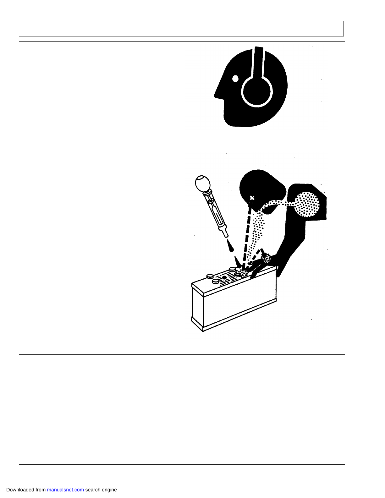
Protect Against Noise
Prolonged exposure to loud noise can cause impairment
or loss of hearing.
Wear a suitable hearing protective device such as
earmuffs or earplugs to protect against objectionable or
uncomfortable loud noises.
Prevent Acid Burns
Sulfuric acid in battery electrolyte is poisonous. It is strong
enough to burn skin, eat holes in clothing, and cause
blindness if splashed into eyes.
Avoid the hazard by:
1. Filling batteries in a wellventilated area.
2. Wearing eye protection and rubber gloves.
3. Avoiding breathing fumes when electrolyte is added.
4. Avoiding spilling or dripping electrolyte.
5. Use proper jump start procedure.
TS207 —UN—23AUG88
DX,NOISE 1903MAR931/1
If you spill acid on yourself:
1. Flush your skin with water.
2. Apply baking soda or lime to help neutralize the acid.
3. Flush your eyes with water for 15—30 minutes. Get
medical attention immediately.
If acid is swallowed:
1. Do not induce vomiting.
2. Drink large amounts of water or milk, but do not
exceed 2 L (2 quarts).
3. Get medical attention immediately.
TS203 —UN—23AUG88
DX,POISON 1921APR931/1
Downloaded from manualsnet.com search engine
056
122309
PN=14
Page 15
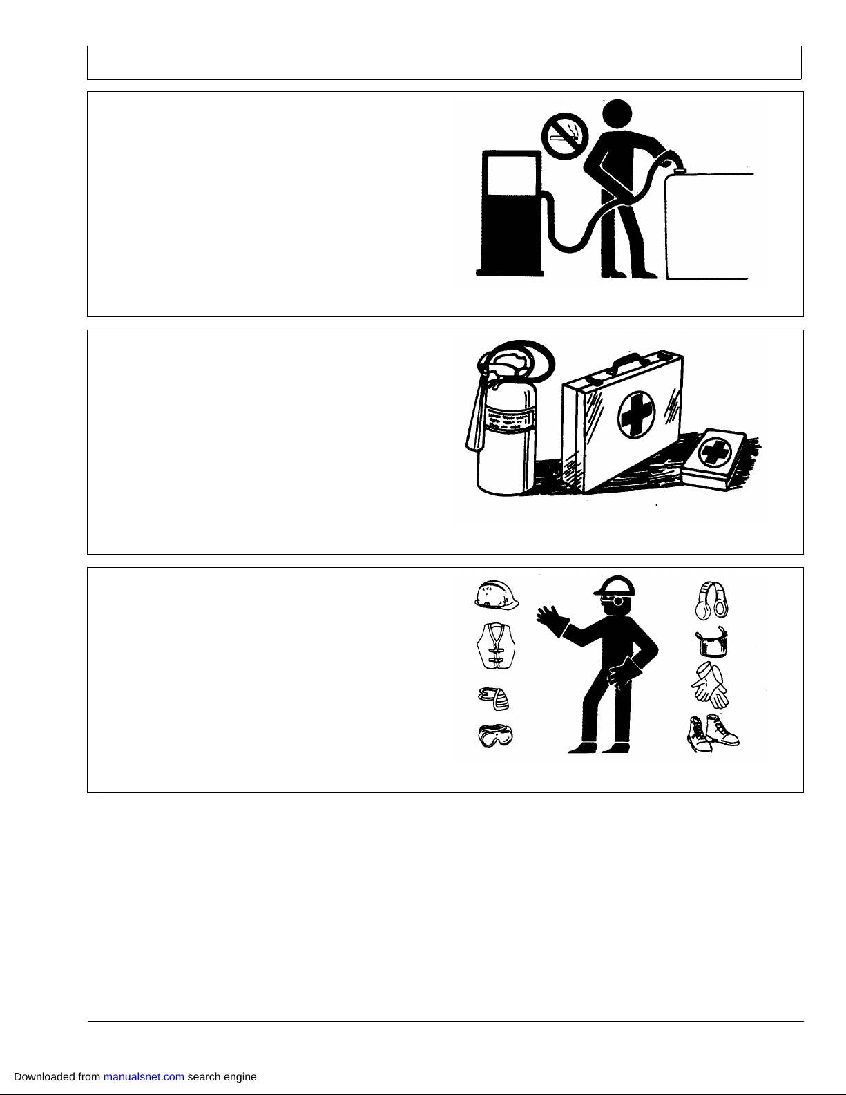
Handle Agricultural Chemicals Safely
Chemicals used in agricultural applications such
as fungicides, herbicides, insecticides, pesticides,
rodenticides, and fertilizers can be harmful to your health
or the environment if not used carefully.
Always follow all label directions for effective, safe, and
legal use of agricultural chemicals.
Reduce risk of exposure and injury:
Wear appropriate personal protective equipment as
•
recommended by the manufacturer. In the absence
of manufacturer’s instructions, follow these general
guidelines:
Chemicals labeled ’Danger’: Most toxic. Generally
require use of goggles, respirator, gloves, and skin
protection.
Chemicals labeled ’Warning’: Less toxic. Generally
require use of goggles, gloves, and skin protections.
Chemicals labeled ’Caution’: Least toxic. Generally
require use of gloves and skin protection.
Avoid inhaling spray or dusts.
•
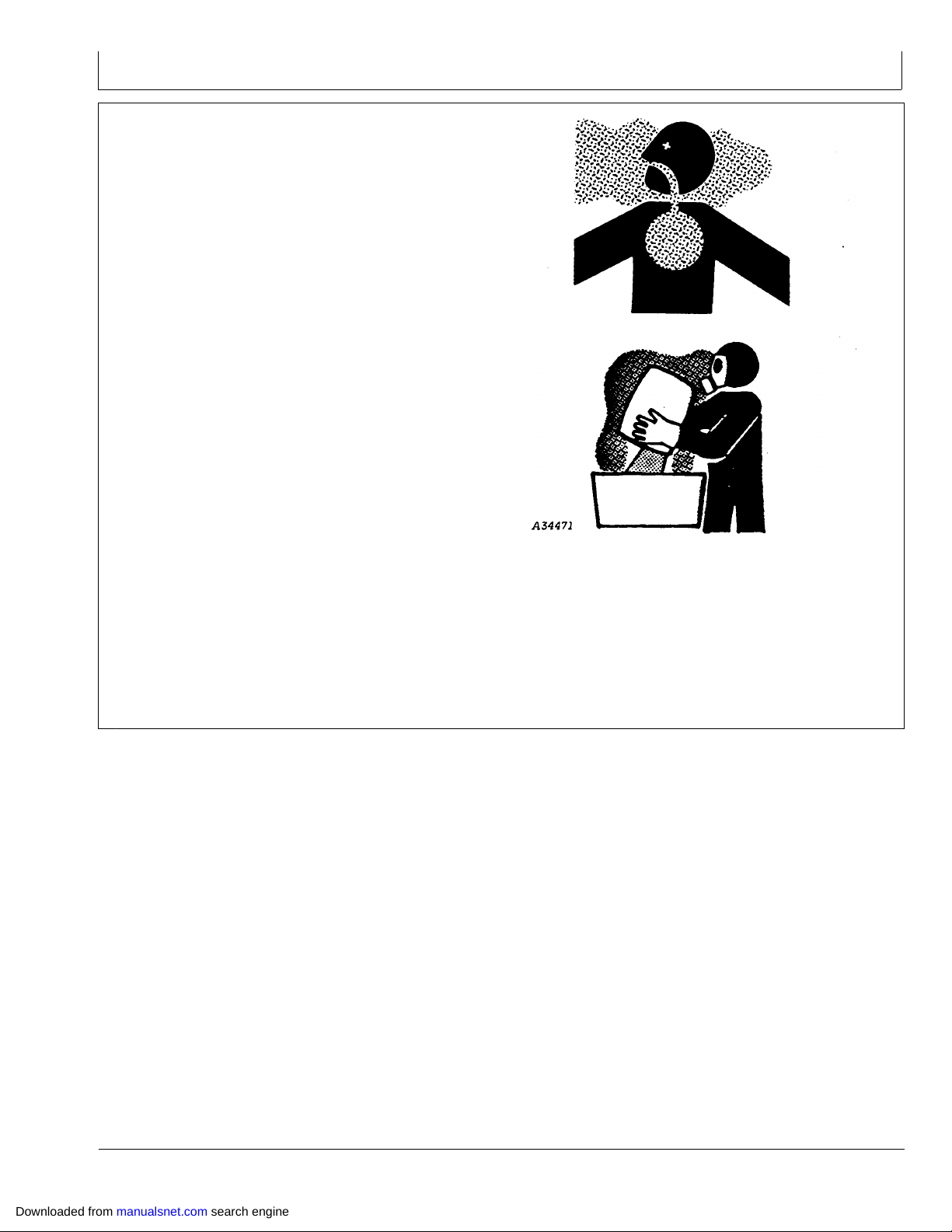
Always have soap, water, and towel available when
•
working with chemicals. If chemical contacts skin,
hands, or face, wash immediately with soap and water.
If chemical gets into eyes, flush immediately with water.
Wash hands and face after using chemicals and before
•
eating, drinking, smoking, or urination.
Do not smoke or eat while applying chemicals.
•
After handling chemicals, always bathe or shower and
•
change clothes. Wash clothing before wearing again.
Seek medical attention immediately if illness occurs
•
during or shortly after use of checmials.
Keep chemicals in original containers. Do not transfer
•
chemicals to unmarked containers or to containers used
for food or drink.
Safety
Store chemicals in a secure, locked area way from
•
human or livestock food. Keep children away.
Always dispose of containers properly. Triple rinse
•
empty containers and puncture or crush containers and
dispose of properly.
DX,WW,CHEM01 1905APR041/1
TS220 —UN—23AUG88A34471 —UN—11OCT88
Downloaded from manualsnet.com search engine
057
122309
PN=15
Page 16
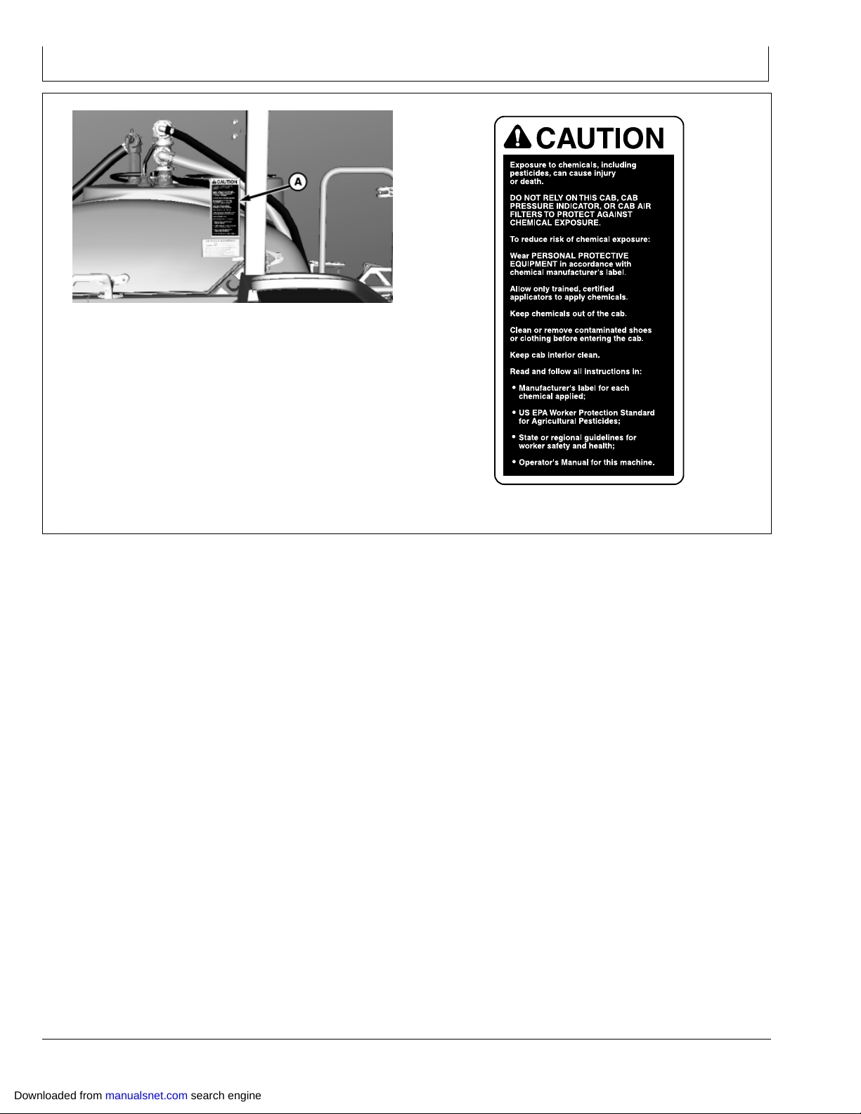
Avoid Contact with Chemicals,
Including Pesticides
CAUTION: This enclosed cab does not
protect against chemical exposure, including
exposure to pesticides.
1. When operating in an environment where harmful
chemicals are present, wear a longsleeved shirt,
longlegged pants, shoes, and socks.
Safety
2. If chemical label requires respiratory protection, wear
an appropriate respirator in the cab.
3. Wear personal protective equipment as required by
the chemical label when leaving the enclosed cab:
into a treated area,
•
to work with contaminated application equipment,
•
such as nozzles, which must be cleaned, changed,
or redirected,
to become involved with mixing and loading
•
activities.
4. Before reentering the cab, remove personal protective
equipment and store either outside the cab in a closed
box or some other type of sealable container or inside
the cab in a pesticide resistant container.
5. Clean or remove contaminated shoes or clothing
before entering the cab.
Clean Vehicle of Hazardous Chemicals, Including Pesticides
CAUTION: During application of hazardous
chemicals, including pesticides, residue
can build up on the inside or outside of
the vehicle. Clean vehicle according to use
instructions of hazardous chemical.
TS220 —UN—23AUG88TS272 —UN—23AUG88
OUO6092,0000337 1904MAR021/1
When exposed to hazardous chemicals, clean exterior and
interior of vehicle daily to keep free of the accumulation of
visible dirt and contamination.
1. Sweep or vacuum the floor of cab.
2. Clean headliners and inside cowlings of cab.
IMPORTANT: Directing pressurized water at
electronic/electrical components or connectors,
bearings and hydraulic seals, fuel injection
pumps or other sensitive parts and components
may cause product malfunctions. Reduce
pressure, and spray at a 45 to 90 degree angle.
Downloaded from manualsnet.com search engine
3. Wash entire exterior of vehicle.
4. Dispose of any wash water with hazardous
concentrations of active or nonactive ingredients
according to published regulations or directives.
058
T6642EJ —UN—18OCT88
OUO6092,000081B 1923JUN051/1
122309
PN=16
Page 17
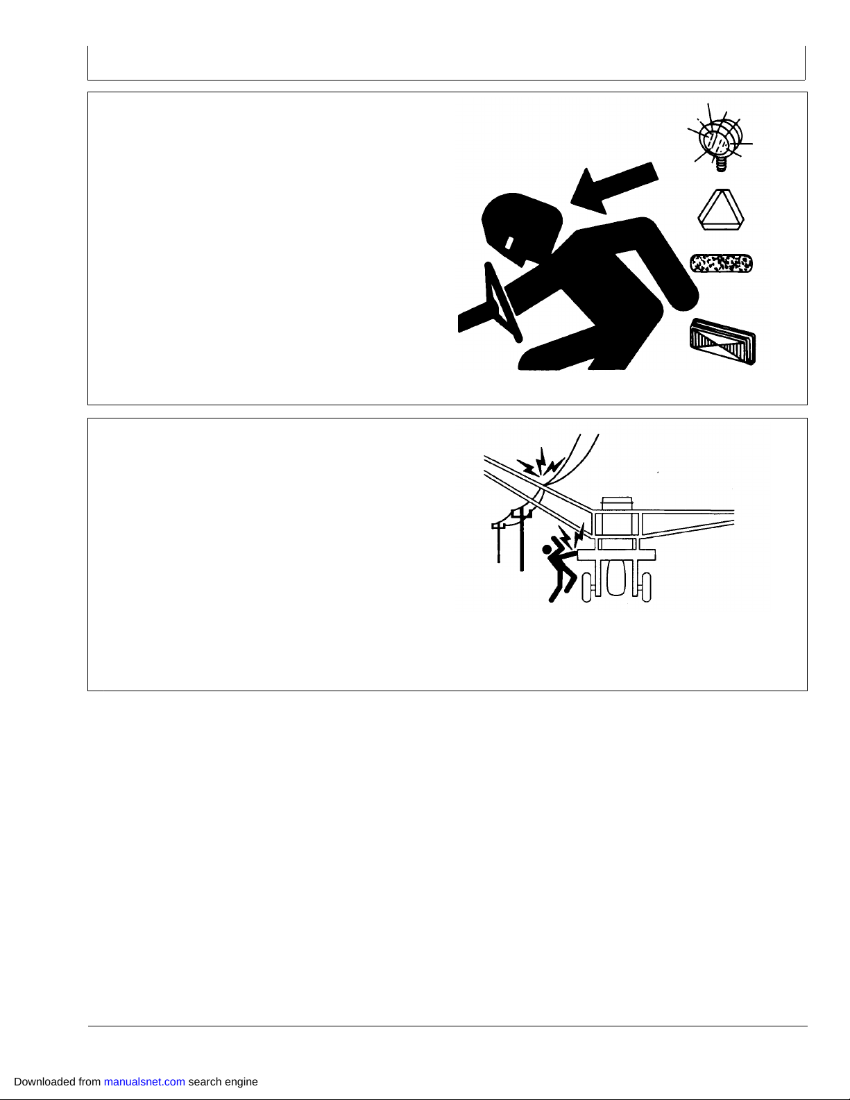
Use Safety Lights and Devices
Prevent collisions between other road users, slow moving
tractors with attachments or towed equipment, and
selfpropelled machines on public roads. Frequently
check for traffic from the rear, especially in turns, and use
turn signal lights.
Use headlights, flashing warning lights, and turn signals
day and night. Follow local regulations for equipment
lighting and marking. Keep lighting and marking visible,
clean, and in good working order. Replace or repair
lighting and marking that has been damaged or lost. An
implement safety lighting kit is available from your John
Deere dealer.
Transport and Operate Safely
Keep away from overhead power lines. Serious injury
or death to you or others can result should machine
contact electrical wires. Know the transport height, boom
operating height and boom folding height of your machine.
Safety
TS951 —UN—12APR90
DX,FLASH 1907JUL991/1
Stop slowly to avoid “nose diving”.
Keep SMV emblem and reflectors clean and in place.
Do not exceed maximum transport speed specified in the
operator manual.
Reduce speeds for icy, wet, graveled or soft roadway
surfaces.
Check and follow local regulations for equipment size,
lighting and marking before driving on public roadways.
N44191 —UN—27APR92
OUO6092,00002ED 1923DEC091/1
Downloaded from manualsnet.com search engine
059
122309
PN=17
Page 18
Safety
Practice Safe Maintenance
Understand service procedure before doing work. Keep
area clean and dry.
Never lubricate, service, or adjust machine while it is
moving. Keep hands, feet , and clothing from powerdriven
parts. Disengage all power and operate controls to relieve
pressure. Lower equipment to the ground. Stop the
engine. Remove the key. Allow machine to cool.
Securely support any machine elements that must be
raised for service work.
Keep all parts in good condition and properly installed.
Fix damage immediately. Replace worn or broken parts.
Remove any buildup of grease, oil, or debris.
On selfpropelled equipment, disconnect battery ground
cable () before making adjustments on electrical systems
or welding on machine.
On towed implements, disconnect wiring harnesses from
tractor before servicing electrical system components or
welding on machine.
Using Compressed Air For Cleaning
CAUTION: Reduce compressed air to 210 kPa
(2 bar) (30 psi) or less when using for cleaning
purposes. Clear area of bystanders, guard
against flying debris, and wear personnel
protective equipment, including eye protection.
TS218 —UN—23AUG88
DX,SERV 1917FEB991/1
TS266 —UN—23AUG88
AG,OUO6043,83 1928JUL991/1
Downloaded from manualsnet.com search engine
0510
122309
PN=18
Page 19
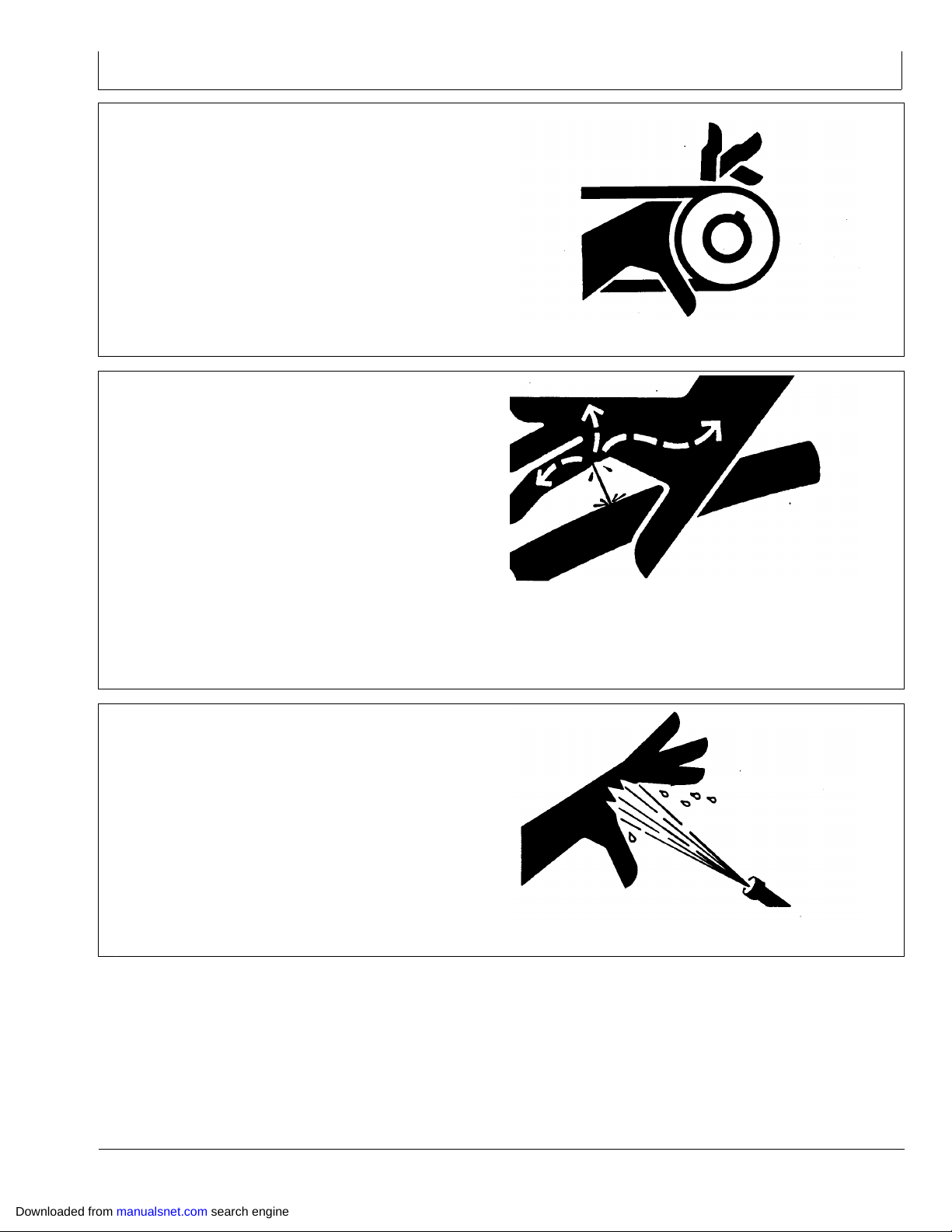
Service Drive Belts Safely
When servicing drive belts always observe these
precautions:
Avoid serious injury from hand or arm entanglement.
•
Never attempt to clean, check or adjust belts while the
machine is running. Always shut off the engine, set the
parking brake and remove the key.
Do not attempt to clean belts with flammable cleaning
•
solvents.
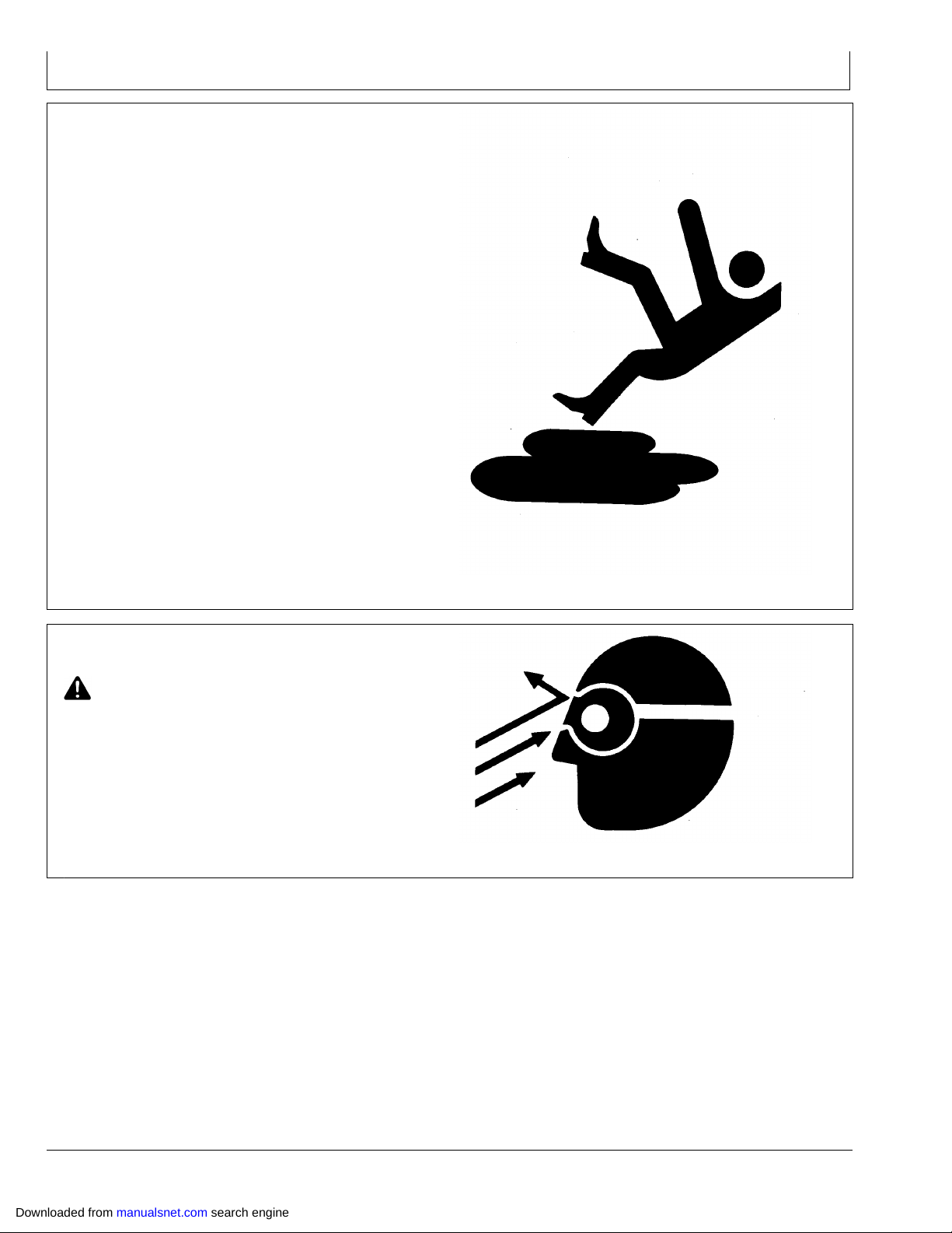
Avoid HighPressure Fluids
Escaping fluid under pressure can penetrate the skin
causing serious injury.
Avoid the hazard by relieving pressure before
disconnecting hydraulic or other lines. Tighten all
connections before applying pressure.
Search for leaks with a piece of cardboard. Protect hands
and body from highpressure fluids.
Safety
TS285 —UN—23AUG88
OUO6043,00015E3 1924MAY041/1
If an accident occurs, see a doctor immediately. Any fluid
injected into the skin must be surgically removed within
a few hours or gangrene may result. Doctors unfamiliar
with this type of injury should reference a knowledgeable
medical source. Such information is available from Deere
& Company Medical Department in Moline, Illinois, U.S.A.,
by calling 18008228262 or +1 3097485636.
Do Not Open HighPressure Fuel System
Highpressure fluid remaining in fuel lines can cause
serious injury. Do not disconnect or attempt repair of fuel
lines, sensors, or any other components between the
highpressure fuel pump and nozzles on engines with
High Pressure Common Rail (HPCR) fuel system.
Only technicians familiar with this type of system can
perform repairs. (See your John Deere dealer.)
X9811 —UN—23AUG88
DX,FLUID,NA 1929JUL091/1
TS1343 —UN—18MAR92
DX,WW,HPCR1 1907JAN031/1
Downloaded from manualsnet.com search engine
0511
122309
PN=19
Page 20
Check Hydraulic Hoses
Hydraulic hoses can fail due to physical damage, kinks,
age, and exposure. Check hoses regularly. Replace
damaged hoses.
Escaping fluid under pressure can penetrate the skin
causing serious injury to you or others. Search for leaks
with a piece of cardboard. Protect hands and body from
high pressure fluids.
If an accident occurs see a doctor immediately. Any fluid
injected into the skin must be surgically removed within
a few hours or gangrene can result. Doctors unfamiliar
with this type of injury should reference a knowledgeable
medical source. Such information is available from Deere
and Company Medical Department in Moline, Illinois,
U.S.A.
Service Cooling System Safely
Explosive release of fluids from pressurized cooling
system can cause serious burns.
Shut off engine. Only remove filler cap when cool enough
to touch with bare hands. Slowly loosen cap to relieve
pressure before removing completely.
Safety
X9811 —UN—23AUG88
NXN,9930,HYD 1902DEC971/1
Add coolant only when engine is shut off.
Service Accumulator Systems Safely
Escaping fluid or gas from pressurized hydraulic
accumulator systems can cause serious injury. Extreme
heat can cause the accumulator to burst, and pressurized
lines can be accidentally cut. Do not weld or use a torch
near a pressurized accumulator or pressurized line.
Relieve pressure from the hydraulic system before
removing accumulator. Never attempt to relieve hydraulic
system or accumulator pressure by loosening a fitting.
Accumulators cannot be repaired.
TS281 —UN—23AUG88
OUO6092,000026F 1913OCT091/1
TS281 —UN—23AUG88
DX,WW,ACCLA 1915APR031/1
Downloaded from manualsnet.com search engine
0512
122309
PN=20
Page 21
Service Tires Safely
CAUTION: Explosive separation of a tire and rim
parts can cause serious injury or death.
Do not attempt to mount a tire unless you
have the proper equipment and experience
to perform the job.
Always maintain the correct tire pressure. Do not inflate
the tires above the recommended pressure.
Never weld or heat a wheel and tire assembly. The heat
can cause an increase in air pressure resulting in a tire
explosion. Welding can structurally weaken or deform
the wheel.
When inflating tires, use a clipon chuck and extension
hose long enough to allow you to stand to one side and
NOT in front of or over the tire assembly. Use a safety
cage if available.
Check wheels for low pressure, cuts, bubbles, damaged
rims or missing lug bolts and nuts.
Safety
Handle Global Positioning Receivers and Brackets Safely
Falling while installing or removing a global positioning
receiver can cause serious injury. Use a ladder or platform
to easily reach a mounting location.
Use sturdy and secure footholds and handholds. Do not
install or remove the receiver in wet or icy conditions.
The receiver mast used on implements is heavy and can
be awkward to handle. Two people are required when
mounting locations are not accessible from the ground or
from a service platform. Use proper lifting techniques and
wear proper protective equipment.
TS211 —UN—23AUG88
DX,RIM1 1927OCT081/1
TS249 —UN—23AUG88
DX,WW,RECEIVER 1908JAN081/1
Downloaded from manualsnet.com search engine
0513
122309
PN=21
Page 22
Safety
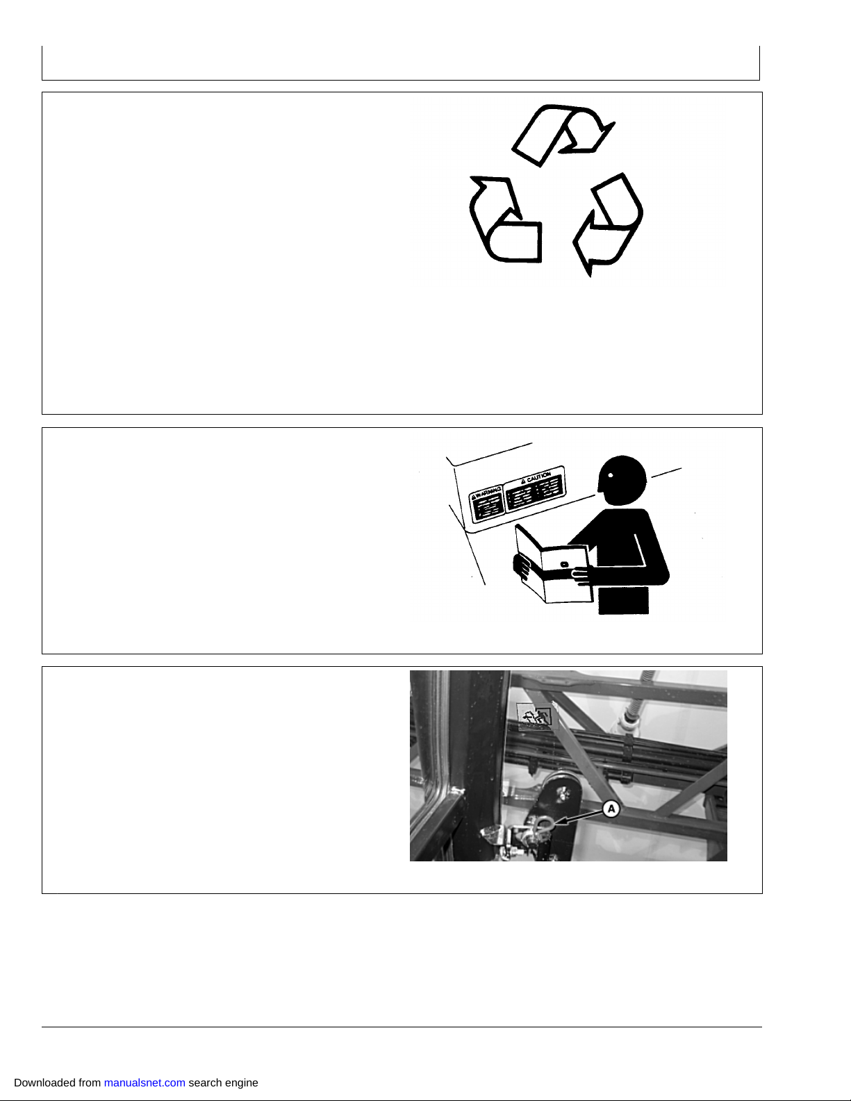
Dispose of Waste Properly
Improperly disposing of waste can threaten the
environment and ecology. Potentially harmful waste used
with John Deere equipment include such items as oil, fuel,
coolant, brake fluid, filters, and batteries.
Use leakproof containers when draining fluids. Do not use
food or beverage containers that may mislead someone
into drinking from them.
Do not pour waste onto the ground, down a drain, or into
any water source.
Air conditioning refrigerants escaping into the air can
damage the Earth’s atmosphere. Government regulations
may require a certified air conditioning service center to
recover and recycle used air conditioning refrigerants.
Inquire on the proper way to recycle or dispose of waste
from your local environmental or recycling center, or from
your John Deere dealer.
Replace Safety Signs
Replace missing or damaged safety signs. See the
machine operator’s manual for correct safety sign
placement.
TS1133 —UN—26NOV90
DX,DRAIN 1903MAR931/1
Emergency Exit
Remove pin (A). The window can now be pushed out of
retaining clips and allowed to fall free.
(See your John Deere dealer for window replacement.)
A—Pin
TS201 —UN—23AUG88
DX,SIGNS1 1904JUN901/1
N84876 —UN—04JUN09
OUO6092,0000101 1908JUL091/1
Downloaded from manualsnet.com search engine
0514
122309
PN=22
Page 23

Safety
Empty Tank and Boom
Plumbing—Decontaminate Spray Equipment
CAUTION: Empty tank. When removing hoses,
be aware of residual spray material that
needs to be drained carefully.
Decontaminate work area before servicing.
Decontamination should be done in a safe area
by washing with water or neutralizing agent,
or by means recommended by manufacturer
of chemical last used.
Spray solutions or vapors may be extremely
dangerous. Treat all spray chemicals, solutions,
or solution residues with great caution. DO
NOT take chances. When in doubt, proceed
as though contamination is present.
Keep spray material from contacting skin.
If spray material contacts skin, wash off
immediately with clean water and detergent
or follow manufacturer’s instructions for
chemical last used.
KB78086,000051A 1907MAY081/1
Downloaded from manualsnet.com search engine
0515
122309
PN=23
Page 24
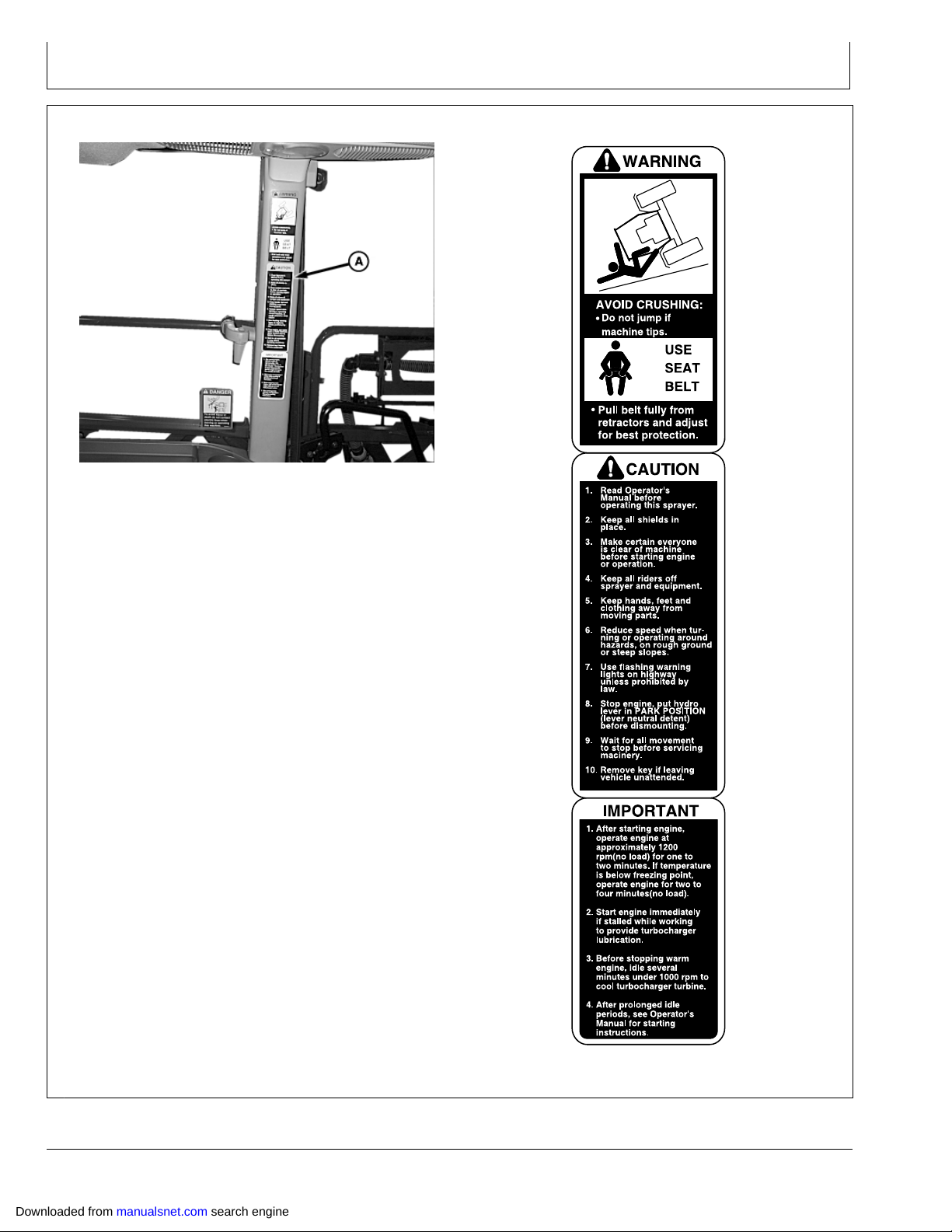
Safety Signs
Safety Signs
N83546 —UN—11MAR09
Downloaded from manualsnet.com search engine
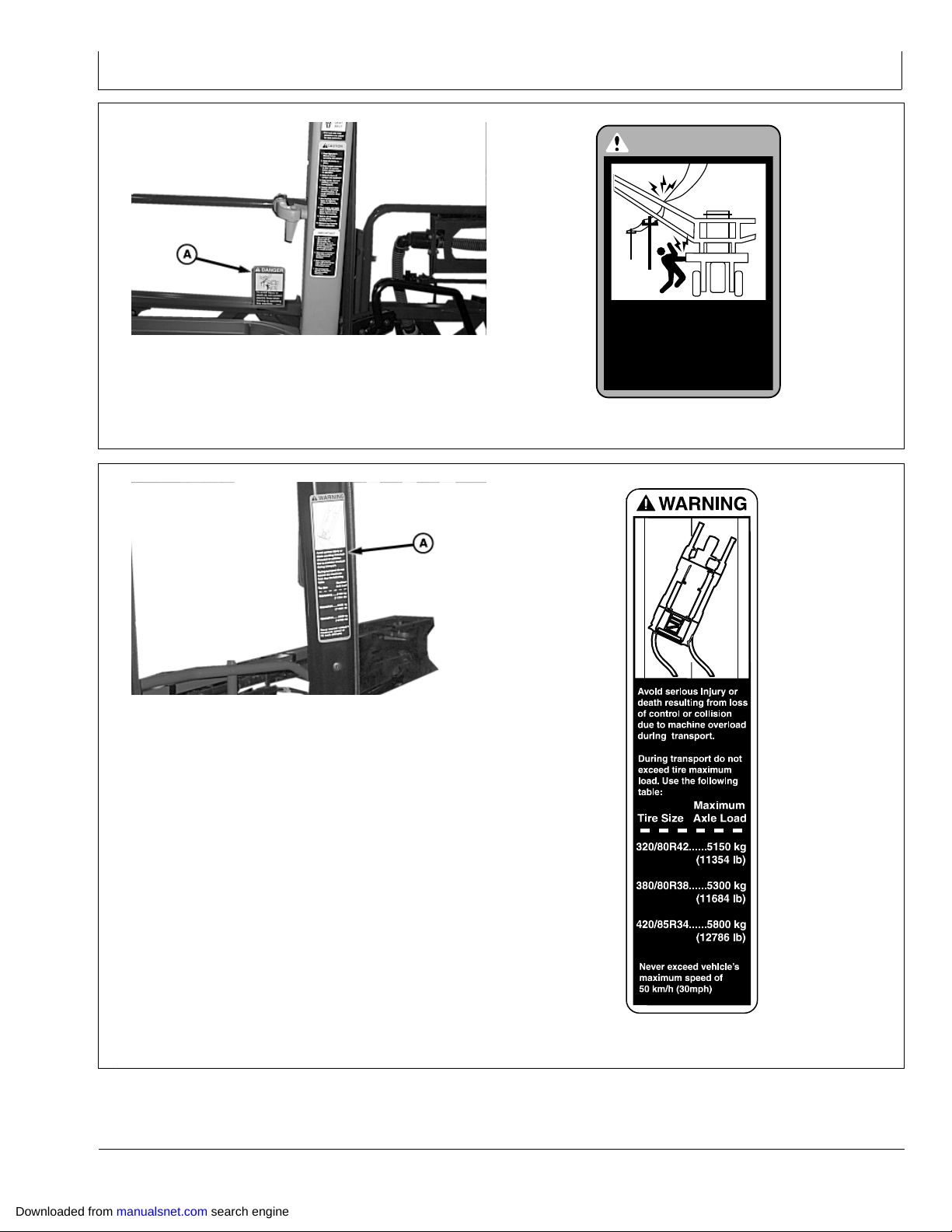
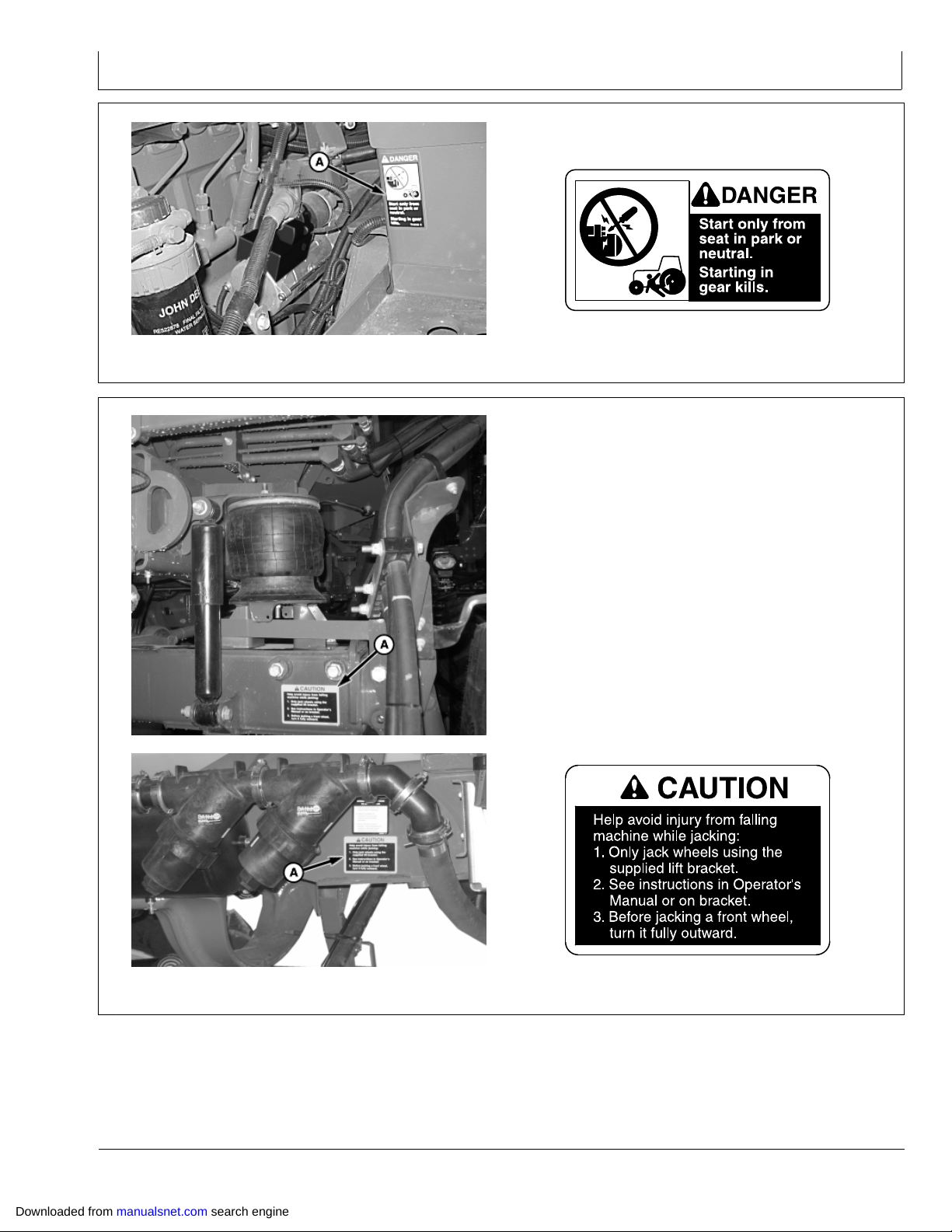
Decal A
Continued on next page OUO6092,00000E1 1911MAY091/13
101
SSN204681 —19—09AUG05
122309
PN=24
Page 25
Safety Signs
To avoid injury or
death do not contact
electric lines when
moving or operating
this machine.
DANGER
N83547 —UN—11MAR09
SSN204628 —19—08JUL05
Decal A
OUO6092,00000E1 1911MAY092/13
Transport Decal
Downloaded from manualsnet.com search engine
N83548 —UN—11MAR09
Decal A
Continued on next page OUO6092,00000E1 1911MAY093/13
102
SSN317099 —19—15JUL09
122309
PN=25
Page 26
Safety Signs
N81649 —UN—22SEP08
SSN303688 —19—09AUG05
Decal A
Continued on next page OUO6092,00000E1 1911MAY094/13
Downloaded from manualsnet.com search engine
103
122309
PN=26
Page 27
Safety Signs
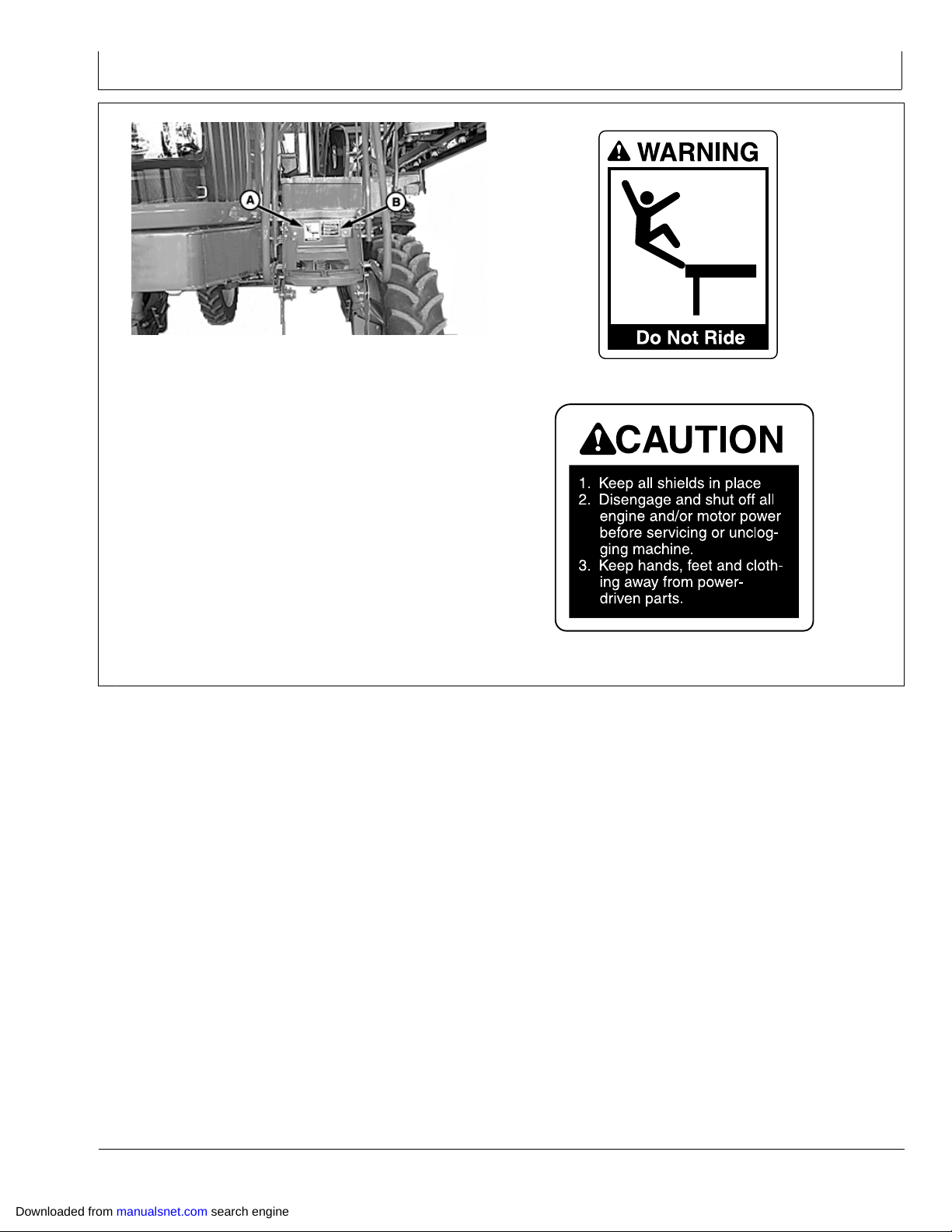
N81654 —UN—22SEP08
SSN272929 —19—09AUG05
Decal A
SSN82510 —19—09AUG05
Decal B
Continued on next page OUO6092,00000E1 1911MAY095/13
Downloaded from manualsnet.com search engine
104
122309
PN=27
Page 28
Safety Signs
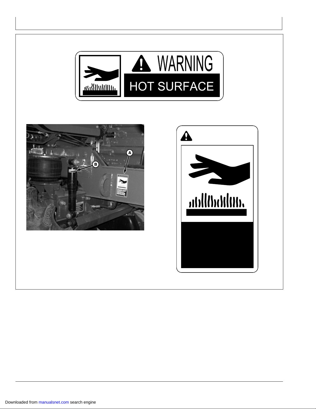
WARNING
Exhaust system components
can reach 700˚ F. To avoid
severe burns, do not
contact exhaust manifold,
turbocharger components,
muffler, or exhaust pipes.
Decal B
SSM117554 —19—27MAR09
N84206 —UN—17APR09
Decal A
Continued on next page OUO6092,00000E1 1911MAY096/13
105
SSN203310 —19—09AUG05
122309
PN=28
Downloaded from manualsnet.com search engine
Page 29
Safety Signs
N83549 —UN—14APR09
N83815 —UN—23MAR09N81657 —UN—22SEP08
SST146102 —19—09AUG05
Decal A
OUO6092,00000E1 1911MAY097/13
Downloaded from manualsnet.com search engine
Decal A
Continued on next page OUO6092,00000E1 1911MAY098/13
106
SSN209455 —19—09AUG05
122309
PN=29
Page 30
Safety Signs
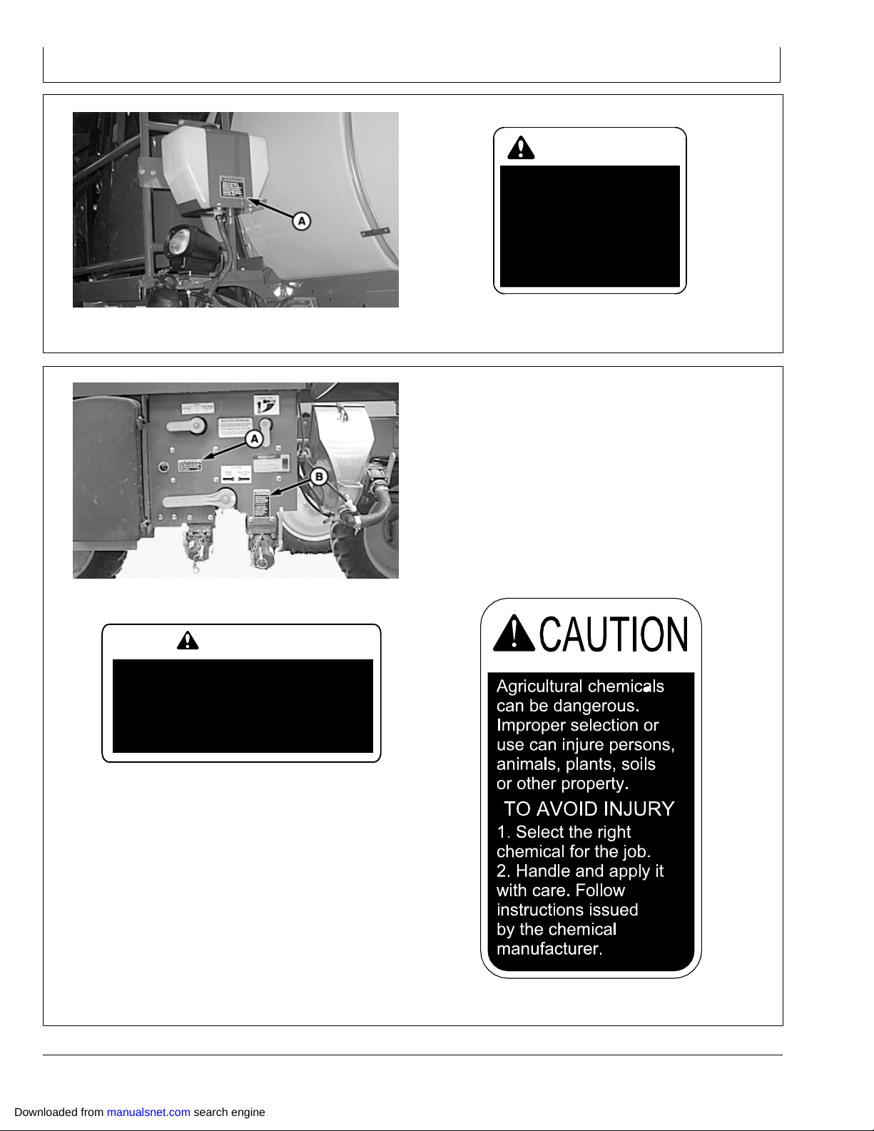
WARNING
Water for rinse/wash
purpose only. Do not
drink from this container.
Container may become
contaminated by sprayer
chemicals. Fill with clean
rinse water only.
CAUTION
Avoid injury from impact with sprayer
frame. Chassis moves during inflation
and deflation of air bag suspension
system. Stand clear of machine when
operating system.
N81652 —UN—05JUN09
N81651 —UN—25NOV08
SSN302108 —19—09AUG05
Decal A
OUO6092,00000E1 1911MAY099/13
Decal A
Downloaded from manualsnet.com search engine
SSN307233 —19—14JUL05
Decal B
Continued on next page OUO6092,00000E1 1911MAY0910/13
107
SSN203265 —19—04NOV09
122309
PN=30
Page 31

Safety Signs
DANGER
N83814 —UN—26JUN09
SSN209177 —19—09AUG05
Decal A
OUO6092,00000E1 1911MAY0911/13
Decal A
N81659 —UN—22SEP08
Continued on next page OUO6092,00000E1 1911MAY0912/13
108
SSE82514 —19—25JUL05
122309
PN=31
Downloaded from manualsnet.com search engine
Page 32

Safety Signs
N83550 —UN—11MAR09
Decal A
SSN302717 —19—09AUG05
OUO6092,00000E1 1911MAY0913/13
Downloaded from manualsnet.com search engine
109
122309
PN=32
Page 33

Safety Signs
Downloaded from manualsnet.com search engine
1010
122309
PN=33
Page 34

Safety Features
L
A
A
I
K
H
J
G
F
B
M
N
O
C
E
D
Safety Features
A—FRONT AND REAR HAZARD
LIGHTS—Alerts oncoming
and following traffic of your
presence on roads.
B—HOSES ON TOP OF
TANK—Helps prevent tank
drainage if a hose breaks.
C—SMV EMBLEM—Alerts
following traffic of your
presence on roads.
D—REFLECTORS ON
BOOM—Alerts following
traffic of your presence on
roads.
E—SLIP RESISTANT
SURFACES—Helps prevent
slippage when walking on
platform.
F— CLEAN WATER
TANK—Provides a supply
of clean water for infield
cleaning and emergency
situations when working with
chemicals.
G—GROUND LEVEL
FILLING—Allows operator to
add chemicals at ground level
which helps prevent spilling
or splattering.
H—DIVOTTED STEPS AND
PLATFORMS—Helps prevent
slipping when on platform or
ladders, also diminishes dirt
and mud build up.
In addition to the safety features described here, other
components and systems, safety signs on the machine,
safety messages in the Operator’s Manual and elsewhere,
I— HAND RAILS—Gives support
when climbing onto machine
or walking on platforms.
J— STARTER SOLENOID
SHIELDING—For bypass
start prevention.
K—FAN GUARDING—Protection
from Engine Fan.
L— EMERGENCY EXIT—Exit from
right side of cab if required.
M—TRACTOR STYLE CAB WITH
SEAT BELT— For operator
comfort.
N—LARGE REARVIEW
MIRRORS AND WINDSHIELD
WIPER—For clear view of
surroundings.
O—AUTOMATIC PARK—Shifts
automatically into park when
machine stops.
as well as the care and concern of a capable operator,
contribute to the safety of operators and others nearby.
OUO6092,0000130 1929APR091/1
N82359 —UN—29APR09
Downloaded from manualsnet.com search engine
151
122309
PN=34
Page 35

Front Console
Operators Station
A—Stop Warning Light
B—Engine Preheating
Indicator
C—Caution Indicator Light
D—Windshield Wiper Switch
E—Light Switch
F— Low Beam And High Beam
Switch
G—Hazard Warning Light
Switch
H—Turn Signal Switch
I— Horn
J— Steering Wheel Tilt Release
K—Key Switch
L— Brake Pedal
M—Boom Fold Mode Switch
N—Steering Wheel Telescoping
Release
N81790 —UN—03NOV08N83816 —UN—23MAR09N81792 —UN—04MAY09
Downloaded from manualsnet.com search engine
201
OUO6092,0000102 1915APR091/1
122309
PN=35
Page 36

Key Switch
CAUTION: Sound horn before starting engine to
clear people away from the machine.
To avoid the possibility of personnel injury
or death, start ONLY from the operator seat.
Do not start engine by shorting across
starter terminals. Machine will start in gear
if normal circuit is bypassed.
Operators Station
Key switch (A) is located on the righthand side of the
steering column and has four positions:
Accessory position (top of key turned counterclockwise
•
from Off position) allows accessories such as radio and
windshield wiper to operate.
Off position (B) shuts off engine and all accessory
•
functions.
Accessory/Run position (top of key turned clockwise
•
from Off position to first detent) allows all accessories to
operate and engine to run once it has been started.
Start position (top of key turned clockwise from Off
•
position past the detent position and held there) is a
Adjust Steering Wheel
Telescope
Rotate knob (A) counterclockwise to release lock. Extend
or retract steering wheel to desired position. Rotate knob
clockwise to lock.
Tilt
Pull up on lever (B) and move the steering column to the
desired position. Release lever to lock.
A—Knob B—Lever
A—Accessories Position
B—Off Position
momentary switch position that cranks the engine.
Once the engine starts and the switch is released, it
will return to accessory/run position. (See Starting The
Engine in this section for important details on starting
your machine.)
OUO6092,0000103 1927OCT081/1
N81793 —UN—23MAR09
Downloaded from manualsnet.com search engine
202
N83817 —UN—31MAR09
OUO6092,00001A9 1925MAR091/1
122309
PN=36
Page 37

Operators Station
Operate Turn Signals
Turn lever (A) right for a right turn, or left for a left turn.
Return lever to center position after completing turn.
A—Turn signal lever
Operate the Hazard Warning Light Switch
Push top of switch (A) to activate warning lights.
Turn signals operate as hazard lights regardless of key
position.
NOTE: Always turn hazard lights off when spraying.
A—Hazard warning light switch
N82178 —UN—03NOV08
OUO6092,0000106 1928OCT081/1
Operate Windshield Wiper
Rotate knob (A) to operate wiper at desired speed:
Off
•
Slow
•
Fast
•
A—Knob
N82180 —UN—03NOV08
OUO6092,0000107 1928OCT081/1
N82344 —UN—13NOV08
OUO6092,0000110 1908JUL091/1
Downloaded from manualsnet.com search engine
203
122309
PN=37
Page 38

Operators Station
Operate Horn
Press switch (A) to sound the horn.
A—Horn switch
Operate Light Switch and High/Low Beam Switch
CAUTION: Accidental collision with another
vehicle can cause serious injury or death to you
or others. Always comply with traffic regulations
when driving machine on a road. Dim headlights
to lowbeam for oncoming vehicles.
To avoid motorist confusion, do not operate work
lights when transporting on public roadways.
N82179 —UN—23MAR09
OUO6092,0000105 1925MAR091/1
Light switch (F) has five positions—OFF (B), Road (C),
Field 1 (D), Field 2 (E), Exit Lighting (G) and operates
regardless of the key position.
Off Position
Turns off all exterior lighting with exception of warning
lights if hazard light switch is on.
Exit Lighting
Exit lighting is activated by turning the light switch counter
clockwise
Each time the exit lighting position (G) is activated on
the light switch the cab roof lights and fill station light will
turn on for 30 seconds. The operator can bump the exit
lighting switch up to three times. Each bump increases the
time that the lights stay on by 30 seconds for a maximum
time of 90 seconds.
High/Low Beam
A—High/Low Beam Switch
B—OFF Position
C—Road Position
D—Field Position 1
E—Field Position 2
F— Light Switch
G—Exit Lighting
Push upper portion of switch (A) forward to activate high
beam head lights. Push lower portion of switch forward
to operate low beam.
Dim headlights for oncoming vehicles. Adjust headlights
correctly. (See Aiming Headlights in the Electrical System
Service section.)
NOTE: (See Light Operation Table in this section.)
OUO6092,0000109 1908JUL091/1
N83818 —UN—31MAR09
Downloaded from manualsnet.com search engine
204
122309
PN=38
Page 39

Light Operation Table
E
B
H
A
C
G
D
F
Operators Station
N82196 —UN—06NOV08
A—Hood / Grill Work Lights
B—High / Low Beams
ROAD LIGHT SWITCH
OFF LOW OFF OFF OFF OFF OFF OFF
OFF HIGH OFF OFF OFF OFF OFF OFF
ROAD LOW ON OFF OFF OFF OFF OFF
ROAD HIGH OFF ON OFF OFF OFF OFF
FIELD 1
FIELD 1
FIELD 2
FIELD 2
DELAY
DELAY
ROAD LIGHT SWITCH WARN SWITCH TURN SIGNAL REAR TAIL (RED)
OFF OFF OFF OFF OFF
OFF OFF ON OFF ON T
OFF ON OFF OFF ON W
OFF ON ON OFF ON T
ROAD OFF OFF ON ON W
ROAD OFF ON ON ON T
ROAD ON OFF ON ON W
ROAD ON ON ON ON T
FIELD 1
FIELD 1
FIELD 1
FIELD 1
FIELD 2
FIELD 2
FIELD 2
FIELD 2
DELAY
DELAY
C—Front Caution (Yellow)
D—Roof Floods
HIGH / LOW
SWITCH
LOW ON OFF OFF OFF ON ON
HIGH OFF ON OFF OFF ON ON
LOW ON OFF ON ON ON ON
HIGH OFF ON ON ON ON ON
LOW OFF OFF ON ON OFF OFF
HIGH OFF OFF ON ON OFF OFF
LOW BEAM HIGH BEAM
OFF OFF OFF OFF
OFF ON OFF ON T
ON OFF OFF ON W
ON ON OFF ON T
OFF OFF OFF OFF
OFF ON OFF ON T
ON OFF OFF ON W
ON ON OFF ON T
OFF OFF OFF OFF
OFF ON OFF ON T
E—Rear Caution (Yellow)
F— Tail / Stop (Red)
FILL
STATION
Continued on next page OUO6092,0000271 1913OCT091/2
G—Fill Station
H—Platform Floods
ROOF
FLOODS
HOOD
WORK
LIGHTS
FRONT / REAR
205
PLATFORM
FLOODS
CAUTION
122309
PN=39
Downloaded from manualsnet.com search engine
Page 40

Operators Station
DELAY
DELAY
ON OFF OFF ON W
ON ON OFF ON T
ON T—Indicates that light is on when turn signal switch
is on.
ON W—Indicates that light is on when hazard switch is on
or when light switch is in road position.
Side Console Switches
NOTE: Boom sections numbered 1 closest to center on
designated side, 2 being farthest to outside.
A—Rate Select Switch
B—R2 Spray Control Switch
C—R1 Spray Control Switch
D—Center Spray Control
Switch
E—L1 Spray Control Switch
F— L2 Spray Control Switch
G—Cigarette Lighter
H—Accessory Electrical Outlet
Side Console Switches
Brake lights are independent of turn or light switches. With
key in “Run” position, brake lights will illuminate when the
service brake is pressed or the machine decelerates at a
rate of 2 mph per second or greater.
OUO6092,0000271 1913OCT092/2
N82182 —UN—16APR09
OUO6092,0000272 1913OCT091/1
NOTE: Boom sections numbered 1 closest to center on
designated side, 3 being farthest to outside.
A—Rate Select Switch
B—R2 Spray Control Switch
C—R1 Spray Control Switch
D—Center Spray Control
Switch
E—L1 Spray Control Switch
F— L2 Spray Control Switch
G—Cigarette Lighter
H—Accessory Electrical Outlet
N82182 —UN—16APR09
OUO6092,000010C 1916APR091/1
Downloaded from manualsnet.com search engine
206
122309
PN=40
Page 41

Operate Boom Section Switches
Operators Station
Lift boom section switches (A) to enable corresponding
boom sections. Disabled sections appear as a white box
with black lettering. Enabled section (C) appears as a
black box with white lettering. Enabled sections (D) that
have been activated (are spraying currently) with Spray
System Master ON/OFF Switch (E) show a cone beneath
the section.
NOTE: Boom sections numbered as 1 closest to center
on designated side, and 2 being farthest to outside.
A—Boom Section Switches
B—Sections OFF
C—Section Enabled
D—Sections Spraying
E—Master ON/Off switch
Rate Select Switch
Rate select switch is used to select between 3 operator
programmed target rates or manual targeted pressure
(independent of speed) in SprayStar™ system.
N82361 —UN—16APR09
N82360 —UN—25NOV08
N74865 —UN—19JAN07
OUO6092,000010E 1906JUL091/1
NOTE: ”AUX” position is used for map based
spraying (if equipped).
A—Rate Select Switch
SprayStar is a trademark of Deere & Company
Downloaded from manualsnet.com search engine
207
N82183 —UN—16APR09
OUO6092,000010D 1929OCT081/1
122309
PN=41
Page 42

Operators Station
Accessory Electrical Outlet
12volt accessory outlet (A) is used when connecting
auxiliary equipment.
Pin (B) provides (key) switched power, pin (C) provides
battery power (hot) and pin (D) is ground. Use auxiliary
equipment installation instructions or (see your John
Deere dealer).
NOTE: Outlet is protected by a 30amp fuse.
A—Accessory Outlet
B—Switched Power Circuit Pin
C—Battery Circuit Pin
D—Ground Pin
CommandARM™ Controls
A—MultiFunction Control
Handle
B—Solution Pump Switch
C—Agitation Switch
D—Throttle
E—Right Fence Row Nozzle
F— Ladder Switch
G—Left Fence Row Nozzle
H—Tread Adjust Switches
N82184 —UN—16APR09N42173QD —UN—30DEC96
OUO6092,000010F 1929OCT081/1
Switch (If Equipped)
Switch (If Equipped)
CommandARM is a trademark of Deere & Company
Downloaded from manualsnet.com search engine
208
N83551 —UN—11MAR09
OUO6092,0000273 1913OCT091/1
122309
PN=42
Page 43

Multifunction Control Handle
NOTE: Depressing & holding boom fold mode
switch located on the floor will change the
function of the boom raise/lower switches to
the function shown in ( ).
Operators Station
A—Multifunction Control
Handle
B—RightHand Boom
Raise/Lower (Fold/Unfold)
Switch
C—LeftHand Boom
Raise/Lower (Fold/Unfold)
Switch
D—Center Boom Raise/Lower
Switch
E— IBS (Index Boom Section
Control System) Left Button
F— IBS Reset Button
G—IBS Right Button
H—Foam Marker Switch
I— Speed Range Switch
J— Spray System Master
ON/OFF Switch
K—BoomTrac Pro™ Resume
Switch — If equipped
L— AutoTrac™ Resume Switch
— If equipped
N63039 —UN—02JUL03N74364 —UN—08DEC06
BoomTrac Pro is a trademark of Deere & Company
AutoTrac is a trademark of Deere & Company
Downloaded from manualsnet.com search engine
209
OUO6092,0000112 1913JUL091/1
122309
PN=43
Page 44
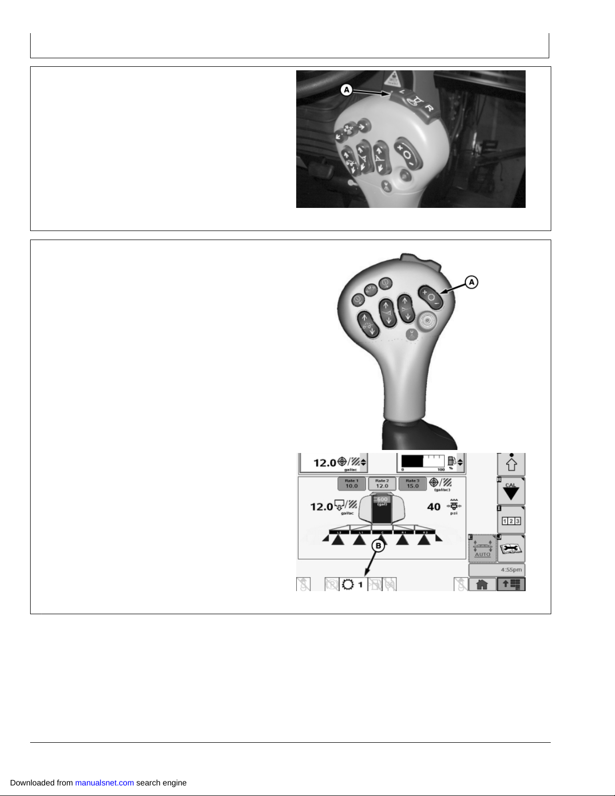
Operators Station
Foam Marker Switch—If Equipped
Foam marker switch (A) on multifunction control handle is
a twofunction switch used to select righthand or lefthand
foam markers. Foam marker system is turned off by
pressing center of switch or both “L” and “R” switches at
same time.
A—Foam Marker Switch
Speed Range Switch
Press top of switch (A) to select higher speed range.
Speed range (B) appears on Sprayer Main Page.
A—Speed Range Switch B—Speed Range
N83091 —UN—04FEB09
OUO6092,0000113 1911MAY091/1
N63293 —UN—15JUL03N82362 —UN—25NOV08
OUO6092,0000115 1924NOV081/1
Downloaded from manualsnet.com search engine
2010
122309
PN=44
Page 45

Operators Station
Spray System Master ON/OFF Switch
Press switch (A) to turn enabled boom sections on and
press again to turn off.
LED in center of switch will illuminate when switch is on.
Sections (B) that are actively spraying once Master
ON/OFF switch is pressed, will appear on display with a
dark background and a lighter letter with a cone showing
below the section.
A—Switch B—Sections
N63294 —UN—15JUL03N82363 —UN—25NOV08
OUO6092,0000114 1924NOV081/1
Downloaded from manualsnet.com search engine
2011
122309
PN=45
Page 46

Operators Station
Boom Raise/Lower Switches
NOTE: The button function shown is the function
assuming boom is fully unfolded. Depressing and
holding boom fold mode switch (D) will change
the function of the boom raise/lower switches to
the function shown in ( ). See Boom fold/unfold
procedures in Boom Section.
Push top of switch (A) to raise the boom center section
and bottom of switch to lower the boom center section.
Push top of switch (B) to raise lefthand boom sections
and bottom of switch to lower lefthand boom sections.
Push top of switch (C) to raise righthand boom sections
and bottom of switch to lower righthand boom sections.
A—Center Boom Raise/Lower
Switch
B—LeftHand Boom
Raise/Lower (Fold/Unfold)
Switch
C—RightHand Boom
Raise/Lower (Fold/Unfold)
Switch
D—Boom Fold Mode Switch
IBS Index Boom Section Buttons
Use IBS Left Button (A) to sequentially shut off individual
boom sections starting at righthand end of boom moving
to the left.
Use IBS Reset Button (B) to restart all shutoff sections
that are enabled.
Use IBS Right Button (C) to sequentially shut off individual
boom sections starting at lefthand end of boom moving
to the right.
N63295 —UN—15JUL03N83819 —UN—31MAR09
OUO6092,0000274 1913OCT091/1
See Operating IBS in Operating The Machine section for
detailed procedures.
A—IBS Left Button
B—IBS Reset Button
Downloaded from manualsnet.com search engine
C—IBS Right Button
2012
N63297 —UN—15JUL03
OUO6092,0000275 1913OCT091/1
122309
PN=46
Page 47

Operators Station
Solution Pump Switch
Push solution pump switch (A) forward to engage pump
for spraying operations. Pull back to disengage.
A—Solution Pump Switch
Agitation Switch
Press agitation switch (A) forward to start agitation. Pull
back to disengage.
Solution pump must first be engaged for agitation to occur.
A—Agitation Switch
N82185 —UN—03NOV08
OUO6092,0000118 1929OCT081/1
Lefthand and Righthand Fence Row
Nozzles Switches—If Equipped
Push left or right fence row nozzle switches (A) forward
to engage left or right side fence row nozzle. Pull back
to disengage.
When the fence row nozzle is turned on, a cone (B) or (C)
will appear at the end of the boom sections on Sprayer
Main Page.
NOTE: Fence row nozzle will not operate if outer section
(L2 or R2) on corresponding side is not enabled.
A—Fence Row Nozzle Switches
B—Cone
C—Cone
N82186 —UN—03NOV08
OUO6092,0000119 1929APR091/1
N82187 —UN—03NOV08N82364 —UN—25NOV08
Downloaded from manualsnet.com search engine
2013
OUO6092,000011A 1924NOV081/1
122309
PN=47
Page 48

Operators Station
Ladder Switch
Ladder will automatically raise when machine moves
forward at speeds greater than 1 mph and will
automatically lower when machine is shut off.
Ladder will lower automatically after leaving seat for 3
seconds.
Ladder may also be raised by pulling switch (A) toward
rear of machine or lowered by pushing switch toward front
of machine.
A—Ladder Switch
Tread Adjust Switches
NOTE: All machines come equipped with side
select (A), front (B), and rear (C) tread adjust
switches, even those equipped with manually
adjusted tread. Switches are inactive when
equipped with manual tread.
A—Side Select Tread Adjust
Switch
B—Front Tread Adjust Switch
C—Rear Tread Adjust Switch
Throttle
Push throttle (A) forward to increase engine speed.
Pull back to decrease.
A—Throttle
N82365 —UN—25NOV08
OUO6092,000011B 1924NOV081/1
N80056 —UN—26FEB08
OUO6092,000011C 1916MAR091/1
Downloaded from manualsnet.com search engine
2014
N82189 —UN—03NOV08
OUO6092,0000276 1913OCT091/1
122309
PN=48
Page 49

Operators Station
Storage Rack
The sprayer may be equipped with a storage rack for a
portable "Field Office". The "Field Office" briefcase can be
secured to the storage rack when the sprayer is in motion.
Press the handle (A) down until it clicks into the rack.
For safety reasons, never drive the sprayer with the
briefcase open. The contents of the briefcase should not
exceed a weight of 10 kg (22 lb).
A—Handle
Load Center
Load Center (A) fuses and relays are located under the
storage rack.
A—Load Center
N82603 —UN—15JAN09
OUO6092,0000277 1913OCT091/1
Diagnostic Outlet
Diagnostic outlet (A) is used by your John Deere dealer
for service and diagnostic purposes only.
A—Diagnostic Outlet
N82200 —UN—10NOV08
OUO6092,0000278 1913OCT091/1
N82201 —UN—10NOV08
OUO6092,0000279 1913OCT091/1
Downloaded from manualsnet.com search engine
2015
122309
PN=49
Page 50

Heater and Air Conditioning Controls
Operators Station
A—Air Conditioning Switch
B—Air Conditioning
Temperature Control
C—Heater Temperature Control
D—Fan Speed Switch
Fan and Air Louvers
The four fan speeds are controlled by switch (A). The
general direction of the airflow can be altered by means
of air louvers (B).
A—Fan Speed Switch
B—Air Louvers
N82190 —UN—03NOV08
OUO6092,000011E 1913JUL091/1
N82191 —UN—03NOV08N82192 —UN—12NOV08
Heater
Heating is infinitely variable by means of the heater
temperature control (A). To increase heating effect, turn
control knob clockwise. Set the fan and louvers to the
desired position.
For best heating results, open the two front air louvers
halfway and position them in a 45° to 55° angle to the
front/down. Close the center and rear air louvers.
A—Heater Temperature Control
Downloaded from manualsnet.com search engine
2016
OUO6092,000011F 1908JUL091/1
N82193 —UN—03NOV08
OUO6092,000027A 1913OCT091/1
122309
PN=50
Page 51

Operators Station
Air Conditioning System
Turn on air conditioning system at switch (A). Regulate
the cooling effect at control (B). The cooling effect is
increased by turning the knob further counterclockwise.
Set the fan and louvers to the desired position.
IMPORTANT: To maintain a consistently high
performance, turn on the air conditioning
system for two or three minutes once every
month, regardless of weather conditions or
season (with engine at low idle). Control (B)
should be set for maximum cooling effect.
At ambient temperatures below 4 °C (39 °F),
the cab should first be heated (using the
heating system) so that the temperature inside
the cab is as high as possible.
N82194 —UN—03NOV08
A—Air Conditioning Switch B—Air Conditioning
Temperature Control
OUO6092,0000121 1915APR091/1
Operating Tips About Your Audio System
Hearing damage from loud noise is almost undetectable
until it is too late. Your hearing can adapt to high volumes
of sound. Sound that seems normal can be loud and
harmful to your hearing. Take precautions by adjusting
the volume control on your receiver to a safe sound level
before your hearing adapts to it.
To help avoid hearing loss:
Adjust the volume control to the lowest setting.
•
Increase the volume slowly until you hear comfortably
•
and clearly.
Understanding Radio Reception
FM STEREO: FM stereo will give you the best sound,
but FM signals will reach only about 1665 km (1040
miles). Tall buildings or hills can interfere with FM signals,
causing the sound to come and go.
AM: The range for most AM stations is greater than for FM,
especially at night. The longer range, however, can cause
stations to interfere with each other. AM can pick up noise
from things like storms and power lines. Try reducing the
treble to reduce this noise if you experience it.
IMPORTANT: Before you add any sound equipment to
your machine like a CB radio, mobile telephone
or twoway radio, be sure you can add what
you want. If you can, it’s very important to do it
properly. Added sound equipment may interfere
with the operation of your vehicle’s engine,
sprayer control unit, radio or other systems,
and even damage them. See your John Deere
dealer for proper installation instructions.
Your vehicle’s systems may interfere with
the operation of sound equipment that has
been added improperly. Before adding sound
equipment, check with your dealer and be
sure to check Federal Regulations covering
mobile radio and telephone units.
OUO6092,0000728 1918OCT041/1
Downloaded from manualsnet.com search engine
2017
122309
PN=51
Page 52

Operators Station
AUX
INPUT
DSPL/
SETUP
TUNE/
SEEK
AUX
BAND
TIME
ALARM
CLOCK
RDM RPT REVFF
1 2 3 4 5 6
PUSH
SCAN/
PSCAN
AUTO
STORE
M
A
B
C D
H
E
F
G
I
J
L
K
DeereDelco AM/FM Stereo Radio, CD Player, and Weatherband
H91085 —UN—08APR08
A—Power Button
B—AUDIO Dial
C—Auxiliary (AUX) Button
D—Display/Time (DSPL/TIME)
Button
E—TUNE/SEEK (Forward) Button
F— TUNE/SEEK (Reverse) Button
G—BAND Button
H—Alarm Clock Button
Turning ON Power
With key switch ON, the receiver turns ON or OFF by
pressing power button (A). Pressing AUDIO dial also
activates receiver.
Adjusting Receiver Settings (AUDIO Dial (B))
To adjust the following, press and release AUDIO dial
repeatedly until desired feature appears on display.
Volume Volume is the default function. Rotate dial
•
clockwise to increase volume and counterclockwise to
decrease it. Display shows "VOL" and volume level.
After five seconds, display will revert to the default
display.
Bass Press dial until "BASS" and present level appear
•
on display. Rotate dial clockwise to increase bass
sound and counterclockwise to decrease it. After five
seconds, display will revert to the default display.
Treble Press dial until "TREB" and present level
•
appear. Rotate dial clockwise to increase treble sound
and counterclockwise to decrease it. After five seconds,
display will revert to the default display.
Balance Press dial until "BAL" and present level
•
appear. Rotate dial clockwise to move sound to right
speakers and counterclockwise to move sound to left
speakers. After five seconds, display will revert to the
default display.
Fade Press dial until "FADE" and present level appear
•
on display. Rotate dial clockwise to move sound to front
speakers and counterclockwise to move sound to rear
speakers. After five seconds, display will revert to the
default display.
Seek Sensitivity – Press dial until “SEEK” and
•
sensitivity levels appear on display. Rotate dial
clockwise to increase sensitivity or counterclockwise
to decrease sensitivity. Increasing helps find more
Downloaded from manualsnet.com search engine
I— Preset Buttons (1—6)
J— Auxiliary (AUX) Input
K—Auto Store Button
L— SCAN/PSCAN Button
stations, including weaker ones. Decreasing causes
fewer stations, but stronger stations.
Dimming Press dial until ”DIM” and brightness level
•
appear on display. Rotate dial clockwise to increase
brightness or counterclockwise to decrease brightness.
After five seconds, display will revert to the default
display.
Speakers – Press dial until “SPEAKER4” or
•
“SPEAKER2” appear on display. Rotate dial clockwise
to toggle between two speakers or four speakers.
Auxiliary (CD/AUX) Button (C)
Enables radio to play an external audio source like an
MP3 player that is connected to auxiliary audio input jack.
To use an external device:
1. Plug device into auxiliary input jack.
2. Press CD/AUX button until “AUX IN” appears.
When external device is connected and turned ON, you
will be able to listen to it. If CD/AUX button is pressed and
no device is connected, radio displays “NO AUX”.
To mute auxiliary mode, press preset 1 button. Press
preset 1 button again to resume listening to external
device.
When external audio source is enabled, display shows
“EX AUDIO”. Pressing CD/AUX button toggles between
radio, CD, or external audio device. After five seconds,
display will revert to the default display.
To turn OFF auxiliary mode:
1. Press CD/AUX button or BAND button until radio
changes to mode desired.
2. Unplug external device from auxiliary input jack.
Continued on next page OUO1078,0000231 1903MAR091/3
2018
M—Eject Button
122309
PN=52
Page 53

Operators Station
Display (DSPL/TIME) Button (D)
Radio Function: Pressing DSPL/TIME button when
receiver is ON toggles between frequency and current
time.
CD Player Function: Pressing DSPL/TIME button when
receiver is ON toggles between track number/elapsed
time and current time.
Setting Time Format and Clock
Radio can be set to a 12/24 Hour Time Format. Entering
time set mode changes time format.
Time Format
1. Turn key switch ON.
2. Press and hold DSPL/TIME button until hour and
minute digits flash and a beep is heard.
3. Press preset 5 button to toggle between 12/24 Hour
mode.
4. After five seconds, display will revert to the default
display.
Setting Clock
1. Turn key switch ON.
2. Press and hold DSPL/TIME button until hour and
minute digits flash and a beep is heard.
3. Press DSPL/TIME button again until hour digit flashes.
4. Rotate AUDIO dial to change hour digit. Rotate
clockwise to increase or counterclockwise to decrease.
5. Press DSPL/TIME button again until minute digit
flashes.
6. Rotate AUDIO dial to change minute digit. Rotate
clockwise to increase or counterclockwise to decrease.
7. After five seconds, display will revert to the default
display.
TUNE/SEEK Button (E and F)
Radio Function: Press and hold both forward arrow and
BAND (G) buttons simultaneously for two seconds to
switch between “TUNE” or “SEEK”.
Manual TUNE
1. Press and hold forward arrow and BAND button until
“TUNE” appears on display.
2. To increase radio frequency, press forward arrow to
go to next higher station.
3. To decrease radio frequency, press reverse arrow to
go to next lower station.
SEEK: Press forward or reverse arrow for more than a half
a second turns SEEK mode ON and “SEEK” appears on
display. Seek mode ends when a tunable station is found.
NOTE: If SEEK does not find a tunable station after
searching the band twice, SEEK ends and “NOT
FOUND” appears on display. After five seconds,
default display appears and radio continues to
play station it was previously playing.
To cancel SEEK, press forward or reverse arrow again.
CD Player Function: Press forward arrow to forward to
next rack. Track number and elapsed time appear.
Press reverse arrow to go to beginning of track being
played. Press button within the first eight seconds of track
to go to beginning of previous track. Track number and
elapsed time appear.
Band Button (G)
Band button toggles through FM1, FM2, FM3, AM, and
(Weather) WX. After five seconds, display will revert to the
default display.
Alarm Clock Button (H)
Setting Alarm
1. Turn radio ON.
2. Press ALARM button until “ALARM” icon and “SET”
appear.
3. Hour digit flashes. Rotate AUDIO dial clockwise to
increase or counterclockwise to decrease.
4. Press ALARM button.
5. Minute digit flashes. Rotate AUDIO dial clockwise to
increase or counterclockwise to decrease.
6. Press ALARM button until “SET TONE” appears.
7. Press ALARM button again until “VOL” appears.
8. Press ALARM button again and an alarm tone is
heard.
9. Rotate AUDIO dial clockwise to increase or
counterclockwise to decrease.
10. Press ALARM button again to return to normal
operation.
NOTE: Alarm clock icon is now enabled. Press alarm
clock button again to disable.
Turn Alarm OFF
Press ALARM button until a beep is heard and alarm
clock icon disappears.
Activate Snooze Alarm
Press any button when alarm sounds to activate snooze.
Alarm sound again in nine minutes.
OneHour Timer
With key switch OFF, press PWR (Power) button or
AUDIO dial to activate onehour timer.
Receiver will turn OFF after one hour.
Preset Buttons (1—6) (I)
Preset buttons allow you to preset six favorite stations per
band and easily return to them with a touch of a button.
18—FM channels, 6AM channels, 6WX (weather
band) channels can be stored for immediate recall using
preset buttons 1—6 (six memories for each band FM1,
FM2, FM3, AM, and WX).
Radio Function: (Setting Favorite Stations)
1. Turn receiver ON.
2. Select desired band (FM1, FM2, FM3, AM).
Continued on next page OUO1078,0000231 1903MAR092/3
Downloaded from manualsnet.com search engine
2019
122309
PN=53
Page 54

Operators Station
3. Tune to desired listening station.
4. Push desired preset button (1—6) and hold for more
than two seconds to store selected station.
NOTE: When station has been set to preset number,
a beep and preset number is visible.
Press preset button later tunes radio station to that was
previously selected station.
CD Player Function:
Preset 1/PAUSE Button – Pauses current CD. “PAU”
•
displays and audio is muted. Press button again to
resume play of CD.
Preset 2/RDM Button – Activates random track
•
selection. “RDM” icon displays and tracks on loaded
disc play in random order. Press button again to turn
OFF random play.
Preset 3/RPT Button – Repeats current track. “RPT”
•
displays and track currently playing repeats. Press
button again to turn OFF repeat.
Preset 5/FF Button – fastforwards through current
•
track. Upon release, CD plays at normal speed. Display
shows track number and elapsed time.
Preset 6/REV Button – Reverses through current
•
track. Up release, CD plays at normal speed. Display
shows track number and elapsed time.
Auxiliary Audio Input (J)
Enables radio to play an external audio source like an
MP3 player that is connected to auxiliary audio input jack.
When auxiliary (AUX) button is enabled, display shows
“EX AUDIO”.
FM3). When a preset frequency of sufficient strength is
found, radio plays for five seconds and then continues
scanning. Display shows “PSCAN”, frequency, preset
number, and current band. Preset scan continues until
SCAN/PSCAN button is pressed again.
CD Player Function:
Press SCAN/PSCAN button to scan all tracks on CD.
Player immediately advances to next track. After playing
ten seconds of current track, player automatically goes to
next track. To end track scan, press SCAN/PSCAN again.
EJECT Button (M)
Pressing EJECT button ejects disc.
Playing a Compact Disc
1. Turn key switch ON.
2. Insert disc part way into slot (label side up). Player
automatically pulls disc in once it has been partially
inserted. “CD” icon and “LOADING” appears on
display followed by track number and elapsed time
and disc begins to play.
3. If listening to AM/FM/WX radio, press CD/AUX button
to play a CD that was already loaded into player. If no
CD is loaded, display shows “NO CD” for five seconds
and return to default display. If a CD was previously
loaded, track number and elapsed time appear on
display.
NOTE: If a CD is ejected and not removed within
16 seconds, CD reloads but does not start
playing until CD/AUX button is pressed.
AUTO STORE Button (K)
Pressing AUTO STORE button automatically stores six
strongest stations on preset buttons (1—6).
Press and hold AUTO STORE button until “AUTO” and
“AS” icon appear. AUTO STORE affects current band
(example: if AUTO STORE button is pressed while
listening to FM1, preset for AM, FM2, FM3, and WX are
not changed). Press and hold AUTO STORE button for
more than two seconds cancels AUTO STORE, and
original presets are stored.
SCAN/PSCN Buttons (L)
Radio Function:
SCAN: Press SCAN/PSCAN button to scan all stations
on band selected. When a frequency of sufficient strength
is found, radio plays for five seconds and continues
scanning until SCAN/PSCAN button is pressed again.
Display shows “SCAN” and frequency being scanned.
PSCAN: Press SCAN/PSCN button to scan presets on
band to which you are currently using (FM1, FM2, and
Troubleshooting CD Player
The following error messages may appear while playing
a compact disc:
NO CD: No CD has been loaded into player.
FOCUS: Lens could not focus on disc. Possible reasons
included:
Disc is inserted upside down – Eject disc and reinsert
•
disc.
Disc is dirty, scratched, or wet – Try cleaning disc.
•
Lens is dirty – Clean disc lens with a lens cleaner.
•
It is very humid – Wait an hour and try again.
•
TRACKING: Loss of tracking control. Possible reasons
include:
Disc is dirty or scratched – Try cleaning disc.
•
Lens is dirty – Clean disc lens with a lens cleaner.
•
Disc is stuck and could not spin – Contact dealer.
•
LOAD: Load/unload motor problem – Contact dealer.
OUO1078,0000231 1903MAR093/3
Downloaded from manualsnet.com search engine
2020
122309
PN=54
Page 55

Operators Station
Program Radio for Local Area Frequency
To verify that the radio is set for North American
frequencies:
1. Turn key switch ON.
2. Turn radio OFF (digital display shows current time).
3. Press and hold the DSPL/TM SET button until hour
digits start to flash.
NOTE: When radio displays “USA”, do not press
any buttons until the radio display returns
to the current time.
4. Immediately press BAND button once.
Radio can be programmed for use in the U.S.A. (North
America), China, Europe, Argentina or Japan. For use in
Australia, set radio to “EUROPE” setting.
To program radio:
1. Turn key switch ON.
Weatherband
All of the John Deere radios are equipped with
Weatherband channel.
NOAAWeather Radio is a service of the “Voice of
the National Weather Service.” It provides continuous
broadcasts of the latest weather information directly from
the National Weather Service offices. Taped weather
messages are repeated every four to six minutes and
are routinely revised every one to three hours or more
frequently if needed. Most of the stations operate 24
hours daily.
The weather for the area you are in may be found on one
of seven stations. When in the Weatherband mode the
2. Turn radio OFF (digital display shows current time).
3. Press and hold DSPL/TM SET button until hour digits
start flashing.
4. Immediately press BAND button to view current setting
on digital display.
Repeatedly press BAND button to scroll through
available area settings:
U.S.A.
•
EUROPE (Use for Australia)
•
JAPAN
•
ARGENTINA
•
CHINA
•
Stop pressing BAND button when desired area appears.
Do not press any buttons for a few seconds; new area
frequency setting is in use when display returns to show
current time.
OUO6092,00000BB 1908JUL091/1
display will show the “WX” icon and “CHAN #” to indicate
the channel. The channel may be adjusted through the
TUNE or SEEK buttons. The channels may be set on the
presets just like you are setting the radio.
The frequency associated with each channel is as follows:
1 162.550 MHz
•
2 162.400 MHz
•
3 162.475 MHz
•
4 162.425 MHz
•
5 162.450 MHz
•
6 162.500 MHz
•
7 162.525 MHz
•
OUO6092,0000729 1918OCT041/1
Downloaded from manualsnet.com search engine
2021
122309
PN=55
Page 56

Operators Station
Dome Light and Console Light
The dome light is controlled using a three position switch
(A).
OFF position
•
ON position—Interior convenience light will illuminate
•
when the cab door is opened and will go out when the
door is closed.
ON position—Interior convenience light will illuminate
•
until the switch is returned to either of the other two
positions.
The console light (B) illuminates the area of
CommandARM™ when the parking lights or headlights
are switched on.
A—Dome Light Switch B—Console Light
CommandARM is a trademark of Deere & Company
Switches at BPost
A—Secondary Brake Switch
B—Traction Control Switch (If
Equipped)
C—Beacon Light Switch (If
Equipped)
N82345 —UN—13NOV08
Dome Light
N82346 —UN—13NOV08
Console Light
OUO6092,000012D 1908JUL091/1
Downloaded from manualsnet.com search engine
2022
N82197 —UN—18DEC09
OUO6092,0000127 1910JUL091/1
122309
PN=56
Page 57

Operators Station
Using Secondary Brake
In the event that primary (hydro) and service (brake pedal)
systems are not operating correctly, press the secondary
brake switch (A).
IMPORTANT: The secondary brake engages the
park brake system. Engaging secondary
brake system while machine is moving causes
significant wear to the park brake components.
Park brakes will need to be tested to verify
proper operation after using the secondary
brake. (See Verify Proper Operation Of Park
Brakes in Operating The Machine section.)
N82198 —UN—18DEC09
NOTE: Secondary brake switch does not need to be
engaged when parking machine. Park brakes
are automatically applied when multifunction
control handle is placed in the “PARK” position
and the SprayStar system reads “0” mph for 0.5
seconds or the engine is shut “OFF”.
Traction Control (Optional)
Traction control system is designed to provide additional
tractive effort when needed. Use switch to engage
and disengage system. See Operate Traction Control
(Optional) in Operating The Machine section of this
manual for operating details.
A—Traction Control Switch
A—Secondary Brake Switch
OUO6092,0000128 1910JUL091/1
N82199 —UN—18DEC09
OUO6092,0000129 1906NOV081/1
Downloaded from manualsnet.com search engine
2023
122309
PN=57
Page 58

Operators Station
Operate Beacon Light (If Equipped)
The rotary beacon light (A) (not authorized in all countries)
should be used when driving extremely slowly and when
vehicle width is excessive. Use switch (B) to turn light
on and off.
A—Beacon Light
B—Switch
Operator’s Seat
IMPORTANT: Park vehicle and shut off engine
before doing seat adjustments.
N84590 —UN—04MAY09N84589 —UN—18DEC09
OUO6092,0000209 1906JUL091/1
The operator’s seat has an air suspension system for
added operator comfort. The seat has a selfcontained
electric compressor to adjust the seat suspension to
match the operator’s height and weight. Seat adjustments
are as follows:
Attenuator lockout handle (A) locks out or releases the
forward or rearward movement. Pull up on the handle to
lock; push down on the handle to release.
The forward/rearward adjustment handle (B) allows the
seat to slide forward or rearward for best working position.
Pull up on handle (C) to adjust seat back angle. Release
handle when seat back is in desired position.
Height adjustment is made with handle (D). To raise the
seat, pull up on the handle. To lower the seat, push down
on the handle.
A—Forward/Rearward
Attenuator LockOut
Handle
B—Forward/Rearward
Adjustment Handle
N82195 —UN—03NOV08
C—Seat Back Angle
Adjustment Handle
D—Height Adjustment Handle
OUO6092,0000122 1926MAR091/1
Downloaded from manualsnet.com search engine
2024
122309
PN=58
Page 59

Operators Station
Seat Belts
Seat belts are standard equipment on the operator seat
and should be used every time machine is operated. The
lap type seat belts have push button quick release and
automatic belt retraction to allow unrestricted exiting and
entering of the seats.
CAUTION: Inspect the seat belt and mounting
hardware on your machine at least once a year.
If the seat belt system, including the mounting
hardware, buckle, belt or retractor, shows any
sign of damage such as cuts, fraying, extreme
or unusual wear, discoloration or abrasion,
the entire seat belt system should be replaced
immediately. For your safety, replace the belt
system only with replacement parts approved for
your machine. (See your John Deere dealer.)
Instructional Seat—If Equipped
CAUTION: This instructional seat has been
provided only for training operators or
diagnosing machine problems. Keep all other
riders off of the machine. Always wear seat belt.
H67084 —UN—02APR01
OUO6092,0000123 1902JUL091/1
Unlatch lock lever (A) to fold seat up or down.
A—Lever
Adjust Rearview Mirrors
Adjust righthand (A) and lefthand (B) mirrors for desired
rear visibility by pivoting mirror heads.
A—Righthand Mirror
B—LeftHand Mirror
N83820 —UN—31MAR09
OUO6092,0000124 1908JUL091/1
N84591 —UN—19MAY09
OUO6092,000012C 1911MAY091/1
Downloaded from manualsnet.com search engine
2025
122309
PN=59
Page 60

BreakIn Checks—First 100 Hours
Breakin Period
Engine is ready for normal operation.
Tighten lug nuts after first hour of use and daily during
the first week of operation.
Check for leaks.
Operate engine at heavy loads without sustained
maximum load.
Avoid idling the engine longer than 5 minutes.
Closely observe coolant temperature during operation.
Check air intake system hoses and clamps.
Daily or Every 10 Hours
IMPORTANT: John Deere BreakIn™ or John Deere
BreakIn Plus oil must be added if oil level is
below the ADD mark on dipstick. DO NOT fill
above the crosshatch pattern or the FULL mark.
Check engine oil level frequently.
•
Check coolant level frequently.
•
Check hydraulic oil level
•
Drain water and sediment from water separator.
•
Inspect tires for damage and correct inflation.
•
Check air springs for proper inflation.
•
BreakIn is a trademark of Deere & Company
At 50 Hours
Change planetary hub oil
•
Visually inspect suspension rod bushings
•
At 100 HOURS
IMPORTANT: Refill with John Deere Breakin Oil for
an additional 100 hours, if sprayer was used
under light load conditions during first 100
hours, to allow engine to breakin properly. (See
Fuels, Lubricants and Coolant Section.)
Change engine oil and filter.
•
Visually inspect suspension rod bushings
•
Check suspension rod hardware torque. (See Check
•
Suspension Rod Hardware—After First 100 Hours in
Lubrication and Maintenance section.)
Check tread adjust shim gap. (See Check Shim Gap on
•
Axle Tread Adjust—After First 100 hours in Lubrication
and Maintenance section.)
Inspect machine for loose hardware.
•
NOTE: Reset service hours to zero after service.
(See Resetting Service Interval Counter
in SprayStar section.)
OUO6092,00002CC 1902DEC091/1
Downloaded from manualsnet.com search engine
251
122309
PN=60
Page 61

Prestarting Checks
Check Engine Oil Level—Daily
Remove dipstick (A) and check oil level with sprayer on
level ground. Oil level should be between the “ADD” and
the top of the crosshatch area on dipstick. If needed,
add oil recommended in Diesel Engine Oil in the Fuels,
Lubricants, And Coolants section.
Do not operate engine with oil level below the “ADD” mark
on dipstick.
A—Dipstick
Drain Water and Sediment from Fuel Filter
and Water Separator—Daily
IMPORTANT: When draining water from fuel filters,
the drain valve must be unthreaded completely
and the valve must drop down approximately 12
mm (0.5 in.) to properly drain water from filter.
Drain water and contaminates from water separator bowl
by opening the drain valve (A) on the primary (B) and
secondary (C) filters.
N82366 —UN—27MAY09
OUO6092,00000BF 1904DEC081/1
A—Drain Valve
B—Primary Filter
C—Secondary Filter
Check Coolant Level—Daily
1. Raise hood.
2. Check coolant level at expansion tank, before starting
sprayer. Level should be slightly above “MIN” mark (B)
and below “MAX” mark (A) when engine is cold.
3. If coolant level is low;
a. Check for any signs of leakage. Repair if necessary.
b. Tighten all hose clamps.
c. Remove tank cap (C) and add coolant, as specified
in Fuel, Lubricants and Coolant section.
d. Lower hood.
A—Maximum Level
B—Minimum Level
N82367 —UN—27MAY09
OUO6092,00000C0 1909JUL091/1
N82443 —UN—11DEC08
LeftHand Side
C—Cap
OUO6092,00000C1 1907JUL091/1
Downloaded from manualsnet.com search engine
301
122309
PN=61
Page 62

Prestarting Checks
Check Hydrostatic and Hydraulic Oil Level—Daily
NOTE: Place booms in boom rests and retract
all hydraulic cylinders including tread adjust
cylinders when checking oil level.
Hydraulic system capacity is approximately 151 L (40 gal)
and reservoir capacity is 60.6 L (16 gal).
Hydraulic oil level showing should be onehalf to
threequarters full in sight gauge (A). Add oil through
opening at filler cap (B) if necessary. (See Fuels,
Lubricants and Coolant section of machines Operators
Manual for hydraulic oil specifications.)
A—Sight Gauge B—Filler Cap
N82444 —UN—11DEC08N83822 —UN—31MAR09
Fill Fuel Tank
CAUTION: Shut off engine before filling fuel tank.
NOTE: Fuel tank capacity is 269 L (71 gal).
Remove fuel tank cap (A). Fill tank with proper grade of
diesel fuel. (See Lubrication And Maintenance section for
diesel fuel specifications.)
A—Fuel Tank Cap
OUO6092,00000BD 1911MAY091/1
N82445 —UN—11DEC08
OUO6092,00000BE 1909JUL091/1
Downloaded from manualsnet.com search engine
302
122309
PN=62
Page 63

Prestarting Checks
Check Tires For Damage And Correct
Inflation Pressure—Daily
4630 Tires
Tires/Air Pressure kPa bar psi
320/80R42 320 3.2 46
380/80R38 240 2.4 35
420/85R34 180 1.8 29
Explosive separation of a tire and rim parts can cause
serious injury or death.
Do not attempt to mount a tire unless you have the proper
equipment and experience to perform the job.
Always maintain the correct tire pressure. Do not inflate
the tires above the recommended pressure. Never weld
or heat a wheel and tire assembly. The heat can cause
an increase in air pressure resulting in a tire explosion.
Welding can structurally weaken or deform the wheel.
When inflating tires, use a clipon chuck and extension
hose long enough to allow you to stand to one side and
NOT in front of or over the tire assembly. Use a safety
cage if available.
Check wheels for low pressure, cuts, bubbles, damaged
rims or missing lug bolts and nuts.
TS211 —UN—23AUG88
Check Air Springs—Daily (Machines
not Equipped with Auto Air Spring
Leveling System)
CAUTION: Air spring can explode if over inflated
causing serious injury or death to you or others.
When adjusting suspension assemblies, do not
exceed 689 kPa (6.89 bar) (100 psi). Keep hands
and body away from suspension linkage.
NOTE: Machines should be parked on level ground with
booms in folded position when checking air springs.
It is normal for air springs to lose air after a few
days of use, especially in rough terrain.
Inspect air spring assemblies (A) for proper air bag
inflation daily.
Inflate air springs to the following specifications.
OUO6092,00000C2 1915APR091/1
N82612 —UN—26JAN09
Left Rear Air Spring Assembly Shown
A—Distance Between Air
Spring Mounting Plates
Air Spring Settings
Air Spring Dimension Solution Tank Empty Solution Tank Full
Front Setting 175 mm (7 in.) 165 mm (6.5 in.)
Rear Setting 240 mm (9.5 in.) 185 mm (7.25 in.)
OUO6092,0000238 1930JUL091/1
Downloaded from manualsnet.com search engine
303
122309
PN=63
Page 64

Prestarting Checks
Lubricate Suspension Assemblies—Daily
Lubricate front suspension assemblies with John Deere
SD Polyurea Grease. Use three pumps of grease at each
fitting (A).
IMPORTANT: Use of other greases in the suspension
system is not recommended. Use of other
greases can result in premature wear of
the suspension components.
A—Grease Fitting
N82613 —UN—26JAN09
Right Front Assembly (Narrow Body Shown)
304
N82614 —UN—26JAN09
Narrow Body Left Front Assembly (Narrow Body Shown)
OUO6092,00000C4 1924APR091/1
122309
PN=64
Downloaded from manualsnet.com search engine
Page 65

Prestarting Checks
Drain Moisture from On Board Air
Tank—Daily
CAUTION: Unloader valve and tank exhaust
at high pressure. Protective eyewear
should be worn when servicing or relieving
pressure through petcock.
When foaming, the compressor will go over relief
approximately every 30 seconds. When idle, it
will go over relief every few seconds.
Open petcock (A) and drain moisture from on board air
tank daily.
A—Petcock
TS266 —UN—23AUG88N82451 —UN—11DEC08
OUO6092,00000C5 1905DEC081/1
Downloaded from manualsnet.com search engine
305
122309
PN=65
Page 66

Operating The Machine
Machine Informational Decals
Secondary Braking Decal
IMPORTANT: The secondary brake engages the
park brake system. Engaging secondary
brake system while machine is moving causes
significant wear to the park brake components.
Park brakes will need to be tested to verify
proper operation after using the secondary
brake. (See Verify Proper Operation Of Park
Brakes in Operating The Machine section.)
NOTE: Secondary brake switch does not need to be
engaged when parking machine. Park brakes
are automatically applied when multifunction
control handle is placed in the "PARK" position
and the SprayStar system reads "0" mph for 0.5
seconds or the engine is shut "OFF".
Start the Engine
CAUTION: Prevent asphyxiation. Engine
exhaust fumes can cause sickness or
death to you or others.
N85454 —UN—21JUL09
A—Secondary Braking Switch
OUO6092,00002EF 1923DEC091/1
If you must operate engine in a building, be
positive there is adequate ventilation. Use an
exhaust pipe extension to remove the exhaust
fumes or open doors and windows to bring
enough outside air into the area.
Avoid the possibility of personnel injury or death:
Be sure everyone is clear of the machine.
•
Start engine only from the operator seat.
•
Do not start engine by shorting across
•
starter terminals. Machine may start in gear
if normal circuitry is bypassed.
Engine starting with the handle out of the
•
“Park” position indicates a malfunction of
the starting circuit. Repairs should be made
immediately by your John Deere Dealer.
TS220 —UN—23AUG88TS177 —UN—11JAN89
Continued on next page OUO6092,00000CF 1908JUL091/3
Downloaded from manualsnet.com search engine
351
122309
PN=66
Page 67

Operating The Machine
NOTE: Controls and switches must be in the position
described, before starting the engine.
1. Turn off switches, including radio and dome light.
2. Place multifunction control handle (A) in “Park”.
NOTE: If temperature below 5° C (40° F), refer to Cold
Weather Starting in this section.
3. Turn ignition key to “Run” position. Stop, Preheating,
and Caution Indicator lights (B) will come on when key
is in “Run” position and engine is not running.
4. Put throttle in slow idle position (approximately 1/3 of
full throttle).
N82185 —UN—03NOV08N82615 —UN—26JAN09
A—Multifunction Control
Handle
B—Indicator Lights
IMPORTANT: Do not operate starter more than 30
seconds at a time or starter may be damaged. If
engine does not start, wait at least 2 minutes
before trying again. If engine does not start in
four attempts, refer to Troubleshooting section.
To assure adequate lubrication after engine
starts, idle engine at approximately 1000 rpm
with no load for 1 to 2 minutes. Extend this period
when operating at temperatures below freezing.
When starting the machine during cold
temperatures see Cold Weather Starting
in this section.
OUO6092,00000CF 1908JUL092/3
N84161 —UN—08APR09
5. Turn ignition key to Start position to engage starter.
Release key when engine starts. If key is released
before engine starts, wait until starter and engine stop
turning before trying again.
6. When the engine has started the indicator lights will
go off when ignition key is released.
7. View the engine coolant temperature on Sprayer Main
Page if that feature has been selected on one of the
dropdown menus available on that page.
Downloaded from manualsnet.com search engine
A—Drop Down Menu
IMPORTANT: Protect turbocharger during startup by
not accelerating above 1000 rpm until normal
engine idle speed is established (900 rpm).
NOTE: Should engine stall while operating under load,
restart it immediately to prevent overheating.
OUO6092,00000CF 1908JUL093/3
352
122309
PN=67
Page 68

Operating The Machine
Cold Weather Starting
IMPORTANT: Do not use ether or starting fluids to
start engine with a cold weather starting device.
Ether is highly flammable and could ignite on
engines with a cold weather starting device.
Machine is equipped with an intake air preheating system.
An electric heating element warms the intake air.
1. Turn off switches, including radio and dome light.
2. Place multifunction control handle in “Park”.
3. Put throttle in slow idle position (approximately 1/3 of
full throttle).
4. Turn key (B) to “Run” position. The intake air
preheating system will be activated, as necessary,
according to fuel temperature. The preheating
indicator light will illumnate from 0 to 30 seconds.
IMPORTANT: Avoid starter damage. Do not operate
starter more than 30 seconds at a time.
If engine does not start, wait at least two
minutes before trying again.
Warm The Engine
Do not place engine under full load until it is properly
warmed. View the engine coolant temperature (A) on
Sprayer Main Page if that feature has been selected on
one of the dropdown menus available on that page.
IMPORTANT: To provide proper lubrication after
engine starts, operate engine at approximately
900 rpm, with no load for 1 to 2 minutes. At
temperatures below freezing point, this period
must be extended to 2 to 4 minutes.
At temperatures below freezing, as engine and
hydraulic fluid are warming, turn steering wheel
back and forth to circulate warm hydraulic
fluid until front wheels can be turned freely
from locktolock positions.
N82616 —UN—26JAN09
A—Preheating Indicator
5. When preheating indicator light goes out, turn key
switch to “Start” position to engage starter. Release
key when engine starts.
6. Idle engine at 900 rpm until it warms to operating
temperature.
OUO6092,00000D0 1908APR091/1
N84188 —UN—14APR09
A—Coolant Temperature
Downloaded from manualsnet.com search engine
353
OUO6092,00001CF 1908JUL091/1
122309
PN=68
Page 69

Operating The Machine
Idle the Engine
Allowing the engine to idle uses fuel inefficiently and can
cause a buildup of carbon in the engine.
If machine must be left with the engine running for more
than 3 or 4 minutes, minimum engine speed should be
1000 rpm.
View the engine rpm’s (A) on Sprayer Main Page if that
feature has been selected on one of the dropdown menus
available on that page. Push forward on throttle lever (B)
until desired RPM is displayed.
A—Engine Speed
B—Throttle Lever
N84189 —UN—14APR09N82617 —UN—26JAN09
Operate the Engine
Restarting Stalled Engine:
Restart stalled engine IMMEDIATELY to prevent excessive
heat buildup and possible turbocharger damage.
Stopping the Engine:
Operate Warning Lights
CAUTION: When transporting the machine on
a road or highway at night or during the day,
use lights and devices for adequate warning
to operators of other vehicles. Check local
governmental regulations. Various safety
devices are available from your John Deere
dealer. Keep safety items in good condition.
Replace missing or damaged items.
A—Lights
B—Slow Moving Vehicle
Emblem
C—Reflector Tape
D—Reflectors
OUO6092,00000D2 1908JUL091/1
Stop sprayer and pull throttle back to slow idle position
•
Put multifunction control handle in “Park” position
•
Turn ignition key to “Off” position and remove key.
•
CAUTION: Remove ignition switch key to
help prevent accidents.
OUO6092,00000D1 1920AUG081/1
AG,OUO1011,756 1908JUL091/1
N36564 —UN—10FEB89
Downloaded from manualsnet.com search engine
354
122309
PN=69
Page 70

Operating The Machine
Driving the Machine
1. Ladder will automatically retract when machine moves.
2. Push throttle (A) forward to achieve maximum engine
speed.
A—Throttle
IMPORTANT: Machine damage can occur if speed
range switch is moved from a higher speed
range to a lower speed range causing the engine
to exceed 3000 RPM’s. Speed range can be
changed when machine is moving or stopped.
Drive train damage can occur if multifunction
control handle is advanced more than halfway
when wheels are spinning (loss of traction).
N82189 —UN—03NOV08
OUO6092,0000152 1908JUL091/2
NOTE: When machine is started or has been shut down
and restarted, first speed range is automatically
selected by the Chassis Control Unit (CCU).
3. Push down and release bottom of speed range switch
(A) as many times as needed to place machine in first
speed range.
NOTE: Speed range selected (C) is displayed on
bottom line of Sprayer Main Page.
4. Push multifunction control handle (B) slowly forward to
start forward motion. Continue pushing lever forward
to increase ground speed. Change speed range
switch to higher speed range when engine reaches
maximum RPM.
IMPORTANT: While under a load, engine and
drivetrain overheating can occur if engine
drops below 2000 RPM’s for an extended
period. Pull back slightly on multifunction
control handle to reduce engine load. Maintain
at least 2200 RPM at all times.
5. To reverse direction of travel, move multifunction
control handle to neutral and press brake pedal as
needed to bring machine to a complete stop, then
move handle to the right and rear to back up machine.
A—Speed Range Switch
B—Multifunction Control
Handle
C—Speed Range
6. Always shift to first speed range to achieve maximum
tractive effort in reverse.
OUO6092,0000152 1908JUL092/2
N82618 —UN—12MAY09N84190 —UN—14APR09
Downloaded from manualsnet.com search engine
355
122309
PN=70
Page 71

Operating The Machine
Backup Alarm
If multifunction control handle is moved rearward while
engine is running, backup alarm (A) sends an acoustical
signal to warn others around the machine that the operator
is backing up.
A—Backup Alarm
Before Operating in the Field
N82619 —UN—15APR09
OUO6092,0000153 1906JUL091/1
NOTE: Verify machine is properly prepared for
field operation. Check the following items
before operating:
All maintenance has been performed.
•
Correct nozzle tips are installed and set for desired
•
spray pattern and row spacing. (See Wet System
section for proper nozzle tip and row spacing selection.)
Wheel tread width is adjusted for row spacing. (See
•
Set Tread Width Narrow Machine, Set Tread Width
Wide Machine—Without Hydraulic Tread Adjust Option,
and Setting Tread Width—With Hydraulic Tread Adjust
Option in the Chassis section.)
SprayStar display has been correctly programmed
•
with the following: (See SprayStar System section to
program information properly.)
Application Rates
Tank Volume
Minimum Spray Pressure
Spray Off Pressure
Operate in the Field
1. Unfold boom and press raise/lower switch (A) to
position boom at desired operating height.
2. Setup SprayStar control unit for your particular
application. (See SprayStar System section for proper
setup procedure.)
Number of Boom Sections
Nozzle Spacing
Spray Width
Check Flowmeter Calibration Number
Calibrate Pressure Sensor
Calibrate Wheel Speed Sensor
Calibrate Radar Sensor (if equipped)
Solution tank is filled, solution valves are correctly
•
positioned and agitation valve (if necessary) is open.
(See Wet System section.)
Perform a Nozzle Flow Check test. (See Nozzle Flow
•
Check test in SprayStar section.
Perform the Boom Air Bleed Process in
•
Recommendations For Eliminating Air from
Solution System in the Wet system section.
Operator is familiar with all machine controls, their
•
functions, and safe operations. (See Operators Station
and Safety sections.)
Clean water tank is filled with clean water. (See Clean
•
Water Tank in the Wet System section.)
OUO6092,00000D3 1905JUN091/1
A—Raise/Lower Switch
Downloaded from manualsnet.com search engine
Continued on next page OUO6092,0000154 1908JUL091/5
356
N67612 —UN—16SEP04
122309
PN=71
Page 72

Operating The Machine
3. Push forward on solution pump switch (A) to engage
solution pump.
A—Solution Pump Switch
4. View spray operation display on monitor screen.
5. Turn rate control switch (A) to desired application rate
(1, 2 or 3) or to manual pressure setting (MAN).
NOTE: Rate selected (B) will be highlighted
on monitor screen.
If equipped with Swath Control Pro the “AUX”
position on rate control switch is used for
the map based rate.
N82185 —UN—03NOV08
OUO6092,0000154 1908JUL092/5
A—Rate Control Switch B—Selected Rate
N82183 —UN—16APR09N84191 —UN—14APR09
Continued on next page OUO6092,0000154 1908JUL093/5
Downloaded from manualsnet.com search engine
357
122309
PN=72
Page 73

Operating The Machine
6. Push multifunction control handle (A) slowly forward to
start forward motion.
7. Lift all boom section switches (B).
NOTE: Enabled booms have black fill color
indication on the display.
8. Press master ON/OFF switch (C) to start spraying
operation.
NOTE: Actively spraying boom sections have cone
indication under the boom section on the display.
A—Multifunction Control
Handle
B—Boom Section Switches
C—Master ON/OFF Switch
N82620 —UN—20MAY09N82353 —UN—16APR09
NOTE: Spray system shutdown is not immediate.
Solution flow will continue for a few seconds
after pressing master ON/OFF switch. For
best response time and coverage, turn spray
off as you slow for row end.
9. At row end, press master ON/OFF switch (A) to stop
spraying. All other switches can remain in preset
positions.
NOTE: Spray system startup is not immediate. To
overcome delayed response, press master ON/OFF
switch while moving forward to start spraying just
before solution is actually needed.
10. When aligned with next row, press master ON/OFF
switch to resume spraying.
OUO6092,0000154 1908JUL094/5
N66488 —UN—15SEP04
A—Master ON/OFF Switch
OUO6092,0000154 1908JUL095/5
Downloaded from manualsnet.com search engine
358
122309
PN=73
Page 74

Operating The Machine
Operate Traction Control (Optional)
Traction control system is designed to provide additional
tractive effort when needed. When engaged, the system
provides additional oil flow to the nonspinning wheels
when one or more wheels “spin out”. It does not keep
wheels from “spinning out”. When wheel spin is observed
or the operator is in a situation where wheel spin is
imminent, engage traction control system. Disengage
system as soon as conditions allow.
1. Start machine.
NOTE: Traction control can be operated in first, second,
or third speed range. When traction control
is engaged, shifting to fourth speed range will
automatically disengage traction control.
2. Engage traction control when wheel or wheels start
to spin by pressing top of traction control switch (A).
Traction control switch has an internal light that will be
on when traction control is engaged.
NOTE: Traction control can be engaged while
machine is moving.
3. When machine has gotten through terrain that has
caused wheels to spin, disengage traction control by
pressing top of traction control switch. Traction control
switch light will turn off.
N82199 —UN—18DEC09
A—Traction Control Switch
IMPORTANT: Always disengage traction control
when not needed. When traction control is
engaged, hydraulic oil will heat up. SprayStar
will disengage traction control when hydraulic
oil has reached 102°C (215°F) and will not allow
it to be engaged until hydraulic oil has cooled.
OUO6092,0000155 1921JAN091/1
Operate IBS
This machine is equipped with indexed boom section
switching. This gives the operator another way to shut off
boom sections in sequence without removing your hand
from the multifunction control handle. This function is
useful when working with point rows and waterways.
There are three buttons to operate this function.
A—IBS Left Button
B—IBS Reset Button
C—IBS Right Button
N63297 —UN—15JUL03
Continued on next page OUO6092,0000156 1913JUL091/2
Downloaded from manualsnet.com search engine
359
122309
PN=74
Page 75

Operating The Machine
EXAMPLE: If you are coming upon an angled waterway
and you would like to shut off sections in sequence from
left to right, press and release IBS right button (A) once to
shut off lefthand breakaway\outer boom section (B) (L2
on display). Press and release button (A) again to shut
off lefthand inner section (C) (L1 on display). Continue
to press and release button (A) to shut off remaining
sections across the entire boom.
Once all sections have been shut off, press and release
button (A) again to turn on section (B), then (C) and so on.
If only a few sections have been turned off using button
(A), you can turn them back on in sequence one at time
using button IBS left button (H) or turn them all back on at
once using IBS reset button (G).
Sections can be shut off from the righttoleft using button
(H).
NOTE: The fence row nozzles will shut off when the
outside boom sections (R2 and L2) are switched off.
A—IBS Right Button
B—LeftHand Breakaway\Outer
Boom Section (“L2” On
Display)
C—LeftHand Inner Boom
Section (“L1” On Display)
D—Center Boom Section (“C”
On Display)
N81307 —UN—09OCT08
N84192 —UN—14APR09
E—RightHand Inner Boom
Section (“R1” On Display)
F— RightHand Break
away\Outer Boom Section
(“R2” On Display)
G—IBS Reset Button
H—IBS Left Button
OUO6092,0000156 1913JUL092/2
Downloaded from manualsnet.com search engine
3510
122309
PN=75
Page 76

Operate Boom Return to Height
Operating The Machine
1. Select the Setup softkey (A) to view the setup menu.
2. Select the Boom Setup tab (B).
NOTE: A check mark in the box indicates that “Boom
Return to Height” is activated.
3. Select check box (C) next to “Boom Return to Height”
and a check will appear inside box activating item. To
deactivate a check box, select check box to remove
the check.
NOTE: The height of boom will be expressed as a
percentage of the calibrated range. If more than one
height is to be used often, record the values and
plug them in after “Boom Return to Height Setpoint”.
4. Input box (D) shows the current set point. Select the
box and enter new set point using popup keyboard.
5. Move boom up or down to correct height.
6. Select “Enter” button (E) next to “Boom Return to
Height Set to Current Height” to save this value.
7. Start spraying operation.
N74876 —UN—23JAN07
A—Setup Softkey
B—Boom Setup Tab
C—Check Box
D—Input Box
E—Enter Button
F— Top of Boom Raise/Lower
Switch
G—Bottom of Boom
Raise/Lower Switch
8. At turnrow raise boom using top of switch (F) to avoid
boom striking obstacles.
Continued on next page OUO6092,00000D5 1929APR091/2
N81308 —UN—04SEP08
Downloaded from manualsnet.com search engine
3511
122309
PN=76
Page 77

Operating The Machine
9. While turning in on next rows to be sprayed, press
and hold bottom of switch (G) until boom is down to
set point.
NOTE: Boom will automatically stop at set point. Boom can
be lowered beyond set point by pressing (G) again.
"Boom Return to Height" will remain active while
boom is folding or completely folded. When
Reduce Travel Speed
CAUTION: To avoid possible serious injury
or death to you or others, always use
seat belt properly.
IMPORTANT: Premature brake wear and damage can
occur if primary braking is accomplished using
the brake pedal, instead of the multifunction
control handle. Always pull the multifunction
control handle back before using the brake pedal.
1. To slow machine, pull back on multifunction control
handle (A) for primary braking.
NOTE: Braking will occur from hydro system.
lowering boom onto boom cradle rests, boom
may stop at set point if it is above the boom
cradle rest height. Boom can be lowered beyond
set point by pressing (G) again.
OUO6092,00000D5 1929APR092/2
N82621 —UN—26JAN09N82622 —UN—08APR09N82623 —UN—18DEC09
2. For more aggressive (faster) braking press down on
brake pedal (B) after multifunction control handle has
been pulled back. Be prepared for a rapid decrease
in speed. Service braking stops the machine very
quickly.
NOTE: Braking will now occur from front caliper brakes.
3. In the event that primary (hydro) and service (brake
pedal) systems are not operating correctly, press the
secondary brake switch (C).
IMPORTANT: The secondary brake engages the
park brake system. Engaging secondary
brake system while machine is moving causes
significant wear to the park brake components.
Park brakes will need to be tested to verify
proper operation after using the secondary
brake. (See Verify Proper Operation Of Park
Brakes in Operating The Machine section.)
NOTE: Secondary brake switch does not need to be
engaged when parking machine. Park brakes
are automatically applied when multifunction
control handle is placed in the "PARK" position
and the SprayStar system reads "0" mph for 0.5
seconds or the engine is shut "OFF".
A— Multifunction Control
Handle
B—Brake Pedal
C—Secondary Brake Switch
Downloaded from manualsnet.com search engine
3512
OUO6092,0000157 1910JUL091/1
122309
PN=77
Page 78

Operating The Machine
Verify Proper Operation Of Park Brakes
Park Brakes must be verified for proper operation after
each secondary brake use. Perform the following steps
to verify proper operation.
1. Stop fully loaded machine on a 20 degree slope
or steepest grade available that the machine will
Relieve Boom Pressure
IMPORTANT: Use of the Boom Pressure Relief
function is not recommended when using
nonJohn Deere aftermarket solution system
equipment. These include but are not limited
to, direct injection and section ON/OFF control
systems. Use of the Boom Pressure Relief
function with nonJohn Deere solution systems
may have undesired effects.
The Boom Pressure Relief function allows the pressure
trapped in the boom to be bled off after spraying is
complete. The pressure is bled off by allowing the boom
sections valves to be opened for approximately 3 seconds
after the solution pump and remote load are shut off. It is
recommended that the operator raise the boom center
frame to its highest position. The solution pressure
must be 4 psi or less and the engine is running for
function to operate. The operator must press the Master
Spray ON/OFF button to activate the function. After the
3second period, the boom section valves will close. The
main purpose of this function is to minimize the possibility
of the sprayer nozzle bodies leaking while in transit.
NOTE: See Enable Boom Pressure Relief in SprayStar
section to enable/disable this function.
1. Set Solution Pump ON/OFF switch to the OFF
position.
2. If not already in the OFF position, set remote load
switch to the OFF position.
3. If not already in the fully raised position, raise boom
center frame to fully raised position. Boom can be
folded or unfolded.
be parked on with rear of machine uphill. Press
secondary brake switch.
2. If machine rolls or “creeps”, (see your John Deere
dealer for servicing/replacement of brake discs).
3. If machine remains parked, internal hub brake discs
are acceptable and do not need servicing.
OUO6092,000021F 1910JUL091/1
N84193 —UN—14APR09
A—Message
and see the message “Boom Pressure Relief ” (A)
displayed.
5. Repeat step four as necessary; this can be done as
long as the conditions in steps one through three are
met.
NOTE: Engine must be running to activate Boom
Pressure Relief function. If alarm does not sound
and no message appears, wait five seconds and
press Master Spray ON/OFF again. Solution
pressure must be below 4 PSI before Boom
Pressure Relief operation will be allowed.
4. Press Master Spray ON/OFF, after pressing Master
Spray, the operator should hear an audible alarm
Downloaded from manualsnet.com search engine
3513
OUO6092,00000D6 1906JUL091/1
122309
PN=78
Page 79

Operating The Machine
Transport Machine
CAUTION: DO NOT exceed maximum transport
speed of 50 km/h (30 mph) or you may lose
control of machine, causing serious injury
or death to you or others.
1. Be sure SMV emblem is installed on boom (or rear
of machine).
2. Start engine.
3. Turn light switch (A) to transport position (B) (as
necessary). Check that amber warning lights are
flashing and that all lights are clean and visible.
IMPORTANT: Machine may be damaged if
transported with booms not completely
lowered onto boom supports.
Hold Boom Lower switch for 5 seconds to
ensure boom contacts and is supported by
front boom support. Boom Return to Height
will remain active after boom is folded. When
lowering boom onto supports, boom may stop
at set point if it is above support rest height.
Boom can be lowered beyond set point by
pressing Boom Lower switch again.
CAUTION: Boom Return to Height will remain
active after boom is folded. Stand clear of booms
when BoomTrac is activated. Booms will move
when objects are moved within sensor range.
4. Fold booms. (See Fold Boom in Booms section.)
5. If nozzles are dripping, relieve boom pressure. (See
Relieve Boom Pressure in this section.)
6. Push throttle switch forward to achieve maximum
engine speed.
7. Select appropriate target speed range (50 km/h (30
mph) maximum). When machine is started, Low
Range is automatically selected by the Chassis
Control Unit.
IMPORTANT: Never exceed maximum tire load
during road transport.
Road transport with tank loads above the
maximum axle load limitations may result in
A—Light Switch
B—Transport Position
premature tire wear and failure. Exceeding
these limitations may void manufacturers
warranty. Verify machines axle weights before
transporting loaded machine.
Tire Size
320/80R42 5150 kg (11354 lb)
380/80R38 5300 kg (11684 lb)
420/85R34 5800 kg (12786 lb)
Maximum Axle Load
IMPORTANT: When transporting machine downhill at
transport speeds, machine will try to hold the
target speed until engine begins to overspeed.
At this time the vehicle speed could increase
beyond target speed. Before starting down a
hill, select a speed range (30 mph maximum)
that is appropriate for the load on the machine
and the steepness and length of the slope.
8. Push multifunction control handle slowly forward to
start forward travel. Continue pushing handle forward
to increase ground speed. When engine reaches
maximum RPM, push top of target speed switch to
advance to higher speed range, if desired.
9. To reverse direction of travel, move multifunction
control handle to neutral and press brake pedal as
required to bring machine to a complete stop, then
move handle to the right and rear to back up machine.
Reverse speed available is proportional to the target
speed selected.
OUO6092,0000158 1908JUL091/1
N84194 —UN—14APR09
Downloaded from manualsnet.com search engine
3514
122309
PN=79
Page 80

Operating The Machine
Freeing A Mired Machine
IMPORTANT: To tow or pull the sprayer, engine MUST
be running and hydraulic system MUST have
correct hydraulic pressure or damage WILL
occur to brakes and wheel hubs.
If engine is not running or proper hydraulic
system pressure cannot be maintained,
(see your John Deere dealer or the Sprayer
Technical Manual for proper brake and wheel
hub disengagement procedure).
The machine should only be towed if stuck,
WITH the engine running, correct hydraulic
pressure and the secondary brake released.
Only pull the machine a short distance and at
very slow speed of 0 to 5 kph (0 to 3 mph).
CAUTION: Attempting to free a mired machine
can involve safety hazards such as the towing
tractor overturning, and the tow strap or tow
chain (a cable is not recommended) failing and
recoiling from its stretched condition.
Back machine out if it gets stuck down in mud.
Remove mud from behind rear wheels. Place
boards behind wheels to provide a solid base and
try to back out slowly. If necessary, dig mud from
the front of all wheels and drive slowly ahead.
If necessary to tow with another unit, use a
tow strap under the sprayer chassis and a tow
TS263 —UN—23AUG88
chain between the tow strap and towing unit
(a cable is not recommended). Inspect the
strap and chain for flaws. Make sure all parts
of towing devices are of adequate size and
strong enough to handle the load.
Always connect to the drawbar of the towing
unit. Before moving, clear the area of people.
Apply power smoothly to take up the slack:
a sudden pull could snap any towing device
causing it to whip or recoil dangerously.
IMPORTANT: Do not tow machine from Drings on
sprayer chassis frame. These rings are used to
tie machine down when transporting on trailer.
Continued on next page OUO6092,000015A 1910JUL091/2
Downloaded from manualsnet.com search engine
3515
122309
PN=80
Page 81

A A
A—Tow Strap
A
A
Operating The Machine
N82606 —UN—26JAN09
Tow Strap RoutingFront
Route tow strap (A) under axle then over stabilizer links.
Connect both end loops of tow strap to chain from towing
Downloaded from manualsnet.com search engine
3516
N82605 —UN—26JAN09
Tow Strap RoutingRear
machine to provide an straight even pull on front or rear
of machine.
OUO6092,000015A 1910JUL092/2
N82604 —UN—26JAN09
122309
PN=81
Page 82

Operating The Machine
Park the Machine
1. To slow and stop the machine, slowly return the
multifunction control handle (A) to “PARK” and press
down on brake pedal.
NOTE: The parking brake will automatically be applied
when SprayStar system reads “0” mph for 5 seconds
and multifunction control handle is in “PARK”
position or when engine is turned “OFF”. Secondary
brake switch DOES NOT need to be applied.
2. Pull back on throttle (B) to reduce engine speed to
slow idle.
3. Turn all lights and accessories “OFF”.
IMPORTANT: To prevent engine damage, before
stopping engine that has been operating
at working load, idle engine for at least 2
minutes to cool hot engine parts.
N82625 —UN—13APR09
4. Turn key to “OFF” position and remove key.
A—Multifunction Control
Handle
B—Throttle
OUO6092,0000159 1910JUL091/1
Downloaded from manualsnet.com search engine
3517
122309
PN=82
Page 83

Display Theory of Operation
SprayStar System
IMPORTANT: It is important to follow proper use
guidelines with the GSD2600 touch screen.
Under no circumstance should you contact the
touch screen with an object harder or sharper
than a fingertip (pen, pencil point, or any metal
objects). Heavy pressure can also damage
underlying components and void the touch
screen warranty. Light amounts of pressure, if
exerted continuously, can degrade touch screen
reliability. The GSD2600 should be stored near
room temperature during the off season with no
items contacting the touchscreen surface.
The 2600GreenStar™ display is primarily used as an
operator interface for SprayStar applications. The
display’s primary navigational point is the touchscreen
which allows the operator to input information by touching
the screen. Its primary purpose is to display chassis or wet
system information. It has the capability to simultaneously
display information from multiple sensors.
GreenStar is a trademark of Deere & Company
SprayStar can be used in conjunction with other Ag
Management Solution products such as GreenStar
Guidance Parallel Tracking and AutoTrac Assisted
Steering Systems and Field Doc. Setup and operation
information for these programs can be found in their
respective operator manuals.
The 2600 display has an integrated performance monitor
that can be used to record area and other data based on
implement width and ground speed.
From time to time, John Deere AMS publishes software
updates to the GS2 system over the internet at
www.StellarSupport.com. Each display also comes with a
GS2 Live Update CD. Live Update can be installed on an
internet connected PC and alert the user when updates to
the display are available. It will then walk the user through
the downloading process. The download can be stored
on a data card, and inserted into the display to complete
the update.
OUO6092,0000D34 1928MAR071/1
Downloaded from manualsnet.com search engine
401
122309
PN=83
Page 84

SprayStar System
Front of Display
IMPORTANT: Do not remove 12 volt power from
display until the LED light is black. Prematurely
removing power (green or orange light status)
may cause loss of data and/or the display to
lose functionality. It may take up to 20 seconds
after removing key power for the LED light to
completely go off. The data card should not
be removed during this period also.
Display (A) is located in cab and allows the operator to
view instantaneous information from seat while operating
the vehicle.
LED (B) will indicate power mode of display:
Cold boot progress bar is green with a yellow outline.
LED is orange for a split second then solid green.
Cold bootup occurs when the GS2 display has been
powered down for over 24 hours and takes 6080 seconds
to power up, regardless of switched or unswitched power
condition
Warm boot progress bar is yellow with a green outline.
LED has flash of red, flash of orange, then solid green
A—Display
Operating Temperature
30° to 70° C (22° to 158° F)
Storage Temperature
40° to 85° C (40° to 185° F)
PC8572 —UN—03AUG05
Display
B—LED (Power Light)
Warm bootup occurs when the GS2 display has
been operating in the last 24 hours and has NOT lost
unswitched power anytime during the last 6 hours and
takes 2030 seconds to power up.
Shutting Down or Standby mode LED is orange.
IMPORTANT: If LED is FLASHING ORANGE and the
screen is blank, an out of range temperature
condition is detected and the unit should be
turned off to prevent damage to the display
If LED is RED, the unit is not operational and should be
turned off. The display has encountered an error or issue
and is working to recover.
IMPORTANT: Always clean screen on 2600 display
with power off. Cleaning screen while operating
could result in unintended button presses.
To clean display, power down and wipe screen with a soft
cloth sprayed with a nonammonia based cleaner such as
John Deere glass or multipurpose cleaner.
OUO6092,0000D35 1906DEC061/1
Downloaded from manualsnet.com search engine
402
122309
PN=84
Page 85

SprayStar System
Back of Display
Backside of Display contains:
Display Mounting Holes (A)—attach to bracket on machine
Secondary Navigational point (B)—provides backup
navigation with display
Display Connector (C)—connects vehicle wiring harness
plugs with display for system power and communication
Data Card Door/Slot (D)—houses data card used for data
collection and saving selected display and implement
settings
NOTE: Backside of display will all have label with
display model and serial number on it.
Display Secondary Navigation
PC8863 —UN—02NOV05
Backside of Display
OUO6092,00001F9 1929APR091/1
Secondary display controls consist of five buttons located
on backside of display. They provide backup navigation
in the event that the primary display controls are not
communicating with display.
ENTER button (A) and CANCEL button (D) operate the
same as they do on the primary display controls.
Up Arrow (B) and Down Arrow (C) are used to tab through
selections on the display.
DISPLAY RESET button (E) resets display without cycling
power on vehicle. Hold for 3 seconds to reboot.
A—Enter
B—Up Arrow
C—Down Arrow
D—Cancel
E—Display Reset
PC8580 —UN—17AUG05
Display Secondary Navigation
OUO6092,0000D38 1901FEB071/1
Downloaded from manualsnet.com search engine
403
122309
PN=85
Page 86

Data Card
IMPORTANT: Do not remove 12 volt power from
display until the LED light is black. Prematurely
removing power (green or orange light status)
may cause loss of data and/or the display to
lose functionality. It may take up to 20 seconds
after removing key power for the LED light to
completely go black. The data card should not
be removed during this period also.
Data card must be in display during operation
or system functionality will deteriorate.
Do not remove data card while display is
reprogramming. Doing so can damage display
and put software in an irrecoverable state.
Any time machine configuration changes are
made, the power must be cycled on the display
to allow changes to take place.
SprayStar System
After configuring machine and implement setup,
make sure key power is turned off and LED
light is able to go to black before operating in
the field. This will allow all setup information
to be saved to the data card.
Steps for Data Card Insertion
1. Open the card slot door by pressing forward on the
door latch tab, and continue to press forward until the
door springs open.
2. Wait for message stating that Data Card can be
ejected.
3. The side of the data card that has the ridge along the
bottom edge should be facing the operator as it is
inserted. It cannot be inserted with the opposite side
facing the operator.
4. Press the data card into the slot until it clicks into place
and pushes the eject button all the way out. It has a
PC8865 —UN—02NOV05
Data Card in Display
A—Data Card
similar feel to inserting a PCMCIA card into a Mobile
Processor.
5. Close the card slot door.
Steps for Data Card Removal
1. Open the card slot door.
2. Press the eject button located directly below the card
slot inside the card slot door. This is very similar to
removing a PCMCIA card from a Mobile Processor.
3. The data card will pop out enough to grab it with your
fingers and remove it from the card slot.
OUO6092,0000D39 1901FEB071/1
Downloaded from manualsnet.com search engine
404
122309
PN=86
Page 87

Screen Layout
SprayStar System
Screen Layout
A—Home
B—Menu
C—Message Center
D—softkeys
NOTE: Display screen illustrated on following pages are
provided for reference only. Actual screens may
appear differently due to connection of optional
devices and/or software versions.
Home (A), Menu (B) and Message Center (C) selections
will be on every screen.
Home selection—allows operator to view Home Page.
•
405
E—Application Info Area
Menu selection—allows operator to view a list of
•
available applications.
Message Center selection—allows operator to view
•
cautions, warning messages, diagnostic information.
(See SETUP MESSAGE CENTER in Display Message
Center section.)
Selecting one of the softkeys (D) will cause a new page
to appear or a process to be started.
OUO6092,0000D3A 1906DEC061/1
PC8577 —UN—02NOV05
122309
PN=87
Downloaded from manualsnet.com search engine
Page 88

Power Up
SprayStar System
IMPORTANT: Do not remove 12 volt power from
display until the LED light is black. Prematurely
removing power (green or orange light status)
may cause loss of data and/or the display to
lose functionality. It may take up to 20 seconds
after removing key power for the LED light to
completely go black. The data card should not
be removed during this period also.
IMPORTANT: When setting up the display with
vehicle key in the accessory position (power
on, engine off), turn key to OFF position for
20 seconds BEFORE starting the vehicle.
This will ensure the setup data is saved to
the data card prior to operating.
If the vehicle is running during setup and
programming, turn the vehicle off with key
in the OFF position and wait 30 seconds
before restarting. This ensures that all data
is saved to the data card.
DO NOT turn the key to the start position directly
from the accessory position. The reduction
in voltage during the starting phase could
result in a loss of all setup data.
IMPORTANT: If changes are made while machine is in
auxiliary mode, turn key off and wait for display’s
power light to turn off before starting the ignition.
This allows display to shut down and save data.
IMPORTANT: Data card must be in display during
operation or system functionality will deteriorate.
During power up of display, a startup screen will show a
status bar that indicates display is powering up. Once the
display has powered up, if no implement is connected, a
default performance monitor screen will be shown. If an
ISO implement is connected, that implement’s information
will be shown in application info area along with 10
softkeys.
OUO6092,0000D3B 1907DEC061/1
Downloaded from manualsnet.com search engine
406
122309
PN=88
Page 89

SprayStar System
Input Fields
There are a variety of input fields and buttons that allow
the operator to navigate through the screens on the
display and input values:
DropDown Box
•
Input Box
•
Check Box
•
Button
•
2600 Display—fields are selected by touching screen.
Key pad will appear to input alpha/numeric data.
DropDown Box
A dropdown box has a border with a numeric or text value
and up/down arrows on the right side that allow operator
to select a prepopulated item prepopulated in a list.
To open, touch dropdown box and list will appear. Move
highlight focus through list to desired input value by
touching Up and Down arrows. Touching new selection to
enter value.
To close the dropdown box without making a new
selection, press original value from list. List will close and
original value will remain.
N82391 —UN—13NOV08PC8846 —UN—30OCT05
Input Box
An Input box has a border with a numeric value or text.
This allows the operator to select and enter new values
or text. touch the input box to be changed and a numeric
key pad (A) will appear, allowing selection of each digit.
Press Enter button (B) to accept new value.
A—Numeric Key Pad B—Enter Button
Check Box
A check box is a square with a border. A check mark in
the box indicates that the box is activated.
OUO6092,0000D3D 1914NOV081/4
PC8847 —UN—30OCT05
N74881 —UN—26JAN07
OUO6092,0000D3D 1914NOV082/4
PC8686 —UN—09AUG05
To activate a check box, touch the empty check box.
A check will appear inside box activating the item. To
deactivate a check box, touch check box to remove the
check.
Downloaded from manualsnet.com search engine
Continued on next page OUO6092,0000D3D 1914NOV083/4
407
122309
PN=89
Page 90

SprayStar System
Button
A Button is an icon or text with a border. Activating a
button will perform that icon’s function.
To activate a button, touch the button.
ISO Standard Icons
The buttons shown are ISO standard icons that are used
throughout various display applications.
PC8649 —UN—01NOV05
ENTER
PC8582 —UN—01NOV05
CANCEL
PC8649 —UN—01NOV05
ENTER
PC8651 —UN—01NOV05
CALIBRATION
PC8650 —UN—01NOV05
GOTO
OUO6092,0000D3D 1914NOV084/4
PC8648 —UN—01NOV05
CLEAR
PC8650 —UN—01NOV05
GOTO
PC8652 —UN—01NOV05
RETURN
Message Center
REPROGRAM DEVICE softkey
•
ABOUT softkey
•
MESSAGE CENTER softkey
•
DIAGNOSTIC ADDRESSES softkey
•
TROUBLE CODES softkey
•
ELECTRONIC CONTROL UNIT INFO softkey
•
BUS INFO softkey
•
REPROGRAMMING softkey—Components and Software
Version
OUO6092,0000D3E 1907DEC061/1
PC8655 —UN—05AUG05
MESSAGE CENTER
OUO6092,0001155 1906MAR081/8
PC8665 —UN—05AUG05
REPROGRAMMING softkey
Continued on next page OUO6092,0001155 1906MAR082/8
Downloaded from manualsnet.com search engine
408
122309
PN=90
Page 91

SprayStar System
ABOUT softkey—Software Copyrights, Build Initiated,
Build Machine, P/N, S/N and CPLD
MESSAGE CENTER softkey—Messages to Display
DIAGNOSTIC ADDRESSES softkey—Device Information
PC8666 —UN—05AUG05
ABOUT softkey
OUO6092,0001155 1906MAR083/8
PC8667 —UN—05AUG05
MESSAGE CENTER softkey
OUO6092,0001155 1906MAR084/8
PC8668 —UN—05AUG05
TROUBLE CODES softkey—Trouble Codes
ELECTRONIC CONTROL UNIT INFO softkey—Electronic
Control Unit Info
DIAGNOSTIC ADDRESSES softkey
OUO6092,0001155 1906MAR085/8
PC8669 —UN—05AUG05
TROUBLE CODES softkey
OUO6092,0001155 1906MAR086/8
PC8670 —UN—05AUG05
ELECTRONIC CONTROL UNIT INFO softkey
Continued on next page OUO6092,0001155 1906MAR087/8
Downloaded from manualsnet.com search engine
409
122309
PN=91
Page 92

SprayStar System
BUS INFO softkey—Bus Info
Display
DISPLAY softkey
•
SETTINGS softkey
•
REGIONAL tab
TIME/DATE tab
UNITS OF MEASURE tab
AUXILIARY CONTROLS softkey
•
DIAGNOSTICS softkey
•
READINGS tab
TESTS tab
ABOUT tab
DISPLAY —Dim, Sync with Cab, Contrast, Day/Night,
Volume, Highlight Color
PC8671 —UN—05AUG05
BUS INFO softkey
OUO6092,0001155 1906MAR088/8
PC8654 —UN—05AUG05
DISPLAY button
OUO6092,00011D4 1931MAR081/5
PC8689 —UN—09AUG05
SETTINGS softkey
REGIONAL tab—Country, Language, Numeric Format,
Units
TIME/DATE tab—Date, Date Format, Time, GPS Time
Sync, 24 Hour Clock
UNITS OF MEASURE tab—Distance, Area, Volume,
Mass, Temperature, Pressure, Force
DISPLAY softkey
OUO6092,00011D4 1931MAR082/5
PC8690 —UN—09AUG05
SETTINGS softkey
Continued on next page OUO6092,00011D4 1931MAR083/5
Downloaded from manualsnet.com search engine
4010
122309
PN=92
Page 93
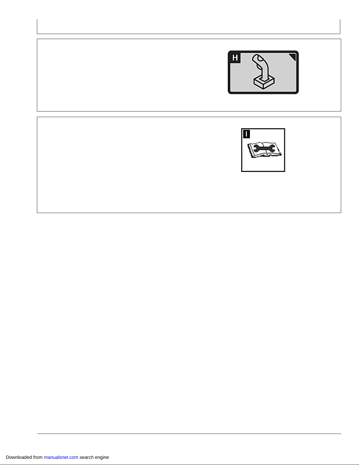
SprayStar System
AUXILIARY CONTROLS softkey—Input Device, Input,
Assigned, Function, Implement
DIAGNOSTICS softkey
READING tab—Unswitched Voltage, Switched Voltage,
CAN High Voltage (Vehicle Bus), CAN Low Voltage
(Vehicle Bus), CAN High Voltage (Implement Bus), CAN
Low Voltage (Implement Bus), Operation Hours, Radar
Sensor Input, Implement Switch Status, Card Door Status,
Card Present, CCD Status, RS232 #1 Status, RS232 #2
Status, Speed Source, Software Part Number, Software
Version Number, Hardware Part Number, Hardware Serial
Number
TEST tab—Color Test, Touchscreen Test, Touchscreen
Calibration
PC8691 —UN—16OCT07
AUXILIARY CONTROLS softkey
OUO6092,00011D4 1931MAR084/5
PC8683 —UN—05AUG05
DIAGNOSTICS softkey
ABOUT tab—Copyright information, Build Initiated, Build
Machine, Application Software Build, P/N, S/N, CPLD
OUO6092,00011D4 1931MAR085/5
Downloaded from manualsnet.com search engine
4011
122309
PN=93
Page 94

DISPLAY softkey
SprayStar System
Display Main
When display is initially installed in a vehicle, it will have a
default setting for all features. Operators have the ability
to change these settings to fit their needs. Once these
PC8841 —UN—30OCT05
settings are changed, they will be saved and retained
through each power cycle.
Continued on next page OUO6092,00010D5 1913NOV081/8
Downloaded from manualsnet.com search engine
4012
122309
PN=94
Page 95

SprayStar System
Go to MENU >> DISPLAY button >> DISPLAY softkey
PANEL DIM button allows operator to quickly darken
screen with one button push. When the operator engages
the panel dim feature the screen temporarily darkens
in order to reduce glare. Screen will resume normal
brightness when an alarm condition exists or when
operator touches screen.
PC8663 —UN—05AUG05
PC8654 —UN—05AUG05
PC8689 —UN—09AUG05
PC8684 —UN—09AUG05
MENU button
DISPLAY button
DISPLAY softkey
OUO6092,00010D5 1913NOV082/8
PANEL DIM button
OUO6092,00010D5 1913NOV083/8
NOTE: To exit Panel Dim, press any button
on display control.
BRIGHTNESS button can be changed by selecting PLUS
or MINUS button.
NOTE: Sync with Cab feature only functions on
selected vehicles.
Sync with Cab check box , when activated, allows display
to control all lights within vehicle cab. Deselecting check
box will allow only display to lighting to change with no
effect on other cab displays and lights.
4013
PC8685 —UN—09AUG05
BRIGHTNESS button
OUO6092,00010D5 1913NOV084/8
PC8686 —UN—09AUG05
Sync With Cab Check box
Continued on next page OUO6092,00010D5 1913NOV085/8
122309
PN=95
Downloaded from manualsnet.com search engine
Page 96

SprayStar System
DAYLIGHT/NIGHTLIGHT button allows operator to
quickly change screen with one button push. control.
Volume can be changed by selecting either + or button.
NOTE: Highlight color is defaulted to red at initial
powerup of display.
Highlight/Focus Color can be changed by selecting
desired color (red, blue, green).
PC8693 —UN—09AUG05
DAYLIGHT/NIGHTLIGHT button
OUO6092,00010D5 1913NOV086/8
PC8687 —UN—09AUG05
VOLUME button
OUO6092,00010D5 1913NOV087/8
PC8686 —UN—09AUG05
Highlight/Focus Color
OUO6092,00010D5 1913NOV088/8
Downloaded from manualsnet.com search engine
4014
122309
PN=96
Page 97

SprayStar System
Application Menu
Selecting the Menu Button on the display gives access
to the applications shown.
A—Menu Button
B—Layout Manager Button
C—Sprayer Application Button
D—Display Button
E—GreenStar2 Pro Button
F— Original GreenStar Monitor
Button
G—Message Center Button
N84875 —UN—29JUN09
OUO6092,0000218 1906JUL091/1
Downloaded from manualsnet.com search engine
4015
122309
PN=97
Page 98

SETTINGS softkey
SprayStar System
IMPORTANT: To reprogram to another language,
language being selected needs to be on data
card. If language file does not load properly,
reload software to data card.
NOTE: If vehicle loses battery power or if display
is disconnected from vehicle Time and Date
Settings will have to be reset.
The Settings screen contains three tabs:
REGIONAL tab
Country, Language, Numeric Format and Units can be
selected. Use dropdown boxes and select desired
measurements to be displayed on screen.
TIME AND DATE tab
Date and time can be changed, as well as time format.
GPS Sync can be selected to automatically set the time
using the time data coming from GPS receiver. When
this is selected, user should choose proper time offset,
which adjusted the GPS time data to correspond to your
time zone, to ensure correct local time. Time Sync will not
occur until GPS signal is acquired.
UNITS OF MEASURE tab
Users can customize units for a mix of metric and imperial
units.
PC8663 —UN—05AUG05
PC8654 —UN—05AUG05
PC8690 —UN—09AUG05
MENU button
DISPLAY button
SETTINGS softkey
OUO6092,0000D42 1907DEC061/1
Downloaded from manualsnet.com search engine
4016
122309
PN=98
Page 99

SprayStar System
DIAGNOSTICS softkey
The Diagnostics screen contains three tabs:
READINGS tab
•
TESTS tab
•
ABOUT tab
•
READINGS tab
This tab will display operating voltages, part numbers,
and hours of operation.
TESTS tab
This tab will allow the user to perform 3 different screen
calibrations—Color Test, Touchscreen Test, Touchscreen
Calibration.
The main function under the tests tab will be Touchscreen
calibration. Touchscreen calibration will be required when
the screen icon does not align with the area depressed.
This may be caused by normal wear and tear, age, certain
weather conditions, and contaminants on the screen
(chemicals, solvents, etc.).
Touchscreen Calibration:
1. Under the Touchscreen Calibration button a new
screen will appear with an X in the upper right corner.
2. Press the screen at the X and continue to follow the
X’s around the screen. Always press the screen
directly at the center of the X.
3. Several X’s will show up at various locations on the
screen.
4. Continue to press at the center of the X until complete.
Reset Touchscreen calibration will abort any saved
calibrations and allow the user to start over and perform a
new calibration.
Color Test:
Under the Test button, select the color test. The color
test will display 3 distinct colors on the display for
approximately 5 seconds. If you do not see 3 distinct
colors, contact your John Deere Dealer for service.
PC8663 —UN—05AUG05
PC8654 —UN—05AUG05
PC8683 —UN—05AUG05
MENU button
DISPLAY button
DIAGNOSTICS softkey
Touchscreen Test:
Under the Test button, select the Touchscreen Test. This
test will allow the user to identify a pixel problem on the
screen.
1. As you touch the screen, a sighting target will show
up on the area touched.
2. Continue to touch the screen around the area of
suspected pixel malfunction and see if the sighting
target appears.
If sighting target does not appear, contact your John
Deere Dealer.
ABOUT tab
This tab is basic display background display information.
OUO6092,0000D43 1901FEB071/1
Layout Manager
The Layout Manager provides the operator the ability to
display userdefined screens in the home page layout.
Once these screens are configured, the display will return
to the configuration anytime the Home softkey is pressed.
NOTE: Original GreenStar Monitor Mode is only available
in layout manager option A and F. Vehicle Bus is
only available in layout manager option A.
Downloaded from manualsnet.com search engine
PC9033 —UN—17APR06
Home Softkey
Continued on next page OUO6092,00000C8 1919AUG081/7
4017
122309
PN=99
Page 100

SprayStar System
Select Menu, then select Softkey I which is the Layout
Manager Option.
Press softkey A, then press the large red area in main
screen, this will bring you to the selection of programs to
operate in that defined red area. You will see that Layout
Manager A and F will have the largest selection of choices
and layouts available.
PC8663 —UN—05AUG05
PC8656 —UN—17NOV05
MENU button
OUO6092,00000C8 1919AUG082/7
Downloaded from manualsnet.com search engine
Continued on next page OUO6092,00000C8 1919AUG083/7
4018
PC8870 —UN—17NOV05
122309
PN=100
 Loading...