

Page 1
John Deere RTK Radio 450
OPERATOR'S MANUAL
John Deere RTK Radio 450
OMPFP10922 ISSUE J1 (ENGLISH)
DCYOMPFP10922
CALIFORNIA
Proposition 65 Warning
Diesel engine exhaust and some of its constituents
are known to the State of California to cause cancer,
birth defects, and other reproductive harm.
If this product contains a gasoline engine:
WARNING
The engine exhaust from this product contains
chemicals known to the State of California to cause
cancer, birth defects or other reproductive harm.
The State of California requires the above two warnings.
Additional Proposition 65 Warnings can be found in this manual.
John Deere Werke Zweibrücken
Worldwide Version
PRINTED IN U.S.A.
Page 2

Introduction
www.StellarSupport.com
NOTE: Product functionality may not be fully represented in this document due to product changes occurring after the time of printing. Read the
latest Operator's Manual and Quick Reference Guide prior to operation. To obtain a copy, see your dealer or visit www.StellarSupport.com
OUO6050,0000FB1 -19-10AUG10-1/1
092711
PN=2
Page 3

Contents
Page
Safety
Recognize Safety Information ............................ 05-1
Understand Signal Words...................................05-1
Follow Safety Instructions...................................05-1
Practice Safe Maintenance.................................05-2
Handle Electronic Components and
Brackets Safely ..............................................05-2
Prevent Electrical Shock and Fires..................... 05-3
Avoid Exposure to High Radio
Frequency Fields............................................05-3
Avoid Electrical Power Lines ..............................05-4
Safety Sign
Antenna Front View Decal..................................10-1
FCC NOTIFICATIONS TO USER
FCC NOTIFICATION ..........................................15-1
450 MHz RTK .....................................................15-1
COUNTRY USE RESTRICTIONS......................15-1
Licensing of John Deere RTK Radio 450
Licensing of John Deere RTK Radio 450 ........... 20-1
John Deere RTK Radio 450 Compatability.........20-1
RTK Base Station Setup
System Overview................................................25-1
Vehicle Receiver.................................................25-2
Base Station Setup.............................................25-3
Base Station Setup—Amplier Option
(USA and Canada only) .................................25-4
Base Station Setup—Dual Radio (USA
and Canada only)...........................................25-6
Radio Power Setting to Meet Licensed ERP...... 25-9
Page
RTK Radio 450 Performance
RTK Radio 450 Accuracy ...................................40-1
Radio Self Test ................................................... 40-1
Line of Sight........................................................40-3
Operation of Vehicle Next to Base......................40-4
EC Declaration of Conformity.............................40-4
GS3 Display SF3000—John Deere RTK Radio 450
RTK SoftKey .......................................................30-1
Screens Common to Standard
(869MHz, 900MHz) and RTK Radio 450 ....... 30-2
RTK Main Page ..................................................30-2
RTK Congure Page .......................................... 30-4
Diagnostic LEDs
Diagnostic LEDs................................................. 35-1
RTK Radio 450 LEDs .........................................35-1
Amplier LEDs (USA and Canada only)............. 35-2
Original Instructions. All information, illustrations and specications in this
manual are based on the latest information available at the time of publication.
The right is reserved to make changes at any time without notice.
COPYRIGHT © 2011
DEERE & COMPANY
Moline, Illinois
A John Deere ILLUSTRUCTION ® Manual
i
All rights reserved.
092711
PN=1
Page 4

Contents
ii
092711
PN=2
Page 5
Safety
Recognize Safety Information
This is a safety-alert symbol. When you see this symbol
on your machine or in this manual, be alert to the potential
for personal injury.
Follow recommended precautions and safe operating
practices.
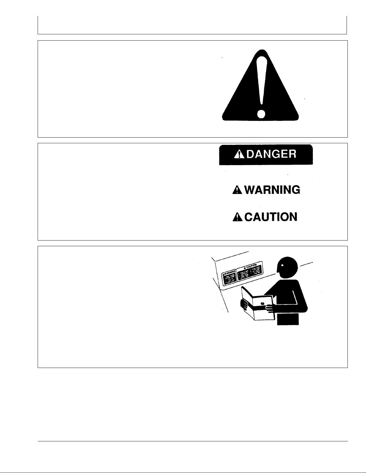
Understand Signal Words
A signal word—DANGER, WARNING, or CAUTION—is
used with the safety-alert symbol. DANGER identies the
most serious hazards.
DANGER or WARNING safety signs are located near
specic hazards. General precautions are listed on
CAUTION safety signs. CAUTION also calls attention to
safety messages in this manual.
T81389 —UN—07DEC88
DX,ALERT -19-29SEP98-1/1
Follow Safety Instructions
Carefully read all safety messages in this manual and on
your machine safety signs. Keep safety signs in good
condition. Replace missing or damaged safety signs. Be
sure new equipment components and repair parts include
the current safety signs. Replacement safety signs are
available from your John Deere dealer.
There can be additional safety information contained on
parts and components sourced from suppliers that is not
reproduced in this operator's manual.
Learn how to operate the machine and how to use controls
properly. Do not let anyone operate without instruction.
Keep your machine in proper working condition.
Unauthorized modications to the machine may impair the
function and/or safety and affect machine life.
TS187 —19—30SEP88
DX,SIGNAL -19-03MAR93-1/1
TS201 —UN—23AUG88
If you do not understand any part of this manual and need
assistance, contact your John Deere dealer.
DX,READ -19-16JUN09-1/1
05-1
092711
PN=5
Page 6
Safety
Practice Safe Maintenance
Understand service procedure before doing work. Keep
area clean and dry.
Never lubricate, service, or adjust machine while it is
moving. Keep hands, feet , and clothing from power-driven
parts. Disengage all power and operate controls to relieve
pressure. Lower equipment to the ground. Stop the
engine. Remove the key. Allow machine to cool.
Securely support any machine elements that must be
raised for service work.
Keep all parts in good condition and properly installed.
Fix damage immediately. Replace worn or broken parts.
Remove any buildup of grease, oil, or debris.
On self-propelled equipment, disconnect battery ground
cable (-) before making adjustments on electrical systems
or welding on machine.
On towed implements, disconnect wiring harnesses from
tractor before servicing electrical system components or
welding on machine.
Handle Electronic Components and Brackets Safely
Falling while installing or removing electronic components
mounted on equipment can cause serious injury. Use a
ladder or platform to easily reach each mounting location.
Use sturdy and secure footholds and handholds. Do not
install or remove components in wet or icy conditions.
If installing or servicing a RTK base station on a tower or
other tall structure, use a certied climber.
If installing or servicing a global positioning receiver mast
used on an implement, use proper lifting techniques and
wear proper protective equipment. The mast is heavy and
can be awkward to handle. Two people are required when
mounting locations are not accessible from the ground
or from a service platform.
TS218 —UN—23AUG88
DX,SERV -19-17FEB99-1/1
TS249 —UN—23AUG88
DX,WW,RECEIVER -19-24AUG10-1/1
05-2
092711
PN=6
Page 7
Prevent Electrical Shock and Fires
To prevent injury from electrical shock, always disconnect
power to the receiver, antenna, and amplier before
installing or servicing.
If installing with the power amplier option, prevent
electrical shock or re by using a 14 AWG heavy-duty
electrical cord with 15 amp rating suitable for outdoor use.
Understand and follow all local codes and regulations
when installing electrical equipment.
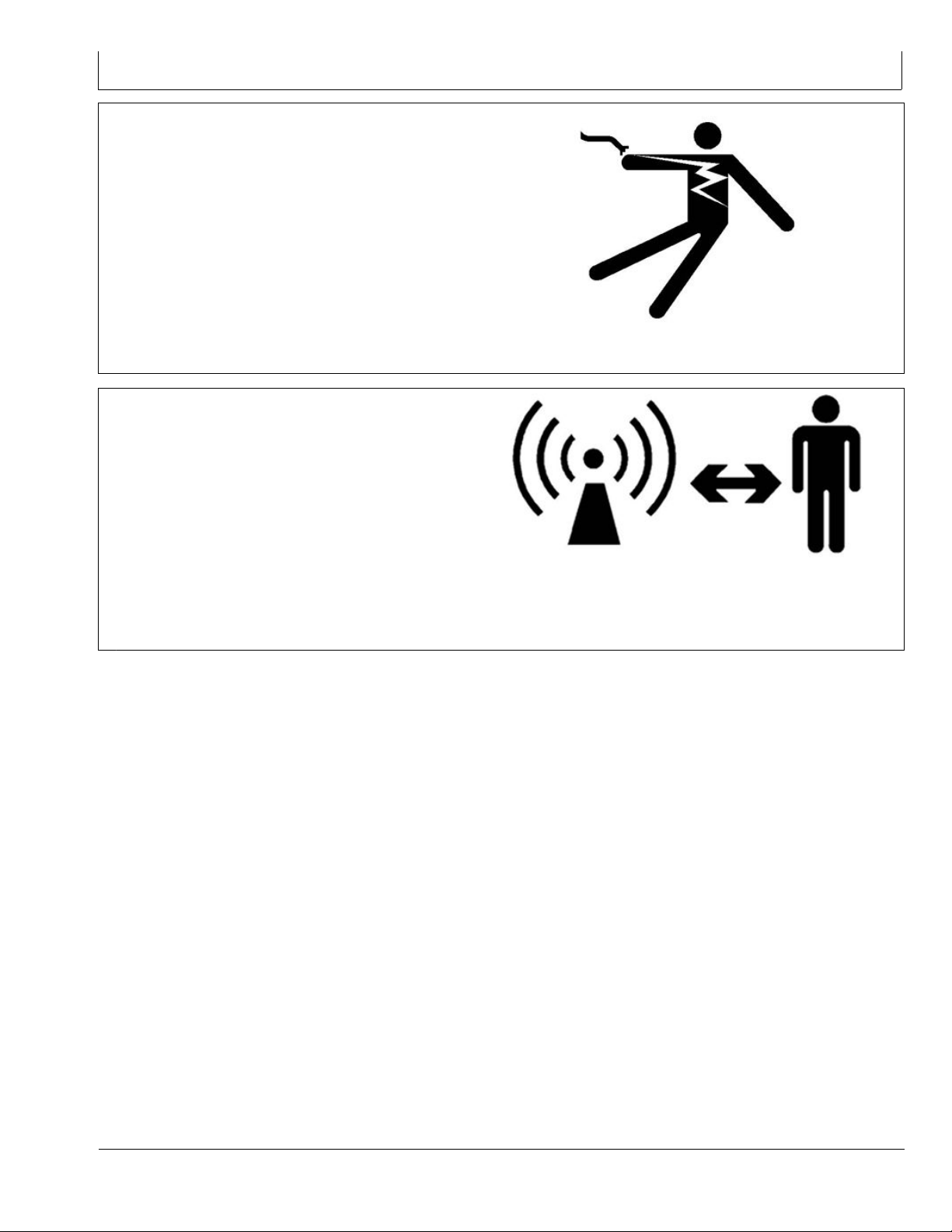
Avoid Exposure to High Radio Frequency Fields
Prevent injury from exposure to high radio frequency elds
at an RTK base station. Do not touch the antenna while
the system is transmitting. Always disconnect power to the
receiver, radio, and amplier before installing or servicing.
Safety
PC12631 —UN—04JUN10
JS56696,0000A47 -19-27JUL11-1/1
While the RTK base station amplier and radio are
operating together, stay at least 3.6 m (12 ft.) away from
the base antenna.
While using the base station radio without the amplier
option, stay at least 40 cm (16 in.) away from the radio
antenna.
PC12632 —UN—04JUN10
JS56696,0000A46 -19-27JUL11-1/1
05-3
092711
PN=7
Page 8
Safety
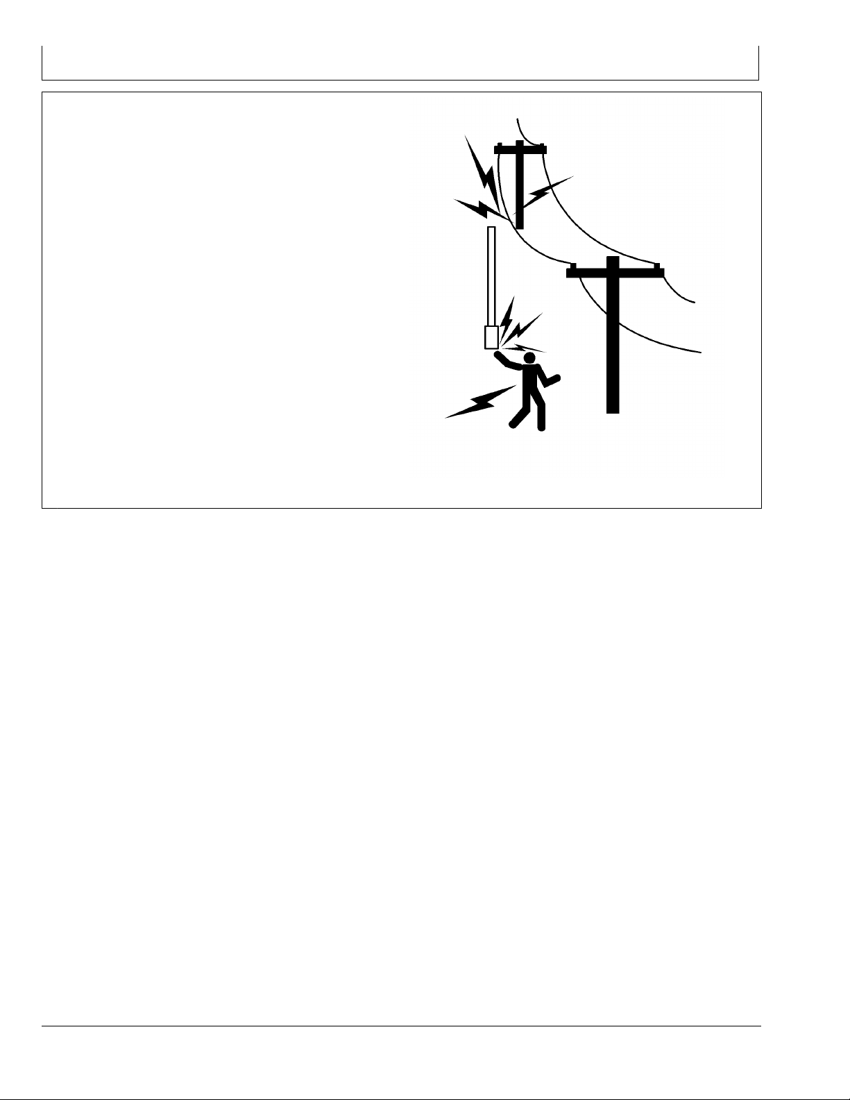
Avoid Electrical Power Lines
Watch for wires. Do not install the base antenna near
power lines. It may come into contact with low-hanging
electrical cables. This would result in the installer suffering
serious injury or death from electrocution.
PUPC000036 —UN—09DEC09
JS56696,00008AC -19-03JUN10-1/1
05-4
092711
PN=8
Page 9
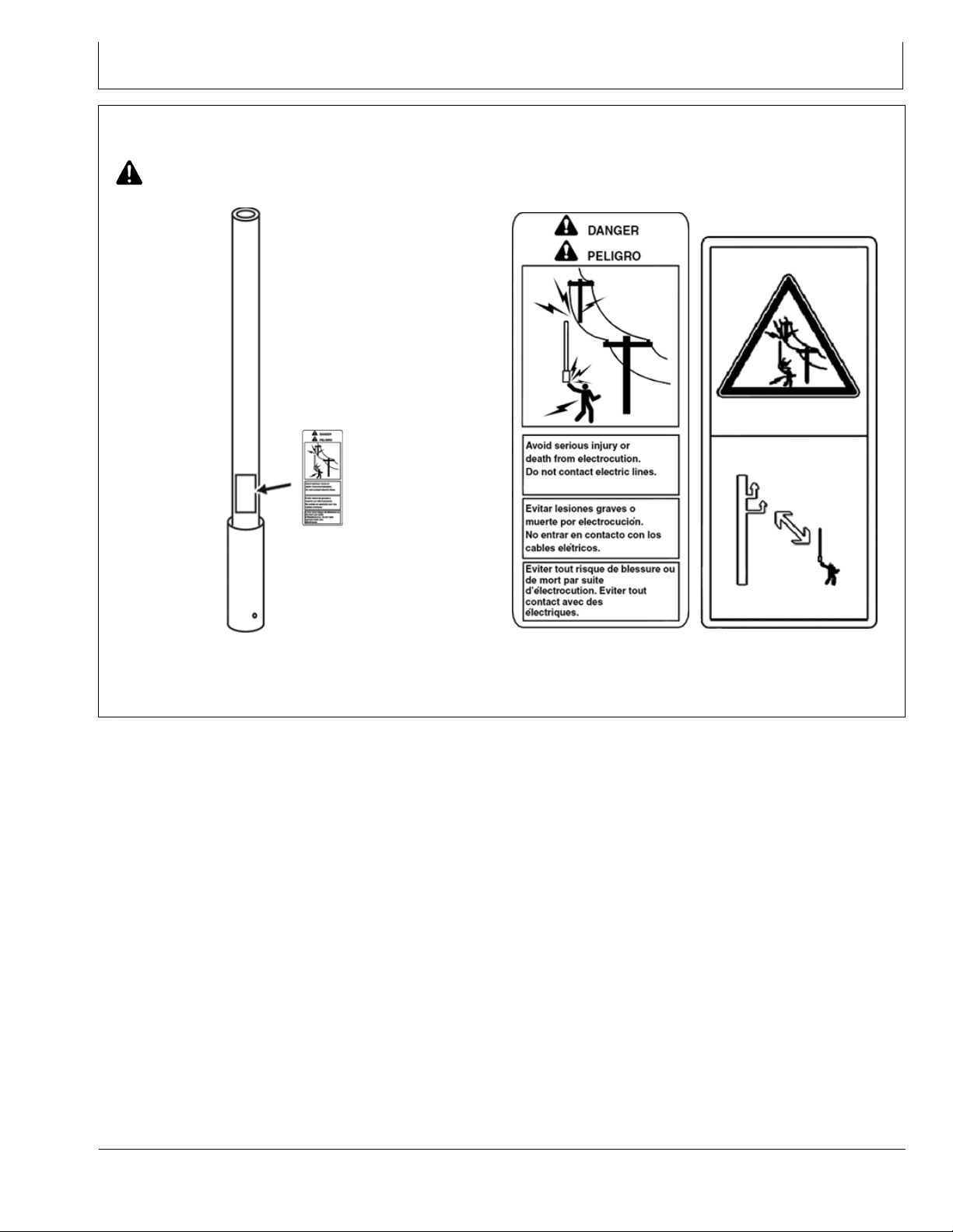
Antenna Front View Decal
CAUTION: To avoid serious injury or death
from electrocution. Do not come into contact
with electrical lines.
Safety Sign
Antenna Front View Decal Location
PUPC000037 —UN—10DEC09
USA, Canada, Australia and New
Zealand Antenna Decal
General Antenna Decal (except
for US, CA, NZ and AU)
DK01672,000014B -19-26JUL11-1/1
PC13795 —UN—25MAY11
10-1
092711
PN=9
Page 10

FCC NOTIFICATIONS TO USER
FCC NOTIFICATION
These devices comply with Part 15 of the FCC Rules
Operation subject to the following two conditions.
1. These devices may not cause harmful interference.
2. These devices must accept any interference received,
including interference that may cause undesired
operation.
450 MHz RTK
This equipment has been tested and found to comply with
the limits for a Class A digital device, pursuant to Part 15
of the FCC Rules. These limits are designed to provide
reasonable protection against harmful interference when
the equipment is operated in a commercial environment.
This equipment generates, uses, and can radiate radio
COUNTRY USE RESTRICTIONS
The John Deere RTK Radio 450 is designed to operate
on frequency ranges, the exact use of which differs from
one region and/or country to another. The user of the
radio modem must take care that the said device is not
operated without permission of the local authorities on
These devices must be operated as supplied by John
Deere Ag Management Solutions. Any changes or
modications made to these devices without the express
written approval of John Deere Ag Management Solutions
may void the user’s authority to operate these devices.
DK01672,0000136 -19-22JUL11-1/1
frequency energy and, if not installed and used in
accordance with the instruction manual, may cause
harmful interference to radio communications. Operation
of this equipment in a residential area is likely to cause
harmful interference in which case the user will be
required to correct the interference at the user’s expense.
DK01672,0000137 -19-22JUL11-1/1
frequencies other than those specically reserved and
intended for use without a specic permit. Refer to table
Radio Power Setting to Meet Licensed ERP in this OM.
IMPORTANT: Please contact your local radio
authorities for country specic regulations
and licensing
DK01672,0000108 -19-15JUL11-1/1
15-1
092711
PN=10
Page 11
Licensing of John Deere RTK Radio 450
Licensing of John Deere RTK Radio 450
The standard (869MHz, 900MHz) RTK product sold by
John Deere uses ISM band radios. These radios do not
require licensing by the end user. The radios are limited
to a specic frequency range and 1W/ 0.5W maximum
output power. While this system works for the majority of
applications, the reliability of the RTK link may become
limited when passing through trees and dense foliage.
The intent of RTK Radio 450 is to increase the range and
reliability of the RTK link. To overcome the attenuation
of adverse eld conditions, transmission power greater
than standard (869MHz, 900MHz) RTK is needed. While
there is some added benet from using a radio with lower
frequency and longer wavelength, the signal strength
is the dominant factor in the radio link reliability. To
legally transmit at a higher power, RTK Radio 450 uses
a licensed band radio. The end user of the licensed
band transmitting radio is responsible for obtaining and
maintaining a valid site license from the local spectrum
authorities. In RTK Radio 450 system, this requires a
license for each base station and repeater.
Vehicle radios in RTK Radio 450 system are not
transmitters. Since they only receive corrections from the
base or repeater, RTK Radio 450 vehicle radios do not
require a site license.
An end user can apply for the license by applying directly
to the local spectrum authority:
NOTE: Visit www.StellarSupport.com for license
request examples and links to Authority for
different countries.
that has been certied by the local frequency spectrum
authority to recommend and aid in the application for a
licenses. For a fee, these third party coordinators will
reduce the complexity and confusion of the application
process. However, the nal responsibility of the license
still resides with the end user.
Check www.StellarSupport.com for country specic
instructions on how to obtain a site license.
IMPORTANT: Please contact your local radio
authorities or partnering frequency coordinator
for region specic regulations and licensing.
License Renewal Scams
After being granted a license for RTK Radio 450 radio,
base station operators should be aware of license
renewal scams. Spectrum licenses are public record.
Other companies could retrieve licensee information
and then mail current license holders offers to prepare
applications for license renewal. The letters contain
warnings that there will be monetary penalties if the
licensee does not comply. These companies are not
afliated with government spectrum authorities. They are
taking advantage of the public record and the licensee’s
desire to comply with the law. Their intention is to charge
a “processing” fee on top of the actual amount that a
licensee would pay for renewal. While it is important to
not let your license expire, licensees should work directly
with their local spectrum authority or a certied frequency
coordinator. Internet searches of the companies involved
usually identify if the company is relevant.
An end user can also apply with the aid of a frequency
coordinator. A frequency coordinator is a private company
John Deere RTK Radio 450 Compatability
Base Station
StarFire iTC YES YES
StarFire 3000 + Glonass YES YES
StarFire 3000 + Glonass + Repeaters NO YES
IMPORTANT: If a Repeater is used in the John Deere
RTK Radio 450 network it’s recommended
to use StarFire 3000 receivers only for Base
Vehicle
StarFire
iTC
“Repeater in Network” function in the StarFire
setup - Congure RTK Network menu if a
StarFire iTC is in the network.
Station and Vehicles. Also uncheck the
Vehicle
StarFire
3000
DK01672,0000140 -19-25JUL11-1/1
DK01672,0000141 -19-25JUL11-1/1
20-1
092711
PN=11
Page 12

RTK Base Station Setup
System Overview
The John Deere RTK Radio 450 system consists of a
local base station permanently mounted on a structure
that transmits high accuracy corrections to the vehicle’s
StarFire™ receiver using RTK Radio 450 and an optional
amplier (only available in USA and Canada). The
StarFire™ receiver on the RTK equipped vehicle must
have a direct line of sight with the base station in order to
receive the RTK signal. While the higher transmission
power and longer wavelength of RTK Radio 450 aids
in the transmission through trees and foliage, it will not
penetrate through earth in hilly terrains.
Performance of the RTK correction is related to the
operating distance from the base station. When operating
beyond 20 km (12 mi.), degraded accuracy will occur and
it may take longer to initially acquire the RTK signal.
IMPORTANT: The standard (869MHz, 900MHz) RTK
system and RTK Radio 450 systems are not
compatible. Vehicles with RTK Radio 450
must receive corrections from a RTK Radio
450 attached to the base. Likewise, vehicles
with standard (869MHz, 900MHz) radios
installed must receive there corrections from
a base with a standard (869MHz, 900MHz)
radio installed. Different radio models can
not communicate with each other since they
transmit on different frequencies.
BA31779,00001CE -19-23MAY11-1/1
25-1
092711
PN=12
Page 13

Vehicle Receiver
RTK Receiver on Top of Cab
RTK Base Station Setup
PUPC000003 —UN—03DEC09
Wire Bracket on Top of Cab
PC13760 —UN—17MAY11
Position receiver with integrated RTK radio module is
located on top of machine.
Position receiver combines the global positioning signals
it receives with the RTK differential correction via the
radio link to provide accurate position information to the
GreenStar™ system.
The receiver has a dedicated operating mode (Vehicle
Mode). Refer to Operating Mode—RTK in Section
StarFire 3000 for setup of the receiver on vehicle.
IMPORTANT: The antenna must be installed before
the radio module is powered ON.
Avoid water intrusion by keeping the antenna
attached whenever possible.
Removing the antenna while powered may
damage the radio module.
The RTK Radio 450 system is only compatible with the
deluxe shroud. This may require a conversion bracket
for installation.
GreenStar is a trademark of Deere & Company
PC13782 —UN—19MAY11
Mannheim Tractor Conversion Bracket
DK01672,000012E -19-21JUL11-1/1
25-2
092711
PN=13
Page 14

RTK Base Station Setup
Base Station Setup
The base station is the most critical part of RTK system.
During installation, care must be taken to ensure the base
has problem-free operation. There are two issues that
are responsible for most problems with a base station:
Shading and Multipathing. If a base station experiences
one of these problems, it could be detrimental to your RTK
operation. These issues are shared with the standard
(869MHz, 900MHz) RTK system. Mitigation techniques
have already been documented in the standard StarFire
3000 – RTK manual that came with the StarFire receiver.
This manual provides detailed recommendations to
minimizing these errors.
Base station operating mode can be either Absolute
Survey Base Mode or Quick Survey Base Mode.
NOTE: Quick Survey Base Mode is for testing
purposes only. this mode can be used to test the
functionality without doing the 24h measurement
with Absolute Survey Base Mode.
Once you have installed the base station receiver,
installing the radio in a location to best maximize the
output, can be a challenge. Below are several options
currently available through John Deere.
Leave the RTK radio in its original conguration
•
attached directly behind the base station receiver.
Use PF80821 extension harness [92 m (300 ft.) in
•
length], or PFP10549 MRTK and iGuide harness (5 m),
or PFP10540 MRTK and iGuide harness (10 m), or
PFP10541 MRTK and iGuide harness (20 m), moving
the radio from the back of the base station receiver to an
elevated position, and running the harness in between.
NOTE: It is important to use the PF80821 harness
and grounding wire properly according to the
installation instructions. This harness has built
in protection for both your radio and receiver
for unwanted electrical transients developed
on the harness.The Maximum recommended
harness length is 92m (300ft).
IMPORTANT: The antenna must be installed before
the radio module is powered ON.
Avoid water intrusion by keeping the
antenna attached whenever possible.
Removing the antenna while transmitting
may damage the radio module.
IMPORTANT: If using coaxial cable between the
radio and the antenna, you need to use
the lowest-loss cable available or you may
suffer RTK radio link range issues.
Attach the RTK radio in a secured location and run
•
low-loss coaxial cable between the radio and the
antenna.
NOTE: When using this option, it may be necessary
to install a higher-gain antenna and/or the
optional amplier (USA and Canada only)
to compensate for loss.
John Deere RTK Radio 450 Specications
Model
Number
Country
Frequency
Range
Bandwidth
Options
Modulation
RF Baud,
12.5 kHz BW
Frequency
Channels
Output
Power
Sensitivity -108 dBm at BER 10^-3; -106 dBm at BER 10^-6
In/Out
Impedance
Operating
Voltage
Operating
Temperature
Out RF
Connectors
Control
Connector
PFA10094 PFA10095 PFA10096 PFA10097
Russia Ukraine EU, BY, KZ,
435-447
MHz
12.5 kHz
level 2 GFSK
9.6 kbps at L2
2800 at 12.5 kHz
0.2-2 W
50 ohm
9-15 V DC
-30 to 60° C
Female TNC
4-pin Deutsch
440-450
MHz
NZ
435-470
MHz
USA, AU,
Canada
435-470
MHz
Every RTK Radio 450 radio comes standard with whip
antenna that has a TNC connection.
John Deere RTK Radio 450 Whip Antenna
Specications
Model Number PF81464
Gain
Frequency Range 450-470 MHz
Impedance 50 ohm
VSWR
RF Connector
Length
Model Number PFP10612
Gain
Frequency Range 435-450 MHz
Impedance 50 ohm
VSWR
RF Connector
Length
2 dBi
< 2:1
Female N-Type
13.2 in. (33.5 cm)
1 dBi
< 2:1
Female N-Type
13.2 in. (33.5 cm)
Continued on next page DK01672,0000145 -19-25JUL11-1/2
25-3
092711
PN=14
Page 15

RTK Base Station Setup
John Deere RTK Radio 450 High Gain Antenna
Model Number PF81452
Gain
Frequency Range 435-470 MHz
Max Power
Impedance
VSWR
RF Connector
Length
Fiberglass Tube dia
Base Pipe
Wind Survival 100 MPH (161 km/h)
7 dBi
200 W (UHF)
50 OHMS
< 1.7:1
N-FEMALE
81 in (2 m).
2 in (5 cm)
11 in (28 cm) long, 2 3/8 in (6 cm)
dia
Base Station Setup—Amplier Option (USA
and Canada only)
CAUTION: Install and operate the amplier
safely. Read and follow PREVENT ELECTRICAL
SHOCK AND FIRES and AVOID EXPOSURE
TO HIGH RADIO FREQUENCY FIELDS in
the SAFETY section.
The primary reason for RTK Radio 450 is to provide
a more robust RTK data link. Signal strength is the
dominant factor in the link reliability and range. For areas
where there are trees and other foliage, John Deere offers
an optional in-line amplier.
Always mount the radio antenna vertically to make sure
that the RTK signal is radiating outwards. If the antenna is
at an angle, it may cause the data received at the vehicle
to be lower than expected.
NOTE: The RTK Radio 450 whip antenna, PF81464
(450-470 MHz) and PFP10612 (435-450 MHz),
looks similar to 900 MHz and 869 MHz RTK
whip antennas. To differentiate, it has a white or
green stripe near its tip. The white stripe labels
the 450 - 470 MHz antenna and the green stripe
labels the 435 - 450 MHz antenna.
DK01672,0000145 -19-25JUL11-2/2
The PF81443 amplier is a UHF RF power amplier
intended for use in RTK Radio 450 system. It is not
intended to be used with standard (869MHz, 900MHz)
RTK or any other applications. The amplier can deliver
RF power from 0 to 50 W proportional to the 0 to 2 W input
from RTK Radio 450. It covers a frequency range from
450 MHz to 470 MHz. This higher signal strength provides
greater range from the base and increased coverage in
areas with dense foliage and trees.
This amplier is inserted between the radio and the base
antenna. The amplier has been designed to function
outdoors attached to its mounting plate with sun shade.
Mount the amplier in an area where air can freely
circulate around it. If possible, mount in a location shaded
from direct sunlight.
Operation of the amplier inside an enclosure is not
recommended. Poor ventilation within the box can
cause the amplier to overheat. While this would not
PUPC000027 —UN—06DEC09
Amplier Assembly
permanently damage the amplier, it would cause it to
stop amplication. The output signal would no longer be
strong enough for the vehicles in the eld to receive.
Continued on next page DK01672,0000139 -19-22JUL11-1/2
25-4
092711
PN=15
Page 16

RTK Base Station Setup
450 MHz Amplier Specications (USA
and Canada only)
Model Number PF81443
Frequency Range 450-470 MHz
Input Power 0-2 W
Output Power
Current During Transmission
Nominal Voltage
Internal fuse
In/Out Impedance
Operating Voltage 11-15 V DC
Max Duty Cycle 100%
Operating Temperature -30 to 60° C
In RF Connector Female TNC
Out RF Connectors
Power Connector Amphenol (EcoMate C016
0-50 W
8 amp
13.8 V DC
15 amp
50 ohm
Female N-Type
20D003 110 12)
There are 3 connections located at the bottom of the
power amplier:
1. 12 VDC power input
2. RF input via TNC connector
3. RF output via N-Type connector
The connectors should only be nger-tight. Using tools can
over tighten and damage the RF and power connectors.
A 13.8 V power supply capable of providing a constant
10 amp to the amplier is required. Amplier operation
with insufcient voltage can lead to higher amplier
operating temperatures. Insufcient current can cause the
amplier to not amplify or only partially amplify the RF
signal. These conditions result in incomplete or no RTK
transmissions being received by the vehicle.
IMPORTANT: Make sure the antenna and coax
are attached before the amplier module is
powered ON or damage to the amplier could
PUPC000028 —UN—06DEC09
Amplier Connection Ports
occur. Do not remove the coax or antenna
while the amplier is powered ON. Avoid
water intrusion by keeping the connections
attached whenever possible.
Make sure the power connector is attached
and unpowered when handling the RF IN and
RF OUT connectors. The ground provided by
the power connector protects the amplier
against possible electrostatic discharge.
DK01672,0000139 -19-22JUL11-2/2
25-5
092711
PN=16
Page 17

RTK Base Station Setup
Base Station Setup—Dual Radio (USA and Canada only)
Dual Base Radio Cartoon
A—900MHz RTK Radio
B—RTK Radio 450 with Amplier
A single base station receiver can be used to support
both the standard 900MHz RTK and the RTK Radio 450
concurrently. An additional harness is required that splits
StarFire is a trademark of Deere & Company
25-6
PC13761 —UN—17MAY11
the RS232 correction stream from the StarFire™ receiver
into two.
Continued on next page DK01672,00000E7 -19-12JUL11-1/3
092711
PN=17
Page 18

A—StarFire™ Receiver
B—RTK Radio 450 Receiver and
Congure
A - StarFire™ Receiver
Terminal Detail
1 12 V Power
2
3
4
Tx (From SF)
Rx (To SF)
Gnd
RTK Base Station Setup
Dual Base RTK Harness Schematic
C—900MHz Radio Receiver Only
Terminal Detail
1 12 V Power
2
3 None
4
PUPC000030 —UN—07DEC09
C - 900 MHz Radio Receiver Only
Tx (From SF)
Gnd
B - RTK Radio 450 Receiver and Congure
Terminal Detail
1 12 V Power
2
3
4
Tx (From SF)
Rx (To SF)
Gnd
Continued on next page DK01672,00000E7 -19-12JUL11-2/3
25-7
092711
PN=18
Page 19

RTK Base Station Setup
The ability to use a single base station is a substantial
reduction in cost and maintenance. The drawback to this
method is that only one radio can be congured at a time.
A single RS232 port is used by the StarFire™ receiver
to communicate with an RTK radio. Two radios can
simultaneously receive RTK corrections from the receiver.
Unfortunately, the receiver can not process simultaneous
messages sent from the radios. The two radios send
different messages and interfere. To ensure that this
interference does not occur, the dual radio harness has
the radio send wire in only one branch.
To prevent network connection errors, a specic
procedure must be followed when conguring a base
station supporting two radios:
1. Connect the Dual Radio Harness to the StarFire™
Receiver.
2. Power the base station StarFire™ Receiver with only
standard 900MHz RTK radio connected to 4-wire
Deutsch connector. The receiver must have clear
view of the sky.
3. Once the receiver determines its position, congure
standard RTK radio Network ID and Radio Channel.
PUPC000007 —UN—03DEC09
4-Wire RTK Connector
4. Power down the base station StarFire™ Receiver.
5. Disconnect standard 900MHz RTK radio and then
connect RTK Radio 450 to the 4-wire Deutsch
connector.
6. Once the receiver determines its position and
recognizes the radio, congure RTK Radio 450 to
comply with the site license.
7. Power down the receiver.
8. With RTK Radio 450 still attached to the 4-Wire
Deutsch connector, connect the standard 900MHz
RTK radio to the 3-wire Deutsch connector.
9. Power the base station.
IMPORTANT: Do not attempt to change the radio
parameters while both radios are attached.
This can corrupt the conguration of 900 MHz
radio and may cause problems with rovers
liking to it. If this does occur, recongure the
radios with the process given above.
During normal operation, ensure that RTK Radio
450 is connected to the 4-wire connector and
that standard 900MHz RTK radio is connected
PC13762 —UN—17MAY11
3-Wire RTK connector
to the 3-wire connector. If the receiver detects
a standard 900MHz RTK radio, RTK Radio
450 link may be compromised. At its lowest
data speed, the RTK Radio 450 does not have
the capacity to transmit corrections at the
Standard 900MHz RTK radio.
The mandatory narrow bandwidth of the licensed band
radio results in a slower over-the-air baud rate because
Vehicles using 900Mhz will see fewer messages received
when using a dual radio base station as their correction
source. In a network with repeaters enabled the RTK
message rate will be further reduced.
DK01672,00000E7 -19-12JUL11-3/3
25-8
092711
PN=19
Page 20

RTK Base Station Setup
Radio Power Setting to Meet Licensed ERP
The RTK Radio 450 system has been designed to meet a
wide range of possible congurations. This gives the end
user the ability to optimize the system for their specic
location and application. The end user must obtain a
site license from the local spectrum authorities. It is the
end user’s responsibility to ensure that RTK Radio 450
system parameters are congured correctly. Frequency,
bandwidth, output power and antenna height must all
conform to the granted license.
The frequency and output power of the RTK Radio
450 are programmable by the StarFire™ receiver. The
available ranges are:
NOTE: Cable loss measured on LMR400 Cable.
0.3 dB connector loss estimate included for cables.
0.1 dB connector loss estimate for direct
connection of the antenna.
Radio Only Power Output
No Coax 15 ft. (4.6 m) 100 ft. (30.5 m) 200 ft. (61 m)
Radio
Output
Power
Watts
2.0 2.5 3.1
1.6 2.0 2.5
1.3 1.6 2.0
1.0 1.2 1.6
0.8 1.0 1.2
0.6 0.8 1.0
0.5 0.6 0.8
0.4 0.5 0.6
0.3 0.4 0.5
0.3 0.3 0.4
0.2 0.2 0.3
1dBi
Whip
2 dBi
Whip
7 dBi
Base
—
—
—
—
—
—
—
—
—
—
—
1dBi
Whip
2.1 2.6 8.3 1.4 1.8 5.8 0.9 1.2 3.6
1.7 2.1 6.6 1.2 1.4 4.6 0.7 0.9 2.9
1.3 1.7 5.3 0.9 1.2 3.6 0.6 0.7 2.3
1.0 1.3 4.2 0.7 0.9 2.9 0.5 0.6 1.8
0.8 1.0 3.3 0.6 0.7 2.3 0.4 0.5 1.4
0.7 0.8 2.6 0.5 0.6 1.8 0.3 0.4 1.2
0.5 0.7 2.1 0.4 0.5 1.4 0.2 0.3 0.9
0.4 0.5 1.7 0.3 0.4 1.2 0.2 0.2 0.7
0.3 0.4 1.3 0.2 0.3 0.9 0.1 0.2 0.6
0.3 0.3 1.0 0.2 0.2 0.7 0.1 0.1 0.5
0.2 0.3 0.8 0.1 0.2 0.6 0.1 0.1 0.4
2 dBi
Whip
Frequency 435 – 470 MHz
Frequency Resolution 6.25 kHz
Bandwidth 12.5 kHz
Radio Output Power
Amplier Output Power
0.2 to 2.0 W
5.0 to 50.0 W
When installing a base station, the total output power of
the system must be adjusted to comply with the granted
license. Cable losses, connection losses and the antenna
gain must be considered when calculating the total system
output power. The radio output power is congured using
GreenStar 3 System™ Display. Equivalent Radiated
Power (ERP) of the radio should be adjusted to ensure
that the total RTK Radio 450 system output power
complies with the license granted by the local spectrum
authority. The following tables can be used to determine
the appropriate setting.
NOTE: The use of an Amplier is only permitted
in the USA and Canada.
7 dBi
Base
1 dBi
Whip
2 dBi
Whip
7 dBi
Base
1dBi
Whip
2 dBi
Whip
7 dBi
Base
Radio and Amplier Power Output (USA and Canada only)
No Coax 15 ft. (4.6 m) 100 ft. (30.5 m) 200 ft. (61 m)
Radio
Output
Power
Watts
2.0 61.5 77.4
1.6 48.9 61.5
1.3 38.8 48.9
1.0 30.8 38.8
0.8 24.5 30.8
0.6 19.5 24.5
0.5 15.5 19.5
0.4 12.3 15.5
0.3 9.7 12.3
0.3
0.2 6.1
GreenStar 3System is a trademark of Deere & Company
1 dBi
Whip
7.7
2 dBi
Whip
9.7
7.7
7 dBi
Base
—
—
—
—
—
—
—
—
—
—
—
1dBi
Whip
52.4 65.9 208.4 36.2 45.6 144.2 22.9 28.8 91.0
41.6 52.4 165.6 28.8 36.2 114.5 18.2 22.9 72.3
33.0 41.6 131.5 22.9 28.8 91.0 14.4 18.2 57.4
26.2 33.0 104.5 18.2 22.9 72.3 11.5 14.4 45.6
20.8 26.2 83.0 14.4 18.2 57.4 9.1 11.5 36.2
16.6 20.8 65.9 11.5 14.4 45.6 7.2 9.1 28.8
13.2 16.6 52.4 9.1 11.5 36.2
10.4 13.2 41.6 7.2 9.1 28.8 4.6
8.3 10.4 33.0
6.6 8.3 26.2 4.6
5.2 6.6 20.8 3.6 4.5 14.4 2.3 2.9 9.1
2 dBi
Whip
7 dBi
25-9
Base
1dBi
Whip
5.7
2 dBi
Whip
7.2 22.9 3.6 4.6 14.4
5.7
7 dBi
Base
18.2 2.9 3.6 11.5
1 dBi
Whip
5.7
2 dBi
Whip
7.2 22.9
5.7
DK01672,000014A -19-25JUL11-1/1
7 dBi
Base
18.2
092711
PN=20
Page 21

GS3 Display SF3000—John Deere RTK Radio 450
RTK SoftKey
RTK Radio 450 is supported by VI displays. These include
GreenStar™ 3 2630 Display, GreenStar™ 2 2600 Display
and SDUA. Conguration with the original GreenStar™
Display is not supported.
Allows for setup and display of both standard (869MHz,
900MHz) RTK and RTK Radio 450 information:
Operating Mode
•
RTK Network Conguration
•
Base Station Data
•
Radio Data
•
The RTK Radio 450 shares the same activation as
standard (869MHz, 900MHz) RTK. The receiver
automatically detects which radio is connected at start-up
and adjusts its screens for the appropriate radio when
the softkey is pressed.
RTK Radio 450 can be operated in three modes:
Vehicle
•
Quick Survey Base (for testing purposes only)
•
Absolute Base
•
IMPORTANT: Any time the radio is recongured
or changed, power must be cycled at the
GPS receiver before continuing.
Vehicle Mode Select this mode if the receiver is on a
vehicle.
Quick Survey Base Mode Select for testing purposes
only. This mode can be used to test the functionality
without doing the 24h measurement with Absolute Survey
Base Mode. Regarding your licence for each base station,
the usage of the “Quick Survey” setup is only permitted at
the dedicated location as per licence agreement stated.
Absolute Survey Base Mode Select if exact location of
guidance tracks need to be stored for future guidance
applications without relying on visual reference for track
GreenStar is a trademark of Deere & Company
PC8663 —UN—05AUG05
PC13006 —UN—08NOV10
PC8681 —UN—05AUG05
position to align using Shift Track feature. Track 0 must
be stored using Current Track 0 in Guidance Setup – Set
Track 0 in order to follow previously used tracks. Absolute
Base Mode requires 24 hour self survey to be conducted
on location before rst use. After survey is completed,
base station will then transmit corrections. If base station
is moved to another position and then returned to original
surveyed position, it is very important that base station is
mounted in exact same position. Any difference between
original surveyed position and mounted position will
result in offset of corrected position. For this reason, it
is important to mount receiver to a xed position like a
building or post mounted in concrete.
OFF Mode This mode disables all RTK functionality in
receiver. RTK Operating Mode must be OFF for normal
SF1 or SF2 operation on SF2 licensed receiver.
MENU Button
StarFire iTC Button
RTK Softkey
DK01672,000014C -19-26JUL11-1/1
30-1
092711
PN=21
Page 22

GS3 Display SF3000—John Deere RTK Radio 450
Screens Common to Standard (869MHz,
900MHz) and RTK Radio 450
When RTK is in the OFF mode, the main pages are
common between the two systems. The details of these
particular pages are provided in the StarFire 3000 and
RTK Operator’s Manual. This manual was provided with
the purchase on an SF3000 receiver. When in VEHICLE
or BASE mode, the pages for RTK Radio 450 system vary
slightly from the pages for standard (869MHz, 900MHz)
RTK system.
There is single RTK activation that provides access to
both standard (869MHz, 900MHz) RTK and RTK Radio
450. The difference between the two systems is the radio
hardware. After power is supplied, the receiver links up to
the attached radio and shows the relevant screens.
The Rover Access List currently used for standard
(869MHz, 900MHz) RTK is unchanged. When upgrading
RTK Main Page
IMPORTANT: Base station receiver and vehicle
receiver must be setup before operating RTK.
See RTK Base Station Setup Section.
NOTE: Check that base station and vehicle have
same Frequency, and Network ID.
to RTK Radio 450, previous lists remained stored in the
receiver. The methods of adding, editing and deleting
Rover receiver serial numbers remains unchanged.
Several other features in standard (869MHz, 900MHz)
RTK are also provided unchanged in the RTK Radio 450:
RTK-x
•
Optimized shading
•
Radio self test page
•
Absolute Base Coordinate Setup
•
TCM Calibration
•
NOTE: The John Deere RTK Radio 450 is
accessible for conguration when the StarFire
has GPS reception.
DK01672,00000EA -19-12JUL11-1/1
RTK Main—Vehicle
The majority of the diagnostics and controls are the same
as standard (869MHz, 900MHz) RTK on the RTK Main –
vehicle screen. Three items have been modied on the
RTK Main Page for RTK Radio 450.
Select: MENU Button >> StarFire 3000™ Button >>
RTK Softkey >> OPERATING MODE drop-down box >>
VEHICLE
A—The Radio ID control has
been replaced with the
Radio Frequency (MHz)
StarFire iTC is a trademark of Deere & Company
PC13856 —UN—10AUG11
RTK Main--Vehicle
Continued on next page DK01672,000013B -19-22JUL11-1/2
30-2
092711
PN=22
Page 23

GS3 Display SF3000—John Deere RTK Radio 450
RTK Main—Base Station
The Quick Survey Base and Absolute Base versions of
the RTK Main screens also display the frequency of the
radio link.
NOTE: The Quick Survey Base Mode is for testing
purposes only. This mode can be used to test the
functionality without doing the 24h measurement
with Absolute Survey Base Mode. Regarding
your licence for each base station, the usage of
the “Quick Survey” setup is only permitted at the
dedicated location as per licence agreement stated.
PC13857 —UN—13JUL11
RTK Main Vehicle (Quick Survey Base)
30-3
PC13858 —UN—13JUL11
RTK Main Vehicle (Absolute Base)
DK01672,000013B -19-22JUL11-2/2
092711
PN=23
Page 24

GS3 Display SF3000—John Deere RTK Radio 450
RTK Congure Page
The frequency and power settings for standard (869MHz,
900MHz) RTK are xed to comply with ISM band
requirements. For RTK Radio 450, these settings can
be controlled and are the responsibility of the end user.
Besides the Network ID on the RTK Main screen, there
are four parameters that manage the radio link between
the vehicle and Base: Radio Frequency, Bandwidth, Data
Rate and Power.
The Operation Mode provides the setup for Absolute
Base, Quick Survey Base, Vehicle or to shut RTK off.
The Radio Frequency is the center frequency of the link
shared between the Base and Rover.
The Network ID for base station and vehicle receiver
must match. If more than one base station with the same
Network ID numbers are within range, vehicle may lock
on to either one of the base stations. to prevent this from
happening, be sure to use unique network ID.
The Repeater in Network check box needs to be checked
if a repeater is in the network setup.
PC13859 —UN—12JUL11
Congure Radio Screen
Press: MENU Button >> StarFire3000™ Button >> RTK
Softkey >> Radio Congure Button
The output power control is only displayed when the
receiver is set to Quick Survey Base or Absolute base
Operating Modes. When the receiver is set as a Vehicle,
the radio output power is not visible since it is a receiver
only.
StarFire iTC is a trademark of Deere & Company
When a valid set of parameters is entered, a conrmation
screen will pop-up reminding the user not to vary from the
parameters designated in the license.
The RTK Radio 450 system is capable of operating over
a wide range of frequency and power settings. Since
the nal license parameters granted to the customer is
unknown to the manufacturer, this system exibility exists
to enable use by a large range of customers and markets.
The end user has the responsibility of conguring the
system parameters to meet the license granted them
by the local spectrum authority. Frequency, and output
power (if a base or repeater) will be designated by the
local license, and the base must be set to comply with
these specications.
A—Operation Mode
B—Network ID
C—Radio Frequency
D—Power
E—Repeater in Network
The cancel button disregards any input to the Radio
Congure screen and returns the user to the RTK Main
page.
DK01672,000013C -19-22JUL11-1/3
NOTE: See Operator’s manual regarding radio frequency
and power settings. Ensure radio settings are
consistent with local licensing requirements.
See users manual regarding radio frequency
and power settings.
30-4
PC13862 —UN—12JUL11
Continued on next page DK01672,000013C -19-22JUL11-2/3
092711
PN=24
Page 25

GS3 Display SF3000—John Deere RTK Radio 450
When the return button is pressed, verication is made on
the input radio parameters. If the combination inputs are
invalid, a pop-up screen will appear to communicate this.
NOTE: Conguration Unsuccessful.
PC13861 —UN—13JUL11
Conguration Unsuccessful
DK01672,000013C -19-22JUL11-3/3
30-5
092711
PN=25
Page 26

Diagnostic LEDs
Diagnostic LEDs
A key aid to gain insight into the working state of the RTK
Radio 450 system are the LEDs on both the RTK radio
RTK Radio 450 LEDs
There are three radio LEDs. They can be seen after the
radio has been powered. They are viewed through a
small window on the front of the radio.
The LEDs can be used to determine
□ Is the radio powered?
□ Is the radio congured as a Base Station or a vehicle?
□ Is the radio searching or linked?
□ Is the radio in conguration mode?
The radio enters conguration mode when parameters are
being read/set or when diagnostics are being retrieved.
While in congure mode, the radio does not transmit or
receive communications.
The meanings of the radio LED states are provided in the
table below.
and the in-line amplier (USA and Canada only). These
diagnostic lights can be used during setup, maintenance
and troubleshooting.
DK01672,00000F2 -19-13JUL11-1/1
PC13863 —UN—13JUL11
LED Window
A—LED Window
DK01672,0000174 -19-09AUG11-1/2
Radio LEDs Table
35-1
PC13864 —UN—13JUL11
DK01672,0000174 -19-09AUG11-2/2
092711
PN=26
Page 27

Diagnostic LEDs
Amplier LEDs (USA and Canada only)
There are four amplier LEDs. They are located on the
side of the amplier.
The LEDs can be used to determine
□ Is the amplier powered?
□ Is there an internal failure?
□ Is the radio signal being amplied?
□ Is the amplier setup causing it to overheat?
□ Is the antenna or its connection path faulty?
The LEDs operate in two states: Start Up and Operation.
After the amplier is initially powered, the amplier
strobes through each LED sequentially. This rapid
ashing sequence indicates that the internal rmware test
sequence is initiated. It checks the power to the unit and
the integrity of internal components.
The outcome of a successful startup test sequence results
in only the PWR LED on. The outcome of an unsuccessful
startup sequence results in the PWR LED and any of the
red LEDs on. These red LEDs indicate a failure.
During normal operation after a successful startup, each
amplier LED has a specic meaning.
Power LED Indicates that the amplier has DC power.
TX LED Indicates that an RF signal is being actively
amplied and transmitted. This light blinking indicates
normal function.
O/T LED Indicates that the unit has exceeded its internal
temperature limits. When this light is on, the unit will
cease amplication. This allows the unit to cool and
prevents permanent damage.
PUPC000031 —UN—07DEC09
Amplier LED
VSWR LED Indicates that the antenna path is faulty.
When this light is on, the unit will cease amplication. This
prevents the output power from being reected back into
the amplier and causing permanent damage.
DK01672,000010A -19-15JUL11-1/1
35-2
092711
PN=27
Page 28

RTK Radio 450 Performance
RTK Radio 450 Accuracy
The accuracy of RTK Radio 450 is the same as standard
(869MHz, 900MHz) RTK. The UHF link is more robust,
but the content sent by the StarFire RTK™ base to the
vehicle is identical.
StarFire RTK™ delivers 1 in. repeatable accuracy. RTK
accuracy is expressed as an absolute value (without +/-)
StarFire RTK is a trademark of Deere & Company
Radio Self Test
A Radio Self Test can be performed in the StarFire 3000
Diagnostics menu.
Select: MENU Button (A)>> StarFire 3000™ Button>>
Diagnostics Softkey (B) >> Radio Softkey (C) >> Start
Button (D).
A—Menu Button
B—Diagnostics Softkey
C—Radio Selftest tab
D—Start
because RTK performance is not subject to GPS drift over
time. RTK accuracy levels are described on a static basis
measured at the vehicle receiver, 68 percent of the time,
within 12 mi. (20 km) line of sight with the base station,
assuming unobstructed view of the sky, favorable PDOP,
and correct base station setup.
DK01672,00000F7 -19-13JUL11-1/1
PC13865 —UN—13JUL11
StarFire is a trademark of Deere & Company
When the test is running the screen changes. Number of
updates shows how many times the test is performing.
The other values show the distance from the radio to the
base or repeater station where it’s receiving the signal,
the number of disconnects, radio temperature, antenna
reected power, average noise and signal level and the
overall receive rate.
In order to stop the Radio Self Test press the End button
(A).
A—End Button
DK01672,000014D -19-26JUL11-1/3
PC13866 —UN—13JUL11
Radio Self Test
Continued on next page DK01672,000014D -19-26JUL11-2/3
40-1
092711
PN=28
Page 29

RTK Radio 450 Performance
The result of the last performed test is shown on the Radio
Self Test main screen.
Number of Updates:
•
Indicates how many times the Radio Self Test was
performed.
Radio Distance:
•
Indicates the distance in meters between the selected
radio (vehicle) and the radio to which the selected
radio is directly linked (Base/Repeater). It is typically
accurate to within 30 meters for distances over one Km
(0.6 miles). This calculation is performed by the radios
independent of the GPS receivers.
Number of Disconnects:
•
Indicates how many times a disconnect occurred during
this test.
Radio Temperature:
•
Shows the radio temperature.
Antenna Reected Power:
•
A measurement of the transmitted power reected
back into the transceiver from mismatched antennas or
cables, or loose connections between the transceiver
and antenna.
Average Noise Level:
•
The average noise level indicates the average power of
background noise and interference at the transceiver.
Ideally, noise level value should be greater than 120
and the difference between the average signal level and
average noise level should be 26 dB or more. Noise
levels signicantly higher than this are in indication
of a high level of interference that may degrade the
performance of the link.
Radio Self Test Main
Average Signal Level:
•
The average signal level indicates the average power of
the received signal for the attached radio. For a reliable
link, the average signal level should be between 35 and
106. The difference between the average signal level
and the average noise level should also be at least 26
dB.
DK01672,000014D -19-26JUL11-3/3
PC13867 —UN—13JUL11
40-2
092711
PN=29
Page 30

RTK Radio 450 Performance
Line of Sight
Line of sight is the direct path between two points,
free of obstacles. For the RTK application, this is the
line between the base and vehicle antennas. Typical
obstructions include:
Trees and foliage
•
Buildings or other man-made objects
•
Terrain variation, such as hills or valleys
•
Curvature of the Earth
•
The higher RF power of RTK Radio 450 will reduce
attenuation due to plants and small variations in terrain.
Blockage due to man-made objects can be reduced
through planning of the base antenna location. Similar
to analysis performed to locate the StarFire™ receiver
installation, the transmitting antenna should be located
away from nearby obstructions.
To deal with obstructions away from the base, small terrain
variations and the curvature of the Earth, the antenna
should be placed as high as possible. The local spectrum
authority will limit the range and potential interference of
the base station signal by setting a maximum power and
maximum antenna height. End users should install their
base antenna to the maximum height allowed for best
performance.
PC9393 —UN—23OCT06
In order to maintain a good RTK Radio link, the antenna
must be mounted high enough to radiate over the earth’s
curvature and any obstacles. As shown in the gure, the
curve of the earth can block the signal from the RTK link.
If the radiating base station radio antenna is mounted too
low, the broadcasting range will be drastically reduced.
StarFire RTK™ retains its published accuracy to 12 mi.
(20 km). If consistent with the granted site license, it is
recommended that antennas are mounted ≥ 30 m (100
ft.) to ensure the full range of coverage. The table below
relates the base antenna height to the line-of-sight to the
base radio horizon.
Base
Base Height
ft. mi. m km
148 16.3 45 26.3
131 15.4 40 24.8
125 15.0 38 24.2
115 14.4 35 23.2
98 13.4 30 21.5
82 12.2 25 19.6
66 10.9 20 17.6
49 9.4 15 15.2
33 7.7 10 12.4
20 6.0 6 9.6
10 4.2 3 6.8
5 3.0 1.5 4.8
Station
Radio
Horizon
Base
Height
Base
Station
Radio
Horizon
Line of
Sight
Strong
Good
Marginal
Poor
Antenna Height
RTK Shared Base Station: Antenna Height
StarFire is a trademark of Deere & Company
StarFire RTK is a trademark of Deere & Company
Continued on next page BA31779,00001BF -19-18MAY11-1/2
40-3
092711
PN=30
Page 31

RTK Radio 450 Performance
Operation of Vehicle Next to Base
Depending on the base station setup, operation of
vehicles directly under or next to the base may be limited.
The RTK Radio 450 system has both higher power and
higher signal sensitivity than standard (869MHz, 900MHz)
RTK. A consequence of this is that radio signals in the
for the receiving radios. For base stations that serve
vehicles at both ≥20 km and ≤ 1 km from the base, it
may be necessary to add inline RF attenuators to the
rovers operating directly under the base. Attenuator
specications: RF load of 15 dBm, capable of 2W, inline
female TNC to male TNC.
immediate vicinity of the transmitter may be too strong
EC Declaration of Conformity
Deere & Company
Moline, Illinois U.S.A.
The undersigned hereby declares that:
Product: John Deere RTK Radio 450
Part Number: PFA10096
fullls all relevant provisions and essential requirements of the following directive(s):
Directive Number
Radio and Telecommunications Terminal
Equipment Directive (R&TTE)
The product is in conformity with the following standards and/or other normative documents:
EN 60950-1: 2006
EN 60950-22: 2006
ETSI EN 301 489-1: 2008 (v.1.8.1)
ETSI EN 300 113-1: 2009 (v.1.6.2)
ETSI EN 300 113-2: 2009 (v.1.4.2)
Notied body involved: Nemko AS
Gåsevikveien 8
2027 Kjeller, Norway
Identication mark: 0470
1999/5/EC Annex IV (Notied body)
BA31779,00001D7 -19-23MAY11-1/1
Certication Method
Name and address of the person in the European Community authorized to compile the technical construction le:
Brigitte Birk
Deere & Company European Ofce
John Deere Strasse 70
Mannheim, Germany D-68163
EUConformity@JohnDeere.com
Place of declaration: Kaiserslautern, Germany Name: Aaron M. Senneff
Date of declaration: 18 May 2011 Title: Engineering Manager, John Deere Intelligent Solutions
Manufacturing unit: John Deere Intelligent
Solutions Group
PC14001 —UN—24AUG11
Group
JS56696,0000A51 -19-24AUG11-1/1
40-4
092711
PN=31
Page 32

RTK Radio 450 Performance
40-5
092711
PN=32
Page 33

Index
Page
A
Absolute Base Page, RTK Main ................................. 30-2
Accuracy..................................................................... 40-1
Antenna Front View Decal.......................................... 10-1
B
Base Station Setup..................................................... 25-3
Amplier Option ...................................................... 25-4
Dual Radio.............................................................. 25-6
Base Station Setup - Amplier Option........................ 25-4
Base Station Setup—Dual Radio ............................... 25-6
Base Station, RTK Main ............................................. 30-2
C
Common Screens....................................................... 30-2
Congure Page, RTK ................................................. 30-4
D
Decal .......................................................................... 10-1
Diagnostic................................................................... 35-1
Diagnostic LEDs......................................................... 35-1
Page
RTK Softkey ............................................................... 30-1
RTK Vehicle Page ...................................................... 30-2
S
Safety Sign................................................................. 10-1
Screens Common to Standard and RTK
Radio 450 ................................................................. 30-2
Setting to Meet Licensed ERB.................................... 25-9
Sight ........................................................................... 40-3
Softkey........................................................................ 30-1
Standard and RTK Radio 450 Common Screens....... 30-2
System Overview........................................................ 25-1
V
Vehicle Next to Base .................................................. 40-4
Vehicle Page, RTK Main............................................. 30-2
Vehicle Receiver......................................................... 25-2
L
Line of Sight................................................................ 40-3
O
Operation of Vehicle Next to Base.............................. 40-4
Q
Quick Survey Base Page, RTK Main.......................... 30-2
R
Radio Power Setting................................................... 25-9
Radio Power Setting to Meet Licensed ERB.............. 25-9
RTK
Base Station Setup ................................................. 25-3
Base Station Setup - Amplier Option .................... 25-4
Base Station Setup—Dual Radio............................ 25-6
Main Page............................................................... 30-2
Main Page-Absolute Base ...................................... 30-2
Main Page-Base Station ......................................... 30-2
Main Page-Quick Survey Base............................... 30-2
Main Page-Vehicle .................................................. 30-2
RTK Radio 450 and Standard Common Screens ... 30-2
Softkey.................................................................... 30-1
System Overview.................................................... 25-1
Vehicle Receiver ..................................................... 25-2
RTK Accuracy............................................................. 40-1
RTK Congure Page .................................................. 30-4
RTK Main Page .......................................................... 30-2
Index-1
092711
PN=1
Page 34

Index
Index-2
092711
PN=2
Page 35

John Deere Service Literature Available
Technical Information
Technical information can be purchased from John Deere.
Some of this information is available in electronic media,
such as CD-ROM disks, and in printed form. There are
many ways to order. Contact your John Deere dealer.
Call 1-800-522-7448 to order using a credit card. Search
online from http://www.JohnDeere.com. Please have
available the model number, serial number, and name of
the product.
Available information includes:
PARTS CATALOGS list service parts available for your
•
machine with exploded view illustrations to help you
identify the correct parts. It is also useful in assembling
and disassembling.
OPERATOR’S MANUALS providing safety, operating,
•
maintenance, and service information. These manuals
and safety signs on your machine may also be available
in other languages.
OPERATOR’S VIDEO TAPES showing highlights of
•
safety, operating, maintenance, and service information.
These tapes may be available in multiple languages
and formats.
TECHNICAL MANUALS outlining service information
•
for your machine. Included are specications, illustrated
assembly and disassembly procedures, hydraulic oil
ow diagrams, and wiring diagrams. Some products
have separate manuals for repair and diagnostic
information. Some components, such as engines, are
available in separate component technical manuals
FUNDAMENTAL MANUALS detailing basic information
•
regardless of manufacturer:
- Agricultural Primer series covers technology in farming
and ranching, featuring subjects like computers, the
Internet, and precision farming.
- Farm Business Management series examines
“real-world” problems and offers practical solutions
in the areas of marketing, nancing, equipment
selection, and compliance.
- Fundamentals of Services manuals show you how to
repair and maintain off-road equipment.
- Fundamentals of Machine Operation manuals
explain machine capacities and adjustments, how to
improve machine performance, and how to eliminate
unnecessary eld operations.
TS189 —UN—17JAN89TS191 —UN—02DEC88TS224 —UN—17JAN89TS1663 —UN—10OCT97
SERVLIT-1
DX,SERVLIT -19-31JUL03-1/1
092711
PN=35
Page 36

John Deere Service Literature Available
SERVLIT-2
092711
PN=36
Page 37

John Deere Service Keeps You On The Job
John Deere Is At Your Service
CUSTOMER SATISFACTION is important to John Deere.
Our dealers strive to provide you with prompt, efcient
parts and service:
–Maintenance and service parts to support your
equipment.
–Trained service technicians and the necessary diagnostic
and repair tools to service your equipment.
CUSTOMER SATISFACTION PROBLEM RESOLUTION
PROCESS
TS201 —UN—23AUG88
2. Discuss problem with dealer service manager.
Your John Deere dealer is dedicated to supporting your
equipment and resolving any problem you may experience.
1. When contacting your dealer, be prepared with the
following information:
–Machine model and product identication number
–Date of purchase
–Nature of problem
3. If unable to resolve, explain problem to dealership
manager and request assistance.
4. If you have a persistent problem your dealership is
unable to resolve, ask your dealer to contact John Deere
for assistance. Or contact the Ag Customer Assistance
Center at 1-866-99DEERE (866-993-3373) or e-mail us at
www.deere.com/en_US/ag/contactus/.
DX,IBC,2 -19-02APR02-1/1
IBC-1
092711
PN=37
Page 38

John Deere Service Keeps You On The Job
IBC-2
092711
PN=38
Page 39

John Deere Service Keeps You On The Job
IBC-3
092711
PN=39
Page 40

John Deere Service Keeps You On The Job
IBC-4
092711
PN=40
 Loading...