

Page 1
Page 2

FOREWORD
Introduction
This manual is written for an experienced technician.
Essential tools required in performing certain service
work are identified in this manual and are
recommended for use.
Live with safety: Read the safety messages in the
introduction of this manual and the cautions
presented throughout the text of the manual.
This is the safety-alert symbol. When you see
N
this symbol on the machine or in this manual,
be alert to the potential for personal injury.
Technical manuals are divided in two parts: repair
and diagnostics. Repair sections tell how to repair the
components. Diagnostic sections help you identify the
majority of routine failures quickly.
Information is organized in groups for the various
components requiring service instruction. At the
beginning of each group are summary listings of all
applicable essential tools, service equipment and
tools, other materials needed to do the job, service
parts kits, specifications, wear tolerances, and torque
values.
This manual is part of a total product support
program.
FOS MANUALS—REFERENCE
TECHNICAL MANUALS—MACHINE SERVICE
COMPONENT MANUALS—COMPONENT SERVICE
Fundamentals of Service (FOS) Manuals cover basic
theory of operation, fundamentals of troubleshooting,
general maintenance, and basic type of failures and
their causes. FOS Manuals are for training new
personnel and for reference by experienced
technicians.
Technical Manuals are concise guides for specific
machines. Technical manuals are on-the-job guides
containing only the vital information needed for
diagnosis, analysis, testing, and repair.
Component Technical Manuals are concise service
guides for specific components. Component technical
manuals are written as stand-alone manuals covering
multiple machine applications.
Binders, binder labels, and tab sets can be ordered
by John Deere dealers direct from the John Deere
Distribution Service Center.
O53,TMIFC -19-10MAR88
TM1351 (18APR90) 130 - 185 LAWN TRACTORS
150196
PN=2
Page 3

Contents
SECTION 10—General Information
Group 05—Safety
Group 10—General Specifications
Group 15—Cap Screw Torque
Group 20—Tune-Up
Group 25—Fuel and Lubrication
Group 30—Serial Numbers
SECTION 20—Engine
Group 05—Remove and Install
Group 10—Muffler
SECTION 30—Fuel and Air System
Group 05—Fuel Pump and Fuel Tank
SECTION 40—Electrical
Group 05—Electric PTO Clutch
SECTION 50—Power Train
Group 05—Powered Wheels
Group 10—Traction Drive Clutch
Group 15—5-Speed Transaxle
Group 20—Hydrostatic Transmission—Eaton
Group 21—Hydrostatic Transmission—Sundstrand
Group 25—Hydrostatic Differential—Peerless
Group 26—hydrostatic Differential—Kanzaki
SECTION 220—ENGINE/FUEL OPERATION AND
TESTS
Group 05—Engine System Checkout
Group 10—Engine System Diagnosis
SECTION 240—ELECTRICAL OPERATION AND
TESTS
Group 05—Electrical System Checkout
Group 10—Electrical System Diagnosis
Group 15—Electrical System Component Tests
Group 20—Theory of Operation
SECTION 250—POWER TRAIN OPERATION AND
TESTS
Group 05—Hydrostatic Power Train System
Checkout
Group 06—Gear Power Train System Checkout
Group 10—Hydrostatic Power Train System
Diagnosis
Group 11—Gear Power Train System Diagnosis
Group 15—Hydrostatic Power Train
Group 16—Gear Drive Power Train
Index
10
20
30
40
50
SECTION 60—Steering and Brakes
Group 05—Steering System
Group 10—Front Axle
Group 15—Brakes and Linkages
Contents
SECTION 80—MISCELLANEOUS
Group 05—Mower Spindles
Group 10—Mower Lift Linkage
SECTION 210—SPECIFICATIONS/OPERATIONAL
CHECKOUT PROCEDURE
Group 01—Test and Adjustment
Group 05—Machine Operational Checkout
All information, illustrations and specifications in this manual are based on
the latest information available at the time of publication. The right is
reserved to make changes at any time without notice.
TM1351-19-18APR90
COPYRIGHT© 1990
DEERE & COMPANY
Moline, Illinois
A John Deere ILLUSTRUCTION™ Manual
Copyright 1989, 1988, 1987, 1986 Deere & Company
All rights reserved
Previous Editions
60
80
210
220
240
TM1351 (18APR90) i 130 - 185 LAWN TRACTORS
150196
PN=267
Page 4

10
20
30
40
Contents
50
60
80
210
220
240
TM1351 (18APR90) ii 130 - 185 LAWN TRACTORS
150196
PN=268
Page 5

Contents
250
INDX
TM1351 (18APR90) iii 130 - 185 LAWN TRACTORS
150196
PN=269
Page 6

250
INDX
Contents
TM1351 (18APR90) iv 130 - 185 LAWN TRACTORS
150196
PN=270
Page 7

TO JOHN DEERE DEALERS
FILING INSTRUCTIONS
TM-1351 (APR-88)
130, 160, 165, 175, 180, and 185 Lawn Tractors
Discard TM-1351 dated (Feb-87) and replace with this manual dated (Apr-88).
New information added to this manual includes:
•All repair specifications moved to Section 10, Group 10
•All test and adjustments specifications moved to Section 210, Group 01
•Sunstrand hydrostatic transmission repair and adjustment.
•Kanzaki differential repair
•Engine symptom/problem diagnostic charts in Section 220, Group 10
•New wiring schematic for new ground system.
The following service information bulletins apply to the 130, 160, 165, 175, 180 and 185 tractors:
TY87-70-6 M87-12-6
TY87-70-1 M87-12-5
M87-12-11 M87-12-4
M87-12-10 M87-12-3
M87-12-9 M87-12-2
M87-12-8 M87-12-1
MX,DEALER -19-07JUN89
TM1351 (18APR90) 130 - 185 LAWN TRACTORS
150196
PN=3
Page 8

TM1351 (18APR90) 130 - 185 LAWN TRACTORS
150196
PN=4
Page 9

Page
Group 05—Safety . . . . . . . . . . . . . . . . 10-05-1
Group 10—General Specifications
Repair Specifications . . . . . . . . . . . . . . 10-10-1
Tractor Specifications . . . . . . . . . . . . . . 10-10-3
Mower Specifications . . . . . . . . . . . . . . 10-10-4
Group 15—Cap Screw Torque
Inch Series Torque Chart . . . . . . . . . . . 10-15-1
Metric Series torque Chart . . . . . . . . . . . 10-15-2
Group 20—Tune-Up
Specifications . . . . . . . . . . . . . . . . . . . 10-20-1
Adjustments . . . . . . . . . . . . . . . . . . . . 10-20-1
Group 25—Fuel and Lubrication
Fuel . . . . . . . . . . . . . . . . . . . . . . . . . . 10-25-1
Engine Oil . . . . . . . . . . . . . . . . . . . . . 10-25-2
Peerless Differential Oil . . . . . . . . . . . . . 10-25-2
Kanzaki Differential Oil . . . . . . . . . . . . . 10-25-3
Eaton Hydrostatic Transmission Oil . . . . . 10-25-3
Substrand Hydrostatic Transmission Oil . . 10-25-3
General Purpose grease . . . . . . . . . . . . 10-25-4
Section 10
10
General Information
Contents
Group 30—Serial Numbers
Product Identification Numbers . . . . . . . . 10-30-1
Engine Serial Number . . . . . . . . . . . . . . 10-30-1
TM1351 (18APR90) 10-1 130 - 185 LAWN TRACTORS
150196
PN=245
Page 10

10
Contents
TM1351 (18APR90) 10-2 130 - 185 LAWN TRACTORS
150196
PN=246
Page 11
RECOGNIZE SAFETY INFORMATION
Group 05
Safety
This is the safety-alert symbol. When you see this
symbol on your machine or in this manual, be alert to
the potential for personal injury.
Follow recommended precautions and safe operating
practices.
UNDERSTAND SIGNAL WORDS
A signal word—DANGER, WARNING, or CAUTION—is
used with the safety-alert symbol. DANGER identifies the
most serious hazards.
Safety signs with signal word DANGER or WARNING
are typically near specific hazards.
General precautions are listed on CAUTION safety signs.
CAUTION also calls attention to safety messages in this
manual.
10
05
1
T81389 -UN-07DEC88
O53,ALERT -19-16JUN87
TS187 -19-30SEP88
O53,SIGNAL -19-07OCT85
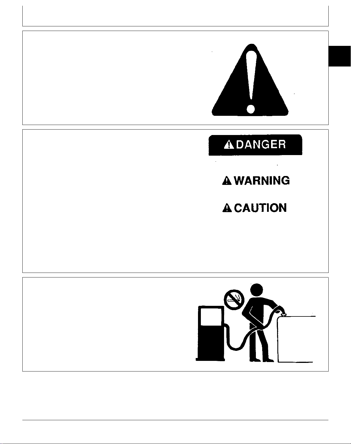
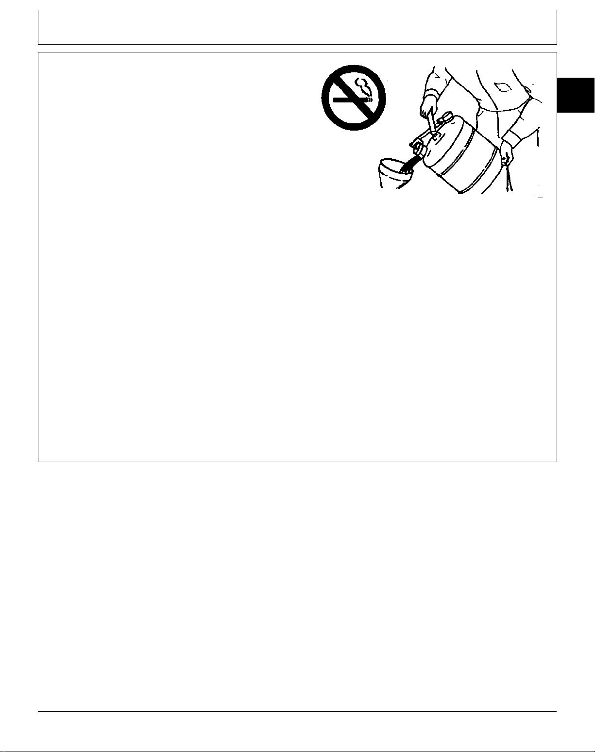
HANDLE FUEL SAFELY—AVOID FIRES
Handle fuel with care: it is highly flammable. Do not
refuel the machine while smoking or when near open
flame or sparks.
Always stop engine before refueling machine. Fill fuel
tank outdoors.
Prevent fires by keeping machine clean of accumulated
trash, grease, and debris. Always clean up spilled fuel.
053,FIRE1 -19-23APR87
TM1351 (18APR90) 10-05-1 130 - 185 LAWN TRACTORS
150196
PN=5
TS202 -UN-23AUG88
Page 12
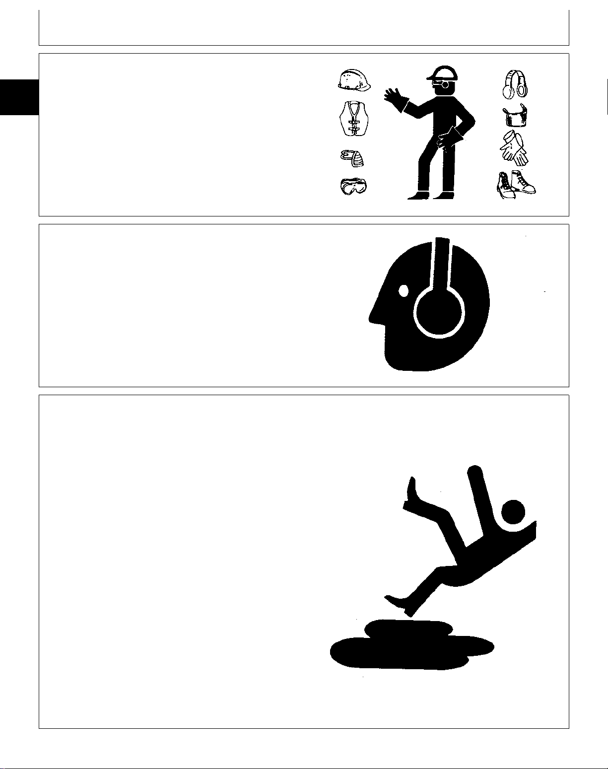
WEAR PROTECTIVE CLOTHING
10
Wear close fitting clothing and safety equipment
05
appropriate to the job.
2
PROTECT AGAINST NOISE
Prolonged exposure to loud noise can cause impairment
or loss of hearing.
Wear a suitable hearing protective device such as
earmuffs or earplugs to protect against objectionable or
uncomfortable loud noises.
Safety
TS206 -UN-23AUG88
O53,WEAR2 -19-23APR87
PRACTICE SAFE MAINTENANCE
Understand service procedure before doing work. Keep
area clean and dry.
Never lubricate or service machine while it is moving.
Keep hands, feet, and clothing from power-driven parts.
Disengage all power and operate controls to relieve
pressure. Lower equipment to the ground. Stop the
engine. Remove the key. Allow machine to cool.
Securely support any machine elements that must be
raised for service work.
Keep all parts in good condition and properly installed.
Fix damage immediately. Replace worn or broken parts.
Remove any buildup of grease, oil, or debris.
Disconnect battery ground cable (-) before making
adjustments on electrical systems or welding on
machine.
TS207 -UN-23AUG88
O53,NOISE -19-23APR87
O53,SERV -19-21DEC87
TM1351 (18APR90) 10-05-2 130 - 185 LAWN TRACTORS
150196
PN=6
TS218 -UN-23AUG88
Page 13
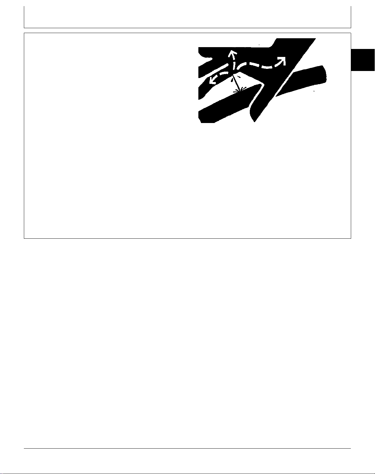
AVOID HIGH-PRESSURE FLUIDS
Safety
Escaping fluid under pressure can penetrate the skin
causing serious injury.
Avoid the hazard by relieving pressure before
disconnecting hydraulic or other lines. Tighten all
connections before applying pressure.
Search for leaks with a piece of cardboard. Protect
hands and body from high pressure fluids.
If an accident occurs, see a doctor immediately. Any
fluid injected into the skin must be surgically removed
within a few hours or gangrene may result. Doctors
unfamiliar with this type of injury may call the Deere &
Company Medical Department in Moline, Illinois, or other
knowledgeable medical source.
10
05
3
X9811 -UN-23AUG88
O53,FLUID -19-01DEC88
TM1351 (18APR90) 10-05-3 130 - 185 LAWN TRACTORS
150196
PN=7
Page 14

10
05
4
Safety
TM1351 (18APR90) 10-05-4 130 - 185 LAWN TRACTORS
150196
PN=8
Page 15

REPAIR SPECIFICATIONS
Group 10
General Specifications
SECTION 20—Engine
Item Specification
PTO Mounting Cap Screw Torque . . . . . . . . . . . . . . . . . . . . . . . . . . . . . . . . . . . . . . . . . 56 N·m (45 lb-ft)
SECTION 40—Electric PTO Clutch
Item Specification
PTO Clutch Clearance . . . . . . . . . . . . . . . . . . . . . . . . . . . . . . . . . . . . . . . . . . . . . . . 0.41 mm (0.016 in.)
SECTION 50—Power Train
Item Specification
Powered Wheels
Wheel Hub-to-Axle Housing Clearance . . . . . . . . . . . . . . . . . . . . . . . . . 0.25—1.02 mm (0.010—0.040 in.)
Traction Drive Clutch
Belt Clearance . . . . . . . . . . . . . . . . . . . . . . . . . . . . . . . . . . . . . . . . . . . . . . . . . . . . 94 mm (3.70 in.)
Belt Guide Clearance . . . . . . . . . . . . . . . . . . . . . . . . . . . . . . . . . . . . . . . . . . . . . . . . . 5 mm (0.20 in.)
5-Speed Transaxle
Needle Bearings
Output Pinion and Input Shaft Depth . . . . . . . . . . . . . . . . . . . . . . . . . . 3.43—3.81 mm (0.135—0.150 in.)
Transaxle Cover Cap Screw Torque . . . . . . . . . . . . . . . . . . . . . . . . . . . . . . . . . . . . . 12 N·m (100 lb-in.)
Hydrostatic Transmission
Eaton
Dump Valve Shaft Torque . . . . . . . . . . . . . . . . . . . . . . . . . . . . . . . . . . . . . . . . . . . . 3 N·m (30 lb-in.)
Body-to-Cover Cap Screw Torque . . . . . . . . . . . . . . . . . . . . . . . . . . . . . . . . . . . . . . 20 N·m (180 lb-in.)
Oil Reservoir Torque . . . . . . . . . . . . . . . . . . . . . . . . . . . . . . . . . . . . . . . . . . . . . . . 14 N·m (124 lb-in.)
Control Arm Clearance . . . . . . . . . . . . . . . . . . . . . . . . . . . . . . . . . . . 0.70—2.50 mm (0.028—0.098 in.)
Control Lever Spring Length . . . . . . . . . . . . . . . . . . . . . . . . . . . . . . . . . . . . . . . . . . 42 mm (1.700 in.)
Sundstrand
Center Section-to-Transmission Cap Screw Torque . . . . . . . . . . . . . . . . . . . . . . . . . . 17 N·m (150 lb-in.)
Drain Plug Torque . . . . . . . . . . . . . . . . . . . . . . . . . . . . . . . . . . . . . . . . . . . . . . . . 15 N·m (130 lb-in.)
Transmission Oil Capacity . . . . . . . . . . . . . . . . . . . . . . . . . . . . . . . . . . . . . . . . . . . 850 cc (28.7 fl oz)
Hydrostatic Differential
Peerless
Ring Gear Cap Screw Torque . . . . . . . . . . . . . . . . . . . . . . . . . . . . . . . . . . . . . . . . . 10 N·m (88 lb-in.)
Differential Cover Cap Screw Torque . . . . . . . . . . . . . . . . . . . . . . . . . . . . . . . . . . . . . 11 N·m (97 lb-in.)
Differential Carrier-to-Case Thrust Surface Maximum Wear . . . . . . . . . . . . . . . . . . . . 1.02 mm (0.040 in.)
10
10
1
M21,1010S,A1 -19-13MAY88
TM1351 (18APR90) 10-10-1 130 - 185 LAWN TRACTORS
150196
PN=9
Page 16

General Specifications/Repair Specifications
SECTION 50—Power Train (cont’d)
10
10
Item Specification
2
Hydrostatic Differential (cont’d)
Kanzaki
Idle Gear I.D. . . . . . . . . . . . . . . . . . . . . . . . . . . . . . . . . . . . . . . . 21.01—21.03 mm (0.827—0.828 in.)
Idler Shaft O.D. . . . . . . . . . . . . . . . . . . . . . . . . . . . . . . . . . . . . . . 16.99—17.00 mm (0.668—0.669 in.)
Cam Lever Shaft O.D. . . . . . . . . . . . . . . . . . . . . . . . . . . . . . . . . . . 19.97—20.03 mm (0.786—0.788 in.)
Cam Lever Shaft Bore I.D. (Cover) . . . . . . . . . . . . . . . . . . . . . . . . . 20.10—20.20 mm (0.791—0.795 in.)
Cam Lever Shaft Bore I.D. (Housing) . . . . . . . . . . . . . . . . . . . . . . . . 20.05—20.08 mm (0.789—0.790 in.)
Actuator Thickness (Includes Ball) . . . . . . . . . . . . . . . . . . . . . . . . . . . . 9.10—9.30 mm (0.358—0.366 in.)
Disc Thickness . . . . . . . . . . . . . . . . . . . . . . . . . . . . . . . . . . . . . . . . 1.90—2.10 mm (0.075—0.083 in.)
Plate Thickness . . . . . . . . . . . . . . . . . . . . . . . . . . . . . . . . . . . . . . . . 2.40—2.60 mm (0.094—0.102 in.)
Axle Housing (Needle Bearing) O.D. . . . . . . . . . . . . . . . . . . . . . . . . 24.98—25.00 mm (0.983—0.984 in.)
Counter Gear I.D. . . . . . . . . . . . . . . . . . . . . . . . . . . . . . . . . . . . . . 20.01—20.03 mm (0.788—0.789 in.)
Pinion Drive O.D. . . . . . . . . . . . . . . . . . . . . . . . . . . . . . . . . . . . . . 20.00—20.02 mm (0.787—0.788 in.)
Pinion Shaft O.D. . . . . . . . . . . . . . . . . . . . . . . . . . . . . . . . . . . . . . 13.97—13.98 mm (0.549—0.550 in.)
Pinion Gear I.D. . . . . . . . . . . . . . . . . . . . . . . . . . . . . . . . . . . . . . . 14.03—14.05 mm (0.552—0.553 in.)
Differential Case (Axle End) I.D. . . . . . . . . . . . . . . . . . . . . . . . . . . . 20.08—20.10 mm (0.790—0.791 in.)
Ring Gear Cap Screw Torque . . . . . . . . . . . . . . . . . . . . . . . . . . . . . . . . . . . . . . . . 26 N·m (230 lb-in.)
Bearing Retainer Tapping Bolts
New Case Torque . . . . . . . . . . . . . . . . . . . . . . . . . . . . . . . . . . . . . . . . . . . . . . . . . 29 N·m (22 lb-ft)
Used Case Torque . . . . . . . . . . . . . . . . . . . . . . . . . . . . . . . . . . . . . . . . . . . . . . . 25 N·m (221 lb-in.)
Axle Tapping Bolts
New Case Torque . . . . . . . . . . . . . . . . . . . . . . . . . . . . . . . . . . . . . . . . . . . . . . . . . 29 N·m (22 lb-ft)
Used Case Torque . . . . . . . . . . . . . . . . . . . . . . . . . . . . . . . . . . . . . . . . . . . . . . . 25 N·m (221 lb-in.)
Ring Gear-to-Pinion Drive Gear Backlash . . . . . . . . . . . . . . . . . . . . . . . 0.15—0.30 mm (0.006—0.012 in.)
Cam Lever Shaft Tapping Bolt
New Case Torque . . . . . . . . . . . . . . . . . . . . . . . . . . . . . . . . . . . . . . . . . . . . . . . . . 29 N·m (22 lb-ft)
Used Case Torque . . . . . . . . . . . . . . . . . . . . . . . . . . . . . . . . . . . . . . . . . . . . . . . 25 N·m (221 lb-in.)
Case Cover Tapping Bolts
New Case Torque . . . . . . . . . . . . . . . . . . . . . . . . . . . . . . . . . . . . . . . . . . . . . . . . . 29 N·m (22 lb-ft)
Used Case Torque . . . . . . . . . . . . . . . . . . . . . . . . . . . . . . . . . . . . . . . . . . . . . . . 25 N·m (221 lb-in.)
Drain Plug Torque . . . . . . . . . . . . . . . . . . . . . . . . . . . . . . . . . . . . . . . . . . . . . . . . 15 N·m (130 lb-in.)
SECTION 60—Steering and Brakes
Item Specification
Brake Disk Gap Clearance . . . . . . . . . . . . . . . . . . . . . . . . . . . . . . . . . . . . . . . . . . . . 0.50 mm (0.020 in.)
SECTION 80—Miscellaneous
Item Specification
Mower Spindle
Maximum Mower Spindle Rolling Torque . . . . . . . . . . . . . . . . . . . . . . . . . . . . . . . . 0.07 N·m (0.60 lb-in.)
Spindle Mounting Bolt Torque . . . . . . . . . . . . . . . . . . . . . . . . . . . . . . . . . . . . . . . . . 25 N·m (221 lb-in.)
Mower Blade Cap Screw Torque . . . . . . . . . . . . . . . . . . . . . . . . . . . . . . . . . . . . . . . . 75 N·m (55 lb-ft)
Mower Drive Sheave Nut Torque . . . . . . . . . . . . . . . . . . . . . . . . . . . . . . . . . . . . . . . 125 N·m (92 lb-ft)
M21,1010S,A2 -19-13MAY88
TM1351 (18APR90) 10-10-2 130 - 185 LAWN TRACTORS
150196
PN=10
Page 17

TRACTOR SPECIFICATIONS
General Specifications/Tractor Specifications
ENGINE
Manufacture . . . . . . . . . . . . . . . . . . . . . . . . . . . . . KAWASAKI
Engine Model Number
130 . . . . . . . . . . . . . . . . . . . . . . . . . . . . . . . . . . . FC290V
160/165 . . . . . . . . . . . . . . . . . . . . . . . . . . . . . . . . FB460V
175 . . . . . . . . . . . . . . . . . . . . . . . . . . . . . . . . . . . FC420V
180/185 . . . . . . . . . . . . . . . . . . . . . . . . . . . . . . . . FC540V
Horsepower
130 . . . . . . . . . . . . . . . . . . . . . . . . . . . . . . . . . . . . . . . . 9
160/165 . . . . . . . . . . . . . . . . . . . . . . . . . . . . . . . . . . . 12.5
175 . . . . . . . . . . . . . . . . . . . . . . . . . . . . . . . . . . . . . . . 14
180/185 . . . . . . . . . . . . . . . . . . . . . . . . . . . . . . . . . . . . 17
Cylinders . . . . . . . . . . . . . . . . . . . . . . . . . . . . . . . . . . . . One
Cycle . . . . . . . . . . . . . . . . . . . . . . . . . . . . . . . . . . . . . . Four
Speeds
Full throttle, no load . . . . . . . . . . . . . . . . . . 3350 ± 100 rpm
Slow idle, no load . . . . . . . . . . . . . . . . . . . . 1400 ± 100 rpm
Spark Plug Type
130 . . . . . . . . . . . . . . . . . . . . . . . . . . . Champion RN11YC
160/165 . . . . . . . . . . . . . . . . . . . . . . . . . . Champion RCJ8
NGK-BMR4A
175 . . . . . . . . . . . . . . . . . . . . . . . . . . . Champion RN11YC
180/185 . . . . . . . . . . . . . . . . . . . . . . . . Champion RN11YC
Spark Plug Gap
130, 175, 180/185 . . . . . . . . . . . . . . . . . . . . 0.70—0.80 mm
(0.028—0.031 in.)
160/165 . . . . . . . . . . . . . . . . . . . . . . . . . . . 0.60—0.70 mm
(0.024—0.028 in.)
ELECTRICAL SYSTEM
Battery, John Deere
(TY6109) . . . . . . . . . . . . . . . . . . . . . . . . . . . . . . . . . . 12 Volt
255 amp cold cranking capacity
capacity at 25 amp
Alternator Charging Capacity
130 . . . . . . . . . . . . . . . . . . . . . . . . . . . . . . . . . . . 13 Amp
160/165 . . . . . . . . . . . . . . . . . . . . . . . . . . . . . . . . 13 Amp
175 . . . . . . . . . . . . . . . . . . . . . . . . . . . . . . . . . . . 13 Amp
180/185 . . . . . . . . . . . . . . . . . . . . . . . . . . . . . . . . 15 Amp
Ignition . . . . . . . . . . . . . . . . . . . . . . . . . . . . . . . . Solid State
CAPACITIES
Fuel Tank . . . . . . . . . . . . . . . . . . . . . . . . . . . . 8.3 L (2.2 gal)
Engine Oil, Without Filter
130 . . . . . . . . . . . . . . . . . . . . . . . . . . . . . . . . 1.1 L (2.3 pt)
160/165 . . . . . . . . . . . . . . . . . . . . . . . . . . . . . . 1.4 L (3 pt)
175 . . . . . . . . . . . . . . . . . . . . . . . . . . . . . . . . 1.3 L (2.7 pt)
180/185 . . . . . . . . . . . . . . . . . . . . . . . . . . . . . 1.6 L (3.4 pt)
Engine Oil, With Filter
160/165 . . . . . . . . . . . . . . . . . . . . . . . . . . . . . 1.6 L (3.4 pt)
175 . . . . . . . . . . . . . . . . . . . . . . . . . . . . . . . . 1.7 L (3.6 pt)
180/185 . . . . . . . . . . . . . . . . . . . . . . . . . . . . . 2.0 L (4.2 pt)
Transaxle
130/160/180 . . . . . . . . . . . . . . . . . . . . . . . . . . 1.1 L (2.3 pt)
Hydrostatic Transmission
165/175/185 . . . . . . . . . . . . . . . . . . . . . . . . . . 0.7 L (1.5 pt)
Differential
165/175/185 . . . . . . . . . . . . . . . . . . . . . . . . . . 0.7 L (1.5 pt)
TRAVEL SPEEDS AT 3300 RPM
First Gear-Transaxle
130/160/180 . . . . . . . . . . . . . . . . . . . . . 2.2 km/h (1.4 mph)
180 w/46 in. Mower . . . . . . . . . . . . . . . . 2.4 km/h (1.5 mph)
Second Gear
130/160/180 . . . . . . . . . . . . . . . . . . . . . 3.5 km/h (2.2 mph)
180 w/46 in. Mower . . . . . . . . . . . . . . . . 3.8 km/h (2.4 mph)
Third Gear
130/160/180 . . . . . . . . . . . . . . . . . . . . . 5.3 km/h (3.3 mph)
180 w/46 in. Mower . . . . . . . . . . . . . . . . 5.6 km/h (3.5 mph)
Fourth Gear
130/160/180 . . . . . . . . . . . . . . . . . . . . . 6.7 km/h (4.2 mph)
180 w/46 in. Mower . . . . . . . . . . . . . . . . 7.2 km/h (4.5 mph)
Fifth Gear
130/160/180 . . . . . . . . . . . . . . . . . . . . . 7.8 km/h (4.9 mph)
180 w/46 in. Mower . . . . . . . . . . . . . . . . 8.5 km/h (5.3 mph)
Hydrostatic Transmission
Forward . . . . . . . . . . . . . . . . . . . . . . . . 0-8 km/h (0-5 mph)
Reverse . . . . . . . . . . . . . . . . . . . . . . . 0-4 km/h (0-2.5 mph)
APPROXIMATE WEIGHT
130 . . . . . . . . . . . . . . . . . . . . . . . . . . . . . . . . 184 kg (405 lb)
160 . . . . . . . . . . . . . . . . . . . . . . . . . . . . . . . . 202 kg (445 lb)
165 and 175 . . . . . . . . . . . . . . . . . . . . . . . . . . 213 kg (470 lb)
180 with 30 in. Mower . . . . . . . . . . . . . . . . . . . 220 kg (485 lb)
180 with 46 in. Mower . . . . . . . . . . . . . . . . . . . 236 kg (520 lb)
180 with 38 in. Mower . . . . . . . . . . . . . . . . . . . 231 kg (510 lb)
10
10
3
M21,1010S,A3 -19-16MAY88
TM1351 (18APR90) 10-10-3 130 - 185 LAWN TRACTORS
150196
PN=11
Page 18

General Specifications/Mower Specifications
MOWER SPECIFICATIONS
10
Item 30-Inch 38-Inch 46-Inch
10
Type Rotary Rotary Rotary
4
Cutting Blades One Two Three
Blade Length 762 mm (30 in.) 496 mm (19.50 in.) 407 mm (16 in.)
Cutting Width 762 mm (30 in.) 965 mm (38 in.) 1170 mm (46 in.)
Cutting Height 25.40—102 mm 25.40—102 mm 38.10 . . . . . . . 102 mm
(1.00—4.00 in.) (1.00—4.00 in.) (1.50—4.00 in.)
Specifications and design subject to change without notice.
M21,1010S,A4 -19-16MAY88
TM1351 (18APR90) 10-10-4 130 - 185 LAWN TRACTORS
150196
PN=12
Page 19
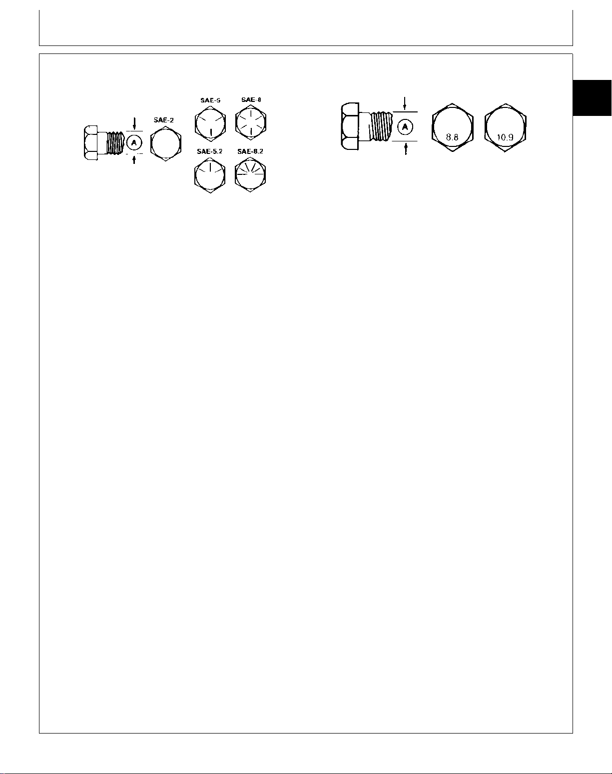
CAP SCREW TORQUE VALUES
Inch Cap Screw Head Markings
TS300 -UN-09AUG89
Metric Cap Screw Head Markings
TS299 -UN-09AUG89
Group 15
Cap Screw Torque
10
15
1
INCH CAP SCREW TORQUE VALUES
Cap Screw Grade
Bolt SAE 2 SAE 5 SAE 8
Diameter Wrench
(A) Size N·m lb-ft N·m lb-ft N·m lb-ft
1/4“ 7/16“ 7 (5) 11 (8) 16 (12)
5/16“ 1/2“ 14 (10) 23 (17) 33 (24)
3/8“ 9/16“ 24 (18) 41 (30) 54 (40)
7/16“ 5/8“ 41 (30) 68 (50) 95 (70)
1/2“ 3/4“ 61 (45) 102 (75) 142 (105)
9/16“ 13/16“ 88 (65) 142 (105) 203 (150)
5/8“ 15/16“ 122 (90) 197 (145) 278 (205)
3/4“ 1-1/8“ 217 (160) 353 (260) 495 (365)
7/8“ 1-5/16“ 224 (165) 563 (415) 800 (590)
1“ 1-1/2“ 332 (245) 848 (625) 1193 (880)
1-1/4“ 1-7/8“ 665 (490) 1492 (1100) 2393 (1765)
CAUTION: Use only metric tools on metric
N
hardware. Other tools may not fit properly.
They may slip and cause injury.
DO NOT use these values if a different torque value
or tightening procedure is listed for a specific
application. Torque values listed are for general use
only. Check tightness of cap screws periodically.
Shear bolts are designed to fail under predetermined
loads. Always replace shear bolts with identical grade.
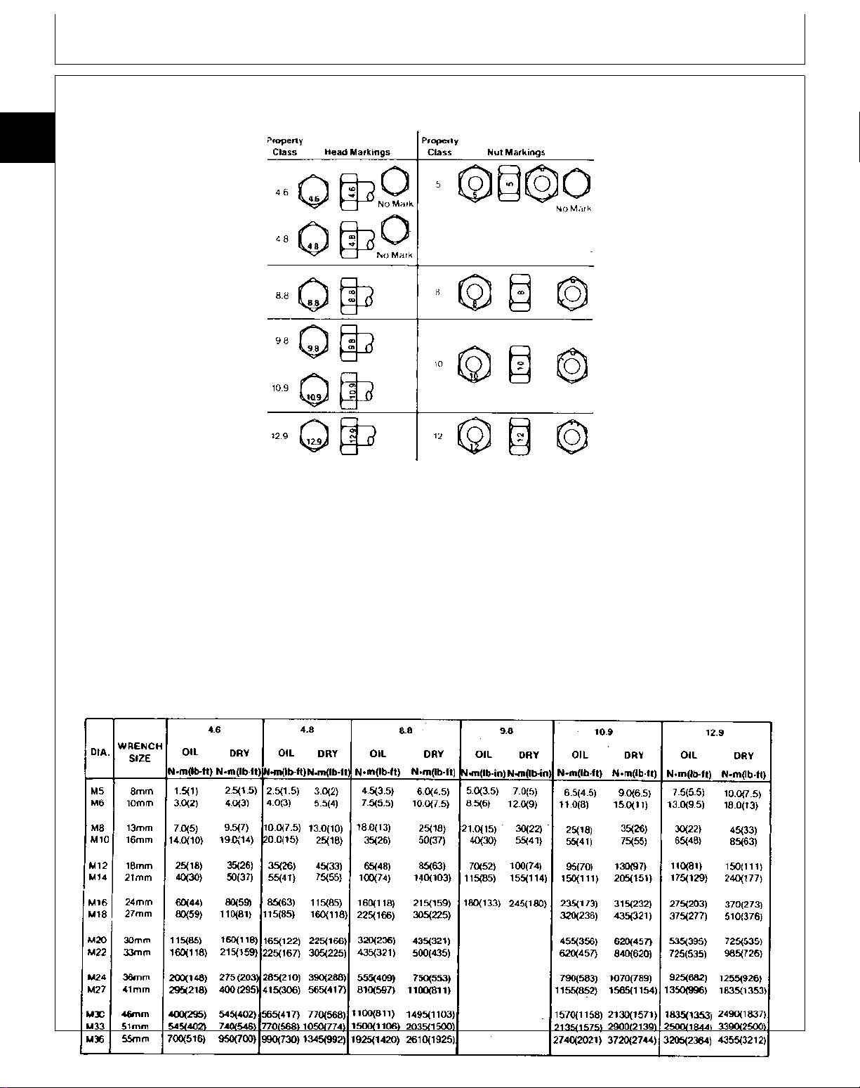
METRIC CAP SCREW TORQUE VALUES
Markings on Cap Screw Heads
Bolt 8.8 10.9
Diameter Wrench
(A) Size N·m lb-ft N·m lb-ft
5 mm 8 mm 6 (4.5) 9 (6.5)
6 mm 10 mm 10 (7.5) 15 (11)
8 mm 13 mm 25 (18) 35 (26)
10 mm 16 mm 50 (37) 75 (55)
12 mm 18 mm 85 (63) 130 (97)
16 mm 24 mm 215 (159) 315 (232)
20 mm 30 mm 435 (312) 620 (457)
24 mm 36 mm 750 (553) 1070 (789)
30 mm 46 mm 1495 (1103) 2130 (1571)
Fasteners should be replaced with the same or
higher grade. If higher grade fasteners are used,
these should only be tightened to the strength of the
original.
Make sure fastener threads are clean and you
properly start thread engagement. This will prevent
them from failing when tightening.
Tighten plastic insert or crimped steel-type lock nuts
to approximately 50 percent of amount shown in
chart. Tighten toothed or serrated-type lock nuts to
full torque value.
O53,TORQ3 -19-07OCT88
TM1351 (18APR90) 10-15-1 130 - 185 LAWN TRACTORS
150196
PN=13
Page 20
METRIC SERIES TORQUE CHART
10
15
2
Cap Screw Torque/Metric Series torque Chart
CAUTION: Use only metric tools on metric
N
hardware. Other tools may not fit properly.
They may slip and cause injury.
Check tightness of cap screws periodically. Torque
values listed are for general use only. Do not use
these values if a different torque value or tightening
procedure is listed for a specific application.
Shear bolts are designed to fail under predetermined
loads. Always replace shear bolts with identical grade.
TS234 -19-19DEC88
Fasteners should be replaced with the same or
higher grade. If higher grade fasteners are used,
these should only be tightened to the strength of the
original.
Make sure fastener threads are clean and you
properly start thread engagement. This will prevent
them from failing when tightening.
Tighten cap screws having lock nuts to approximately
50 percent of amount shown in chart.
053,TORQ4 -19-22JAN88
TM1351 (18APR90) 10-15-2 130 - 185 LAWN TRACTORS
150196
TS235 -19-08MAY95
PN=14
Page 21

TUNE-UP SPECIFICATIONS
Group 20
Tune-Up
Spark Plug Gap
130, 175, 180/185 . . . . . . . . . . . . . . . . . . . . . . . . . . . . . . . . . . . . . . . . . 0.70—0.80 mm (0.028—0.031 in.)
160/165 . . . . . . . . . . . . . . . . . . . . . . . . . . . . . . . . . . . . . . . . . . . . . . . 0.60—0.70 mm (0.024—0.028 in.)
Spark Plug Torque . . . . . . . . . . . . . . . . . . . . . . . . . . . . . . . . . . . . . . . . . . . . . . . . . . 15 N·m (133 lb-in.)
Idle Speed . . . . . . . . . . . . . . . . . . . . . . . . . . . . . . . . . . . . . . . . . . . . . . . . . . . . . . . . . . . . . . 1400 rpm
High Speed . . . . . . . . . . . . . . . . . . . . . . . . . . . . . . . . . . . . . . . . . . . . . . . . . . . . . . . . . . . . . 3350 rpm
M21,1020S,A2 -19-16MAY88
TUNE-UP SPECIFICATIONS
Perform tune-up adjustments in the following order to
improve the efficiency and operation of the tractor.
Tune-Up Adjustment Section Group
1. Clean engine and cooling system.
2. Clean air cleaner.
3. Check or replace fuel filter.
4. Check battery electrolyte level.
5. Check spark. 220 10
6. Check spark plug. 220 10
7. Check compression. 220 10
8. Adjust carburetor and engine speeds. 220 10
9. Check crankcase breather. CTM-5
10. Check crankcase vacuum. 220 10
11. Check and adjust governor. 220 10
12. Check and adjust brakes. 60 15
13. Check and adjust hydrostatic control lever
linkage. 250 10
14. Check hydrostatic control lever friction
adjustment. 250 10
15. Adjust steering axle. 60 10
16. Check tire pressure. 05
10
20
1
M21,1020S,A1 -19-18APR88
TM1351 (18APR90) 10-20-1 130 - 185 LAWN TRACTORS
150196
PN=15
Page 22

10
20
2
Tune-Up/Adjustments
TM1351 (18APR90) 10-20-2 130 - 185 LAWN TRACTORS
150196
PN=16
Page 23
FUEL
Group 25
Fuel and Lubrication
CAUTION: Handle fuel carefully. Always stop
N
engine before refueling. Fill fuel tank outdoors.
If engine is hot, let engine cool several
minutes before you add fuel. Do not smoke
while you fill the fuel tank or service the fuel
system. Fill fuel tank only to bottom of filler
neck.
IMPORTANT: DO NOT mix oil with gasoline.
Unleaded fuel is recommended. Regular leaded gasoline
with an anti-knock index of 87 or higher may be used.
Avoid switch from unleaded to regular gasoline to
prevent engine damage.
Use of gasohol is acceptable as long as the ethyl
alcohol blend does not exceed 10 per cent. Unleaded
gasohol is preferred over leaded gasohol.
Fuel tank capacity is 2-1/2 gal (9.5 L).
Lift seat. Fill fuel tank at end of each day’s operation.
This helps to keep condensation out of fuel tank.
10
25
1
TS185 -UN-23AUG88
M21,FLS,A -19-03APR87
TM1351 (18APR90) 10-25-1 130 - 185 LAWN TRACTORS
150196
PN=17
Page 24
Fuel and Lubrication/Peerless Differential Oil
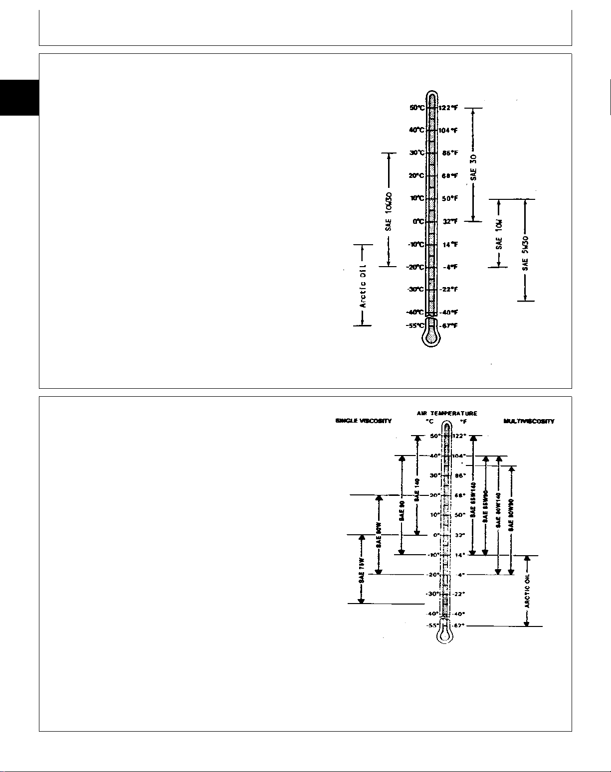
GASOLINE ENGINE OIL
10
Use oil viscosity based on the expected air temperature
25
range during the period between oil changes.
2
John Deere PLUS-4® engine oil is recommended.
Other oils may be used if they meet API Service
Classification SF or SE.
Oils meeting Military Specification MIL-L-46167A may be
used as arctic oils.
PEERLESS DIFFERENTIAL OIL—ALL 165,
175 AND 185 (S.N. —475000)
Use oil viscosity as shown on the temperature chart for
the expected air temperature range during the drain
interval.
SAE 90 oil is recommended in the differential. Other oils
shown in the chart can also be used. DO NOT mix oils
of different viscosities.
IMPORTANT: DO NOT put SAE 90 oil in the
hydrostatic transmission.
TS239 -19-09NOV88
O53,GAS -19-05FEB88
X9322 -19-30SEP88
M21,1025S,A1 -19-13MAY88
TM1351 (18APR90) 10-25-2 130 - 185 LAWN TRACTORS
150196
PN=18
Page 25

Fuel and Lubrication/Substrand Hydrostatic Transmission Oil
KANZAKI DIFFERENTIAL OIL—185 (S.N.
475001— )
SAE 10W30 engine oil with an API classification of SE,
CC or CD is recommended in the differential. DO NOT
mix oils of different viscosities.
IMPORTANT: DO NOT put SAE 90 oil in the
hydrostatic transmission or differential.
EATON HYDROSTATIC TRANSMISSION
OIL—ALL 165, 175 AND 185 (S.N.
—475000)
IMPORTANT: DO NOT use type F automatic
transmission fluid or any other type oil
other than specified. Oil must be from
a sealed plastic or all metal can to
avoid any moisture.
10
25
3
M21,1025S,A2 -19-13MAY88
SAE 30 engine oil with an API classification of SE, CC
or CD is recommended in the transmission. SAE 20 or
40 engine oil can also be used depending on
temperature range during the service interval.
SUNDSTRAND HYDROSTATIC
TRANSMISSION OIL—185 (S.N. 475001— )
SAE 10W 30 engine oil with an API classification of SE,
CC or CD is recommended in the transmission.
M21,1025S,A3 -19-13MAY88
M21,1025S,A4 -19-13MAY88
TM1351 (18APR90) 10-25-3 130 - 185 LAWN TRACTORS
150196
PN=19
Page 26
Fuel and Lubrication/General Purpose grease
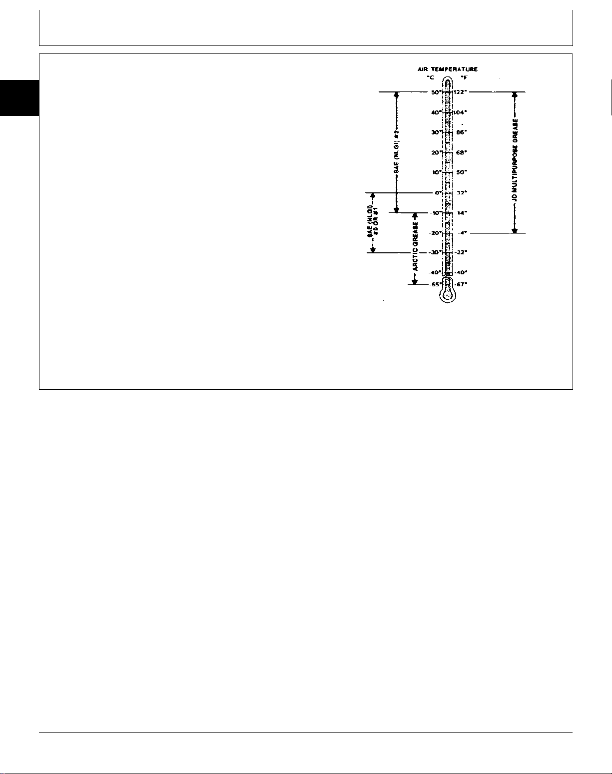
GENERAL PURPOSE GREASE
10
Use grease as shown on the temperature chart for the
25
expected air temperature range during the service
4
interval.
John Deere Multipurpose Grease is recommended. If
other greases are used, use:
—SAE Multipurpose Grease.
—Multipurpose Grease containing 3 to 5 percent
molybdenum disulfide.
At temperatures below -22˚F (-30˚C), use arctic greases
such as those meeting Military Specification
MIL-G-10924C.
X9326 -19-30SEP88
M21,FLJ,05 -19-12MAY83
TM1351 (18APR90) 10-25-4 130 - 185 LAWN TRACTORS
150196
PN=20
Page 27

PRODUCT IDENTIFICATION NUMBER
ENGINE SERIAL NUMBER
Group 30
Serial Numbers
10
30
1
M38557 -UN-29AUG88
M21,1030S,1 -19-13FEB86
M21,1030S,2 -19-13FEB86
M38600 -UN-29AUG88
TM1351 (18APR90) 10-30-1 130 - 185 LAWN TRACTORS
150196
PN=21
Page 28

10
30
2
Serial Numbers/Engine Serial Number
TM1351 (18APR90) 10-30-2 130 - 185 LAWN TRACTORS
150196
PN=22
Page 29

Page
Group 05—Remove and Install
Kawasaki Engine Repair—Use CTM-5 . . . 20-05-1
Other Materials . . . . . . . . . . . . . . . . . . 20-05-1
Remove and Install Engine
130 . . . . . . . . . . . . . . . . . . . . . . . . 20-05-1
160 and 165 . . . . . . . . . . . . . . . . . . 20-05-3
175, 180 and 185 . . . . . . . . . . . . . . . 20-05-6
Group 10—Muffler
Replace Muffler
130 . . . . . . . . . . . . . . . . . . . . . . . . 20-10-1
160 and 165 . . . . . . . . . . . . . . . . . . 20-10-2
175, 180 and 185 . . . . . . . . . . . . . . . 20-10-3
Section 20
Engine
Contents
20
TM1351 (18APR90) 20-1 130 - 185 LAWN TRACTORS
150196
PN=247
Page 30

20
Contents
TM1351 (18APR90) 20-2 130 - 185 LAWN TRACTORS
150196
PN=248
Page 31

Remove and Install
KAWASAKI ENGINE REPAIR—USE CTM-5
For complete repair information the component technical
manual (CTM) is also required.
Use the component manual in conjunction with this
machine manual.
OTHER MATERIAL
Number Name Use
Group 05
20
05
1
TS225 -UN-17JAN89
M21,2005S,A1 -19-18APR88
PT569 NEVER-SEEZ
Lubricant
NEVER-SEEZ is a trademark of the Never-Seez Corp.
REMOVE AND INSTALL ENGINE—130
1. Remove hood, muffler and pedestal shroud.
CAUTION: Gasoline is dangerous. Avoid fires
N
due to smoking or careless maintenance
practices.
2. Close fuel shut-off valve. Disconnect fuel line.
®
Lubricate crankshaft
M21,2005S,X -19-20JAN86
M50205 -UN-22DEC89
M21,2005S,A2 -19-18APR88
3. Loosen cap screw and disconnect throttle cable.
M21,2005S,A3 -19-18APR88
TM1351 (18APR90) 20-05-1 130 - 185 LAWN TRACTORS
150196
PN=23
M50206 -UN-22DEC89
Page 32

Remove and Install/Remove and Install Engine
4. Disconnect two wires from ground terminal on
right-hand side of engine.
20
05
2
5. Disconnect wire from starter.
M50207 -UN-22DEC89
M21,2005S,A4 -19-18APR88
6. Disconnect ignition wire (A) and remove wire from
grommet (B).
7. Remove electric PTO clutch. (See Section 40, Group
05.)
8. Depress clutch pedal and remove belt from idler
wheel and drive sheave.
9. Remove drive sheave (A) and key (B).
M50208 -UN-22DEC89
M21,2005S,A5 -19-18APR88
M50209 -UN-22DEC89
M21,2005S,A6 -19-18APR88
M21,2005S,A7 -19-18APR88
TM1351 (18APR90) 20-05-2 130 - 185 LAWN TRACTORS
150196
PN=24
M50210 -UN-22DEC89
Page 33

Remove and Install/Remove and Install Engine
10. Remove four engine mounting cap screws and belt
guide (A).
11. Rotate engine to clear oil drain from hole in frame
and remove engine.
12. When installing engine, apply NEVER-SEEZE
lubricant to crankshaft before installing drive sheave.
13. Tighten PTO clutch mounting cap screw to 56 N·m
(45 lb-ft).
20
05
3
M50211 -UN-22DEC89
M21,2005S,A8 -19-18APR88
14. Adjust throttle cable, choke, governor, fast idle and
slow idle. (See Section 220.)
REMOVE AND INSTALL ENGINE—160 AND
165
1. Remove hood, muffler and pedestal shroud.
CAUTION: Gasoline is dangerous. Avoid fires
N
due to smoking or careless maintenance
practices.
2. Close fuel shut-off valve. Disconnect fuel line.
3. Disconnect throttle cable (A).
M50212 -UN-29JAN90
M21,2005S,A9 -19-13MAY88
M50220 -UN-22DEC89
M21,2005S,A10 -19-18APR88
TM1351 (18APR90) 20-05-3 130 - 185 LAWN TRACTORS
150196
PN=25
Page 34

Remove and Install/Remove and Install Engine
4. Disconnect two wires from ground terminal on
right-hand side of engine.
20
05
4
5. Disconnect wires (A and B). Remove wires from
behind oil fill tube (C).
M50221 -UN-22DEC89
M21,2005S,A11 -19-18APR88
6. Disconnect ignition wire (A) and remove wire from
grommet (B).
M50222 -UN-22DEC89
M21,2005S,A12 -19-18APR88
M50223 -UN-22DEC89
M21,2005S,A13 -19-18APR88
TM1351 (18APR90) 20-05-4 130 - 185 LAWN TRACTORS
150196
PN=26
Page 35

Remove and Install/Remove and Install Engine
7. Remove electric PTO clutch. (See Section 40, Group
05.)
8. Relieve tension in traction belt for hydrostatic tractors.
For gear driven tractors, depress clutch pedal. Remove
belt from idler wheel and drive sheave.
9. Remove drive sheave (A) and key (B).
Model 160 Shown
10. Remove four engine mounting cap screws. On gear
driven tractors, remove belt guard (A).
20
05
5
M50224 -UN-22DEC89
M21,2005S,A14 -19-18APR88
M21,2005S,A15 -19-18APR88
TM1351 (18APR90) 20-05-5 130 - 185 LAWN TRACTORS
150196
PN=27
M50194 -UN-22DEC89M50225 -UN-22DEC89
Page 36

Remove and Install/Remove and Install Engine
11. Rotate engine to clear oil drain from hole in frame
and remove engine.
12. When installing engine, apply NEVER-SEEZ lubricant
to crankshaft before installing drive sheave.
13. Tighten PTO clutch mounting cap screw to 56 N·m
(45 lb-ft).
20
05
6
14. Adjust throttle cable, choke, governor, fast idle and
slow idle. (See Section 220.)
REMOVE AND INSTALL ENGINE—175, 180
AND 185
1. Remove hood, muffler and pedestal shroud.
CAUTION: Gasoline is dangerous. Avoid fires
N
due to smoking or careless maintenance
practices.
M50226 -UN-22DEC89
M21,2005S,A16 -19-13MAY88
2. Close fuel shut-off valve. Disconnect fuel line.
3. Loosen cap screw and disconnect throttle cable.
4. Disconnect two wires from ground terminal on
right-hand side of engine.
M50187 -UN-22DEC89
M21,2005S,A17 -19-18APR88
M50188 -UN-22DEC89
M21,2005S,A18 -19-18APR88
M21,2005S,A19 -19-18APR88
TM1351 (18APR90) 20-05-6 130 - 185 LAWN TRACTORS
150196
PN=28
M50189 -UN-22DEC89
Page 37

Remove and Install/Remove and Install Engine
5. Disconnect wires (A, B and C) from starter solenoid.
6. Disconnect ignition wire (A) and remove wire from
grommet (B).
20
05
7
M50190 -UN-22DEC89
M21,2005S,A20 -19-18APR88
7. Remove electric PTO clutch. (See Section 40, Group
05.)
8. Relieve tension in traction belt for hydrostatic tractors.
For gear driven tractors, depress clutch pedal. Remove
belt from idler wheel and drive sheave.
9. Remove drive sheave (A) and key (B).
M50191 -UN-22DEC89
M21,2005S,A21 -19-18APR88
M50192 -UN-22DEC89M50193 -UN-22DEC89
Model 185 Shown
M21,2005S,A22 -19-18APR88
TM1351 (18APR90) 20-05-7 130 - 185 LAWN TRACTORS
150196
PN=29
Page 38

Remove and Install/Remove and Install Engine
10. Remove four engine mounting cap screws. On gear
driven units, remove belt guard (A).
20
05
8
M50194 -UN-22DEC89M50225 -UN-22DEC89
11. Rotate engine to clear oil drain from hole in frame
and remove engine.
12. When installing engine, apply NEVER-SEEZ lubricant
to crankshaft before installing drive sheave.
13. Tighten PTO clutch mounting cap screw to 56 N·m
(45 lb-ft).
14. Adjust throttle cable, choke, governor, fast idle and
slow idle. (See Section 220.)
M21,2005S,A23 -19-18APR88
M50195 -UN-22DEC89
M21,2005S,A24 -19-18APR88
TM1351 (18APR90) 20-05-8 130 - 185 LAWN TRACTORS
150196
PN=30
Page 39

REPLACE MUFFLER—MODEL 130
1. Remove hood.
2. Remove four cap screws and remove air duct.
3. Disconnect spark plug wire.
4. Remove engine cover (A).
Group 10
Muffler
20
10
1
M50214 -UN-22DEC89
M21,2020S,F -19-21DEC85
5. Remove two nuts and washers. Remove muffler.
6. Put muffler and gasket into position.
7. Install and tighten two washers and nuts.
8. Install cover (A).
9. Connect spark plug wire.
10. Install air duct.
11. Install hood.
M50215 -UN-22DEC89
M21,2020S,G -19-21DEC85
M50216 -UN-22DEC89
M21,2020S,H -19-21DEC85
TM1351 (18APR90) 20-10-1 130 - 185 LAWN TRACTORS
150196
PN=31
Page 40

Muffler/Replace Muffler
REPLACE MUFFLER—MODELS 160 AND 165
1. Remove hood.
2. Disconnect spark plug wire and remove rubber
grommet to remove spark plug wire from air duct.
20
10
2
3. Remove four cap screws and two cap screws and
nuts from air duct.
4. First, remove right side of air duct (A), then left side
(B).
M50217 -UN-22DEC89
M21,2020S,C -19-21DEC85
5. Remove four cap screws and two spacers and
remove muffler.
6. Position muffler and gasket.
7. Install and tighten two spacers and four cap screws.
8. Install left side of air duct, then right side.
9. Put spark plug wire through hole in air duct and
connect to plug. Install rubber grommet.
10. Install hood.
M50218 -UN-22DEC89
M21,2020S,D -19-21DEC85
M50219 -UN-22DEC89
M21,2020S,E -19-21DEC85
TM1351 (18APR90) 20-10-2 130 - 185 LAWN TRACTORS
150196
PN=32
Page 41

Muffler/Replace Muffler
REPLACE MUFFLER—MODELS 175, 180,
AND 185
1. Remove hood.
2. Remove four cap screws and remove air duct.
3. Remove two nuts, washers and two cap screws (A).
4. Pull out on muffler guard and remove muffler.
5. Position muffler and gasket by pulling out on muffler
shield.
6. Install and tighten two cap screws (A), two nuts and
washers.
20
10
3
M50198 -UN-22DEC89
M21,2020S,A -19-19DEC86
7. Install air duct.
8. Install hood.
M50197 -UN-22DEC89
M21,2020S,B -19-13DEC85
TM1351 (18APR90) 20-10-3 130 - 185 LAWN TRACTORS
150196
PN=33
Page 42

20
10
4
Muffler/Replace Muffler
TM1351 (18APR90) 20-10-4 130 - 185 LAWN TRACTORS
150196
PN=34
Page 43

Group 05—Fuel Pump and Fuel Tank
Air Cleaner, Breather and Carburetor
Repair—Use CTM-5 . . . . . . . . . . . . . 30-05-1
Fuel Pump
Remove . . . . . . . . . . . . . . . . . . . . . 30-05-1
Service . . . . . . . . . . . . . . . . . . . . . . 30-05-1
Fuel Tank
Remove . . . . . . . . . . . . . . . . . . . . . 30-05-3
Inspect . . . . . . . . . . . . . . . . . . . . . . 30-05-4
Disassemble . . . . . . . . . . . . . . . . . . 30-05-4
Assemble . . . . . . . . . . . . . . . . . . . . 30-05-4
Install . . . . . . . . . . . . . . . . . . . . . . . 30-05-5
Section 30
Fuel and Air System
Contents
Page
30
TM1351 (18APR90) 30-1 130 - 185 LAWN TRACTORS
150196
PN=249
Page 44

30
Contents
TM1351 (18APR90) 30-2 130 - 185 LAWN TRACTORS
150196
PN=250
Page 45

AIR CLEANER, BREATHER AND
CARBURETOR REPAIR—USE CTM-5
For complete repair information the component technical
manual (CTM) is also required.
Use the component manual in conjunction with this
machine manual.
REMOVE FUEL PUMP
CAUTION: Gasoline is dangerous. Avoid fires
N
due to smoking or careless maintenance
practices.
Group 05
Fuel Pump and Fuel Tank
TS225 -UN-17JAN89
M21,3005S,A1 -19-18APR88
30
05
1
1. Test fuel pump before removal. (See Section 220.)
2. Disconnect vacuum line and fuel lines (A and B).
3. Remove fuel pump.
SERVICE FUEL PUMP
1. Remove screws and washers.
2. Remove cover, gaskets and diaphram. Make sure
vent in cover is not plugged. Inspect diaphram for
hairline cracks or wear.
3. Remove pump body and gasket (A).
M50185 -UN-22DEC89
M21,3005S,A2 -19-18APR88
M50199 -UN-31AUG88
M21,3005S,A3 -19-13MAY88
M21,3005S,E -19-11DEC85
TM1351 (18APR90) 30-05-1 130 - 185 LAWN TRACTORS
150196
PN=35
M50201 -UN-31AUG88
Page 46

Fuel Pump and Fuel Tank/Fuel Pump
4. Remove valves by pulling rubber grommet. Inspect
valves for hairline cracks or wear.
30
05
5. Remove bottom diaphram and gasket. Inspect
2
diaphram for holes, wrinkles or wear.
6. Inspect all pump mounting surfaces. They must be
free of any nicks or burrs. Replace any worn or
damaged gaskets or diaphragms.
M50202 -UN-31AUG88
M21,3005S,F -19-11DEC85
7. When installing inlet and outlet valve assemblies, use
a punch or small dull shaft to stretch rubber grommet.
Push stretched assembly into pump body.
8. When assembling pump body, be sure flat area on
bottom plate and pump body match.
M50203 -UN-31AUG88
M21,3005S,G -19-11DEC85
M50204 -UN-31AUG88
M21,3005S,A4 -19-18APR88
TM1351 (18APR90) 30-05-2 130 - 185 LAWN TRACTORS
150196
PN=36
Page 47

Fuel Pump and Fuel Tank/Fuel Tank
REMOVE FUEL TANK
1. Remove mower height knob, park brake knob (A) and
transmission selector knob (B).
On hydrostatic tractors, remove tow valve knob (C).
2. Disconnect seat switch.
3. Remove pedestal shroud and platform.
M50172 -UN-22DEC89M50173 -UN-22DEC89
30
05
3
CAUTION: Gasoline is dangerous. Avoid fires
N
due to smoking or careless maintenance
practices.
4. Close shut-off valve. Disconnect fuel line and remove
it from foam pad.
5. Disconnect fuel sensor wiring harness and remove it
from foam pad.
6. Remove fuel tank.
M21,3005S,A5 -19-18APR88
M50178 -UN-22DEC89
M21,3005S,A6 -19-18APR88
M21,3005S,A7 -19-18APR88
TM1351 (18APR90) 30-05-3 130 - 185 LAWN TRACTORS
150196
PN=37
M50179 -UN-22DEC89
Page 48

Fuel Pump and Fuel Tank/Fuel Tank
INSPECT FUEL TANK
1. Replace tank if damaged.
2. Check rubber bushings for leaks or damage. Replace
if necessary. (See Disassemble Fuel Tank in this group.)
3. Make sure overflow tube (A) is not plugged.
30
05
DISASSEMBLE FUEL TANK
4
1. If equipped, pull fuel sensor from tank. Test fuel
sensor. (See Section 240.)
M50180 -UN-22DEC89
M21,3005S,V -19-11DEC85
2. Pull shut-off valve from tank.
ASSEMBLE FUEL TANK
1. Push rubber bushing into tank.
2. Push shut-off valve into housing.
M50181 -UN-22DEC89
M21,3005S,A8 -19-18APR88
M50182 -UN-22DEC89
M21,3005S,X -19-11DEC85
M21,3005S,Y -19-11DEC85
TM1351 (18APR90) 30-05-4 130 - 185 LAWN TRACTORS
150196
PN=38
M50183 -UN-22DEC89
Page 49

Fuel Pump and Fuel Tank/Fuel Tank
3. Push rubber bushing into tank.
4. Push fuel sensor into rubber bushing.
INSTALL FUEL TANK
1. Install tank. Put overflow tube through clip on back of
frame.
2. Put wiring harness under foam pad and connect
harness to fuel sensor.
M50184 -UN-22DEC89
M21,3005S,Z -19-11DEC85
30
05
5
3. Put fuel line under foam pad and connect line to
shut-off valve.
M50179 -UN-22DEC89
M21,3005S,AA -19-11DEC85
M50178 -UN-22DEC89
M21,3005S,AB -19-11DEC85
TM1351 (18APR90) 30-05-5 130 - 185 LAWN TRACTORS
150196
PN=39
Page 50

Fuel Pump and Fuel Tank/Fuel Tank
4. Put platform on frame. Put seat switch connector
through platform. Make sure all levers fit through
platform.
5. Install and tighten two nuts, washers and three cap
screws.
6. Install pedestal shroud.
7. Connect seat switch.
8. Install control knobs.
30
05
6
M50177 -UN-22DEC89
M21,3005S,AC -19-11DEC85
TM1351 (18APR90) 30-05-6 130 - 185 LAWN TRACTORS
150196
PN=40
Page 51

Page
Group 05—Electric PTO Clutch
Stator, Ignition Coil and Starter
Repair—Use CTM-5 . . . . . . . . . . . . . 40-05-1
Other Materials . . . . . . . . . . . . . . . . . . 40-05-1
Electric PTO Clutch
Adjust . . . . . . . . . . . . . . . . . . . . . . . 40-05-1
Remove . . . . . . . . . . . . . . . . . . . . . 40-05-2
Ogura Electric PTO Clutch
Disassemble . . . . . . . . . . . . . . . . . . 40-05-2
Inspect . . . . . . . . . . . . . . . . . . . . . . 40-05-4
Test . . . . . . . . . . . . . . . . . . . . . . . . 40-05-5
Assemble . . . . . . . . . . . . . . . . . . . . 40-05-5
Warner Electric PTO Clutch
Disassemble . . . . . . . . . . . . . . . . . . 40-05-7
Inspect . . . . . . . . . . . . . . . . . . . . . . 40-05-8
Assemble . . . . . . . . . . . . . . . . . . . . 40-05-8
Install Electric PTO Clutch . . . . . . . . . . . 40-05-9
Section 40
Electrical
Contents
40
TM1351 (18APR90) 40-1 130 - 185 LAWN TRACTORS
150196
PN=251
Page 52

40
Contents
TM1351 (18APR90) 40-2 130 - 185 LAWN TRACTORS
150196
PN=252
Page 53

REMOVAL AND INSTALLATION OF
STARTER AND IGNITION COIL AND
STARTER REPAIR—USE CTM-5
For complete repair information the component technical
manual (CTM) is also required.
Use the component manual in conjunction with this
machine manual.
OTHER MATERIAL
Number Name Use
Group 05
Electric PTO Clutch
TS225 -UN-17JAN89
M21,4005S,A1 -19-18APR88
PT569 NEVER-SEEZ® Lubricant Lubricate Crankshaft
NEVER-SEEZ is a trademark of the Never-Seez Corporation.
M21,4005S,A -19-03FEB86
ADJUST ELECTRIC PTO CLUTCH
1. Make sure PTO switch is in OFF position. Disconnect
spark plug wire and remove key.
2. Insert a 0.41 mm (0.016 in.) feeler gauge through slot
in clutch plate. Gauge should be between clutch rotor
and armature.
3. Tighten lock nut until feeder gauge begins to bind
between armature and rotor. Use a sweeping motion
with feeler gauge while making this adjustment. DO NOT
overtighten.
40
05
1
M50458 -UN-03JAN90
4. Repeat procedure on other two adjusting nuts.
5. Connect spark plug wire and start engine. Move PTO
switch to ON position. If clutch does not engage, test
electrical connections for continuity or disassemble PTO
for inspection and repair.
M21,4005S,C -19-03FEB86
TM1351 (18APR90) 40-05-1 130 - 185 LAWN TRACTORS
150196
PN=41
Page 54

Electric PTO Clutch/Ogura Electric PTO Clutch
REMOVE ELECTRIC PTO CLUTCH
1. Disconnect wiring harness (A).
2. Remove cap screw and washer.
3. If clutch is stuck on crankshaft, use a plastic hammer
to loosen clutch from crankshaft. Remove clutch.
DISASSEMBLE OGURA ELECTRIC PTO CLUTCH
NOTE: This clutch is manufactured by Ogura Clutch Co.,
40
05
2
1. Remove three lock nuts.
Ltd.
M50438 -UN-03JAN90
M21,4005S,D -19-03FEB86
2. Support PTO clutch assembly on armature housing.
Press on rotor shaft only and remove armature
assembly.
3. Remove three springs (A).
4. Remove snap ring.
M50439 -UN-31AUG88
M21,4005S,E -19-03FEB86
M50440 -UN-31AUG88
M21,4005S,F -19-03FEB86
M21,4005S,G -19-03FEB86
TM1351 (18APR90) 40-05-2 130 - 185 LAWN TRACTORS
150196
PN=42
M50441 -UN-31AUG88
Page 55

Electric PTO Clutch/Ogura Electric PTO Clutch
5. Press bearing and spacer form armature housing.
M50442 -UN-31AUG88M50443 -UN-31AUG88
40
05
3
6. Press rotor from electrical coil assembly using 1-5/16
in. disk.
7. Remove snap ring.
M21,4005S,H -19-03FEB86
M50444 -UN-31AUG88
M21,4005S,I -19-03FEB86
M21,4005S,J -19-03FEB86
TM1351 (18APR90) 40-05-3 130 - 185 LAWN TRACTORS
150196
PN=43
M50445 -UN-31AUG88
Page 56

Electric PTO Clutch/Ogura Electric PTO Clutch
8. Press bearing from electrical coil assembly.
INSPECT ELECTRIC PTO CLUTCH
40
05
4
M50446 -UN-31AUG88
M21,4005S,K -19-03FEB86
M50456 -UN-31AUG88
A—Electric Coil Assembly D—Armature Housing F—Bearing (2 used) H—Lock Nut (3 used)
B—Spring (3 used) E—Spacer (2 used) G—Snap Ring I—Contact Springs
C—Rotor
1. Inspect bearings (F) for wear or damage. Replace
if necessary.
3. Inspect contact surfaces of rotor (C) and armature
(D) for scored or grooved condition. Check for weak
or broken contact springs (I). Replace parts as
2. Inspect springs (B) for broken condition. Replace
needed.
springs if necessary.
M21,4005S,L -19-27MAR86
TM1351 (18APR90) 40-05-4 130 - 185 LAWN TRACTORS
150196
PN=44
Page 57

Electric PTO Clutch/Ogura Electric PTO Clutch
TEST ELECTRICAL COIL
NOTE: Battery must be fully charged and in good
condition for a proper test.
1. Connect 12-volt battery to PTO electrical leads.
2. Put a tool across coil. Electromagnetic action will hold
tool to coil if PTO coil is in good condition. If tool is not
attracted to coil, replace coil.
ASSEMBLE ELECTRIC PTO CLUTCH
1. Press bearing into electrical coil assembly.
M50451 -UN-31AUG88
M21,4005S,M -19-03FEB86
40
05
5
2. Install snap ring.
3. Press rotor into electrical coil assembly.
M50447 -UN-31AUG88
M21,4005S,N -19-03FEB86
M50445 -UN-31AUG88
M21,4005S,O -19-03FEB86
M21,4005S,P -19-03FEB86
TM1351 (18APR90) 40-05-5 130 - 185 LAWN TRACTORS
150196
PN=45
M50448 -UN-31AUG88
Page 58

Electric PTO Clutch/Ogura Electric PTO Clutch
4. Put spacer in armature housing. Press bearing against
spacer.
40
05
6
M50443 -UN-31AUG88M50449 -UN-31AUG88
5. Install snap ring.
6. Install springs (A) and press armature housing onto
rotor.
7. Install lock nuts.
8. Adjust PTO clutch after installing on tractor. (See
Adjust Electric PTO Clutch in Section 240.)
M21,4005S,Q -19-03FEB86
M50441 -UN-31AUG88
M21,4005S,R -19-03FEB86
M21,4005S,S -19-19DEC86
TM1351 (18APR90) 40-05-6 130 - 185 LAWN TRACTORS
150196
PN=46
M50450 -UN-31AUG88
Page 59

Electric PTO Clutch/Warner Electric PTO Clutch
DISASSEMBLE WARNER ELECTRICAL PTO CLUTCH
NOTE: This clutch is manufactured by Warner Electric
Brake and Clutch Co.
1. Remove spacer.
2. Remove three nuts.
M50452 -UN-03JAN90
M21,4005S,T -19-03FEB86
40
05
7
3. Remove armature assembly and three springs (A).
4. Remove rotor.
M50453 -UN-03JAN90
M21,4005S,U -19-03FEB86
M50454 -UN-03JAN90
M21,4005S,V -19-03FEB86
M21,4005S,W -19-03FEB86
TM1351 (18APR90) 40-05-7 130 - 185 LAWN TRACTORS
150196
PN=47
M50455 -UN-03JAN90
Page 60

Electric PTO Clutch/Warner Electric PTO Clutch
INSPECT ELECTRICAL PTO CLUTCH
1. Inspect bearings (A) for wear or damage. Replace
bearings or housing assemblies as needed.
2. Inspect springs (C) for broken condition. Replace
springs if necessary.
3. Inspect contact surfaces of rotor (D) and armature (E)
for scored or grooved condition. Check for weak or
broken contact springs (F). Replace parts as needed.
A—Bearing (2 used)
B—Electric Coil Housing Assembly
C—Spring (3 used)
D—Rotor
E—Armature Housing Assembly
F—Contact Spring
40
05
8
M50457 -UN-03JAN90
M21,4005S,X -19-03FEB86
ASSEMBLE ELECTRIC PTO CLUTCH
1. Install rotor on electrical coil assembly.
2. Install three springs (A).
3. Install armature housing assembly.
4. Install three nuts.
5. Install spacer.
6. Adjust PTO clutch before installing on tractor. (See
Adjust Electric PTO Clutch in this group.)
M50455 -UN-03JAN90
M21,4005S,Y -19-03FEB86
M21,4005S,Z -19-03FEB86
TM1351 (18APR90) 40-05-8 130 - 185 LAWN TRACTORS
150196
PN=48
M50454 -UN-03JAN90
Page 61

Electric PTO Clutch/Install Electric PTO Clutch
INSTALL ELECTRIC PTO CLUTCH
1. Put NEVER-SEEZ lubricant on crankshaft.
2. Install PTO clutch on crankshaft with pin on tractor
through slot in electric coil housing.
3. Install cap screw and washer. Hold flywheel and
tighten cap screw to 56 N·m (45 lb-ft).
4. Connect wiring harness (A).
M50459 -UN-03JAN90
M21,4005S,A2 -19-13MAY88
40
05
9
TM1351 (18APR90) 40-05-9 130 - 185 LAWN TRACTORS
150196
PN=49
Page 62

40
05
10
Electric PTO Clutch/Install Electric PTO Clutch
TM1351 (18APR90) 40-05-10 130 - 185 LAWN TRACTORS
150196
PN=50
Page 63

Contents
Page
Section 50
Power Train
Page
Group 05—Powered Wheels
Other Materials . . . . . . . . . . . . . . . . . . 50-05-1
Replace Rear Wheels
130, 160 and 180 . . . . . . . . . . . . . . . 50-05-1
165, 175 and 185 . . . . . . . . . . . . . . . 50-05-1
Group 10—Traction Drive Clutch
Other Materials . . . . . . . . . . . . . . . . . . 50-10-1
Traction Drive Belt
Care and Maintenance . . . . . . . . . . . . 50-10-1
Inspect . . . . . . . . . . . . . . . . . . . . . . 50-10-2
Clean . . . . . . . . . . . . . . . . . . . . . . . 50-10-2
Replace Drive Belt
130, 160, 180 and 185 (S.N.
475001— ) . . . . . . . . . . . . . . . . 50-10-2
165, 175 and 185 (S.N. 475000—) . . . 50-10-4
Adjust Drive Belt—130, 160 and 180 . . . . 50-10-5
Clutch—130, 160, 180 and 185 (S.N.
475001—) . . . . . . . . . . . . . . . . . . . . 50-10-6
Install . . . . . . . . . . . . . . . . . . . . . . . . . 50-10-7
Tensioner—165, 175 and 185
(S.N.—475000)
Remove . . . . . . . . . . . . . . . . . . . . . 50-10-8
Install . . . . . . . . . . . . . . . . . . . . . . . 50-10-8
Group 15—5-Speed Transaxle
Other Material . . . . . . . . . . . . . . . . . . . 50-15-1
Transaxle
Remove . . . . . . . . . . . . . . . . . . . . . 50-15-1
Disassemble . . . . . . . . . . . . . . . . . . 50-15-4
Assemble . . . . . . . . . . . . . . . . . . . . 50-15-9
Install . . . . . . . . . . . . . . . . . . . . . . . 50-15-13
Adjust Transmission Control Lever—130,
160 and 180 . . . . . . . . . . . . . . . . . . 50-15-17
Transmission
Remove . . . . . . . . . . . . . . . . . . . . . 50-20-4
Disassemble . . . . . . . . . . . . . . . . . . 50-20-5
Inspect . . . . . . . . . . . . . . . . . . . . . . 50-20-8
Assemble . . . . . . . . . . . . . . . . . . . . 50-20-14
Fill Reservoir . . . . . . . . . . . . . . . . . . 50-20-18
Install . . . . . . . . . . . . . . . . . . . . . . . 50-20-19
Install Differential and Hydrostatic
Transmission . . . . . . . . . . . . . . . . . . 50-20-19
Group 21—Hydrostatic
Transmission—Sundstrand
Other Materials . . . . . . . . . . . . . . . . . . 50-21-1
Separate Differential and Transmission . . 50-21-1
Transmission
Disassemble . . . . . . . . . . . . . . . . . . 50-21-2
Assemble . . . . . . . . . . . . . . . . . . . . 50-21-3
Assemble Differential and Transmission . . 50-21-5
Bleed Hydrostatic System . . . . . . . . . . . 50-21-5
Group 25—Hydrostatic Differential—Peerless
Other Materials . . . . . . . . . . . . . . . . . . 50-25-1
Hydrostatic Differential
Remove . . . . . . . . . . . . . . . . . . . . . 50-25-1
Disassemble . . . . . . . . . . . . . . . . . . 50-25-1
Inspect . . . . . . . . . . . . . . . . . . . . . . 50-25-5
Assemble . . . . . . . . . . . . . . . . . . . . 50-25-5
Install . . . . . . . . . . . . . . . . . . . . . . . 50-25-8
Group 26—hydrostatic Differential—Kanzaki
Other Materials . . . . . . . . . . . . . . . . . . 50-26-1
Separate Differential and Transmission . . 50-26-1
Differential
Disassemble . . . . . . . . . . . . . . . . . . 50-26-2
Assemble . . . . . . . . . . . . . . . . . . . . 50-26-4
Assemble Differential and Transmission . . 50-26-7
50
Group 20—Hydrostatic Transmission—Eaton
Essential Tools . . . . . . . . . . . . . . . . . . 50-20-1
Service Equipment and Tools . . . . . . . . . 50-20-1
Other Materials . . . . . . . . . . . . . . . . . . 50-20-1
Service Parts Kits . . . . . . . . . . . . . . . . 50-20-2
Remove Differential and Hydrostatic
Transmission . . . . . . . . . . . . . . . . . . 50-20-2
TM1351 (18APR90) 50-1 130 - 185 LAWN TRACTORS
150196
PN=253
Page 64

Contents
50
TM1351 (18APR90) 50-2 130 - 185 LAWN TRACTORS
150196
PN=254
Page 65

OTHER MATERIAL
Group 05
Powered Wheels
Number Name Use
PT569 NEVER-SEEZ
®
Lubricate Rear Axle
Lubricant
NEVER-SEEZ is a trademark of the Never-Seez Corporation.
REPLACE REAR WHEELS—130, 160 AND
180
1. lift rear of tractor so rear wheels are off the ground.
Put blocks or supports under tractor frame.
2. Remove snap ring and washer. Remove wheel.
M21,5005S,ZA -19-23JAN86
M21,5005S,A1 -19-18APR88
50
05
M50255 -UN-22DEC89
1
3. Inspect shaft key and washer. Replace if necessary.
4. Put NEVER-SEEZE lubricant on axle.
5. Install washers and snap ring.
6. Measure clearance between wheel hub and axle
housing. Add washers behind snap ring until clearance is
0.25—1.02 mm (0.010—0.040 in.).
7. Remove blocking from tractor.
REPLACE REAR WHEELS—165, 175 AND
185
1. Lift rear of tractor so rear wheels are off the ground.
Put blocks or supports under tractor frame.
2. Remove snap ring.
M50256 -UN-22DEC89
M21,5005S,A2 -19-18APR88
M21,5005S,A3 -19-18APR88
TM1351 (18APR90) 50-05-1 130 - 185 LAWN TRACTORS
150196
PN=51
M50253 -UN-22DEC89
Page 66

Powered Wheels/Replace Rear Wheels
3. Pull wheel off axle.
4. Inspect washer (B) and shaft key (A) on right axle.
Inspect three washers (C) on left axle only.
5. Put NEVER-SEEZE lubricant on shaft and install
wheel.
6. Install snap ring.
7. Measure clearance between wheel hub and axle
housing. Add washers (C) between hub and axle
housing until clearance is 0.25—1.02 mm (0.010—0.040
in.).
8. Remove blocking from tractor.
M50254 -UN-22DEC89
Left Side shown
M21,5005S,A4 -19-18APR88
50
05
2
TM1351 (18APR90) 50-05-2 130 - 185 LAWN TRACTORS
150196
PN=52
Page 67

OTHER MATERIAL
Group 10
Traction Drive Clutch
Number Name Use
PT569 NEVER-SEEZ
®
Lubricate Bell Crank,
Lubricant Bushings and Sleeve Ends
NEVER-SEEZ is a trademark of the Never-Seez Corporation.
TRACTION DRIVE BELT CARE AND MAINTENANCE
1. The traction drive belt transmits power by friction and
a wedging action against the sheaves. The belt is
subject to normal wear through periodic heavy load and
should be checked regularly. To check for normal wear,
the belt and sides of sheaves should wear evenly.
2. A slight raveling of the belt covering does not indicate
premature failure. Cut off the raveling if the covering
peels at the lap.
M21,5010S,ZA -19-23JAN86
50
10
M50314 -UN-26APR89
1
3. Check for the causes of unusual belt wear as follows:
—Examine sheaves for bent or chipped sidewalls (A).
Check for excessive sidewall wear (B). Damaged
sheaves cause rapid belt wear. A bent sidewall (C)
reduces the gripping power of the belt. Replace sheaves
having any of the above defects.
—Check to be sure dirt has not lodged and packed in
sheave V-groove. Loosen dirt so it will fall out when
tractor is started.
M21,5010S,A -19-27MAR86
TM1351 (18APR90) 50-10-1 130 - 185 LAWN TRACTORS
150196
PN=53
Page 68

Traction Drive Clutch/Replace Drive Belt
INSPECT TRACTION DRIVE BELT
IMPORTANT: Never pry belt over edge of sheave.
Belt cords may be damaged. Put belt in
sheave groove by hand.
1. Lumpy traction drive belts can cause tractor vibration.
Check belt for swells and lumps. Install only factory
recommended drive belts of the proper length.
2. Whenever unusual traction drive belt failure occurs,
check immediately for the cause. After correcting the
cause, replace drive belt.
M21,5010S,B -19-27MAR86
CLEAN TRACTION DRIVE BELT
50
10
CAUTION: Do not clean belt while tractor is
N
running.
2
1. Clean belt by wiping with a clean cloth. Immediately
wipe off any spilled oil or grease. Do not use solvents.
They soften the belt and cause the clutch to grab.
2. Do not use belt dressing. Dressings shorten belt life
and often give only temporary gripping action while
softening the belt and causing eventual deterioration.
REPLACE TRACTION DRIVE BELT—130,
160, 180 AND 185 (S.N. 475001— )
M21,5010S,C -19-23JAN86
1. Remove mower from tractor.
2. Remove electric PTO clutch. (See Section 40, Group
05.)
3. Loosen adjusting idler nut.
NOTE: Idler is not on 185 (S.N. 475001— ).
M21,5010S,A1 -19-13MAY88
TM1351 (18APR90) 50-10-2 130 - 185 LAWN TRACTORS
150196
PN=54
M50317 -UN-22DEC89
Page 69

Traction Drive Clutch/Replace Drive Belt
4. Remove two cap screws and nuts. Rotate steering
support so it is parallel to drive belt.
5. Disconnect drag link (A).
6. Loosen two nuts and remove belt guide (A).
M50318 -UN-22DEC89
M21,5010S,E -19-23JAN86
7. Remove two cap screws and nuts (A) and rotate
clutch support parallel to drive belt.
8. Depress clutch pedal and remove drive belt from
sheaves.
9. Replace drive belt on sheaves.
10. Install and tighten two cap screws and nuts (A) on
clutch support.
11. Install belt guide on clutch assembly.
M21,5010S,F -19-23JAN86
M21,5010S,G -19-23JAN86
50
10
M50320 -UN-22DEC89
3
M50321 -UN-22DEC89
TM1351 (18APR90) 50-10-3 130 - 185 LAWN TRACTORS
150196
PN=55
Page 70

Traction Drive Clutch/Replace Drive Belt
12. Connect drag link (A). Install and tighten two cap
screws and nuts on steering support.
13. Adjust traction drive belt. (See Adjust Traction Drive
Belt for Models 130, 160, and 180 in this group.)
14. Install mower on tractor.
REPLACE TRACTION DRIVE BELT—165, 175
AND 185 (S.N. —475000)
1. Remove mower from tractor.
2. Remove electric PTO clutch. (See Section 40, Group
05.)
M50318 -UN-22DEC89
M21,5010S,H -19-23JAN86
3. Remove two cap screws and nuts. Rotate steering
support so it is parallel to drive belt.
50
10
4. Disconnect drag link (A).
4
5. Remove pin (A) and disconnect transmission linkage.
6. Remove traction drive belt.
M50327 -UN-22DEC89
185 (S.N. —475000) Shown
M21,5010S,A2 -19-13MAY88
M21,5010S,J -19-23JAN86
TM1351 (18APR90) 50-10-4 130 - 185 LAWN TRACTORS
150196
PN=56
M50328 -UN-22DEC89
Page 71

Traction Drive Clutch/Adjust Drive Belt—130, 160 and 180
7. Install drive belt (A) on transmission sheave, idler
assembly, engine sheave and idler. Be sure drive belt is
routed from right-hand side of engine sheave to TOP of
the transmission sheave.
8. Connect linkage to transmission.
9. Fasten steering support with two cap screws and nuts.
Connect drag link to steering arm.
10. Install electric PTO clutch. (See Section 40, Group
05.)
NOTE: There is no adjustment on the traction drive belt
for hydrostatic tractors.
11. Install mower on tractor.
ADJUST TRACTION DRIVE BELT—MODELS
130, 160, AND 180
1. Remove mower from tractor.
2. Put transmission control lever in gear to hold tractor.
DO NOT engage parking brake.
3. Put foot clutch in engaged or in up position.
4. Loosen nut on adjusting idler.
5. Slide adjusting idler in slot until a dimension (A) of 94
mm (3.7 in.) is obtained between inner surface of flat
idler and inside of frame.
6. Adjust belt guide (B) to be parallel with drive belt and
maintain a clearance of 5 mm (0.20 in.) between belt
and guide.
M21,5010S,A3 -19-18APR88
50
10
M50329 -UN-22DEC89
5
M50323 -UN-22DEC89M50322 -UN-22DEC89
7. Tighten nut on adjusting idler.
M21,5010S,L -19-23JAN86
TM1351 (18APR90) 50-10-5 130 - 185 LAWN TRACTORS
150196
PN=57
Page 72

Traction Drive Clutch/Clutch—130, 160, 180 and 185 (S.N. 475001—)
8. Loosen belt guide (A) and center belt in guide loop.
Tighten cap screw.
9. Install mower on tractor.
REMOVE TRACTION DRIVE CLUTCH
ASSEMBLY—130, 160, 180 AND 185 (S.N.
475001— )
1. Loosen two nuts and remove belt guide (A).
M50324 -UN-22DEC89
M21,5010S,M -19-23JAN86
50
10
6
2. Remove clutch spring (A) and return spring (B).
M50320 -UN-22DEC89
M21,5010S,A4 -19-13MAY88
M50319 -UN-22DEC89
M21,5010S,O -19-23JAN86
TM1351 (18APR90) 50-10-6 130 - 185 LAWN TRACTORS
150196
PN=58
Page 73

Traction Drive Clutch/Install
3. Remove clutch support (A) and clutch assembly.
4. Inspect clutch assembly for wear or damage. Replace
parts as needed.
A—Clutch Support
B—Washer
C—Bushing (2 used)
D—Sleeve
E—Bell Crank
F—V-Groove Idler
G—Flat Idler
M50325 -UN-22DEC89M50326 -UN-22DEC89
INSTALL TRACTION DRIVE CLUTCH
ASSEMBLY—130, 160, 180 AND 185 (S.N.
475001— )
1. Put NEVER-SEEZE lubricant on bushings (C) and
ends of sleeve (D). Put bushings and sleeve in bell
crank (E).
2. Install traction clutch assembly and clutch support (A).
Tighten three nuts.
3. Install return spring and clutch spring.
4. Install belt guide.
5. Adjust traction drive belt. (See this group.)
A—Clutch Support
B—Washer
C—Bushing (2 used)
D—Sleeve
E—Bell Crank
F—V-Groove Idler
G—Flat Idler
50
10
7
M21,5010S,P -19-27MAR86
M50326 -UN-22DEC89M50325 -UN-22DEC89
M21,5010S,A5 -19-13MAY88
TM1351 (18APR90) 50-10-7 130 - 185 LAWN TRACTORS
150196
PN=59
Page 74

Traction Drive Clutch/Tensioner—165, 175 and 185 (S.N.—475000)
REMOVE BELT TENSIONER—165, 175 AND
185 (S.N. —475000)
1. Remove traction drive belt. (See this group.)
2. Disconnect spring (A) from frame.
3. Remove nut and belt tensioner assembly.
4. Inspect tensioner for wear or damage. Replace parts
as necessary.
INSTALL BELT TENSIONER—165, 175 AND
185 (S.N. —475000)
1. Put NEVER-SEEZE lubricant on bushings (A) and
ends of sleeve (C).
A—Bushings (2 used)
B—Bell Crank
C—Sleeve
50
10
D—Washer
E—Flat Idler
F—V-Groove Idler
8
M50330 -UN-22DEC89
M21,5010S,A6 -19-13MAY88
M50331 -UN-22DEC89
M21,5010S,A7 -19-13MAY88
2. Install belt tensioner parts on cap screw one part at a
time. Connect spring (A) to bell crank.
3. Install and tighten nut.
4. Connect spring (A) to shaft on pedal assembly.
5. Install traction drive belt. (See Replace Traction Drive
Belt for Models 165, 175 and 185 in this group.)
M50330 -UN-22DEC89
M21,5010S,A8 -19-16MAY88
TM1351 (18APR90) 50-10-8 130 - 185 LAWN TRACTORS
150196
PN=60
Page 75

OTHER MATERIAL
Number Name Use
John Deere HIGH Lubricate Brake Shaft
TEMPERATURE Grease Keyways, Needle Bearings,
and Transaxle Gears
REMOVE TRANSAXLE
1. Remove mower.
2. Put transmission control lever in neutral.
Group 15
5-Speed Transaxle
M21,5015S,ZA -19-23JAN86
3. Remove rear wheels. (See Replace Rear Wheels in
Section 50, Group 05.)
4. Depress clutch pedal and remove traction drive belt
from transaxle drive sheave.
5. Disconnect brake linkage.
6. Disconnect neutral start switch wire (A).
7. Remove two cap screws and nuts from front support.
M21,5015S,A -19-31DEC85
50
15
M50257 -UN-22DEC89
1
M21,5015S,B -19-31DEC85
TM1351 (18APR90) 50-15-1 130 - 185 LAWN TRACTORS
150196
PN=61
M50258 -UN-22DEC89
Page 76

5-Speed Transaxle/Transaxle
8. Remove cap screw and washer. Disconnect shift arm.
9. Remove four nuts from U-bolt and lower transaxle
from tractor.
M50259 -UN-22DEC89
M21,5015S,C -19-31DEC85
50
15
2
REMOVE EXTERNAL TRANSAXLE PARTS
1. Remove two self-tapping screws and remove support.
2. Remove snap ring (A). Remove transaxle drive
sheave and key.
3. Remove neutral start switch.
M50260 -UN-22DEC89
M21,5015S,D -19-31DEC85
M50261 -UN-31AUG88
M21,5015S,E -19-31DEC85
M21,5015S,F -19-31DEC85
TM1351 (18APR90) 50-15-2 130 - 185 LAWN TRACTORS
150196
PN=62
M50262 -UN-22DEC89
Page 77

5-Speed Transaxle/Transaxle
4. Remove two cap screws and washers. Remove brake
assembly, disk and brake puck.
REMOVE INTERNAL COMPONENTS
1. Remove Allen-head screw. Remove spring and detent
ball with a magnet.
M50397 -UN-03JAN90
M21,5015S,G -19-31DEC85
2. Remove 17 cap screws. Tap sides of case with a
plastic hammer and remove top half of case.
3. Remove shifter fan.
M21,5015S,Q -19-23JAN86
M21,5015S,R -19-23JAN86
50
15
M50398 -UN-31AUG88
3
M50399 -UN-31AUG88
M21,5015S,S -19-23JAN86
TM1351 (18APR90) 50-15-3 130 - 185 LAWN TRACTORS
150196
PN=63
M50400 -UN-31AUG88
Page 78

5-Speed Transaxle/Transaxle
4. Lift gear assembly out of case as one unit.
5. Lift differential assembly out.
6. Remove old grease from case halves and parts. Wash
parts with solvent.
M50401 -UN-31AUG88
M21,5015S,T -19-23JAN86
50
15
4
DISASSEMBLE INPUT SHAFT
1. Remove snap ring and pinion gear (A).
2. Remove thrust washer and O-ring.
M50402 -UN-31AUG88
M21,5015S,U -19-23JAN86
M50403 -UN-31AUG88
M21,5015S,V -19-23JAN86
M21,5015S,W -19-23JAN86
TM1351 (18APR90) 50-15-4 130 - 185 LAWN TRACTORS
150196
PN=64
M50404 -UN-31AUG88
Page 79

5-Speed Transaxle/Transaxle
3. Remove input shaft, thrust washer (A), and snap ring
(B).
4. Inspect input shaft, pinion gear, O-ring, and thrust
washers for wear or damage. Replace parts if necessary.
5. Inspect input shaft bearings (A) for wear. Replace if
necessary.
M50405 -UN-31AUG88
M21,5015S,X -19-23JAN86
DISASSEMBLE GEAR ASSEMBLY
1. Remove needle bearing (A), square cut seal (B),
thrust washer (C), output gear (D), and output pinion (E).
A—Needle Bearing
B—Square Cut Seal
C—Thrust Washer
D—Output Gear
E—Output Pinion
2. Inspect needle bearing (A) for wear. Replace if
necessary.
M21,5015S,Y -19-23JAN86
M21,5015S,Z -19-23JAN86
50
15
M50406 -UN-03JAN90
5
M50407 -UN-03JAN90
M21,5015S,AA -19-23JAN86
TM1351 (18APR90) 50-15-5 130 - 185 LAWN TRACTORS
150196
PN=65
M50408 -UN-03JAN90
Page 80

5-Speed Transaxle/Transaxle
3. Remove O-rings from each end of output pinion.
Inspect needle bearings (A) for wear. Replace if
necessary.
4. Pull ends of shafts together and remove drive chain.
M50409 -UN-31AUG88
M21,5015S,AB -19-23JAN86
50
15
6
5. Remove sprocket (A), bushing (B), thrust washer (C),
spur gears (D), and bevel gear (E) from countershaft.
A—Sprocket
B—Bushing
C—Thrust Washer
D—Spur Gears (5 used)
E—Bevel Gear
6. Remove square cut seal (A), bushing (B), and thrust
washer (C) from shifter and brake shaft.
M50410 -UN-31AUG88
M21,5015S,AC -19-23JAN86
M50411 -UN-31AUG88
M21,5015S,AD -19-23JAN86
M21,5015S,AE -19-23JAN86
TM1351 (18APR90) 50-15-6 130 - 185 LAWN TRACTORS
150196
PN=66
M50412 -UN-31AUG88
Page 81

5-Speed Transaxle/Transaxle
NOTE: Observe the position of thrust washers (B) on
shifter and brake shaft. Raised back side of
washer is away from brake spline.
7. Remove spur gears (A) and thrust washers (B)
alternately.
8. Remove bushing (A), thrust washer (B), spur gear (C),
spacer (D), and sprocket (E).
A—Bushing
B—Thrust Washer
C—Spur Gear
D—Spacer
E—Sprocket
M50413 -UN-31AUG88
M21,5015S,AF -19-23JAN86
9. Remove shifter collar (A) and keys (B).
10. Inspect gears, bushings, washers, and shafts for
wear or damage. Replace parts if necessary.
11. Inspect roller chain for damaged or broken links.
Replace if necessary.
DISASSEMBLE DIFFERENTIAL
1. Remove ball bearings (A) and bushings (B).
M21,5015S,AG -19-23JAN86
M21,5015S,AH -19-23JAN86
50
15
M50414 -UN-31AUG88
7
M50415 -UN-31AUG88
M21,5015S,AI -19-23JAN86
TM1351 (18APR90) 50-15-7 130 - 185 LAWN TRACTORS
150196
PN=67
M50416 -UN-31AUG88
Page 82

5-Speed Transaxle/Transaxle
2. Remove spring pin (A) using a punch.
3. Remove pinion shaft (C) and thrust washers (B).
4. Rotate axle to move pinion gears out of position.
Remove pinion gears.
M50417 -UN-31AUG88
M21,5015S,AJ -19-23JAN86
50
15
8
5. Remove snap ring. Remove bevel gear (A), thrust
washers (B), and axle (C).
6. Inspect bushings (A) for wear. Replace if necessary.
7. Inspect differential ball bearings, bushings, shafts, and
gears for wear or damage. Replace parts if necessary.
M50418 -UN-31AUG88
M21,5015S,AK -19-23JAN86
M50419 -UN-03JAN90
M21,5015S,AL -19-23JAN86
M21,5015S,AM -19-23JAN86
TM1351 (18APR90) 50-15-8 130 - 185 LAWN TRACTORS
150196
PN=68
M50421 -UN-03JAN90
Page 83

5-Speed Transaxle/Transaxle
ASSEMBLE DIFFERENTIAL
1. Install shorter axle (A) through gear side of ring gear
housing.
2. Install thrust washers (B), bevel gear (C), and snap
ring.
3. Install longer axle, thrust washers, bevel gear, and
snap ring in ring gear housing.
4. Install pinion gears on opposite sides of ring gear
housing. Rotate axle to move pinion gears into alignment
with pinion shaft holes.
M50420 -UN-31AUG88
M21,5015S,AN -19-23JAN86
5. Insert thrust washers (B) behind each pinion gear.
Slide pinion shaft (C) through ring gear housing, thrust
washers, and pinion gears.
6. Install spring pin (A).
7. Install bushings (B) and ball bearings (A).
M21,5015S,AO -19-23JAN86
M21,5015S,AP -19-23JAN86
50
15
M50418 -UN-31AUG88
9
M50417 -UN-31AUG88
M21,5015S,AQ -19-23JAN86
TM1351 (18APR90) 50-15-9 130 - 185 LAWN TRACTORS
150196
PN=69
M50416 -UN-31AUG88
Page 84

5-Speed Transaxle/Transaxle
ASSEMBLE SHIFTER AND BRAKE SHAFT
1. Put John Deere High Temperature Grease or an
equivalent in keyways of shaft.
2. Position keys (B) near end of shaft in keyways. Put
shifter collar (A) over keys with thicker shoulder of collar
towards shaft. Slide collar and keys on shaft.
3. Install sprocket (E) with thicker shoulder towards
shifter collar.
4. Install spacer (D), spur gear (C), thrust washer (B),
and bushing (A).
A—Bushing
B—Thrust Washer
C—Spur Gear
50
D—Spacer
E—Sprocket
15
10
M50415 -UN-31AUG88
M21,5015S,AR -19-23JAN86
M50414 -UN-31AUG88
M21,5015S,AS -19-23JAN86
5. Put five thrust washers (B) and spur gears (A) on
shaft with raised side of thrust washers towards shoulder
(C) of shaft. Flat side of gears (A) MUST be towards
shoulder.
M50413 -UN-31AUG88M50437 -UN-26APR89
M21,5015S,AT -19-23JAN86
TM1351 (18APR90) 50-15-10 130 - 185 LAWN TRACTORS
150196
PN=70
Page 85

5-Speed Transaxle/Transaxle
6. Install thrust washer (C), bushing (B), and square cut
seal (A).
ASSEMBLE COUNTERSHAFT
1. Install bevel gear (E) with bevel towards center of
shaft. Install spur gears (D), smallest to largest, thrust
washer (C), and bushing (B).
2. Install sprocket (A) with thicker shoulder towards bevel
gear (E).
M50412 -UN-31AUG88
M21,5015S,AU -19-23JAN86
A—Sprocket
B—Bushing
C—Thrust Washer
D—Spur Gears (5 used)
E—Bevel Gear
3. Put countershaft and shifter and brake shaft ends
together. Install drive chain.
M21,5015S,AV -19-23JAN86
M21,5015S,AW -19-23JAN86
50
15
M50411 -UN-31AUG88
11
M50410 -UN-31AUG88
TM1351 (18APR90) 50-15-11 130 - 185 LAWN TRACTORS
150196
PN=71
Page 86

5-Speed Transaxle/Transaxle
4. If needle bearings (A) were removed from output
pinion, replace with new bearings. Press bearings to a
depth of 3.43—3.81 mm (0.135—0.150 in.) below top
surface on each end.
Put John Deere HIGH TEMPERATURE Grease between
needle bearings. Put O-rings in each end of output
pinion.
5. Install output pinion (E), output gear (D), thrust washer
(C), square cut seal (B), and needle bearing (A).
A—Needle Bearings
B—Square Cut Seal
C—Thrust Washer
D—Output Gear
E—Output Pinion
M50409 -UN-31AUG88
M21,5015S,AX -19-23JAN86
50
15
12
ASSEMBLE INPUT SHAFT
1. If needle bearings (A) were removed from top cover,
replace with new bearings. Press top bearing flush with
cover. Press lower bearing from inside of cover, to a
depth of 3.43—3.81 mm (0.135—0.150 in.) below the
surface.
Put JOhn Deere High Temperature Grease between
needle bearings.
2. Put snap ring (B) and thrust washer (A) on input
shaft. Install input shaft in cover.
M50407 -UN-03JAN90
M21,5015S,AY -19-23JAN86
M50406 -UN-03JAN90
M21,5015S,AZ -19-23JAN86
M21,5015S,BA -19-23JAN86
TM1351 (18APR90) 50-15-12 130 - 185 LAWN TRACTORS
150196
PN=72
M50405 -UN-31AUG88
Page 87

5-Speed Transaxle/Transaxle
3. Put O-ring and thrust washer over input shaft.
4. Install pinion gear (A) and snap ring.
M50404 -UN-31AUG88
M21,5015S,BB -19-23JAN86
INSTALL INTERNAL COMPONENTS
1. Install differential assembly in case.
2. Install gear assembly in case.
M21,5015S,BC -19-23JAN86
M21,5015S,BD -19-23JAN86
50
15
M50403 -UN-31AUG88
13
M50401 -UN-31AUG88
TM1351 (18APR90) 50-15-13 130 - 185 LAWN TRACTORS
150196
PN=73
Page 88

5-Speed Transaxle/Transaxle
3. Make sure tabs on bushings (A) are rotated into notch
in case.
M50422 -UN-31AUG88M50423 -UN-31AUG88
Right Side
50
15
14
4. Install shifter fan, putting pins in groove on shifter
collar.
5. Put approximately 1.0 L (2.2 pt) of John Deere High
Temperature Grease around gears in transaxle case.
NOTE: New transaxle cases have untapped bolt holes.
Use the self-tapping cap screws when
assembling.
6. Install cover. Install and tighten 17 cap screws to 12
N·m (100 lb-in.).
Left Side
M21,5015S,BE -19-23JAN86
M50400 -UN-31AUG88
M21,5015S,BF -19-27MAR86
M21,5015S,A1 -19-18APR88
TM1351 (18APR90) 50-15-14 130 - 185 LAWN TRACTORS
150196
PN=74
M50399 -UN-31AUG88
Page 89

5-Speed Transaxle/Transaxle
7. Install detent ball, spring, and Allen-head screw.
Tighten screw one turn below flush with case cover.
INSTALL EXTERNAL TRANSAXLE PARTS
1. Install puck, disk, and brake assembly. Install and
tighten cap screws and washers.
M50398 -UN-31AUG88
M21,5015S,BH -19-23JAN86
2. Install neutral start switch.
3. Install key, transaxle drive sheave, and snap ring (A).
4. Install support and fasten with two self tapping
screws.
M21,5015S,BI -19-31DEC85
M21,5015S,BJ -19-31DEC85
50
15
M50397 -UN-03JAN90
15
M50262 -UN-22DEC89
M21,5015S,BK -19-31DEC85
TM1351 (18APR90) 50-15-15 130 - 185 LAWN TRACTORS
150196
PN=75
M50261 -UN-31AUG88
Page 90

5-Speed Transaxle/Transaxle
INSTALL TRANSAXLE
1. Position transaxle under tractor. Lift transaxle and
fasten with two U-bolts and nuts.
2. Install shift arm, washer, and cap screw.
M50260 -UN-22DEC89
M21,5015S,BL -19-31DEC85
50
15
16
NOTE: Cap screws for support also fasten belt guide.
3. Install two cap screws and nuts.
M50259 -UN-22DEC89
M21,5015S,BM -19-31DEC85
M50258 -UN-22DEC89
M21,5015S,BN -19-31DEC85
TM1351 (18APR90) 50-15-16 130 - 185 LAWN TRACTORS
150196
PN=76
Page 91

5-Speed Transaxle/Adjust Transmission Control Lever—130, 160 and 180
4. Connect brake linkage.
5. Connect wire (A) to neutral start switch.
6. Install rear wheels. (See Replace Rear Wheels in
Section 50, Group 05.)
7. Adjust traction drive belt. (See Adjust Traction Drive
Belt for Models 130, 160, and 180 in Section 50 Group
05.)
8. Adjust brakes. (See Adjust Brakes in Section 60,
Group 15.)
9. Adjust transmission control lever. (See Adjust
Transmission Control Lever in this group.)
ADJUST TRANSMISSION CONTROL
LEVER—130, 160 AND 180
1. Check control lever adjustment. It must be centered in
the neutral slot and 1 mm (0.040 in.) (A) from edge of
slot.
M50257 -UN-22DEC89
M21,5015S,BO -19-31DEC85
50
15
17
M50264 -UN-22DEC89
M21,5015S,A2 -19-16MAY88
2. To adjust lever, stop engine and engage park brake.
Put transmission control lever in neutral position.
3. Loosen nuts (A). Use nuts (A) to move control lever
forward or rearward to center lever in slot. Tighten nuts
(A).
4. Loosen nuts and turn stop screw (B) until control lever
is 1 mm (0.040 in.) from edge of slot. Tighten nuts.
M21,5015S,A3 -19-16MAY88
TM1351 (18APR90) 50-15-17 130 - 185 LAWN TRACTORS
150196
PN=77
M50265 -UN-22DEC89
Page 92

5-Speed Transaxle/Adjust Transmission Control Lever—130, 160 and 180
50
15
18
TM1351 (18APR90) 50-15-18 130 - 185 LAWN TRACTORS
150196
PN=78
Page 93

ESSENTIAL TOOLS
NOTE: Order tools from your SERVICE-GARD™
Catalog. Some tools may be available from a
local supplier.
Seal Remover . . . . . . . . . . . . . . . . . . . . JDG213
Used to remove control shaft seal.
Seal Installer . . . . . . . . . . . . . . . . . . . . . JDG214
Used to install control shaft seal.
Group 20
Hydrostatic Transmission—Eaton
O53,TOOLS -19-13JUL88
M51849 -UN-26SEP88
53M,JDG213 -19-18APR88
M51850 -UN-26SEP88
53M,JDG214 -19-18APR88
SERVICE EQUIPMENT AND TOOLS
NOTE: Order tools from your SERVICE-GARD™
Catalog. Some tools may be available from a
local supplier.
Name Use
11/32-in. Drill Bit Remove Dowel Pin
5/16-18 NC Tap Remove Check Valve Bodies
OTHER MATERIAL
Number Name Use
SAE 30 Engine Oil Fill transmission.
SAE 90 Oil Fill differential.
50
20
1
M21,5020S,ZB -19-22JAN86
M21,5020S,A16 -19-16MAY88
TM1351 (18APR90) 50-20-1 130 - 185 LAWN TRACTORS
150196
PN=79
Page 94

Hydrostatic Transmission—Eaton/Remove Differential and Hydrostatic Transmission
SERVICE PARTS KITS
The following kits are available through your parts
catalog: Motor Rotor Assembly Kit
Pump Rotor Assembly Kit
REMOVE DIFFERENTIAL AND HYDROSTATIC TRANSMISSION ASSEMBLY
NOTE: This service procedure is for the following
machines: 165, 175 and 185 (S.N. —475000).
1. Remove mower.
M21,5020S,ZD -19-22JAN86
2. Put transmission control lever in neutral.
50
3. Drain differential.
20
2
4. Remove rear wheels. (See Section 50, Group 05.)
5. Remove fuel tank. (See Section 30, Group 05.)
6. Remove heat shield.
M50239 -UN-22DEC89
M21,5020S,A1 -19-13MAY88
M21,5020S,B -19-22JAN86
TM1351 (18APR90) 50-20-2 130 - 185 LAWN TRACTORS
150196
PN=80
M50240 -UN-22DEC89
Page 95

Hydrostatic Transmission—Eaton/Remove Differential and Hydrostatic Transmission
7. Remove two nuts (A).
8. Remove transmission linkage and key (A) from
transmission.
M50242 -UN-22DEC89
M21,5020S,C -19-22JAN86
9. Loosen three cap screws fastening differential to
frame.
10. Disconnect brake linkage.
M21,5020S,D -19-22JAN86
M21,5020S,E -19-22JAN86
50
20
M50243 -UN-22DEC89
3
M50241 -UN-22DEC89
M21,5020S,F -19-22JAN86
TM1351 (18APR90) 50-20-3 130 - 185 LAWN TRACTORS
150196
PN=81
M50244 -UN-22DEC89
Page 96

Hydrostatic Transmission—Eaton/Transmission
11. Remove four nuts fastening differential to frame.
12. Remove three cap screws and lower differential and
transmission assembly.
13. Remove traction drive belt from transmission sheave.
Remove differential and transmission assembly.
M50245 -UN-22DEC89
M21,5020S,G -19-22JAN86
50
20
4
REMOVE TRANSMISSION—EATON
1. Remove four cap screws and washers.
2. Remove transmission and gasket from differential.
REPLACE SHAFT SEAL
IMPORTANT: Clean exterior of transmission to
prevent contamination.
M50246 -UN-22DEC89
M21,5020S,H -19-22JAN86
M50247 -UN-22DEC89
M21,5020S,A2 -19-18APR88
1. Drain transmission fluid.
IMPORTANT: DO NOT damage control shaft or seal
counterbore when removing seal.
2. Remove seal using JDG213 Seal Remover.
M21,5020S,A3 -19-18APR88
TM1351 (18APR90) 50-20-4 130 - 185 LAWN TRACTORS
150196
PN=82
M50368 -UN-03JAN90
Page 97

Hydrostatic Transmission—Eaton/Transmission
3. Lubricate inner surface of seal.
4. Press seal into position over shaft with JDG214 Seal
Installer.
REMOVE AND INSPECT FAN AND SHEAVE
1. Remove and inspect fan. Replace if damaged.
M50369 -UN-03JAN90
M21,5020S,A4 -19-18APR88
2. Remove two Allen-head screws and transmission
sheave.
3. Inspect sheave. Replace if damaged.
DISASSEMBLE TRANSMISSION—EATON
NOTE: Oil reservoir has a left-hand thread.
1. Drain transmission at reservoir. Remove reservoir.
M21,5020S,L -19-22JAN86
M21,5020S,M -19-22JAN86
50
20
M50248 -UN-22DEC89
5
M50249 -UN-22DEC89
M21,5020S,A5 -19-18APR88
TM1351 (18APR90) 50-20-5 130 - 185 LAWN TRACTORS
150196
PN=83
M50250 -UN-22DEC89
Page 98

Hydrostatic Transmission—Eaton/Transmission
IMPORTANT: During assembly, cover and body must
be in their original positions or
transmission output rotation will be
reversed.
2. Make line across cover and body to mark correct
positions for assembly.
3. Remove two Allen-head screws.
4. Rotate transmission so that cover (A) is on top of
body (B). Loosen cover. If cover does not separate
easily from body, tap cover and body with plastic
hammer.
IMPORTANT: DO NOT allow rotor assembly to lift
with cover. The ball piston assembly
MUST remain intact as the ball pistons
are matched to the rotor bores.
50
5. Lift cover off body.
20
6
M50341 -UN-22DEC89
M21,5020S,O -19-22JAN86
M50342 -UN-22DEC89
M21,5020S,P -19-22JAN86
6. For proper ball positioning when assembling, put
numbers on rotor before removal.
IMPORTANT: Use special care when removing rotor
from body. Ball pistons MUST remain
in place as they are matched to the
rotor bores.
7. Use a wide rubber band to hold pistons in place.
Remove rotor.
8. Remove retaining ring from output shaft.
9. Remove gear (A).
M50343 -UN-22DEC89
M21,5020S,Q -19-27MAR86
M21,5020S,R -19-22JAN86
TM1351 (18APR90) 50-20-6 130 - 185 LAWN TRACTORS
150196
PN=84
M50344 -UN-22DEC89
Page 99

Hydrostatic Transmission—Eaton/Transmission
10. Remove key (A) and spacer (B).
11. Remove output shaft (C).
12. Remove retaining ring.
13. Remove bearing (A) and oil seal (B).
M50345 -UN-22DEC89
M21,5020S,S -19-22JAN86
14. Remove retaining ring from input shaft.
15. Remove key (A) from shaft.
16. Remove dump valve shaft.
IMPORTANT: DO NOT allow rotor assembly to lift
with pivot pin assembly. The ball piston
assembly MUST remain intact as the
ball pistons are matched to the rotor
bores.
M21,5020S,T -19-22JAN86
M21,5020S,U -19-22JAN86
50
20
M50346 -UN-22DEC89
7
M50347 -UN-22DEC89
17. Remove pivot pin assembly (A).
M21,5020S,V -19-27MAR86
TM1351 (18APR90) 50-20-7 130 - 185 LAWN TRACTORS
150196
PN=85
M50348 -UN-03JAN90
Page 100

Hydrostatic Transmission—Eaton/Transmission
18. For proper ball positioning when assembling, put
numbers on rotor before removal.
IMPORTANT: Use special care when removing the
rotor from the cover. The ball pistons
MUST remain in place as they are
matched to the rotor bores.
19. Use a wide rubber band to hold the pistons in place.
Remove rotor.
20. Remove cam ring.
M50349 -UN-22DEC89
M21,5020S,W -19-22JAN86
50
20
8
21. Remove button (A).
22. Remove input shaft and bearing assembly (B).
23. Remove oil seal (C).
INSPECT BODY AND OUTPUT SHAFT ASSEMBLY
1. Inspect body (A). Replace if cracked or broken.
M50350 -UN-22DEC89
M21,5020S,X -19-22JAN86
M50351 -UN-22DEC89
M21,5020S,Y -19-22JAN86
2. Inspect bearing (B) and output shaft (C). Replace if
damaged.
M21,5020S,Z -19-22JAN86
TM1351 (18APR90) 50-20-8 130 - 185 LAWN TRACTORS
150196
PN=86
M50367 -UN-03JAN90
 Loading...