

Page 1
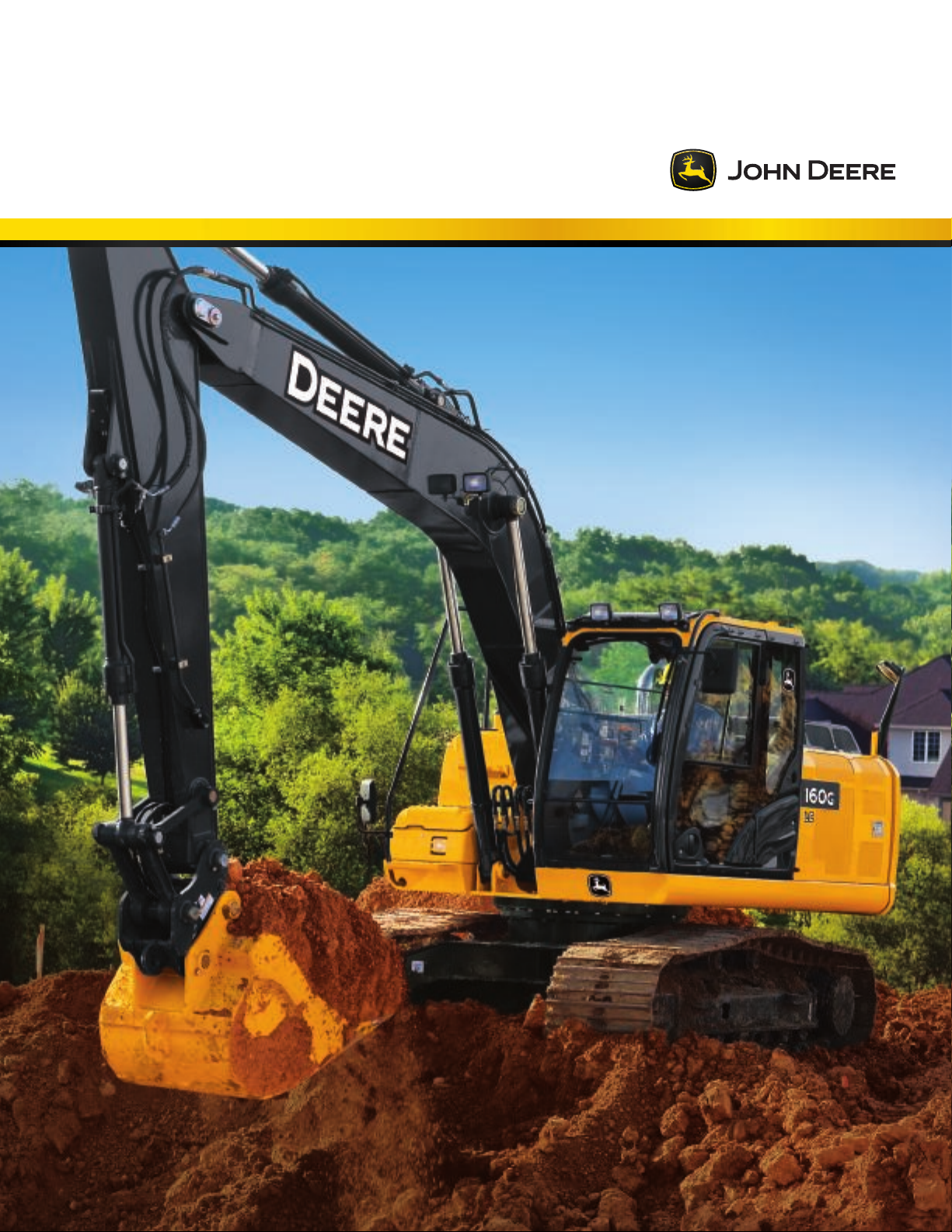
160G LC/180G LC
16–18 metric ton
Page 2
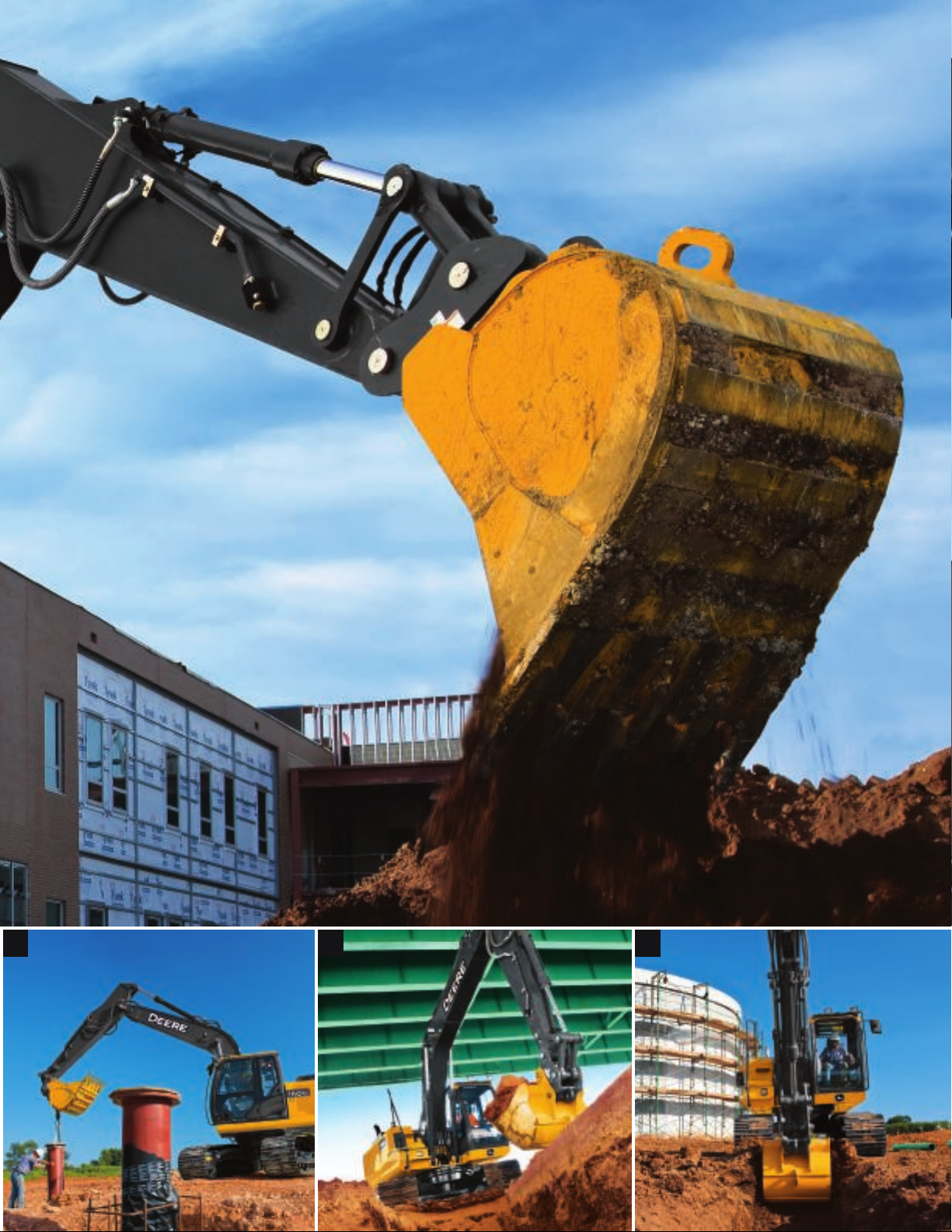
Seeking big productivity
in a mid-size package?
The enhanced 160G LC and all-new 180G LC will exceed your expectations. With impressive
arm force, dig force, and lift capacity, they pack plenty of ability into easy-to-transport
mid-size packages. Their more spacious and comfortable cabs come equipped with easy-tonavigate enhanced LCD monitors that let operators easily dial-in a wealth of machine info
and functionality. Rugged EPA Interim Tier 4/EU Stage IIIB John Deere PowerTech™ diesels
2
3
meet rigid emission regulations, enabling you to work, wherever there’s work — even in
nonattainment areas. And of course, you’ll enjoy typical John Deere smoothness, control, and
operating ease. Why settle for anything less?
Page 3
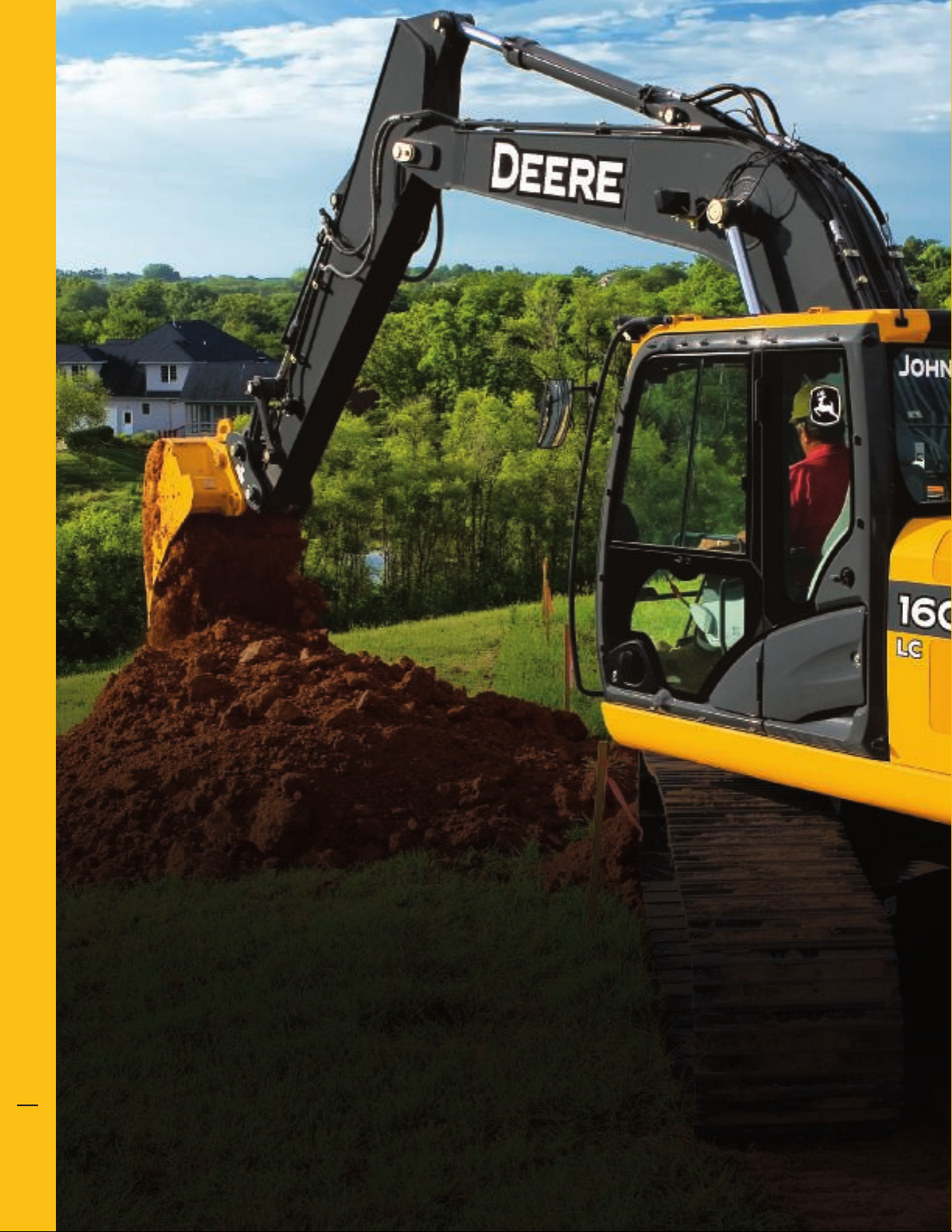
A longtime favorite because of its “load-and-go” versatility, the G-Series
version of our popular 160 is even more capable.
For those of you who said you’d like an even larger mid-size, there’s
the all-new 180G LC. Weighing nearly 2100 kg (4,632 lb.) more than its
smaller sibling, it also offers more reach, digging depth, lift capacity, and
arm and bucket dig forces.
The EPA IT4/EU Stage IIIB technology in our excavators is simple, fuel
efficient, fully integrated, and fully supported. It employs field-proven
cooled exhaust gas recirculation (EGR) for reducing NOX, and a diesel
particulate filter (© PF) and diesel oxidation catalyst (© OC) to reduce
particulate matter.
With John © eere WorkSight™, J© Link™ monitoring provides real-time
machine utilization and health data, plus location information. Fleet
Care proactively suggests maintenance to correct problems early
before they turn into costly downtime. And Service A© VISOR™ Remote
enables your dealer to read diagnostic codes, record performance data,
and even update software without a trip to the jobsite. It’s the most
comprehensive, easy-to-use suite of technology available for increasing
uptime and productivity while lowering operating costs. And it’s only
available from John © eere.
160G LC 180G LC
Net rated hp 90 kW (121 hp) 90 kW (121 hp)
Operating weight 18 017 kg (39,685 lb.) 20 120 kg (44,317 lb.)
Lift capacity 4267 kg (9,408 lb.) 5302 kg (11,690 lb.)
Maximum digging depth 6.49 m (21 ft. 4 in.) 7.07 m (23 ft. 2 in.)
Arm digging force 82 kN (18,508 lb.) 84 kN (18,825 lb.)
Bucket digging force 119 kN (26,665 lb.) 126 kN (28,244 lb.)
Page 4
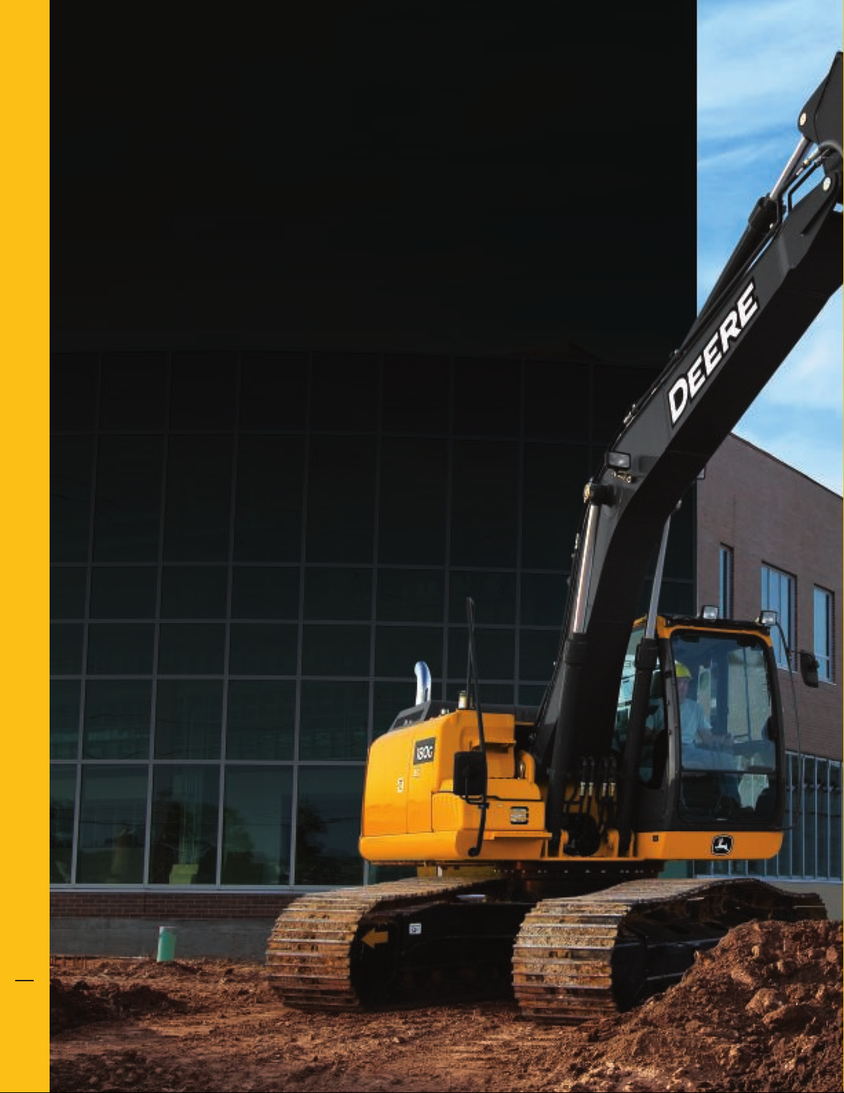
Mid-size, no compromise.
Whether you’re stockpiling overburden, excavating basements, loading
trucks, or placing pipe, the G-Series provide the muscle and finesse you need.
Their no-compromise Powerwise™ III hydraulic management systems yield
the pinpoint metering and smooth-as-silk low-effort control that have
become trademarks of our excavators. Plus, they’re highly maneuverable
— easily transported to the site, and navigating easily through a project’s
worth of tasks. So you can get in, get done, and get on to the next job.
Powerwise III perfectly balances engine
performance and hydraulic flow for predictable
operation. Three productivity modes allow
you to choose the digging style that fits the
job. High productivity delivers more power
and faster hydraulic response to move more
material. Power delivers smooth and balanced
metering for normal operation. Economy
reduces top speed and helps save fuel.
Choose from a variety of track widths, arm
lengths, buckets, high-flow auxiliary hydraulic
packages, and other options.
Machine Information Center (MIC) captures
and stores vital machine performance and
utilization data to help improve productivity,
uptime, and profit.
1. For work that requires extra finesse,
the G-Series’ short-throw low-effort
controls, unmatched metering, and
smooth multi-function operation
give the precision you need.
2. Generous flow, arm force, and swing
torque help speed cycles. So you can
do your best to stay on schedule
or ahead of the weather.
3. When the digging gets tough,
simply press the power-boost
button on the right-hand
control and muscle through.
4
5
Page 5
1 2 3
Page 6
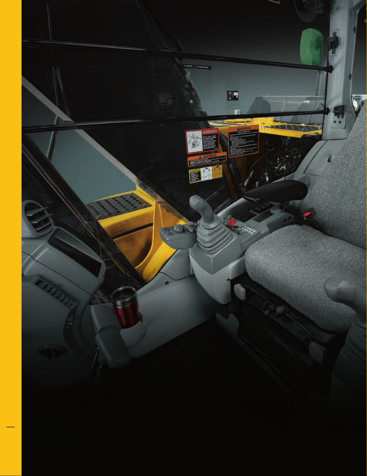
Operating ease takes a turn
for the better.
Now it’s easier than ever for your operators to “dial things up.” The G-Series’ refined monitor employs
a rotary control that makes it quick and easy to tap into an abundance of performance and convenience
6
7
functions and features. Operators will also appreciate the comfortable fabric-covered high-back seat
and increased legroom in the spacious, well-appointed cab. As always, unsurpassed all-round visibility,
low-effort joysticks, a highly efficient HVAC system, and numerous other amenities provide everything
your operators need to do their best work.
Page 7

With large self-cleaning steps and wide
entryways, getting in and out of our
excavators has never been easier.
Spacious cab is comfortable and noticeably
quiet. Silicone-filled mounts effectively
isolate operators from noise and vibration.
We’ve got your back with a sculpted
mechanical-suspension high-back seat.
Seat has 318 mm (12½ in.) of travel, sliding
together or independent of the joystick
console. So it won’t cramp an operator’s
style. For even more support and comfort,
opt for the air-suspension heated seat.
Ergonomically correct short-throw pilot
levers provide smooth, predictable fingertip
control with less movement or effort. Push
buttons in the right lever allow fingertip
control of auxiliary hydraulic flow for
operating attachments.
No shortage of storage in here. There’s a
place for a cooler, cup holders, and even a
hot/cold box that keeps beverages at just
the right temperature.
1
Standard boom/frame lights and cab/
boom-mounted options provide illumination
to extend your workday beyond normal
daylight hours.
1. Multi-language LCD monitor and rotary
dial provide intuitive access to a wealth of
information and functions. Just turn and
tap to select work mode, access operating
info, check maintenance intervals, source
diagnostic codes, adjust cab temperature,
and tune the radio. Plus much more.
2. Wide expanse of front and side glass,
narrow front cab posts, large overhead
glass, and numerous mirrors provide
virtually unobstructed all-around visibility.
If you need to see more, choose the
optional camera that displays the action
behind on the monitor.
3. Automatic, high-velocity bi-level climatecontrol system with automotive-style
adjustable louvers helps keep the glass
clear and the cab comfortable.
2
3
Page 8

Nothing runs
like a Deere,
because nothing
1. With large idlers, rollers, and strutted links,
is built like one.
Unlike some excavators that scream for attention, our G-Series’
hydraulically driven on-demand fans run only as fast or often as
needed. For reduced noise and fuel consumption. Their highly
efficient cooling systems keep things running cool, even in
high-trash environments and high altitudes. Other traditional
8
John Deere features include tungsten-carbide thermal-coated
the sealed and lubricated undercarriage
delivers long and reliable performance.
9
arm surfaces, oil-impregnated bushings, and welded-boom
bulkheads. For maximum uptime and long-term durability.
When you know how they’re built, you’ll run a Deere.
1
Page 9

A John Deere exclusive, three
welded bulkheads within the
boom resist torsional stress for
unsurpassed durability. Booms,
arms, and mainframes are so tough,
they’re warranted for three years or
10,000 hours.
Thick-plate single-sheet mainframe,
box-section track frames, and
industry-exclusive double-seal swing
bearing deliver rock-solid durability.
Wet-sleeve cylinder liners, monosteel pistons, and large-diameter
connecting rods ensure long-term
engine durability.
Reinforced resin thrust plates,
grooved bushings, and thermal-
coated bucket joints increase
arm and boom lube intervals to
500 hours.
Oil-impregnated bushings enhance
durability and extend grease
intervals to 500 hours for the armand-boom joint and 100 hours for
the bucket joint.
2. Highly efficient, heavy-duty cooling
system keeps things cool, even in tough
environments or high altitudes.
3. Reinforced © -channel side frames provide
maximum cab and component protection.
Tungsten-carbide coating creates
an extremely wear-resistant
surface to protect the allimportant bucket-to-arm joint.
4. Optional TK-Series bucket teeth are engineered
for maximum strength and impact absorption.
Hammer-free installation and removal
simplifies changes, minimizes downtime.
2 43
Page 10

Uncover all the
ways we keep
costs down.
Like all John Deere machines, the G-Series are
loaded with features that make them hassle-free
to service and low cost to maintain. Large, easy-toopen service doors and easy-access service points
make quick work of the daily routine. Remote-
mounted vertical oil and fuel filters and extended
engine and hydraulic oil-change intervals minimize
maintenance, too. Plus the Machine Information
Center (MIC), state-of-the-art LCD color monitor,
and fluid-sample ports help you make timely
decisions about machine upkeep — and enable
you to manage uptime and costs.
10
11
321
Page 11

Seamless diesel particulate filter (© PF)
cleaning happens automatically without
impacting machine productivity. The © PF
is easily removed through the top of the
engine compartment. Minimum service
interval is 4,500 hours and can be done
by your John © eere dealer.
Fluid-level sight gauges are conveniently
located and can be checked at a glance.
Large fuel tanks and 500- and 5,000hour engine and hydraulic oil-service
intervals decrease downtime for routine
maintenance.
Optional reversing fan back-blows cooler
cores to reduce debris buildup. It’s a welcome
addition that helps increase uptime.
Centralized lube banks place difficult-to-lube
zerks within easy reach. They make greasing
less messy and time consuming, too.
Auto-idle automatically reduces engine
speed when hydraulics aren’t in use. Auto-
shutdown further preserves precious fuel.
Convenient color-coded lubrication and
maintenance chart helps ensure that
nothing gets overlooked.
1. Easy-to-read LC© monitor tracks
scheduled maintenance intervals
and issues reminders. Should a
problem arise, it provides diagnostic
information to help decrease
downtime.
2. Fluid-sample and remote diagnostic
ports help speed preventative
maintenance and troubleshooting.
3. Vertical spin-on fuel and engine oil
filters are conveniently located in the
right rear compartment for simplified
ground-level servicing.
4. Fresh-air cab filter is quickly serviced
from outside the cab where it’s more
likely to get done.
5. Easy-to-reach dipstick and nearby
coolant reservoir make daily checks
and/or additions quick and easy.
6. Perforations in the side shields act as
a “first filter.” Anything that passes
through will also clear the 10-finper-inch cooler cores.
4 6
5
Page 12

160G LC
Engine 160G LC
Base engine for use in the U.S., U.S. Territories, and Canada Optional engine for use outside the U.S. and U.S. Territories
Manufacturer and Model John Deere PowerTech™ PVX John Deere PowerTech™ 4045H
Non-Road Emissions Standard EPA Interim Tier 4/EU Stage IIIB EPA Tier 3/EU Stage IIIA
Net Rated Power (ISO 9249) 90 kW (121 hp) at 2,200 rpm 90 kW (121 hp) at 1,900 rpm
Cylinders 4 4
Displacement 4.5 L (275 cu. in.) 4.5 L (275 cu. in.)
Off-Level Capacity 70% (35 deg.) 70% (35 deg.)
Aspiration Turbocharged, air-to-air charge-air cooler Turbocharged, air-to-air charge-air cooler
Cooling
Cool-on-demand hydraulic-driven, suction-type fan with remote-mounted drive
Powertrain
2-speed propel with automatic shift
Maximum Travel Speed
Low 3.4 km/h (2.1 mph)
High 5.3 km/h (3.3 mph)
Drawbar Pull 17 250 kg (38,030 lb.)
Hydraulics
Open center, load sensing
Main Pumps 2 variable-displacement axial-piston pumps
Maximum Rated Flow 191 L/m (50 gpm) x 2
Pilot Pump One gear
Maximum Rated Flow 33.6 L/m (8.9 gpm)
Pressure Setting 3930 kPa (570 psi)
System Operating Pressure
Circuits
Implement 34 336 kPa (4,980 psi)
Travel 34 336 kPa (4,980 psi)
Swing 34 336 kPa (4,980 psi)
Power Boost 38 000 kPa (5,511 psi)
Controls Pilot levers, short stroke, low-effort hydraulic pilot controls with shutoff lever
Cylinders
Bore Rod Diameter Stroke
Boom (2) 110 mm (4.33 in.) 80 mm (3.15 in.) 1110 mm (43.70 in.)
Arm (1) 120 mm (4.72 in.) 90 mm (3.54 in.) 1365 mm (53.74 in.)
Bucket (1) 105 mm (4.13 in.) 75 mm (2.95 in.) 935 mm (36.81 in.)
Electrical
Number of Batteries (12 volt) 2
Battery Capacity 1,400 CCA
Alternator Rating 100 amp
Work Lights 2 halogen (one mounted on boom, one on frame)
Undercarriage
Rollers (each side)
Carrier 2
Tra ck 7
Shoes, Triple Semi-Grousers (each side) 43
Tra ck
Adjustment Hydraulic
Guides Front and center
Chain Sealed and lubricated
Ground Pressure
Triple Semi-Grouser Shoes
600 mm (24 in.) 41 kPa (5.95 psi)
700 mm (28 in.) 35 kPa (5.08 psi)
12
13
Page 13

Swing Mechanism 160G LC
Speed 13.3 rpm
Torque 44 000 Nm (32,353 lb.-ft.)
Serviceability
Refill Capacities
Fuel Tank 320 L (84.5 gal.)
Cooling System 23.5 L (24.8 qt.)
Engine Oil with Filter 14.5 L (15 qt.)
Hydraulic Tank 125 L (33 gal.)
Hydraulic System 210 L (55.5 gal.)
Gearbox
Swing 6.2 L (6.6 qt.)
Propel (each) 6.8 L (7.2 qt.)
Pump Drive 0.9 L (1.0 qt.)
Operating Weights
With full fuel tank; 79-kg (175 lb.) operator; 914-mm (36 in.), 0.62-m
3
(0.81 cu. yd.), 623-kg (1,373 lb.) general-purpose bucket; 3.10-m (10 ft. 2 in.) arm; 3210-kg (7,077 lb.)
counterweight; and 700-mm (28 in.) triple semi-grouser shoes
Operating Weight 18 017 kg (39,685 lb.)
Component Weights
Undercarriage with Triple Semi-
Grouser Shoes
600 mm (24 in.) 6316 kg (13,912 lb.)
700 mm (28 in.) 6530 kg (14,383 lb.)
One-Piece Boom (with arm cylinder) 1300 kg (2,863 lb.)
Arm with Bucket Cylinder and Linkage
2.60 m (8 ft. 6 in.) 788 kg (1,736 lb.)
3.10 m (10 ft. 2 in.) 874 kg (1,925 lb.)
Boom-Lift Cylinders (2), Total Weight 306 kg (674 lb.)
914-mm (36 in.), 0.62-m
3
(0.81 cu. yd.)
623 kg (1,372 lb.)
Bucket
Counterweight, Standard 3210 kg (7,077 lb.)
Operating © imensions
Arm Length 2.60 m (8 ft. 6 in.) 3.10 m (10 ft.2 in.)
Arm Digging Force
SAE 90 kN (20,193 lb.) 79 kN (17,857 lb.)
ISO 93 kN (20,838 lb.) 82 kN (18,508 lb.)
Bucket Digging Force
SAE 105 kN (23,598 lb.) 105 kN (23,598 lb.)
ISO 119 kN (26,665 lb.) 119 kN (26,665 lb.)
Lifting Capacity Over Front at Ground
4269 kg (9,411 lb.) 4267 kg (9,408 lb.)
Level 6.1-m (20 ft. 0 in.) Reach (with
power boost)
A Maximum Reach 8.87 m (29 ft. 1 in.) 9.33 m (30 ft. 7 in.)
|
A
Maximum Reach at Ground Level 8.70 m (28 ft. 7 in.) 9.16 m (30 ft. 1 in.)
B Maximum Digging Depth 5.98 m (19 ft. 7 in.) 6.49 m (21 ft. 4 in.)
B|Maximum Digging Depth at 2.44-m
5.74 m (18 ft. 10 in.) 6.27 m (20 ft. 7 in.)
(8 ft. 0 in.) Flat Bottom
C Maximum Cutting Height 8.88 m (29 ft. 2 in.) 9.13 m (29 ft. 11 in.)
© Maximum Dumping Height 6.17 m (20 ft. 3 in.) 6.40 m (21 ft. 0 in.)
E Minimum Swing Radius 2.91 m (9 ft. 7 in.) 2.92 m (9 ft. 7 in.)
F Maximum Vertical Wall 5.16 m (16 ft. 11 in.) 5.69 m (18 ft. 8 in)
G Tail-Swing Radius 2.55 m (8 ft. 4 in.) 2.55 m (8 ft. 4 in.)
E
CENTERLINE OF SWING
C
B
B'
F
D
GROUND LINE
A'
A
G
Page 14

Machine Dimensions 160G LC
A Overall Length with Arm
2.60 m (8 ft. 6 in.) 8.62 m (28 ft. 3 in.)
3.10 m (10 ft. 2 in.) 8.65 m (28 ft. 5 in.)
B Overall Height with Arm
2.60 m (8 ft. 6 in.) 2.87 m (9 ft. 5 in.)
3.10 m (10 ft. 2 in.) 3.11 m (10 ft. 2 in.)
C Rear-End Length/Swing Radius 2.55 m (8 ft. 4 in.)
D © istance Between Idler/Sprocket Centerline 3.10 m (10 ft. 2 in.)
E Undercarriage Length 3.92 m (12 ft. 10 in.)
F Counterweight Clearance 1030 mm (3 ft. 5 in.)
G Upperstructure Width 2.50 m (8 ft. 2 in.)
H Cab Height 2.95 m (9 ft. 8 in.)
I Track Width with Triple Semi-Grouser Shoes 600 mm (24 in.) / 700 mm (28 in.)
J Gauge Width 1.99 m (6 ft. 6 in.)
K Ground Clearance 470 mm (19 in.)
L Overall Width with Triple Semi-Grouser Shoes
600 mm (24 in.) 2.59 m (8 ft. 6 in.)
700 mm (28 in.) 2.69 m (8 ft. 10 in.)
14
15
G
C
F
H
K
I
J
L
B
D
E
A
Lift Capacities
Boldface type indicates hydraulically limited capacity; lightface type indicates stability-limited capacities, in kg (lb.). Ratings at bucket lift hook; machine equipped with 528-kg (1,164 lb.)
bucket, standard counterweight, and standard gauge; and situated on firm, level, uniform supporting surface. Total load includes weight of cables, hook, etc. Figures do not exceed 87 percent
of hydraulic capacities or 75 percent of weight needed to tip machine. All lift capacities are based on ISO 10567 (with power boost).
Load Point
Height
Horizontal
Distance from
Centerline
of Rotation
With 2.60-m (8 ft. 6 in.) arm and 600-mm (24 in.) triple semi-grouser shoes
6.0 m
(20 ft.)
4.5 m
(15 ft.)
3.0 m
(10 ft.)
1.5 m
(5 ft.)
Ground
Line
–1.5 m
(–5 ft.)
–3.0 m
(–10 ft.)
With 2.60-m (8 ft. 6 in.) arm and 700-mm (28 in.) triple semi-grouser shoes
6.0 m
(20 ft.)
4.5 m
(15 ft.)
3.0 m
(10 ft.)
1.5 m
(5 ft.)
Ground
Line
–1.5 m
(–5 ft.)
–3.0 m
(–10 ft.)
1.5 m (5 ft.) 3.0 m (10 ft.) 4.5 m (15 ft.) 6.0 m (20 ft.) 7.5 m (25 ft.)
Over Front
5300
(11,850)
9850
(22,250)
5300
(11,850)
9850
(22,250)
Over Side
5300
(11,850)
9850
(22,250)
5300
(11,850)
9850
(22,250)
Over Front
8400
(17,850)
5800
(13,450)
9950
(22,800)
10 550
(22,850)
8400
(17,850)
5800
(13,450)
9950
(22,800)
10 550
(22,850)
Over Side
8400
(17,850)
5800
(13,450)
7450
(15,950)
7600
(16,300)
8400
(17,850)
5800
(13,450)
7650
(16,400)
7800
(16,700)
Over Front
4100
(8,900)
5400
(11,700)
6800
(14,650)
6600
(14,200)
6550
(14,050)
6600
(14,200)
4100
(8,900)
5400
(11,700)
6800
(14,650)
6800
(14,600)
6700
(14,450)
6800
(14,600)
Over Side
4100
(8,900)
4450
(9,550)
4100
(8,850)
3900
(8,450)
3850
(8,300)
3900
(8,450)
4100
(8,900)
4550
(9,800)
4200
(9,100)
4050
(8,650)
3950
(8,550)
4050
(8,700)
Over Front
2850 2850
3850
(8,400)
4400
(9,550)
4300
(9,200)
4150
(8,950)
4100
(8,850)
2850 2850
3850
(8,400)
4400
(9,550)
4400
(9,450)
4300
(9,200)
4250
(9,150)
Over Side
2900
(6,250)
2750
(5,950)
2650
(5,650)
2500
(5,400)
2500
(5,350)
3000
(6,400)
2850
(6,150)
2700
(5,800)
2600
(5,600)
2550
(5,500)
Over Front
Over Side
Page 15

Lift Capacities (continued) 160G LC
Boldface type indicates hydraulically limited capacity; lightface type indicates stability-limited capacities, in kg (lb.). Ratings at bucket lift hook; machine equipped with 528-kg (1,164 lb.) bucket,
standard counterweight, and standard gauge; and situated on firm, level, uniform supporting surface. Total load includes weight of cables, hook, etc. Figures do not exceed 87 percent of hydraulic
capacities or 75 percent of weight needed to tip machine. All lift capacities are based on ISO 10567 (with power boost).
Load Point
1.5 m (5 ft.) 3.0 m (10 ft.) 4.5 m (15 ft.) 6.0 m (20 ft.) 7.5 m (25 ft.)
Height
Horizontal
Distance from
Centerline
of Rotation
Over Front
Over Side
Over Front
Over Side
Over Front
Over Side
Over Front
Over Side
Over Front
Over Side
With 3.10-m (10 ft. 2 in.) arm and 600-mm (24 in.) triple semi-grouser shoes
6.0 m
(20 ft.)
4.5 m
(15 ft.)
3.0 m
(10 ft.)
1.5 m
(5 ft.)
Ground
Line
–1.5 m
(–5 ft.)
–3.0 m
(–10 ft.)
–4.5 m
(–15 ft.)
4700
(10,550)
8250
(18,600)
4700
(10,550)
8250
(18,600)
6950
(14,800)
7100
(17,200)
6400
(14,750)
9200
(21,000)
11 200
(24,200)
8900
(19,050)
6950
(14,800)
7100
(16,750)
6400
(14,750)
7350
(15,750)
7450
(15,950)
7700
(16,600)
4800
(10,400)
6300
(13,600)
6600
(14,200)
6500
(13,950)
6500
(14,000)
5850
(12,300)
4500
(9,750)
4150
(8,950)
3900
(8,400)
3800
(8,200)
3850
(8,250)
4000
(8,650)
2950
(6,150)
3400
(7,450)
4000
(8,700)
4300
(9,250)
4150
(8,900)
4100
(8,750)
4100
(8,850)
2950
(6,150)
2950
(6,300)
2800
(6,000)
2650
(5,650)
2500
(5,400)
2450
(5,250)
2450
(5,300)
2900
(5,750)
2950
(6,350)
2900
(6,200)
1850
(4,000)
1800
(3,850)
1750
(3,700)
With 3.10-m (10 ft. 2 in.) arm and 700-mm (28 in.) triple semi-grouser shoes
6.0 m
(20 ft.)
4.5 m
(15 ft.)
3.0 m
(10 ft.)
1.5 m
(5 ft.)
Ground
Line
–1.5 m
(–5 ft.)
–3.0 m
(–10 ft.)
–4.5 m
(–15 ft.)
4700
(10,550)
8250
(18,600)
4700
(10,550)
8250
(18,600)
6950
(14,800)
7100
(17,200)
6400
(14,750)
9200
(21,000)
11 200
(24,200)
8900
(19,050)
6950
(14,800)
7100
(17,200)
6400
(14,750)
7550
(16,150)
7650
(16,400)
7900
(17,000)
4800
(10,400)
6300
(13,600)
6800
(14,600)
6650
(14,350)
6700
(14,400)
5850
(12,300)
4650
(10,000)
4250
(9,200)
4000
(8,650)
3900
(8,450)
3950
(8,500)
4100
(8,900)
2950
(6,150)
3400
(7,450)
4000
(8,700)
4400
(9,500)
4250
(9,150)
4200
(9,000)
4200
(9,100)
2950
(6,150)
3000
(6,500)
2900
(6,200)
2700
(5,850)
2600
(5,550)
2500
(5,400)
2550
(5,500)
2900
(5,750)
3050
(6,550)
3000
(6,400)
1900
(4,100)
1850
(3,950)
1800
(3,850)
Buckets
A full line of buckets is offered to meet a wide variety of applications. © igging forces are with power boost. Buckets are equipped with John © eere Fanggs™ or ESCO teeth standard. Replaceable
cutting edges and a variety of teeth are available through John © eere Parts. Optional side cutters add 150 mm (6 in.) to bucket widths. Capacities are SAE heaped ratings.
Type Bucket
General Purpose
High Capacity
Bucket Width
mm in. m
610
24
Bucket Capacity
3
cu. yd. kg lb. kN lb. kN lb. kN lb. mm in.
0.41 0.54
Bucket Weight Bucket Dig Force
Arm Dig Force
2.60 m (8 ft. 6 in.)
Arm Dig Force
3.10 m (10 ft. 2 in.) Bucket Tip Radius
491 1,081 97.7 21,966 87.8 19,744 78.5 17,648 1463 57.61
Number
of Teeth
4
760 30 0.55 0.72 569 1,253 97.7 21,966 87.8 19,744 78.5 17,648 1463 57.61 4
915 36 0.70 0.91 655 1,443 97.7 21,966 87.8 19,744 78.5 17,648 1463 57.61 5
1065 42 0.85 1.11 733 1,615 97.7 21,966 87.8 19,744 78.5 17,648 1463 57.61 5
Heavy © uty 610 24 0.37 0.48 493 1,086 106.0 23,832 90.4 20,320 80.5 18,105 1349 53.10 4
760 30 0.50 0.65 554 1,221 106.0 23,832 90.4 20,320 80.5 18,105 1349 53.10 4
915 36 0.62 0.81 623 1,373 106.0 23,832 90.4 20,320 80.5 18,105 1349 53.10 5
1065 42 0.76 0.99 685 1,508 106.0 23,832 90.4 20,320 80.5 18,105 1349 53.10 5
© itching 1525 60 0.63 0.83 484 1,066 152.9 34,378 101.0 22,712 88.8 19,971 935 36.81 0
Bucket Selection Guide*
1.5
(2.00)
1.3
(1.75)
1.2
3
(1.50)
1.0
(1.25)
BUCKET SIZE m (cu. yd.)
(1.0)
(0.75)
lb./cu. yd.
3
kg/m
0.8
0.6
Deere 3.10-m (10 ft. 2 in.) Arm
1,200 1,400 1,800 2,400 2,800 3,000 3,600
700 800 900 1000 1100 1200
1,600 3,400
Deere 2.60-m (8 ft. 6 in.) Arm
2,000 2,200 2,600 3,200
1300
1400 1500 1600 1700 1800 1900
2000
2100
*
Contact your John Deere dealer for optimum bucket and attachment selections. These recommendations are for general conditions and average use. Does not include
optional equipment such as thumbs or couplers. Larger buckets may be possible when using light materials, for flat and level operations, less compacted materials, and
volume loading applications such as mass-excavation applications in ideal conditions. Smaller buckets are recommended for adverse conditions such as off-level applications, rocks, and uneven surfaces. Bucket capacity indicated is SAE heaped.
Wet Peat
Topsoil
Coal
Caliche
Shale
Dry Sand
Dry Clay
Limestone
Wet Earth
Wet Clay, Granite
Moist Sand
Wet Sand
Wet Sand, Gravel
Page 16

16
180G LC
Engine 180G LC
Base engine for use in the U.S., U.S. Territories, and Canada Optional engine for use outside the U.S. and U.S. Territories
Manufacturer and Model John Deere PowerTech™ PVX John Deere PowerTech™ 4045H
Non-Road Emissions Standard EPA Interim Tier 4/EU Stage IIIB EPA Tier 3/EU Stage IIIA
Net Rated Power (ISO 9249) 90 kW (121 hp) at 2,200 rpm 90 kW (121 hp) at 1,900 rpm
Cylinders 4 4
Displacement 4.5 L (275 cu. in.) 4.5 L (275 cu. in.)
Off-Level Capacity 70% (35 deg.) 70% (35 deg.)
Aspiration Turbocharged, air-to-air charge-air cooler Turbocharged, air-to-air charge-air cooler
Cooling
Cool-on-demand hydraulic-driven, suction-type fan with remote-mounted drive
Powertrain
2-speed propel with automatic shift
Maximum Travel Speed
Low 3.4 km/h (2.1 mph)
High 5.3 km/h (3.3 mph)
Drawbar Pull 17 250 kg (38,030 lb.)
Hydraulics
Open center, load sensing
Main Pumps 2 variable-displacement axial-piston pumps
Maximum Rated Flow 191 L/m (50 gpm) x 2
Pilot Pump One gear
Maximum Rated Flow 33.6 L/m (8.9 gpm)
Pressure Setting 3930 kPa (570 psi)
System Operating Pressure
Circuits
Implement 34 336 kPa (4,980 psi)
Travel 34 336 kPa (4,980 psi)
Swing 34 336 kPa (4,980 psi)
Power Boost 38 000 kPa (5,511 psi)
Controls Pilot levers, short stroke, low-effort hydraulic pilot controls with shutoff lever
Cylinders
Bore Rod Diameter Stroke
Boom (2) 120 mm (4.72 in.) 85 mm (3.35 in.) 1123 mm (44.21 in.)
Arm (1) 125 mm (4.92 in.) 90 mm (3.54 in.) 1371 mm (53.98 in.)
Bucket (1) 105 mm (4.13 in.) 75 mm (2.95 in.) 1060 mm (41.73 in.)
Electrical
Number of Batteries (12 volt) 2
Battery Capacity 1,400 CCA
Alternator Rating 100 amp
Work Lights 2 halogen (one mounted on boom, one on frame)
Undercarriage
Rollers (each side)
Carrier 2
Tra ck 7
Shoes, Triple Semi-Grousers (each side) 46
Tra ck
Adjustment Hydraulic
Guides Center
Chain Sealed and lubricated
Ground Pressure
Triple Semi-Grouser Shoes
600 mm (24 in.) 41 kPa (5.95 psi)
700 mm (28 in.) 36 kPa (5.22 psi)
800 mm (32 in.) 32 kPa (4.64 psi)
17
Page 17

Swing Mechanism 180G LC
Speed 12.8 rpm
Torque 50 000 Nm (36,765 lb.-ft.)
Serviceability
Refill Capacities
Fuel Tank 320 L (84.5 gal.)
Cooling System 23.5 L (24.8 qt.)
Engine Oil with Filter 14.5 L (15 qt.)
Hydraulic Tank 125 L (33 gal.)
Hydraulic System 210 L (55.5 gal.)
Gearbox
Swing 6.2 L (6.6 qt.)
Propel (each) 6.8 L (7.2 qt.)
Pump Drive 0.9 L (1.0 qt.)
Operating Weights
With full fuel tank; 79-kg (175 lb.) operator; 1067-mm (42 in.), 0.83-m
3
(1.09 cu. yd.), 785-kg (1,731 lb.) general-purpose bucket; 3.21-m (10 ft. 6 in.) arm; 3910-kg (8,620 lb.)
counterweight; and 700-mm (28 in.) triple semi-grouser shoes
Operating Weight 20 120 kg (44,317 lb.)
Component Weights
Undercarriage with Triple Semi-
Grouser Shoes
600 mm (24 in.) 6752 kg (14,873 lb.)
700 mm (28 in.) 7143 kg (15,733 lb.)
800 mm (32 in.) 7437 kg (16,381 lb.)
One-Piece Boom (with arm cylinder) 1566 kg (3,449 lb.)
Arm with Bucket Cylinder and Linkage
2.71 m (8 ft. 10 in.) 881 kg (1,941 lb.)
3.21 m (10 ft. 6 in.) 946 kg (2,084 lb.)
Boom-Lift Cylinders (2), Total Weight 326 kg (718 lb.)
1067-mm (42 in.), 0.83-m
3
(1.09 cu. yd.)
785 kg (1,731 lb.)
Bucket
Counterweight, Standard 3910 kg (8,620 lb.)
Operating © imensions
Arm Length 2.71 m (8 ft. 10 in.) 3.21 m (10 ft. 6 in.)
Arm Digging Force
SAE 91 kN (20,496 lb.) 81 kN (18,240 lb.)
ISO 95 kN (21,282 lb.) 84 kN (18,825 lb.)
Bucket Digging Force
SAE 113 kN (25,311 lb.) 113 kN (25,311 lb.)
ISO 126 kN (28,244 lb.) 126 kN (28,244 lb.)
Lifting Capacity Over Front at Ground
5287 kg (11,656 lb.) 5302 kg (11,690 lb.)
Level 6.1-m (20 ft. 0 in.) Reach (with
power boost)
A Maximum Reach 9.43 m (30 ft. 11 in.) 9.94 m (32 ft. 7 in.)
|
A
Maximum Reach at Ground Level 9.27 m (30 ft. 5 in.) 9.79 m (32 ft. 1 in.)
B Maximum Digging Depth 6.57 m (21 ft. 7 in.) 7.07 m (23 ft. 2 in.)
B|Maximum Digging Depth at 2.44-m
6.32 m (20 ft. 9 in.) 6.87 m (22 ft. 6 in.)
(8 ft. 0 in.) Flat Bottom
C Maximum Cutting Height 9.40 m (30 ft. 10 in.) 9.79 m (32 ft. 1 in.)
© Maximum Dumping Height 6.57 m (21 ft. 7 in.) 6.93 m (22 ft. 9 in.)
E Minimum Swing Radius 3.13 m (10 ft. 3 in.) 3.13 m (10 ft. 3 in.)
F Maximum Vertical Wall 5.55 m (18 ft. 3 in.) 6.28 m (20 ft. 7 in.)
G Tail-Swing Radius 2.55 m (8 ft. 4 in.) 2.55 m (8 ft. 4 in.)
E
CENTERLINE OF SWING
C
B
B'
F
D
GROUND LINE
A'
A
G
Page 18

Machine Dimensions 180G LC
A Overall Length with Arm
2.71 m (8 ft. 10 in.) 9.04 m (29 ft. 8 in.)
3.21 m (10 ft. 6 in.) 9.04 m (29 ft. 8 in.)
B Overall Height with Arm
2.71 m (8 ft. 10 in.) 3.08 m (10 ft. 1 in.)
3.21 m (10 ft. 6 in.) 3.39 m (11 ft. 1 in.)
C Rear-End Length/Swing Radius 2.55 m (8 ft. 4 in.)
D Distance Between Idler/Sprocket Centerline 3.37 m (11 ft. 1 in.)
E Undercarriage Length 4.17 m (13 ft. 8 in.)
F Counterweight Clearance 1030 mm (3 ft. 5 in.)
G Upperstructure Width 2.50 m (8 ft. 2 in.)
H Cab Height 2.95 m (9 ft. 8 in.)
I Track Width with Triple Semi-Grouser Shoes 600 mm (24 in.) / 700 mm (28 in.) / 800 mm (32 in.)
J Gauge Width 2.20 m (7 ft. 3 in.)
K Ground Clearance 450 mm (18 in.)
L Overall Width with Triple Semi-Grouser Shoes
600 mm (24 in.) 2.80 m (9 ft. 2 in.)
700 mm (28 in.) 2.90 m (9 ft. 6 in.)
800 mm (32 in.) 3.00 m (9 ft. 10 in.)
H
G
B
C
F
18
19
K
I
J
A
D
E
L
Lift Capacities
Boldface type indicates hydraulically limited capacity; lightface type indicates stability-limited capacities, in kg (lb.). Ratings at bucket lift hook; machine equipped with 600-kg (1,323 lb.)
bucket, standard counterweight, and standard gauge; and situated on firm, level, uniform supporting surface. Total load includes weight of cables, hook, etc. Figures do not exceed
87 percent of hydraulic capacities or 75 percent of weight needed to tip machine. All lift capacities are based on ISO 10567 (with power boost).
Load Point
Height
Horizontal
Distance from
Centerline
of Rotation
With 2.71-m (8 ft. 10 in.) arm and 700-mm (28 in.) triple semi-grouser shoes
6.0 m
(20 ft.)
4.5 m
(15 ft.)
3.0 m
(10 ft.)
1.5 m
(5 ft.)
Ground
Line
–1.5 m
(–5 ft.)
–3.0 m
(–10 ft.)
–4.5 m
(–15 ft.)
With 3.21-m (10 ft. 6 in.) arm and 600-mm (24 in.) triple semi-grouser shoes
6.0 m
(20 ft.)
4.5 m
(15 ft.)
3.0 m
(10 ft.)
1.5 m
(5 ft.)
Ground
Line
–1.5 m
(–5 ft.)
–3.0 m
(–10 ft.)
–4.5 m
(–15 ft.)
1.5 m (5 ft.) 3.0 m (10 ft.) 4.5 m (15 ft.) 6.0 m (20 ft.) 7.5 m (25 ft.)
Over Front
4700
(10,500)
8800
(19,850)
4000
(8,950)
7250
(16,350)
11 700
(26,500)
Over Side
4700
(10,500)
8800
(19,850)
4000
(8,950)
7250
(16,350)
11 700
(26,500)
Over Front
4350
(10,150)
8300
(18,950)
12 750
(27,650)
10 150
(21,700)
8950
(19,000)
4700
(10,900)
7450
(17,000)
11 750
(26,900)
11 300
(24,300)
Over Side
4350
(10,150)
8300
(18,950)
9750
(20,950)
10 100
(21,700)
8950
(19,000)
4700
(10,900)
7450
(17,000)
9450
(20,200)
9700
(20,850)
Over Front
4850
(10,450)
6550
(14,050)
8200
(17,700)
8500
(18,200)
8400
(18,000)
8450
(18,150)
6900
(14,600)
5850
(12,600)
7650
(16,500)
8350
(17,900)
8200
(17,600)
8200
(17,600)
7700
(16,500)
Over Side
4850
(10,450)
5600
(12,050)
5200
(11,200)
4950
(10,650)
4900
(10,500)
4950
(10,650)
5150
(11,100)
5600
(12,100)
5150
(11,150)
4850
(10,500)
4750
(10,200)
4750
(10,250)
4900
(10,600)
Over Front
4000
(8,850)
4400
(9,550)
5150
(11,150)
5450
(11,700)
5300
(11,400)
5250
(11,250)
5250
(11,350)
3450
(7,650)
3900
(8,550)
4700
(10,250)
5350
(11,550)
5200
(11,150)
5100
(10,950)
5100
(10,950)
Over Side
3800
(8,150)
3700
(7,950)
3550
(7,600)
3350
(7,200)
3200
(6,900)
3150
(6,750)
3200
(6,850)
3450
(7,650)
3700
(7,950)
3500
(7,550)
3300
(7,100)
3150
(6,750)
3050
(6,550)
3050
(6,550)
Over Front
(8,350)
(8,150)
(8,000)
(6,850)
(8,200)
(7,950)
(7,800)
(7,700)
3900
3800
3700
3350
3800
3700
3600
3600
Over Side
2400
(5,150)
2300
(4,950)
2250
(4,850)
2450
(5,200)
2350
(5,050)
2250
(4,850)
2150
(4,650)
2150
(4,600)
Page 19

Lift Capacities (continued) 180G LC
Boldface type indicates hydraulically limited capacity; lightface type indicates stability-limited capacities, in kg (lb.). Ratings at bucket lift hook; machine equipped with 600-kg (1,323 lb.)
bucket, standard counterweight, and standard gauge; and situated on firm, level, uniform supporting surface. Total load includes weight of cables, hook, etc. Figures do not exceed 87 percent
of hydraulic capacities or 75 percent of weight needed to tip machine. All lift capacities are based on ISO 10567 (with power boost).
Load Point
1.5 m (5 ft.) 3.0 m (10 ft.) 4.5 m (15 ft.) 6.0 m (20 ft.) 7.5 m (25 ft.)
Height
Horizontal
Distance from
Centerline
of Rotation
Over Front
Over Side
Over Front
Over Side
Over Front
Over Side
Over Front
Over Side
Over Front
Over Side
With 3.21-m (10 ft. 6 in.) arm and 700-mm (28 in.) triple semi-grouser shoes
6.0 m
(20 ft.)
4.5 m
(15 ft.)
3.0 m
(10 ft.)
1.5 m
(5 ft.)
Ground
Line
–1.5 m
(–5 ft.)
–3.0 m
(–10 ft.)
–4.5 m
(–15 ft.)
4000
(8,950)
7250
(16,350)
11 700
(26,500)
4000
(8,950)
7250
(16,350)
11 700
(26,500)
8950
(19,000)
4700
(10,900)
7450
(17,000)
11 750
(26,900)
11 300
(24,300)
8950
(19,000)
4700
(10,900)
7450
(17,000)
9600
(20,600)
9900
(21,250)
5850
(12,600)
7650
(16,500)
8500
(18,250)
8350
(17,950)
8400
(18,000)
7700
(16,500)
5700
(12,300)
5250
(11,350)
4950
(10,700)
4850
(10,450)
4850
(10,450)
5000
(10,800)
3450
(7,650)
3900
(8,550)
4700
(10,250)
5500
(11,800)
5300
(11,400)
5200
(11,150)
5200
(11,200)
3450
(7,650)
3750
(8,100)
3550
(7,700)
3350
(7,250)
3200
(6,850)
3100
(6,700)
3100
(6,700)
3350
(6,850)
3900
(8,350)
3800
(8,150)
3700
(7,950)
3650
(7,850)
2500
(5,350)
2400
(5,150)
2300
(4,950)
2250
(4,800)
2200
(4,700)
With 3.21-m (10 ft. 6 in.) arm and 800-mm (32 in.) triple semi-grouser shoes
6.0 m
(20 ft.)
4.5 m
(15 ft.)
3.0 m
(10 ft.)
1.5 m
(5 ft.)
Ground
Line
–1.5 m
(–5 ft.)
–3.0 m
(–10 ft.)
–4.5 m
(–15 ft.)
4000
(8,950)
7250
(16,350)
11 700
(26,500)
4000
(8,950)
7250
(16,350)
11 700
(26,500)
8950
(19,000)
4700
(10,900)
7450
(17,000)
11 750
(26,900)
11 300
(24,300)
8950
(19,000)
4700
(10,900)
7450
(17,000)
9750
(20,900)
10 050
(21,500)
5850
(12,600)
7650
(16,500)
8650
(18,500)
8500
(18,200)
8500
(18,250)
7700
(16,500)
5800
(12,500)
5350
(11,500)
5050
(10,850)
4950
(10,600)
4950
(10,650)
5100
(10,950)
3450
(7,650)
3900
(8,550)
4700
(10,250)
5550
(11,950)
5400
(11,550)
5300
(11,350)
5300
(11,350)
3450
(7,650)
3800
(8,200)
3600
(7,800)
3400
(7,350)
3250
(7,000)
3150
(6,800)
3150
(6,800)
3350
(6,850)
3950
(8,500)
3850
(8,250)
3750
(8,100)
3700
(8,000)
2550
(5,400)
2450
(5,250)
2350
(5,050)
2250
(4,850)
2250
(4,800)
Buckets
A full line of buckets is offered to meet a wide variety of applications. © igging forces are with power boost. Buckets are equipped with John © eere Fanggs™ or ESCO teeth standard. Replaceable
cutting edges and a variety of teeth are available through John © eere Parts. Optional side cutters add 150 mm (6 in.) to bucket widths. Capacities are SAE heaped ratings.
Type Bucket
Bucket Width
Bucket Capacity Bucket Weight
mm in. m
3
cu. yd. kg lb. kN lb. kN lb. kN lb. mm in.
Bucket Dig Force
(SAE)
Arm Dig Force
2.71 m (8 ft. 10 in.)
Arm Dig Force
3.21 m (10 ft. 6 in.) Bucket Tip Radius
Number
of Teeth
Heavy © uty 760 30 0.54 0.71 622 1,369 135.9 30,554 130.2 29,271 107.1 24,071 1463 57.61 4
915 36 0.69 0.90 708 1,559 135.9 30,554 130.2 29,271 107.1 24,071 1463 57.61 5
1065 42 0.83 1.09 786 1,731 135.9 30,554 130.2 29,271 107.1 24,071 1463 57.61 5
1220 48 0.99 1.29 872 1,921 135.9 30,554 130.2 29,271 107.1 24,071 1463 57.61 6
Heavy © uty
High Capacity 915 36 0.74 0.97 809 1,782 135.0 30,349 129.9 29,197 106.8 24,016 1473 58.0 5
1065 42 0.91 1.19 886 1,951 135.0 30,349 129.9 29,197 106.8 24,016 1473 58.0 5
Bucket Selection Guide*
1.7
(2.25)
1.5
(2.00)
1.3
(1.75)
3
1.2
(1.50)
1.0
(1.25)
0.8
BUCKET SIZE m (cu. yd.)
(1.00)
0.6
(0.75)
1,200 1,400 1,800 2,400 2,800 3,000 3,600
lb./cu. yd.
3
kg/m
700 800 900 1000 1100 1200
Deere 2.71-m (8 ft. 10 in.) Arm
Deere 3.21-m (10 ft. 6 in.) Arm
1,600 3,400
2,000 2,200 2,600 3,200
1300
1400 1500 1600 1700 1800 1900
2000
2100
*
Contact your John Deere dealer for optimum bucket and attachment selections. These recommendations are for general conditions and average use. Does not include
optional equipment such as thumbs or couplers. Larger buckets may be possible when using light materials, for flat and level operations, less compacted materials, and
volume loading applications such as mass-excavation applications in ideal conditions. Smaller buckets are recommended for adverse conditions such as off-level applications, rocks, and uneven surfaces. Bucket capacity indicated is SAE heaped.
Wet Peat
Topsoil
Coal
Caliche
Shale
Dry Sand
Dry Clay
Limestone
Wet Earth
Wet Clay, Granite
Moist Sand
Wet Sand
Wet Sand, Gravel
Page 20

Additional equipment
Key: ● Standard ▲ Optional or special See your John Deere dealer for further information.
160G LC180G LC
● ●
● ●
● ●
● ●
● ●
● ●
● ●
● ●
● ●
● ●
● ●
● ●
● ●
● ●
● ●
● ●
▲ ▲
▲ ▲
▲ ▲
▲ ▲
● ●
● ●
● ●
● ●
● ●
● ●
● ●
▲ ▲
▲ ▲
▲ ▲
▲ ▲
▲ ▲
▲ ▲
● ●
● ●
● ●
● ●
● ●
● ●
● ●
▲ ▲
▲ ▲
▲
Engine
Auto-idle system
Automatic belt-tension device
Batteries (2 – 12 volt)
Coolant recovery tank
© ual-element dry-type air filter
Electronic engine control
Enclosed fan guard (conforms to SAE
J1308)
Engine coolant to –37 deg. C (–34 deg. F)
Fuel filter with water separator
Full-flow oil filter
Turbocharger with charge air cooler
Cool-on-demand hydraulic-driven fan
500-hour engine-oil-change interval
70% (35 deg.) off-level capability
Engine-oil-sampling valve
Programmable auto shutdown
Chrome exhaust stack
Severe-duty fuel filter
Hydraulic fan reverser
Engine coolant heater
Hydraulic System
Reduced-drift valve for boom down,
arm in
Auxiliary hydraulic valve section
Spring-applied, hydraulically released
automatic swing brake
Auxiliary hydraulic-flow adjustments
through monitor
Auto power lift
5,000-hour hydraulic-oil-change interval
Hydraulic-oil-sampling valve
Auxiliary hydraulic lines
Auxiliary pilot and electric controls
Hydraulic filter restriction indicator kit
Load-lowering control device
Single-pedal propel control
Control pattern-change valve
Undercarriage
Planetary drive with axial piston motors
Propel motor shields
Spring-applied, hydraulically released
automatic propel brake
Track guides, front idler and center
2-speed propel with automatic shift
Upper carrier rollers (2)
Sealed and lubricated track chain
Triple semi-grouser shoes, 600 mm (24 in.)
Triple semi-grouser shoes, 700 mm (28 in.)
Triple semi-grouser shoes, 800 mm (32 in.)
160G LC180G LC
● ●
● ●
● ●
● ●
● ●
● ●
● ●
● ●
● ●
● ●
▲
▲
▲
▲
▲ ▲
▲ ▲
▲ ▲
▲ ▲
● ●
● ●
● ●
● ●
● ●
● ●
● ●
● ●
● ●
● ●
● ●
● ●
● ●
● ●
● ●
● ●
● ●
Upperstructure
Right-hand, left-hand, and counterweight mirrors
Vandal locks with ignition key: Cab door /
Service doors / Toolbox
Debris-screening side panel
Remote-mounted engine oil and fuel
filters
Front Attachments
Centralized lubrication system
Dirt seals on all bucket pins
Less boom and arm
Oil-impregnated bushings
Reinforced resin thrust plates
Tungsten carbide thermal coating on
arm-to-bucket joint
Arm, 2.60 m (8 ft. 6 in.)
Arm, 2.71 m (8 ft. 10 in.)
Arm, 3.10 m (10 ft. 2 in.)
Arm, 3.21 m (10 ft. 6 in.)
Attachment quick-couplers
Boom cylinder with plumbing to mainframe less boom and arm
Buckets: Ditching / Heavy duty / Heavyduty high capacity / Side cutters and teeth
Material clamps
Operator’s Station
Meets ISO 12117-2 for ROPS
Adjustable independent-control positions
(levers-to-seat, seat-to-pedals)
AM/FM radio
Auto climate control/air conditioner/
heater/pressurizer
Built-in Operator’s Manual storage
compartment and manual
Cell-phone power outlet, 12 volt, 60 watt,
5 amp
Coat hook
Deluxe suspension cloth seat with
100-mm (4 in.) adjustable armrests
Floor mat
Front windshield wiper with intermittent
speeds
Gauges (illuminated): Engine coolant /
Fuel
Horn, electric
Hour meter, electric
Hydraulic shutoff lever, all controls
Hydraulic warm-up control
Interior light
Large cup holder
160G LC180G LC
● ●
● ●
● ●
● ●
● ●
● ●
● ●
● ●
● ●
● ●
● ●
▲ ▲
▲ ▲
▲ ▲
▲ ▲
▲ ▲
▲ ▲
● ●
● ●
● ●
● ●
▲ ▲
▲ ▲
● ●
▲ ▲
Operator’s Station
Machine Information Center (MIC)
Mode selectors (illuminated): Power
modes (3) / Travel modes (2 with automatic shift) / Work mode (1)
Multifunction, color LCD monitor with:
Diagnostic capability / Multiple-language
capabilities / Maintenance tracking /
Clock / System monitoring with alarm
features: Auto-idle indicator, engine air
cleaner restriction indicator light, engine
check, engine coolant temperature indicator light with audible alarm, engine
oil pressure indicator light with audible
alarm, low-alternator-charge indicator
light, low-fuel indicator light, fault code
alert indicator, fuel-rate display, wipermode indicator, work-lights-on indicator,
and work-mode indicator
Motion alarm with cancel switch (conforms to SAE J994)
Power-boost switch on right console lever
Auxiliary hydraulic control switches in
right console lever
SAE 2-lever control pattern
Seat belt, 51 mm (2 in.), retractable
Tinted glass
Transparent tinted overhead hatch
Hot/cold beverage compartment
Air-suspension heated seat
24- to 12-volt D.C. radio convertors,
10 amp
Hydraulic oil filter restriction indicator
light
Protection screens for cab front, rear,
and side
Seat belt, 76 mm (3 in.), non-retractable
Window vandal-protection covers
Electrical
100-amp alternator
Blade-type multi-fused circuits
Positive-terminal battery covers
JDLink™ wireless communication system
(available in specific countries; see your
dealer for details)
Rearview camera
Cab extension wiring harness
Lights
Work lights: Halogen / One mounted on
boom / One mounted on frame
2 lights mounted on cab / One mounted
on right side of boom
(continued)
Net eng ine power is with stand ard equi pment including air cleaner, exh aust system , alter nator, and cooli ng fan, a t test condit ions sp ecified per ISO 9249.
No dera ting is requir ed up to 3050-m (10,000 ft.) a ltitude. Sp ecification s and design subj ect to ch ange withou t notice. Wherever applicab le, specifica tions
are in accordanc e with S AE standards . Except wher e otherwis e noted, thes e specificat ions are base d on units wit h 700-m m (28 in.) triple sem i-gro user shoes,
full f uel tanks, and 79-kg (175 lb.) o perators ; a 160G LC unit w ith 914-mm (36 i n.), 0.62-m
(10 ft. 2 in.) a rm; 3210-kg (7,077 lb.) counter weight; an d a 180G LC unit with 1067-mm (42 in.), 0 .83-m
DKA X160180G Litho in U. S.A. (12-04)
3
(0.81 cu. yd.) , 623-kg (1,373 lb.) general-pur pose bucket ; 3.10-m
3
3.21-m (10 ft. 6 in.) arm; and 3910-kg (8,620 lb.) cou nter weight .
(1.09 cu. yd.), 785-kg (1,731 lb.) general-purpo se bucket;
www.JohnDeere.com
 Loading...