

Page 1
Lanyards and
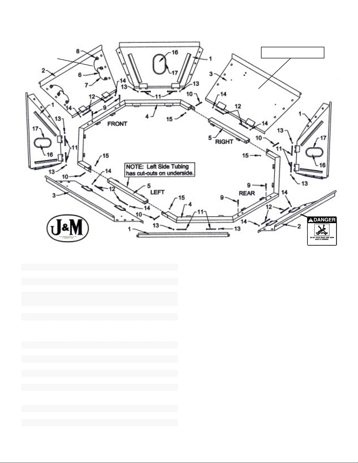
# Part # Description Qty
1 CIH-CP8010 Corner Panel 4
2 CIH-FRP8010 Front/Rear Panel 2
3 CIH-LRP8010 Left/Right Panel 2
4 CIH-FRF8010 Front/Rear Frame 2
5 CIH-TR8010L Tubing Rail (left w/cut-out) 1
5 CIH-TR8010R Tubing Rail (right) 1
6 CTE-PP Plastic Plug 8
7 CTE-PL Plastic Lanyard 24
8 CTE-LP Lynch Pin 24
9 HB-38212 8.8 x 2 1/4" Hex Bolt w/Heavy
Washer and Nut (opt.)
4
9 HBN-38212 3/8" x 2 1/2" Bolt w/ Flange Nut 4
10 HB-384 3/8" x 4" Bolt 8
11 HB-38412 3/8" x 4 1/2" Bolt 8
12 6MM-475 6MM Bolt x 4 3/4" (8.8) 8
13 LN-38 3/8" Lock Nut 8
14 6MM-NLN 6MM Nylon Lock Nut 8
15 FN-38 3/8" Flange Nut 10
16 IW-71212 Inspection Window 4
17 62095-7 Window Molding 4
18 PCS-316100 Panel Chain Support 1
19 FB-381 3/8" x 1 Flange Bolt 2
20 CTE-SS1 Step 1
21 34STS Self Tapping Screw 8
22 CIH-HR8010 Handrail 1
Lynch Pins shown
below are typical
on Front, Rear and
Side Panels
Combine Grain Tank Set-Up Instructions
for Case AFX 8010 Series Combines
Fold this Panel First
Assembly Instructions
Step One:
Remove 5/16” bolts in the combine cab that may interfere
with the placement of the grain tank framing members.
Place frame halves on combine hopper. Loosely fasten frame
halves combine hopper using one of the following options:
Option One: If combine has hex nuts welded to the top of
the combine at the front and rear frame members, simply
align the welded hex nuts with two of the cut-outs in the front
and rear frame and secure to the top of the combine using
four 8.8 x 2 1/4” hex bolt and heavy washer.
Option Two: If combine does not have hex nuts welded
to the top of the combine at the front and rear frame members,
align the front and rear frame members with the adjacent
holes in the top of the combine and secure using eight 3/8” x
2 1/2” Bolts and 3/8” Flange Nuts.
Step Two:
Fasten Tubing Rails (Note: Left side tubing rail has cut-outs
on the underside of the tube) to frame halves using four 3/8”
x 4” bolts with 3/8” lock nuts. Using self tapping screws,
secure the tubing rails (through the hinge hole) to the top of
the combine to prevent frame from lifting when panels are
folded.
Step Three:
Attach the corner panels to the hinges on the front and rear
frames as shown using eight 3/8” x 4 1/2” Bolts and 3/8”
Lock Nuts.
Page 2
Combine Grain Tank Set-Up Instructions (Continued)
for Case AFX 8010 Series Combines
Assembly Instructions (Continued)
Step Four:
Attach the front and side panels to the frame assembly as shown
using eight 1/4” x 4 1/2” bolts and 1/4” lock nuts. (Note: The panel
with the Danger Sticker should be installed as the rear panel.)
Step Five:
Push plastic plugs through plastic retainer lanyards and into existing
holes from inside extension. Fold end of lanyard around lynch pin
ring and snap into place.
Step Six:
Secure panels together by inserting and locking the lynch pin into
the adjacent tab weldment.
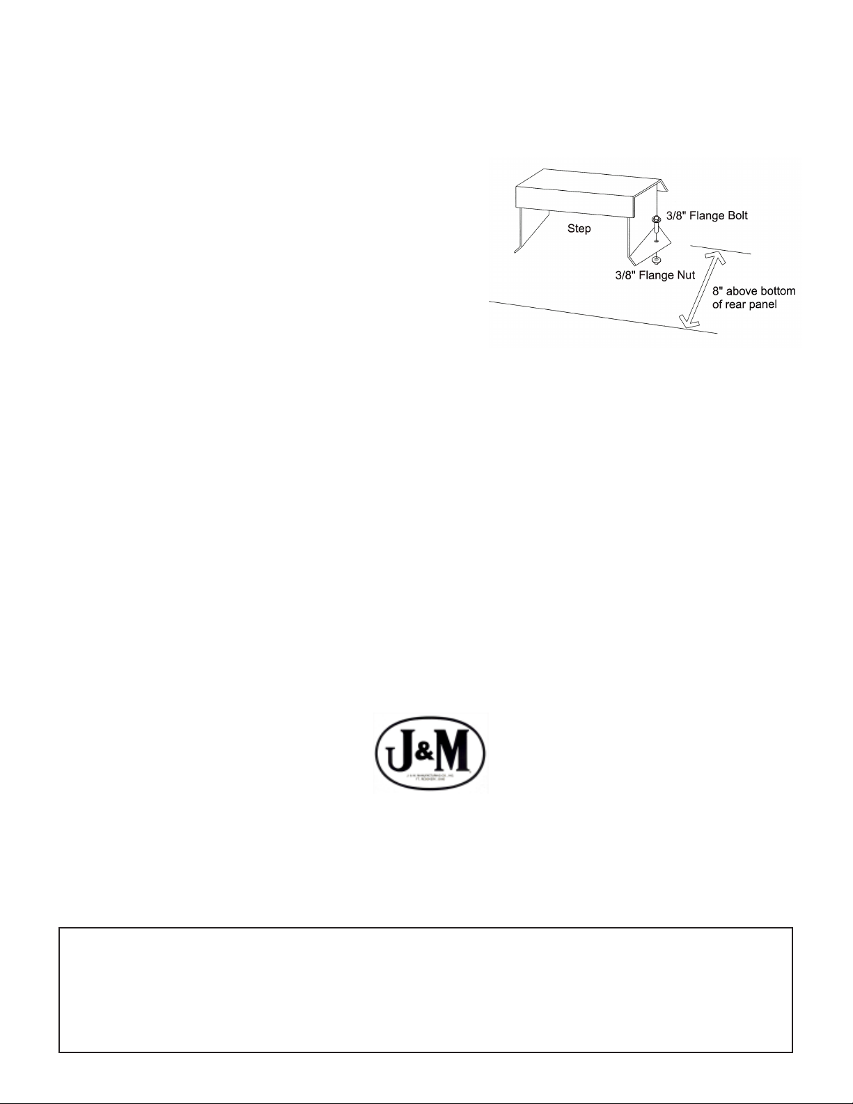
Step Seven:
On the grain tank extension rear panel, position the step
approximately 8” from the lower side of the panel and directly above
the step in the combine tank. Using the step as a template, mark
and drill two 13/32” holes in the rear panel. Attach the step using
two 3/8” x 1” flange bolts and 3/8” flange nuts. Note: Be sure the
step is positioned and mounted as shown.
Step Eight:
Install 3/16" x 100" Panel Support Chain from front to rear in
combine tank using bolts and nuts located in tank.
Folding the Panels
Step One:
Fold the side panels toward the middle of the
combine hopper.
Step Two:
Fold the front and rear panels inward.
Step Three:
Fold the four corner panels.
J. & M. Mfg. Co., Inc.
P.O. Box 547 Ft. Recovery, OH 45846
Ph: (419) 375-2376 Fax: (419) 375-2708
www.jm-inc.com
WARNING:
Use of this product is at the owner’s discretion. Increasing grain capacity may adversely affect center of gravity,
stability, and controllability. Exceeding maximum combine weight loadings can risk structural integrity and drive
line components. J. & M. Mfg. Co., Inc. does not assume any liabilities, or make any warranties regarding the
performance or structure of the combine. See combine owner’s/operator’s manual for specific limitations, operating
recommendations, and safety information.
 Loading...