


J. & M. Mfg. Co., Inc.
P.O. Box 547 Fort Recovery, OH 45846
Ph: (419) 375-2376 Fax: (419) 375-2708
www.jm-inc.com
(Rev. 7/8/13)

|
Table of Contents |
|
GENERAL INFORMATION |
|
|
|
|
1 |
To the dealer...................................................................................................................................................... |
1 |
|
|
|
1 |
Express warranty............................................................................................................................................... |
1 |
|
Service .............................................................................................................................................................. |
22 |
|
|
|
3 |
To the owner...................................................................................................................................................... |
3 |
|
|
|
3 |
Safety Ruler....................................................................................................................................................... |
3 |
|
1.0 OPERATIONS |
|
|
|
|
5 |
1.1 |
Preparing the Towing Vehicle..................................................................................................................... |
5 |
1.2 |
Preparing Speed Tender.............................................................................................................................. |
5 |
|
|
5 |
|
Hydraulics............................................................................................................................................ |
5 |
|
|
5 |
|
Lubrication........................................................................................................................................... |
5 |
|
|
5 |
|
Tires/Wheels........................................................................................................................................ |
5 |
1.3 |
Connection Speed Tender to Towing Vehicle............................................................................................. |
55 |
1.4 |
Transporting................................................................................................................................................ |
66 |
|
|
6 |
1.5 |
Hydraulic Power Unit Operations............................................................................................................... |
6 |
|
|
8 |
1.6 |
Field operation............................................................................................................................................. |
8 |
1.7 |
Filling Speed Tender from Another Wagon or Bulk Container ................................................................. |
10 |
1.8 |
Cleaning out Collapsible Hopper and Conveyor/Auger............................................................................. |
11 |
1.9 Adjusting the Tarp Tension in Hanger Bracket........................................................................................... |
13 |
|
1.10 Basic scale operation................................................................................................................................. |
1313 |
|
2.0 SERVICE |
|
|
2.1 |
Grease Conveyor/Auger Bearings............................................................................................................... |
1414 |
2.2 Grease Boom Arm....................................................................................................................................... |
1414 |
|
|
|
15 |
2.3 |
Tire pressure ............................................................................................................................................... |
15 |
2.4 |
Tightening Lugnuts ................................................................................................................................... |
15 |
2.5 |
Wheel bearings........................................................................................................................................... |
16 |
|
Bearing inspection and service............................................................................................................ |
16 |
|
Bearing cup replacements.................................................................................................................... |
16 |
2.6 |
Hydraulic Power Unit................................................................................................................................. |
17 |
|
Daily (every 5 hours of use)................................................................................................................. |
1717 |
|
|
17 |
|
Once per season (every 20-25 hours of use)........................................................................................ |
17 |
|
Every two to three years (every 78-80 hours of use)........................................................................... |
17 |
|
Replacing hydraulic parts.................................................................................................................... |
17 |
|
|
17 |
|
Purge air form system as follows......................................................................................................... |
17 |
2.7 |
Conveyor Belt Tracking.............................................................................................................................. |
17 |
|
Checking the belt tracking at collapsible hopper end.......................................................................... |
17 |
|
Checking the belt tracking at discharge end........................................................................................ |
17 |
2.8 Adjusting Conveyor Belt Tracking ............................................................................................................ |
18 |
|
2.9 |
Belt Tensioning .......................................................................................................................................... |
19 |
2.10 Electric Brakes.......................................................................................................................................... |
19 |
|
|
How to use your electric brakes properly............................................................................................ |
19 |
|
To synchronize ................................................................................................................................... |
19 |
|
How to adjust electric brakes............................................................................................................... |
2020 |
|
When to adjust brakes.......................................................................................................................... |
2020 |
|
Brake cleaning and inspection............................................................................................................. |
20 |
|
Brake shoe and lining inspection......................................................................................................... |
20 |
|
Replacing brake lining ...................................................................................................................... |
21 |
|
Brake lubrication................................................................................................................................. |
21 |
|
Troubleshooting................................................................................................................................... |
21 |
|
How to measure voltage...................................................................................................................... |
21 |
|
|
21 |
|
Brake magnet inspection...................................................................................................................... |
21 |
|
How to measure amperage................................................................................................................... |
2222 |
|
Replacing brake magnet....................................................................................................................... |
222 |
|
Brake drum inspection.......................................................................................................................... |
2323 |

|
|
|
|
|
|
Table of Contents |
|
2.11 Daily service (5-10 hours of use) ............................................................................................................ |
2323 |
||
2.12 |
End of the year service............................................................................................................................. |
2323 |
|
2.13 |
Removing from storage............................................................................................................................ |
2424 |
|
2.14 Troubleshooting ....................................................................................................................................... |
2525 |
||
2.15 |
Bolt torque specifications......................................................................................................................... |
2828 |
|
3.0 HYDRAULICS |
2929 |
||
3.1 |
Standard Models (Raise and lower boom only)......................................................................................... |
||
3.2 |
Deluxe Models (Raise and lower boom and open and close doors).......................................................... |
30 |
|
3.3 |
Deluxe Models with Conveyor/Auger Swing ............................................................................................ |
3131 |
|
4.0 WIRING |
3232 |
||
4.1 |
Hydraulic Wiring........................................................................................................................................ |
||
4.2 |
Light Wiring Harnesses.............................................................................................................................. |
3535 |
|
5.0 PARTS |
|
|
3939 |
5.1 |
Ladder Parts ............................................................................................................................................... |
||
5.2 |
Scale Parts .................................................................................................................................................. |
4040 |
|
5.3 |
Chassis Parts............................................................................................................................................... |
4141 |
|
5.4 A-Frame Parts ............................................................................................................................................ |
4242 |
||
5.5 Auger Parts ................................................................................................................................................ |
4343 |
||
5.6 |
Conveyor Parts ........................................................................................................................................... |
4545 |
|
5.7 Boom Arm Parts.......................................................................................................................................... |
4747 |
||
5.8 |
Hydraulic Door Parts ................................................................................................................................. |
4848 |
|
5.9 |
Manual Door Parts ..................................................................................................................................... |
4949 |
|
5.10 |
Drum Brake Parts (1)............................................................................................................................... |
50 |
|
5.11 Drum Brake Parts (2) .............................................................................................................................. |
51 |
||
5.12 |
Shell Parts ............................................................................................................................................... |
51 |
|
5.13 |
Roll Tarp Parts......................................................................................................................................... |
53 |
|
5.14 |
Spring Return Parts.................................................................................................................................. |
54 |
|
5.15 |
Boom Arm Hydraulic Swing Parts (optional).......................................................................................... |
5454 |
|
5.16 Available Options...................................................................................................................................... |
555 |
||
6.0 AFTERMARKET INSTALLATION INSTRUCTIONS |
5757 |
||
6.1 |
Scales Installation......................................................................................................................................... |
||

General Information
TO THE DEALER:
Read manual instructions and safety rules. Make sure all items on the Dealer’s Pre-Delivery and Delivery Check Lists in the Operator’s Manual are completed before releasing equipment to the owner.
The dealer must complete the Warranty Registration Card attached to the front inside cover of this manual and return to J. & M. Mfg. Co., Inc. at the address indicated on the card. Warranty claims will be denied if the Warranty Registration Card has not been completed and returned.
EXPRESS WARRANTY:
J. & M. Mfg. Co. Inc. warrants against defects in construction or materials for a period of ONE year. We reserve the right to inspect and decide whether material or construction was faulty or whether abuse or accident voids our guarantee.
Warranty service must be performed by a dealer or service center authorized by J. & M. Mfg. Co. Inc. to sell and/ or service the type of product involved, which will use only new or remanufactured parts or components furnished by J. & M. Mfg. Co. Inc. Warranty service will be performed without charge to the purchaser for parts or labor based on the Warranty Labor Times schedule. Under no circumstance will allowable labor times extend beyond the maximum hours indicated in the Warranty Labor Times schedule for each warranty procedure. The purchaser will be responsible, however, for any service call and/or transportation of the product to and from the dealer or service center’s place of business, for any premium charged for overtime labor requested by the purchaser, and for any service and/or maintenance not directly related to any defect covered under the warranty. Costs associated with equipment rental, product down time, or product disposal are not warrantable and will not be accepted under any circumstance.
Each warranty term begins on the date of product delivery to the purchaser. Under no circumstance will warranty be approved unless (i) the product warranty registration card (attached to the inside of the Operator’s Manual) has been properly completed and submitted to the equipment manufacturer, and (ii) a warranty authorization number has been issued by the equipment manufacturer. This Warranty is effective only if the warranty registration card is returned within 30 days of purchase.
This warranty does not cover a component which fails, malfunctions or is damaged as a result of (i) improper modification or repair, (ii) accident, abuse or improper use, (iii) improper or insufficient maintenance, or (iv) normal wear or tear. This warranty does not cover products that are previously owned and extends solely to the original purchaser of the product. Should the original purchaser sell or otherwise transfer this product to a third party, this Warranty does not transfer to the third party purchaser in any way. J. & M. Mfg. Co. Inc. makes no warranty, express or implied, with respect to tires or other parts or accessories not manufactured by J. & M. Mfg. Co. Inc. Warranties for these items, if any, are provided separately by their respective manufacturers.
THIS WARRANTY IS EXPRESSLY IN LIEU OF ALL OTHER WARRANTIES OR CONDITIONS, EXPRESS, IMPLIED OR STATUTORY, INCLUDING ANY IMPLIED WARRANTY OF MERCHANTABILITY OR FITNESS FOR PARTICULAR PURPOSE.
In no event shall J. & M. Mfg. Co. Inc. be liable for special, direct, incidental or consequential damages of any kind. The exclusive remedy under this Warranty shall be repair or replacement of the defective component at J. & M. Mfg. Co. Inc.’s option. This is the entire agreement between J. & M. Mfg. Co. Inc. and the Owner about warranty and no J. & M. Mfg. Co. Inc. employee or dealer is authorized to make any additional warranty on behalf of J. & M. Mfg. Co. Inc.
 1
1

General Information
The manufacturer reserves the right to make product design and material changes at any time without notice. They shall not incur any obligation or liability to incorporate such changes and improvements in products previously sold to any customer, nor shall they be obligated or liable for the replacement of previously sold products with products or parts incorporating such changes.
SERVICE:
The equipment you have purchased has been carefully manufactured to provide dependable and satisfactory use.
Like all mechanical products, it will require cleaning and upkeep. Lubricate the unit as specified. Observe all safety information in this manual and safety signs on the equipment.
For service, your authorized J. & M. dealer has trained mechanics, genuine J. & M. service parts, and the necessary tools and equipment to handle all your needs.
Use only genuine J. & M. service parts. Substitute parts may void the warranty and may not meet standard required for safe and satisfactory operating. Record the model number and serial number of your equipment in the spaces provided:
Serial #_______________ Purchase Date: _______________ Purchased From: ____________________
Please provide this information to your dealer to obtain the correct parts:
 2
2

General Information
TO THE OWNER:
The purpose of this manual is to assist you in operating and maintaining your Speed Tender in a safe manner. Read it carefully. It furnishes information and instructions that will help you achieve years of dependable performance and help maintain safe operating conditions. If this machine is used by an employee or is loaned or rented, make certain that the operator(s), prior to operating:
1.Is instructed in safe and proper use.
2.Review and understands the manual(s) pertaining to this machine.
Throughout this manual, the term IMPORTANT is used to indicate that failure to observe can cause damage to equipment. The terms CAUTION, WARNING and DANGER are used in conjunction with the Safety-Alert Symbol. When you see this symbol, carefully read the message that follows and be alert to the possibility of personal injury or death.
This Safety-Alert symbol indicates a hazard and means ATTENTION! BECOME ALERT! YOUR SAFETY IS INVOLVED!
 DANGER: Indicates an imminently hazardous situation that, if not avoided, will result in death or serious injury.
WARNING: Indicates a potentially hazardous situation that, if not avoided, could result in death or serious injury, and includes hazards that are exposed when guards are removed.
 CAUTION: Indicates a potentially hazardous situation that, if not avoided, may result in minor or moderate injury.
IMPORTANT: Indicates that failure to observe can cause damage to equipment.
NOTE: Indicates helpful information.
SAFETY RULES:
 ATTENTION! BECOME ALERT! YOUR SAFETY IS INVOLVED!
Safety is a primary concern in the design and manufacture of our products. Unfortunately, our efforts to provide safe equipment can be erased by an operator’s single careless act. In addition, hazard control and accident prevention are dependent upon the awareness, concern, judgment, and proper training of personnel involved in the operation, transport, maintenance and storage of equipment.
Make certain that the operator(s), prior to operating is instructed in safe and proper use and reviews and understands the manual(s) pertaining to this machine. Also make certain that the operator(s) reviews and understands the operator’s manual of the tow vehicle prior to hooking up or operating the Speed Tender.
Read this manual before you operate this machine. If you do not understand any part of this manual, or need more information, contact the manufacturer or your authorized dealer.
Safety Rules Next Page
 3
3

General Information
1.Understand that your safety and the safety of other persons are measured by how you service and operate this machine. Know the positions and functions of all controls before you try to operate them. Make sure to check all controls in a safe area before starting your work.
2.The safety information given in this manual does not replace safety codes, federal, state, or local laws. Make certain your machine has the proper equipment as designated by local laws and regulations.
3.A frequent cause of personal injury or death is from persons falling off equipment and being run over. Do not permit persons to ride on this machine.
4.Secure Speed Tender safety chain to towing vehicle before transporting. Do not transport without safety chains being attached to tow vehicle.
5.Make sure that the conveyor/auger is fastened securely to the boom arm, and the boom arm is resting on the boom arm support with lynch pin in place before transport.
6.Use good judgment when transporting Speed Tender on a highway. Maintain complete control at all times. Regulate speed to road conditions. Do not transport unit with rear compartment full and front compartment empty. The unit may not be properly balanced, offsetting the tongue weight of the Speed Tender.
7.When transporting on public roads, the conveyor must be in the forward position to meet with lighting and visibility marking requirements.
8.Do not travel faster than 10 m/h. during off highway travel. Drive slowly over rough ground, hill sides, and around curves to avoid tipping. Use extreme care when operating close to ditches, fences, or on hill sides.
9.Use care when moving or operating Speed Tender near electric lines as serious injury or death can result from contact.
10.Never adjust, service, clean, or lubricate Speed Tender until all power is shut off and the battery is disconnected. Keep all safety shields in place.
11.Carbon monoxide can cause severe nausea, fainting, or death. Do not operate engine in closed or confined work area.
12.Explosive fuel can cause fires and severe burns. Stop engine before filling fuel tank.
13.Hot parts can cause severe burns. Do not touch engine while operating or just after stopping.
14.Hydraulic oil leaking under pressure can penetrate skin and cause infection or other injury.
15.To prevent personal injury when working with hydraulic power unit:
a.Relieve all pressure before disconnecting fluid lines.
b.Before applying pressure, make sure all connections are tight and components are in good condition.
c.Never use your hand to check for suspected leaks under pressure. Use a piece of cardboard or wood for this purpose.
16.Make sure that everyone is clear of equipment before applying power or moving the Speed Tender.
17.Before filling the Speed Tender, make certain that no one is inside the grain tanks. Never allow children or anyone in, near, or on the Speed Tender during transport or during loading and unloading of grain. Be aware that moving grain is dangerous and can cause entrapment, resulting in severe injury or death
by suffocation.
18.Before unhooking the Speed Tender from the transport vehicle, be sure to properly block the wheels to prevent the Speed Tender from moving.
19.When using the Conveyor Swing option be sure to stand clear of the swining boom arm at all times.
 4
4

1.0 Operations
1.1 Preparing the Towing Vehicle
Before towing the Speed Tender, refer to towing vehicle’s owner’s manual for information concerning hitch capacities, hitch adjustments, and tire inflation.
Towing vehicle must be equipped with proper electric braking components.
NOTE: The Speed Tender is equipped with LED lights. The towing vehicle may require a flasher upgrade for lights to operate properly.
Do not exceed towing vehicles GVWR (Gross Vehicle Weight Rating) or GCWR (Gross Combination Weight Rating), or the maximum hitch load.
1.2 Preparing Speed Tender
Hydraulics: Check routing of all hydraulic hoses. Hoses should not be kinked, twisted or rubbing against sharp edges. Check all hoses and fittings for hydraulic leaks. Tighten and /or repair or replace as required.
Lubrication: Lubricate Speed Tender as outlined in Service section 2.1. Refer to engine manual for proper fluid levels in engine.
Tires/Wheels: Check tire pressures and maintain at recommended operating pressure. It is important to check wheel nut/bolts for proper torque as recommended. You can find proper tire pressure and wheel torque located in service manual section.
1.3 Connecting Speed Tender to the Towing Vehicle
 WARNING: Do not stand between the Speed Tender and tow vehicle when hooking up.
NOTE: The Speed Tender comes standard with a 2 5/16” ball coupler and has an optional
3” lunette eye. Also the Speed Tender can come with an optional Gooseneck Frame in place of the A-Frame. The Gooseneck Frame can feature either a 2 5/16” ball coupler or a 5th Wheel hook up.
1.Back tow vehicle up to Speed Tender.
2.Align the vehicle’s ball or lunette eye with the coupler or ring on the Speed Tender.
3.Lift tongue latch lever.
4.Lower jack to set Speed Tender coupler down on ball or lunette eye hook.
5.Latch coupler and insert pin. Check to make sure that coupler is securely latched.
6.Pivot jack to transport position and pin in place.
7.Attach 7-way plug to tow vehicle. Check the length of the Speed Tender 7-way to make sure that it is long enough to turn, but not too long to touch the ground.
NOTE: Check to make sure that lights are in proper operating condition and repair or replace if necessary.
8.Connect the brake breakaway cable to towing vehicle.
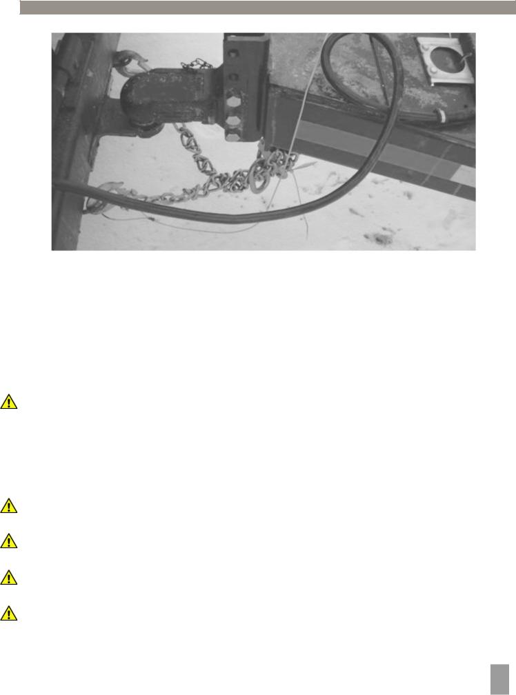
9.Attach safety chains to tow vehicle by crossing chains (Figure 1.1). Allow enough slack in chains necessary for turning.
10.Test the breaks and all the lights on the Speed Tender
WARNING: Check safety chains for broken, stretched or damaged link or end fittings.
Replace chains if found to be damaged. Do not weld safety chains.
 5
5
1.0 Operations
Figure 1.1
1.4 Transporting
NOTE: Make sure the jack is in the horizontal position before transporting.
NOTE: Check to make sure the boom arm is in the boom rest and the lynch pin is in place with the conveyor/auger ratchet strap securely fastened.
NOTE: Make sure that the collapsible hopper is in the up position.
When transporting the Speed Tender on public roads, it is recommended to have the boom in the forward facing position. The rearward facing position may not comply with state law for lighting and marking requirements.
WARNING: Travel at a safe speed that allows you to maintain complete control of towing vehicle and Speed Tender at all times.
1.5 Hydraulic Power Unit Operation
 WARNING: Explosive fuel can cause fires and severe burns. Stop engine before filling fuel tank.
WARNING: Carbon monoxide can cause severe nausea, fainting or death. Do not operate engine in an enclosed or confined area.
WARNING: Hot parts can cause severe burns. Do not touch engine while operating or just after stopping.
WARNING: Acid from battery can cause fires and severe acid burns. Make sure to charge battery in well-ventilated area.
WARNING: Make sure to relieve hydraulic pressure before working on hydraulic system.
 6
6
1.0 Operations
WARNING: Purge hydraulic system of air before operating Speed Tender to prevent serious injury or death.
WARNING: Wear proper hand and eye protection when searching for leaks. Use wood or cardboard instead of hands.
1.Check to make sure all fittings and hardware are in proper operating condition. Replace if worn or broken. Check engine fluid levels and sight gauge on reservoir for proper operating levels.
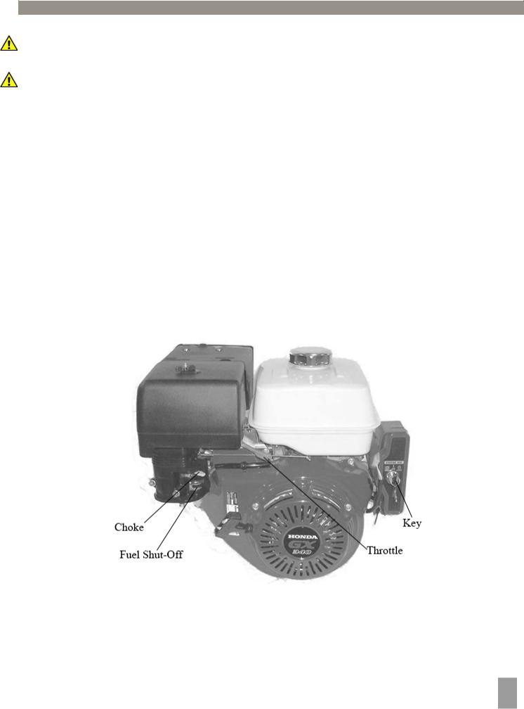
2.Slide the Fuel Shut-off Lever to the “ON” position (Figure 1.2).
3.Slide Choke Lever to the “ON” position (Figure 1.2).
4.Turn the key to the start position. Once engine starts, release key (Figure 1.2).
5.After starting, allow the engine to warm-up. Slide choke to the “OFF” position, and increase throttle speed (Figure 1.2).
6.To turn the engine off, slide the Fuel Shut-off to the “OFF” position (Figure 1.2).
NOTE: In extremely cold weather, it is best to allow engine and hydraulics to warm-up before increasing throttle speed.
NOTE: If a hydraulic leak appears, turn off immediately and take appropriate action. NOTE: See Engine manual for more details on upkeep and service.
Figure 1.2
 7
7
1.0 Operations
1.6 Field Operation
WARNING: The Speed Tender must be hooked to the towing vehicle during loading and unloading.
1.Position the Speed Tender next to the planter/drill so the conveyor/auger will reach the planter box.
2.Remove lynch pin from Boom Arm. (Figure 1.3).
3.Start the hydraulic power unit and increase throttle speed. (Allow hydraulic fluid to warm-up.)
(Figure 1.2).
4.Raise the boom out of the Boom Rest using the handheld control (Figure 1.4).
NOTE: Wireless options feature a Wireless Remote (Figure 1.4).
5.Move the Boom Lock Handle to the unlock position. This will allow the boom to swing side to side (Figure 1.3).
NOTE: Hydraulic swing for the Conveyer/Auger is available.
WARNING: When operating the hydraulic swing option, Do Not stand in the operating range of the Conveyer/Auger.
Operating Range
WARNING: If you are parked on an incline the boom arm may swing freely. (It is advised that you do not use the Speed Tender on uneven ground).
6.When conveyor/auger is located in desired position slide the boom lock handle to the lock position.
7.Check to make sure the hopper is in the up position (Figure 1.4)
Figure 1.3
 8
8

1.0 Operations
Wireless |
Handheld |
Manual |
|
Hand Wheels |
|||
Remote |
Control |
||
|
Figure 1.4 |
Figure 1.5 |
See Section 4.1 for Remote Options |
|
Hopper Up |
|
Figure 1.6
8.Open door on Speed Tender with manual hand wheel (Figure 1.5).
NOTE: The deluxe option handheld control and wireless remote operates the opening and closing of hydraulic doors (Figure 1.4).
WARNING: Empty-out the rear compartment first to help prevent the chance of flipping the
Speed Tender.
9.Use the Handheld Control or Wireless Remote to start the conveyor/auger.
10.Fill the planter/drill to desired level then repeat.
NOTE: Adjusting engine throttle will regulate conveyor/auger speed.
11.Close door on Speed Tender before the last planter seed box is full so you can completely empty-out collapsible hopper and conveyor/auger.
12.Move the boom lock handle to the unlock position (Figure 1.3).
CAUTION: If you are parked on an incline the boom arm may swing freely. (It is advised that you do not use the Speed Tender on uneven ground).
 9
9

1.0Operations
13.Position boom above boom rest and lower to allow its full weight on the boom rest.
14.Replace lynch pin in Boom Arm.
15.Move the boom locking handle to lock position.
16.Make sure that the conveyor/auger hold down ratchet strap is tight enough that the conveyor auger will not move during transportation.
17.Make sure the collapsible hopper is in the up position for storage (Figure 1.6).
NOTE: If you are not using an optional hopper cover this will help the water drain out of the hopper.
18.Run the engine at 1/2 to full rpm for 20 minutes to recharge the battery.
19.Slide the fuel shut off lever to the “OFF” position. This will allow the engine to shutoff by running out of gas.
20.Turn the key to the “OFF” position.
1.7 Filling Speed Tender From Another Wagon or Bulk Container
WARNING: The Speed Tender must be hooked to the towing vehicle during loading and unloading.
1.Remove lynch pin from Boom Arm (Figure 1.3).
2.Start the hydraulic power unit and increase throttle speed. (Allow hydraulic fluid to warm up.)
NOTE: Make sure collapsible hopper is in the down position.
3.Raise the boom out of boom rest using the handheld control. (Figure 1.4).
NOTE: Wireless options feature a Wireless Remote (Figure 1.4).
4.Move the boom lock handle to the unlock position. This will allow the boom to swing (Figure 1.3).
CAUTION: If you are parked on an incline, the boom arm may swing freely. (It is advised that you do not use Speed Tender on uneven ground)
5.Rotate the conveyor/auger to 45 deg. (Figure 1.8)
6.Lower the boom so you can remove the telescoping spout from the discharge end of the conveyor/auger.
7.Undo the conveyor/auger hold down ratchet strap (Figure 1.3).
8.Swing the collapsible hopper end out from under the Speed Tender shell.
9.Position the discharge end over the Speed Tender.
NOTE: The conveyor/auger is equipped with a stand (Figure 1.7). (It is recommended for use whenever possible to maximize conveyor performance and for easier access to discharge point on bulk seed containers).
10. Lock the Boom Arm in place. |
45 deg. |
|
Conveyer/Auger
Stand
Figure 1.7 |
Figure 1.8 |
 10
10

1.0Operations
11.Lock collapsible hopper in the up position (Figure 1.6).
12.Position the wagon or bulk seed container over the collapsible hopper.
13.Use the handheld controller or wireless remote to start the conveyor/auger.
14.Fill the Speed Tender to desired level.
 WARNING: Fill the front compartment first to help prevent the chance of flipping.
15.Run the conveyor/auger until the collapsible hopper is empty.
16.When finished loading seed into the Speed Tender, move the wagon or bulk seed container away from conveyor/auger.
17.Place collapsible hopper in the down position.
18.With the Boom Arm at a 45 deg. angle and locked, Swing the conveyor/auger back into the resting position on the boom arm (Figure 1.8).
19.Place the conveyor/auger hold down ratchet strap around the conveyor/auger and tighten the strap (Figure 1.3).
20.Move the boom locking handle to the unlock position (Figure 1.3).
CAUTION: If you are parked on an incline, the boom arm may swing freely. (It is advised that you do not use the Speed Tender on uneven ground.)
21.Position boom arm above the boom rest and lower to allow its full weight on the boom rest.
22.Replace lynch pin in boom arm pin.
23.Move the boom lock handle to the lock position.
24.Make sure that the conveyor/auger hold down ratchet strap is tight enough that the conveyor/auger will not move during transport.
25.Make sure the collapsible hopper is in the up position for storage (Figure 1.6).
NOTE: This will help the water drain out of the hopper.
26.Run the engine at 1/2 to full rpm for 20 minutes to recharge the battery.
27.Slide the fuel shut off lever to the “OFF” position. This will allow the engine to shutoff by running out of gas.
28.Turn the key to the “OFF” position.
1.8 Cleaning out Collapsible Hopper and Conveyer/Auger
WARNING: The Speed Tender must be hooked to the towing vehicle during loading and unloading.
1.Remove lynch pin from Boom Arm (Figure 1.3).
2.Start the hydraulic power unit and increase throttle speed. (Allow hydraulic fluid to warm up if it is cold outside) (Figure 1.2).
NOTE: Make sure collapsible hopper is in the down position.
3.Raise the boom out of boom rest using the handheld control. (Figure 1.4).
NOTE: Wireless options feature a Wireless Remote (Figure 1.4).
4.Move the boom lock handle to the unlock position. This will allow the boom to swing (Figure 1.3).
CAUTION: If you are parked on an incline, the boom arm may swing freely. (It is advised that you do not use Speed Tender on uneven ground).
5.Rotate the conveyor/auger to 45 deg. (Figure 1.8).
6.Lower the boom so you can remove the telescoping spout from the discharge end of the conveyor/auger.
 11
11

1.0Operations
7.Undo the conveyor/auger hold down ratchet strap (Figure 1.3).
8.Swing the collapsible hopper end out from under the Speed Tender shell.
9.Move the boom lock handle to the “Lock” position.
10.Place the collapsible hopper in the up position (Figure 1.6)
11.With the discharge end lower than the collapsible hopper end, place the discharge end into a 5 Gal. bucket (Figure 1.9). Using the hand held controller, start the conveyor/auger and run until completely empty.
12.Lower the collapsible hopper end back down to the ground. This will allow you to open the clean-out door. (Figure 1.10)
Auger Clean-
out Coor
Conveyer Clean-
out Door
Figure 1.9 |
Figure 1.10 |
13.Place collapsible hopper in the down position.
14.Move the boom lock handle to the unlock position (Figure 1.3).
CAUTION: If you are parked on an incline, the boom arm may swing freely. (It is advised that you do not use Speed Tender on uneven ground).
15.With the boom arm at a 45 Deg. angle, Swing the conveyor/auger back into the resting position on the boom arm (Figure 1.8).
16.Place the conveyor/auger hold down ratchet strap around the conveyor/auger and tighten the strap (Figure 1.3).
17.Position boom arm above boom rest and lower to allow its full weight on the boom rest.
18.Replace lynch pin in boom pin.
19.Move the boom lock handle to the lock position.
20.Make sure that the conveyor/auger hold down ratchet strap is tight enough that the conveyor/auger will not move during transportation.
21.Make sure the collapsible hopper is in the up position for storage (Figure 1.6).
NOTE: This will help the water drain out of the hopper.
22.Slide the fuel shut off lever to the “OFF” position. This will allow the engine to shutoff by running out of gas.
23.Turn the key to the “OFF” position.
 12
12

1.0 Operations
1.9 Adjusting the Tarp Tension in Hanger Bracket
1.Fully unroll the tarp as shown in Figure 1.11.
2.Remove the two bolts that hold the tarp U-Joint on the splined shaft.
3.Remove the u-joint from the spline shaft.
4.Rotate u-joint and handle three or four spline teeth.
NOTE: Clockwise to tighten the tarp or counter-clockwise to loosen it.
5.Slide the u-joint and handle back onto the spline shaft.
6.Replace and tighten the two bolts.
U-Joint
 Bolts
Bolts
Figure 1.11
1.10 Basic Scale Operations
1.Turn the scale “ON” by pressing the on/off button. The display shows “Hello” then the current weight value is displayed.
2.Press G/N to access the gross mode. (Live scale weight is displayed in the G/N weighing mode.)
3.In the gross mode, press the ZERO/CLEAR key to zero the indicator when the Speed Tender is empty.
4.After initial amount is placed on the scale, press the TARE Key. (Weight is tarred off and goes into net mode, showing weight).
5.Load or unload material as needed (Shows + when loading and a – value when unloading).
6.When the display reaches the proper amount, stop loading or unloading.
7.Repeat steps 2 through 4 until complete.
NOTE: For more information, refer to the scale manual.
 13
13

2.0 Service
2.1 Grease Conveyer/Auger Bearings
Grease the conveyor/auger bearings every 10 hours of operation and before storage. Use only two pumps of grease per bearing (Figure 2.1).
NOTE: Over lubrication of these bearings will result in premature failure.
NOTE: The conveyor has four bearings that need grease (two at each end). The auger is equipped with one bearing (at hopper end).
Grease Point
Figure 2.1
2.2 Grease Boom Arm
Grease pivot points on boom arm every 50 hours and before storage (Figure 2.2).
Grease Points
Figure 2.2
 14
14

2.0 Service
2.3 Tire Pressure
The following is to be used as a general guide for tire inflation. Figures can vary depending on specific brand of tire used. It is important that tires are inspected before and after unit is loaded. Start with the minimum pressure indicated. The tire should stand up with no side wall buckling or distress as tire rolls. Do not exceed maximum recommended tire pressure. 80 psi is the cold rating on the tire that is standard for the Speed Tender. J&M also recommends to rotate your tires front to back (not side to side) every 1,200 miles or 12 months (whichever comes first) for longer tire life. Firgure 2.3 below is a troubleshooting chart used to ensure the tires wear evenly.
Figure 2.3
2.4 Tightening Lugnuts
Torque lug-nuts on new and removed wheels to 220 ft. lbs. after the first 10, 25, and 50 miles of driving, then recheck torque every 50 hours or every year, whichever comes first.
 15
15

2.0 Service
2.5 Wheel Bearings
The wheel bearings need to be cleaned, inspected, and repacked every 12 months or 12,000 miles. Use a number 2 wheel bearing grease to repack the bearings.
Bearing Inspection and Service:
1.Jack up Speed Tender.
2.Remove wheel lug-nuts.
3.Remove wheel from hub.
4.Remove grease cap.
NOTE: Be careful not to dent or cut a hole in grease cap.
5.Remove the cotter pin, nut, and washer.
6.Wiggle the hub to take the outer wheel bearing out.
7.Pull hub assembly straight off the axle. If you want to reuse the grease seal, (which is not recommended), be careful to support the weight of the hub so that the end of the axle does not ruin the rubber part of the grease seal.
8.To remove the inner bearing, you must remove the grease seal.
9.Remove inner bearing.
10.Wash all grease and oil from the bearing cone using a suitable solvent. Dry the bearing with a clean, lintfree cloth and inspect each roller completely. If any pitting, scalding, or corrosion is present, then
the bearing must be replaced. The bearing cups inside the hub must be inspected.
NOTE: Bearings must always be replaced in sets of a cone and a cup (See bearing cup replacement on following page.)
11.Repack inner bearing with new grease.
A.Place a moderate amount of grease in the palm of one hand.
B.Hold the inner bearing, large side down, in your other hand
C.Using the edge of the bearing like an ice-cream scoop, work it in until you see fresh grease come out of the top side of the bearing.
D.Rotate 1/8 of a turn and repeat until the whole bearing is full of fresh grease.
12.Place the inner bearing in the back of the wheel hub and add a liberal dose of grease.
13.Position the new wheel seal in its recess and lightly set it with a hammer.
NOTE: Be careful to not deform the metal part of the seal.
14.Slide the hub assembly onto the spindle and push it back into position.
15.Grease the outer bearings by hand. (See step 11)
16.Slide it and the spindle washer onto the spindle and into the hub recess.
17.Install and bottom out the spindle nut, then back it off 1/4 turn.
18.Reinstall the spindle nut and replace the cotter pin with a new one.
NOTE: If the castle nut does not line up with the hole in the spindle, then loosen the nut slightly until it does.
19.Pack the bearing cap with fresh grease and lightly drive it into the hub recess with a hammer.
20.Reinstall the wheel onto the hub and torque the wheel lug-nuts.
NOTE: See wheel nut/bolt torque requirements located in section 2.4.
Bearing cup replacement:
1.Place the hub on a flat work surface with the cup to be replaced on the bottom side.
2.Using a brass drift punch, carefully tap around the small diameter end of the cup to drive it out.
3.After cleaning the hub bore area, replace the cup by tapping it with the brass drift punch. Be sure the cup is seated all the way up against the retaining shoulder in the hub.
 16
16
 Loading...