

Page 1
Lanyards and
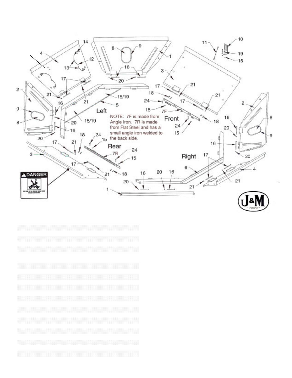
# Part # Description Qty
1 CIH-CP1 Corner Panel 2
2 CIH-CP2 Corner Panel 2
3 CIH-FRP Front/Rear Panel 2
4 CIH-LRP Left/Right Panel 2
5 CIH-LF Left Frame 1
6 CIH-RF Right Frame 1
7F CIH-AR-F Angle Iron Rail 1
7R CIH-AR-R Flat Rail (with welded angle iron) 1
8 IW-71212 Inspection W indow 4
9 62095-7 Window Molding 4
10 CIH-SMB Sensor Mounting Bracket 1
11 CIH-EW1 Extension Wire 1
12 CTE-PP Plastic Plug 8
13 CTE-PL Plastic Lanyard 16
14 CTE-LP Lynch Pin 16
15 FN-516 5/16" Flange Nut 8
16 HB-38412 3/8" x 4 1/2" Bolt 8
17 6MM-475 6MM Bolt x 4 3/4" (8.8) 8
18 FB-381 3/8" x 1" Flange Bolt 10
19 FB-51658 5/16" x 5/8" Flange Bolt 4
20 LN-38 3/8" Lock Nut 8
21 6MM-NLN 6MM Nylon Lock Nut 8
22 FN-38 3/8" Flange Nut 2
23 CTE-SS1 Step 1
24 FB-516112 5/16" x 1 1/2" Flange Bolt 4
Lynch Pins
shown below
are typical on
Front, Rear
and Side
Panels
Combine Grain Tank Set-Up Instructions
for Case IH 1660, 1666, 2166, 2366, 1680, 1688, 2188 & 2388 Series Combines
Assembly Instructions
Step 1:
Lay out the frame halves, Angle Iron Rail and Flat Rail on the
top of the combine as shown. Attach Angle Iron and Flat Rails
to frame halves using eight 3/8” x 1” Flange Bolts. (NOTE:
The Flat Rail has a small angle iron welded to the rear side.)
Step 2:
Drill holes to secure to combine tank using four 5/16” x 1 1/2”
Flange Bolts and four 5/16” Flange Nuts.
Step 3:
Drill Holes and fasten Left Frame Plate to combine using two
5/16” x 5/8” Flange Bolts and two 5/16” Flange Nuts.
Step 4:
Layout corner panels as shown and attach using eight 3/8” x
4 1/2” Bolts and eight 3/8” Lock Nuts.
Step 5:
Attach side panels to frame using four 1/4” x 4 1/2” Bolts and
four 1/4” Lock Nuts
Step 6:
Attach front and rear panels to frame using four 1/4” x 4 1/2”
Bolts and four 1/4” Lock Nuts. NOTE: The panel with the
Danger Decal should be used as the rear panel.
Page 2

Combine Grain Tank Set-Up Instructions
for Case IH 1660, 1666, 2166, 2366, 1680, 1688, 2188 & 2388 Series Combines
Assembly Instructions (Continued)
Step 7:
Push plastic plugs through retainer lanyards and into existing holes from inside extension. Fold end of lanyard around
lynch pin ring and snap into place.
Step 8:
Remove existing sensor from current position. Drill holes and install Sensor Mounting Bracket in center of front panel using
two 5/16” x 5/8” Flange Bolts and two 5/16” Flange Nuts. Bolt sensor to Sensor Mounting Bracket and reconnect.
Step 9:
On the grain tank extension rear panel, position the step
approximately 8” from the lower side of the panel and directly above
the step in the combine tank. Using the step as a template, mark
and drill two 13/32” holes in the rear panel. Attach the step using
(2) 3/8” x 1” Flange Bolts and Flange Nuts. NOTE: Be sure the
step is positioned and mounted as shown.
Folding the Panels
Step One:
Fold the side panels toward the middle of the
combine hopper.
Step Two:
Fold the front and rear panels inward.
Step Three:
Fold the four corner panels.
Ph: (419) 375-2376 Fax: (419) 375-2708
J. & M. Mfg. Co., Inc.
P.O. Box 547 Ft. Recovery, OH 45846
www.jm-inc.com
WARNING:
Use of this product is at the owner’s discretion. Increasing grain capacity may adversely affect center of gravity,
stability, and controllability. Exceeding maximum combine weight loadings can risk structural integrity and drive
line components. J. & M. Mfg. Co., Inc. does not assume any liabilities, or make any warranties regarding the
performance or structure of the combine. See combine owner’s/operator’s manual for specific limitations, operating
recommendations, and safety information.
 Loading...