

Page 1
OPERATOR’S MANUAL
and Set-Up Instructions for
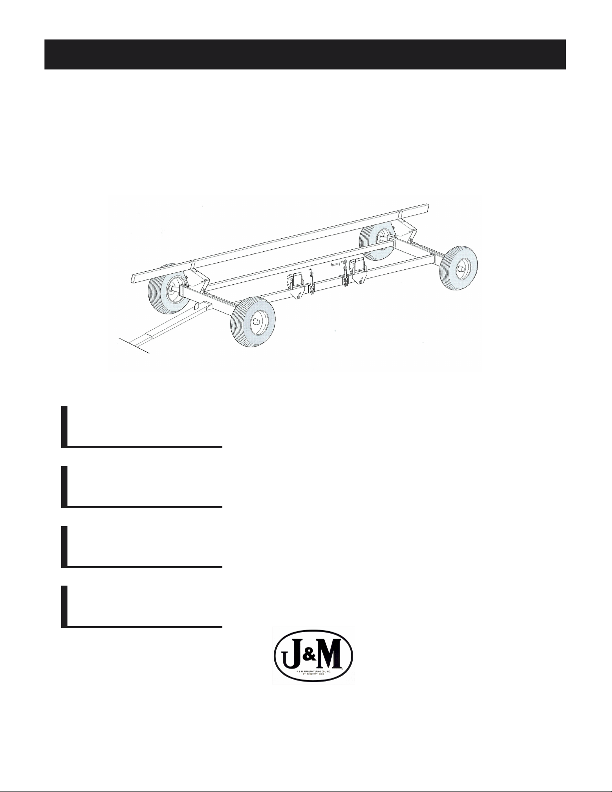
HEADER TRANSPORTS
HT-874
HT-874L
HT-874XL
HT-874XL-36
JMMAN0101 (Rev . 08/01/05)
J. & M. Mfg. Co., Inc.
P.O. Box 547 Ft. Recovery, OH 45846
Ph: (419) 375-2376 Fax: (419) 375-2708
www.jm-inc.com
Page 2

TO THE DEALER:
Read manual instructions and safety rules. Make sure all items on the Dealer’s Pre-Delivery and Delivery Check Lists
in the Operator’s Manual are completed before releasing equipment to the owner.
The dealer must complete the Warranty Registration Card attached to the front inside cover of this manual and return
to J. & M. Mfg. Co., Inc. at the address indicated on the card. Warranty claims will be denied if the Warranty
Registration Card has not been completed and returned.
EXPRESS WARRANTY :
J. & M. Mfg. Co. Inc. warrants against defects in construction or materials for a period of ONE year . We reserve the right
to inspect and decide whether material or construction was faulty or whether abuse or accident voids our guarantee.
Warranty service must be performed by a dealer or service center authorized by J. & M. Mfg. Co. Inc. to sell and/or
service the type of product involved, which will use only new or remanufactured parts or components furnished by J.
& M. Mfg. Co. Inc. Warranty service will be performed without charge to the purchaser for parts or labor based on the
Warranty Labor Times schedule. Under no circumstance will allowable labor times extend beyond the maximum
hours indicated in the Warranty Labor Times schedule for each warranty procedure. The purchaser will be responsible,
however, for any service call and/or transportation of the product to and from the dealer or service center ’s place of
business, for any premium charged for overtime labor requested by the purchaser, and for any service and/or
maintenance not directly related to any defect covered under the warranty. Costs associated with equipment rental,
product down time, or product disposal are not warrantable and will not be accepted under any circumstance.
Each warranty term begins on the date of product delivery to the purchaser. Under no circumstance will warranty be
approved unless (i) the product warranty registration card (attached to the inside of the Operator’s Manual) has been
properly completed and submitted to the equipment manufacturer, and (ii) a warranty authorization number has been
issued by the equipment manufacturer. This Warranty is effective only if the warranty registration card is returned
within 30 days of purchase.
This warranty does not cover a component which fails, malfunctions or is damaged as a result of (i) improper
modification or repair, (ii) accident, abuse or improper use, (iii) improper or insufficient maintenance, or (iv) normal
wear or tear. This warranty does not cover products that are previously owned and extends solely to the original
purchaser of the product. Should the original purchaser sell or otherwise transfer this product to a third party, this
Warranty does not transfer to the third party purchaser in any way. J. & M. Mfg. Co. Inc. makes no warranty , express or
implied, with respect to tires or other parts or accessories not manufactured by J. & M. Mfg. Co. Inc. Warranties for
these items, if any, are provided separately by their respective manufacturers.
THIS WARRANTY IS EXPRESSL Y IN LIEU OF ALL OTHER W ARRANTIES OR CONDITIONS, EXPRESS, IMPLIED OR
STATUTORY, INCLUDING ANY IMPLIED WARRANTY OF MERCHANTABILITY OR FITNESS FOR PARTICULAR
PURPOSE.
In no event shall J. & M. Mfg. Co. Inc. be liable for special, direct, incidental or consequential damages of any kind. The
exclusive remedy under this Warranty shall be repair or replacement of the defective component at J. & M. Mfg. Co.
Inc’s. option. This is the entire agreement between J. & M. Mfg. Co. Inc. and the Owner about warranty and no J. & M.
Mfg. Co. Inc. employee or dealer is authorized to make any additional warranty on behalf of J. & M. Mfg. Co. Inc.
The manufacturer reserves the right to make product design and material changes at any time without notice. They
shall not incur any obligation or liability to incorporate such changes and improvements in products previously sold to
any customer, nor shall they be obligated or liable for the replacement of previously sold products with products or
parts incorporating such changes.
SERVICE:
The equipment you have purchased has been carefully manufactured to provide dependable and satisfactory use.
Like all mechanical products, it will require cleaning and upkeep. Lubricate the unit as specified. Observe all safety
information in this manual and safety signs on the equipment.
For service, your authorized J. & M. dealer has trained mechanics, genuine J. & M. service parts, and the necessary
tools and equipment to handle all your needs.
Use only genuine J. & M. service parts. Substitute parts may void the warranty and may not meet standards required
for safe and satisfactory operation. Record the model number and serial number of your equipment in the spaces
provided:
Serial No.: Date of Purchase:
Purchased From:
Provide this information to your dealer to obtain correct repair parts.
2
Page 3
HEADER TRANSPORTS
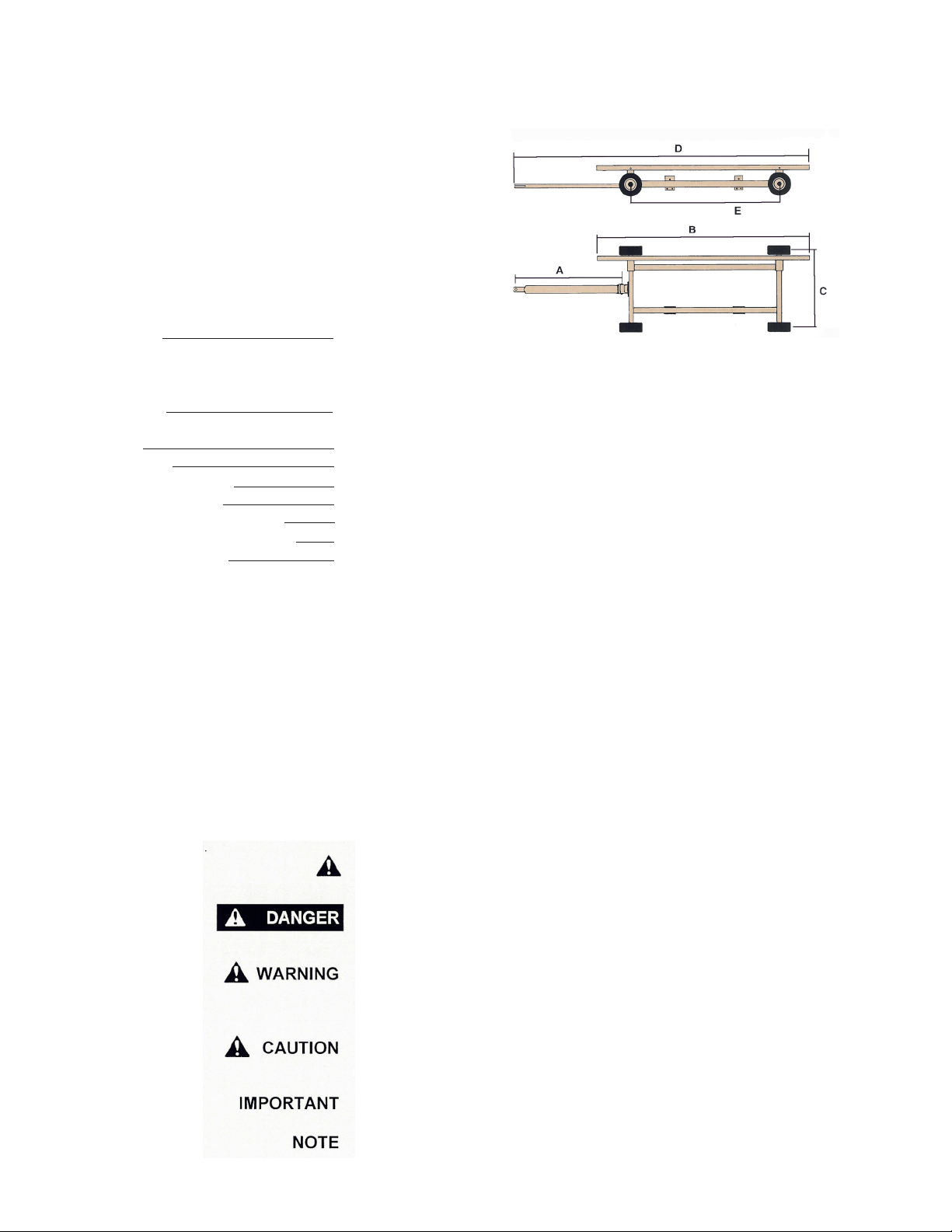
SPECIFICATIONS
DIMENSIONS
HT-874 HT-874L HT -874XL HT-874XL-36
A 12’ 15’ 15’ 15’
B 25’ 30’ 30’ 36’
C 74” 74” 74” 74”
D 31’ 6” 37’ 37’ 9” 40’-9”
E 13’ 15’ 16’ 6” 16’-6”
SPECIFICA TIONS
Weight 1,320 lbs (HT-874)
1,485 lbs (HT-874L)
1,520 lbs (HT-874XL)
1,650 lbs (HT-874XL-36)
Wheels 14 x 6
15 x 6 (HT-874XL-36)
Hu b 6 bolt
Spindles Reinforced 1 3/4” dia.
Axle Construction 6” Box Channel
Steel Upper Bar 4” x 6” steel tubing
Spring Balanced Tongue St andard
Adjustable Header Mounts S tandard
Tie Down S traps S tandard
GENERAL INFORMATION
TO THE OWNER:
The purpose of this manual is to assist you in operating and maintaining your header transport in a safe
manner. Read it carefully . It furnishes information and instructions that will help you achieve years of dependable
performance and help maintain safe operating conditions. If this machine is used by an employee or is loaned
or rented, make certain that the operator(s), prior to operating:
1. Is instructed in safe and proper use.
2. Reviews and understands the manual(s) pertaining to this machine.
Throughout this manual, the term IMPORT ANT is used to indicate that failure to observe can cause damage to
equipment. The terms CAUTION, WARNING and DANGER are used in conjunction with the Safety-Alert
Symbol, (a triangle with an exclamation mark), to indicate the degree of hazard for items of personal safety .
When you see this symbol, carefully read the message that follows and be alert to the possibility of personal
injury or death.
This Safety-Alert symbol indicates a hazard and means
A TTENTION! BECOME ALER T! YOUR SAFETY IS INVOL VED!
Indicates an imminently hazardous situation that, if not avoided, will
result in death or serious injury .
Indicates a potentially hazardous situation that, if not avoided, could
result in death or serious injury , and includes hazards that are
exposed when guards are removed.
Indicates a potentially hazardous situation that, if not avoided, may
result in minor or moderate injury .
Indicates that failure to observe can cause damage to equipment.
Indicates helpful information.
3
Page 4
GENERAL INFORMATION
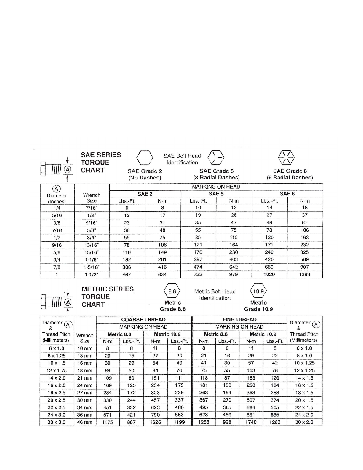
BOLT TORQUE CHART
Always tighten hardware to these values unless a different torque or tightening procedure is listed for a specific
application.
Fasteners must always be replaced with the same grade as specified in the manual parts list.
Always use the proper tool for tightening hardware: SAE for SAE hardware and Metric for metric hardware.
Make sure fastener threads are clean and you start thread engagement properly .
All torque values are given to specifications used on hardware defined by SAE J1701 & J1701M JUL 96.
4
Page 5

TABLE OF CONTENTS
INTRODUCTION 2
EXPRESS WARRANTY 2
SPECIFICATIONS 3
GENERAL INFORMA TION 3
BOLT TORQUE CHART 4
SAFETY RULES 6
SAFETY SIGNS 7
SET-UP INSTRUCTIONS 8
P ARTS LIST 9
LIGHT KIT 10-1 1
ADJ. BRACKETS, TIE-DOWN BRACKETS, HEADER MOUNTS 12
INITIAL OPERA TION, OPERA TING INSTRUCTIONS/MAINTENANCE 13
SERVICE RECORDS 14
5
Page 6

SAFETY RULES
A TTENTION! BECOME ALERT! YOUR SAFETY IS INVOL VED!
Safety is a primary concern in the design and manufacture of our products. Unfortunately , our efforts to provide
safe equipment can be erased by an operator’s single careless act. In addition, hazard control and accident
prevention are dependent upon the awareness, concern, judgement, and proper training of personnel involved in
the operation, transport, maintenance and storage of equipment.
Make certain that the operator(s), prior to operating is instructed in safe and proper use and reviews and
understands the manual(s) pertaining to this machine.
Read this manual before you operate this machine. If you do not understand any part of this manual, or need
more information, contact the manufacturer or your authorized dealer .
SAFETY
Understand that your safety and the safety of other persons is measured by how you service, and operate this
machine. Know the positions and functions of all controls before you try to operate them. Make sure to check
all controls in a safe area before starting you work.
The safety information given in this manual does not replace safety codes, federal, state or local laws. Make
certain your machine has the proper equipment as designated by local laws and regulations.
A frequent cause of personal injury or death is from persons falling of f equipment and being run over. Do not
permit persons to ride on this machine.
Travel speeds should be such that complete control and machine stability is maintained at all times. Where
possible, avoid operating near ditches, embankments and holes. Reduce speed when turning, crossing slopes
and rough, slick or muddy surfaces.
Collision of high speed road traffic and slow moving machines can cause personal injury or death. On roads,
use flasher lights according to local laws. Keep slow-moving-vehicle emblem visible. Pull over to let faster
traffic pass.
Make sure that the header is fastened securely to the transport before moving.
Make sure that everyone is clear of equipment before moving the machine. NEVER position yourself under or
near header when mounting on header transport.
Never adjust, service, clean, or lubricate the header transport until all power is shut off.
Make sure that the header transport is fastened securely to the tractor by using a high strength hitch pin, clip
and safety chains.
Do NOT exceed load limit or speeds in excess of 20 MPH. Rims, hubs and bearings are designed for heavy
loads at slow speeds. Also be sure slow moving vehicle emblem is att ached to rear of the transport.
6
Page 7

SAFETY SIGNS
A TTENTION! BECOME ALERT! YOUR SAFETY IS INVOL VED!
Replace Immediately If Damaged or Missing!
IMPORTANT: Install new safety signs if the old signs are
destroyed, lost, painted over or cannot be read. When
parts are replaced that have safety signs, make sure you
install a new sign with each new part. New signs are
available from the manufacturer or your authorized dealer.
Ref. # Description Part #
Req’d
1 Sign, Caution DC-111 1
2 Sign, Warning DW-108 1
DW-108
DC-111
7
Page 8

SET-UP INSTRUCTIONS
Have tires mounted to wheels according to tire manufacturer’s recommendations.
1.
Remove lug nuts on Back and Front Assemblies. Mount wheels to hubs and fasten lug nut s securely
2.
(80 torque). (Lug nuts should be checked after each load during initial operation of the header transport
and then after every 10 hours of use.)
Attach the Large Lower Bar to the front and back assemblies using eight 1/2” x 4 1/2” bolts and eight
3.
1/2” lock nuts. Attach Small Lower Bar using eight 1/2” x 4 1/2” bolts and eight 1/2” lock nuts.
Attach the Tongue Assembly to the front assembly using 1 1/4” x 1 1 3/4” Tongue Bolt and 1 1/4” hex
4.
nut. Attach one end of the Large T ongue S pring to the top bracket on the tongue assembly . Lift tongue
and loop other end of spring over the mounting bracket on hitch assembly that is attached to the Front
Assembly . If equipped with a Quick-Hitch T ongue Assembly , check to make sure that the safety catch
(7/8” x 2 1/4” bolt with spacer) under the tongue assembly (slide of quick-hitch) is secure.
Remove one 3/8” x 3 1/2” bolt from end of slide channel on axle. Remove 1/2” Slide Bolt Weldments
5.
from Adjustable Bracket and insert into slide channel. Place adjust able bracket over slot on top of both
Slide Bolt Weldments on the front axle assembly . Att ach and secure the 1/2” Handle Nuts with lock
washers. Place the other adjustable bracket over the slot on the top of the back axle assembly and
attach in the same way . Equally space Upper Bar on adjustable bracket support and fasten using two
Upper Bar Clamps, four 1/2” flat washers and four 1/2” lock nuts. Reattach 3/8” x 3 1/2” bolt to end of
slide channel.
Attach the Header Mounts using the Fast Clamp Nut and Bolt. For different mounting positions, refer
6.
to the diagrams at the end of this section. IMPORT ANT : Make sure that the clamping handle is in
the up position for maximum ground clearance before operating the header transport.
Attach the Tie-Down Bracket and Strap Assembly with ratchet to the outside of the Lower Bar. DO
7.
NOT OVER TIGHTEN THE 1/2” BOL TS ON THE TOP OF THE ASSEMBLY , BUT ALLOW THE TIEDOWN BRACKETS TO MOVE FREEL Y ALONG THE LOWER BAR.
P ARTS DIAGRAM
8
Page 9

PARTS LIST
Cone (large) 104579 or LM -48548
St eel Upper Bar (4" x 6" x 36 ') for
# Pa r t # De scrip tion Qty
1 TA -874 Regular Long Tongue for HT-874 1
1 TA -874L Regular Long Tongue for HT-
874L, HT-874XL & HT-874XL-36
2 TB -610 Tongue Bol t 1 1/ 4" Rd x 11 3/ 4" 1
3 HN-114 1 1/4" Hex Nut 4
4 KP-610 Ki ng P i n Verti cal Hi tc h B ol t
1 1/4" x 7 3/ 4"
5 HW-68 Hitch Weldment Complete 1
6 B B-58 5/ 8" ID Bron z e Bus hi ng 4
7 S B-58 S pecial S tep B ol t wi th Nut 4
8 TRE-78L Tie Rod End, Left 2
8 TRE-78R Tie Rod End, Right 2
9 HN-78L 7/8"-14 Nut, Left 2
9 HN-78R 7/8" -14 Nut, Right 2
10 TR-78 Tie Rod, 7/8 " x 24" Rd 2
11L SA-874L 1 3/4" Spindle & "U" Assy, Left 1
11R SA-874R 1 3/4" Spindle & "U" Assy, Right 1
12 BB -114S 1 1/4" ID Bronze B us hi ng 4
13 FA-874 Running Gear, F ront Axle onl y
les s hitch, et c.
14 BA -874 Running Gear, Rear Axle onl y
less Hubs, etc.
15 SS -134678 Spi ndl e, Strt . 1 3/4" Di a. X 6 7/8" 4
16 SB -114 Spi ndl e B olt, 1 1/4" x 9 1/ 4" 2
17 FW -11 4 Fl at W asher, 1 1/4" ID 2
19 TS-615 Large Tongue Spring 1
20 SLB -874 Smal l Lower B ar 2" x 4" x 152"
(HT-874)
20 SLB -874L Sm al l Lower B ar 2" x 4" x 176"
(HT-874L)
20 SLB -874XL Sm al l Lower B ar 2" x 4" x 194"
(HT-874XL; HT-874XL-36)
21 105218 Hub, wi t h st uds, nuts a nd c ups 4
22 103953 Greas e Seal 4
23 104579
Inner
24 104082 Cone (s m al l ) 104082 or
LM-67048 Out e r
25 104580 Cup (large) 104580 or LM-48510 4
26 104081 Cup (s m al l ) 104081 or LM-67010 4
# Pa r t # Descrip tion Qty
27 104581 S pi ndl e Was her 4
1
1
1
1
1
1
1
4
4
28 103289 S l ot ted S pindle Nut 4
29 CP-316 Cott er Pin 4
30 103969 Dus t Cap 4
31 W R-146 Wheel Ri m , 6 hole 14" x 6" 4
31 W R-156 Wheel Ri m , 6 hole 15" x 6" 4
32 4187 St uds (#4187) (1/ 2"-20) 24
33 5552 Lug Nut (#5552) 24
34 1633 Grease F i tti ng 4
35 LLB-874 Large Lower Bar x 152 "
for (HT-874)
35 LLB-874L Large Lower Bar x 176 "
for HT-874L
35 LLB-874XL Large Lower B ar x 194"
for HT-874XL & HT-874XL-36
36 UB-874S St eel Upper Bar (4" x 6" x 24 ')
for HT-874
36 UB-874S XL S teel Upper B ar (4" x 6" x 30')
for HT-874L or HT-874XL
36 UB-874SXL-
36
37 AB-874 Adjust ab l e Brac ket s for Upper
38 HM-874NS Adj us tabl e Header Mounts (with
39 FW -12 1/2" F l at Washer 4
40 12LN 1/2" Loc k Nut 20
41 HP-586 5/8" x 6" Hi tc h P i n w/ l o c king pin 2
42 MB -585 5/ 8" x 5" HHMB 2
43 LN-58 5/8" Lock Nut 2
44 MB -12412 1/2" x 4 1/2" HHM B 16
45 SB-12 1/2" Slide Bolt W eldment 4
46 UBC-2 Upper Bar Cl am p 2
47 12HDN 1/2" Handl e Nut 4
48 12LW 1/2" Loc k Was her 4
49 TDB-2 Tie Down Bracket and Strap
50 MB -38312 3/8" x 3 1/ 2" B ol t w/ Lo ck Nut 4
51 TDS-1 Tie Down Strap and Hook only 2
52 RA-1 Ratchet 2
53 3412P 3/4" x 12" P i n 4
54 78HDN 7/8" Handl e Nut 2
HT-874XL-36
Bar (2 pcs )
decal s) (New St yle)
Assembly
1
1
1
1
1
1
2
2
2
9
Page 10

HEADER TRANSPORT LIGHT KIT AND SMV EMBLEM ASSEMBLY
# Pa r t # De scrip tion Qty
1L RLT-L Light A ssembl y (L/H) 1
1R RLT-R Li ght Ass em bl y (R/H) 1
2 LWH-1 Light Wiri ng Harnes s 1
3 LE -1B Light Enhanc er 1
4 WH-1NC M ai n Wiri ng Harness 1
5 LM B -1 Light Mounting B rack et 1
6 TA-1 Telesc opi ng Arm 1
7 HDN-12 Handle Nut 1
8 E B-1 Ex tensi o n B rack et 1
9 A IS -2 Angle Iron Support 2
10 SMV-1 SMV Emblem 1
11 GR-134 Rubber Grom m et (large) 3
12 WC-1 Wire Clip 1
# Pa r t # De scrip tion Qty
13 RD-A1 Am ber Reflec ti ve Decal 8
14 RD-R1 Red Reflect i ve Decal 2
15 RD-O1 Orange Reflect i ve Decal 2
16 141-CB 1/4" x 1" Bolt 2
17 12114-G5-FB 1/2" x 1 1/ 4" (Gr 5) Flang e B ol t 2
18 125-HB 1/2" x 5" Bolt 4
19 14-LN 1/ 4" Loc k Nut 2
20 12-FN 1/2" F l ange Nut 2
21 12-N 1/2" Nut 4
22 38STS Self Tappi ng Screw (l arge) 1
23 14STS Self Tappi ng Sc rew (s m al l ) 8
24 12-W R 1/2" Regul ar Washer 4
WARNING
* Be sure to adjust lights to within 16” of the furthest extremity of the combine header .
* Be certain all flasher and turn indicator lights are working properly BEFORE incidental highway travel.
10
Page 11

SET-UP INSTRUCTIONS
Place extension bracket at rear end of Upper Bar. Attach using the two angle iron supports and secure with
four 1/2” x 5” bolts, washer and nuts.
Place Light Mounting Bracket at the end of the Extension Bracket Arm so the Light Mounting Bracket is level
or horizontal and extends towards the center of the header transport. Secure using two 1/2” x 1 1/4” Flange
Bolts (Gr 5) and Flange Nuts.
Slide the extendable portion of the Telescoping Arm into Light Mounting Bracket and tighten the Handle Nut
until the bracket is secure. Extend the arm until the light assembly is within 16” of the outer extremity of the
unit.
Mount one light assembly at the end of the Light Mounting Bracket (L/H light) and another assembly at the end
of the Telescoping Arm (R/H light). Secure each light assembly using four small self-tapping screws. Each
light assembly should be mounted so the single amber light is positioned towards the outside of the header,
and the amber and red lights are facing the rearward. Secure the SMV Emblem to the Light Mounting Bracket
using two 1/4” x 1” Bolt and Lock Nuts. Be sure the SMV Emblem remains visible from the rear during
transport.
Place one amber reflective decal at the outward and front side of both the T elescoping Arm and Light Mounting
Bracket as shown. Place one Red and Orange Reflective Decal on the rearward end of the Telescoping Arm
and Light Mounting Bracket. The red reflective decal should be place directly above the orange decal.
Slide the Main Wiring Harness through the rubber grommets of the tongue and into the Upper Bar until the
harness extends through the back end of the Upper Bar. Connect the Main Wiring Harness to the corresponding
plug on the Light Enhancer. Attach the smaller Light Wiring Harness to the remaining plug on the Light
Enhancer. Connect each set of wires on the Light Wiring Harness to each Light Assembly . Securely place the
Light Enhancer and excess wiring inside the Upper Bar to prevent damage from weather or operation.
Place the Wire Clip around the Main Wiring Harness and secure to the rear side of the front axle using the large
self tapping screw provided. Be sure the wiring harness is secured properly to avoid any possible pinch points.
Place the remaining Amber Reflective Decals on the Header Transport as indicated below:
16’ Maximum Spacing 16’ Maximum Spacing16’ Maximum Spacing
SIDE
VIEW
One Amber
Decal must
One Amber Decal must be
within 16’ of the hitch point
of the transport (each side)
Amber
Decal
Amber
Decal
Amber Decal
(visible from front)
be as
rearward as
practical
(each side)
SMV Emblem
TOP
VIEW
Amber
Decal
11
Amber
Decal
Amber Decal
(visible from front)
One Red
above One
Orange
Reflective
Decal (each
side)
Page 12

ADJUSTABLE BRACKET
FOR UPPER BAR (AB-874)
POSSIBLE HEADER MOUNT POSITIONS FOR FRAME,
STAND LEG AND RECTANGULAR FRAME HEADERS
ADJUSTABLE TIE-DOWN BRACKET,
HOOK & STRAP ASSEMBLY (TDB-2)
Possible Header Mount positions for Rectangular Frame
Headers. The Header Mount can be adjusted up, down,
forward or backwards, depending upon the type of header
being transported.
Possible Header Mount positions for Round Frame Headers.
The Header Mount can be adjusted up, down, forward or
backwards, depending upon the type of header being
transported.
Possible Header Mount positions for Stand Leg Headers.
The Header Mount can be adjusted up, down, forward or
backwards, depending upon the type of header being
transported.
12
Page 13

INITIAL OPERATION/MAINTENANCE
WARNING
BE CERT AIN THA T ALL POWER IS SHUT OFF BEFORE SERVICING THE HEADER TRANSPOR T
Before the header transport is put into service:
Has the Slow-Moving Vehicle Emblem been properly positioned at the rear of the header transport?
Have all danger, warning caution and import ant signs been read and understood on the equipment? If employees
or others use or are near this equipment, make sure that they also have read and understood all danger,
warning, caution and important signs on the equipment and have also read the operator’s manual.
Has the header transport been properly fastened to the tractor? Use a good quality hitch pin with clip and
safety chains.
SAFETY CHAIN USER INSTRUCTIONS
a) Secure the safety chain by looping it around the tongue
support located on the underside of the outer tongue. Extend
the chain through the clevis hitch and connect to the towing
machine’s attaching bar .
b) Be sure to run the safety chain through the clevis hitch as
shown. This will provide an intermediate support for the safety
chain.
c) Do Not allow more slack than necessary for articulation
(max. 9 inches)
d) Do Not use any intermediate support as the attaching point.
e) Store the safety chain by securing it around the outer tongue.
f) Replace the safety chain if one or more links or end fittings
are broken, stretched or otherwise damaged or deformed.
Are all braces, bolts, nuts, lug bolts, and lug nuts properly fastened?
Are the rear amber extremity lights properly positioned? Extend lights within 16” of the left and right extremities
of the header.
OPERATING INSTRUCTIONS/MAINTENANCE
Adjust the brackets on the header transport to best fit your make and model header. When mounting the
header, NEVER position yourself under or near the header . Securely fasten the header to the header transport.
After mounting the header on the header transport, turn the front wheels to make sure that the header is
positioned clear of tire movement.
Do not exceed the load and size limits of the unit. Maintain speeds of 20 mph or less.
Keep the tires properly inflated. Both under inflation and over inflation can greatly reduce tire life.
Inspect bracing and welds periodically and repair immediately if needed. Failure to repair could cause extensive
damage and greatly reduce the life of the unit.
Inspect tie rods and replace bronze bushings in the steering assembly when needed.
Repack the bearings in the hub assembly once a year or as needed. Use a good quality bearing lubricant such
as Bearing Gard MK1 or equivalent.
Be sure to check the hub nuts often and keep them properly tightened.
13
Page 14

SERVICE / MAINTENANCE RECORD
DATE DESCRIPTION NOTES
14
 Loading...