

Page 1

MODEL GC31t-1 GRAIN CART ASSEMBLY
PATENTED SINGLE AUGER
GRAIN CARTS
J. & M. Mfg. Co., Inc.
P.O. Box 547 Ft. Recovery, OH 45846
Ph: (419) 375-2376 Fax: (419) 375-2708
www.jm-inc.com
READ MANUAL BEFORE BEGINNING ASSEMBLY
(Rev.5.16.13)
Page 2

STEP - 1
GC31t-1 Grain Cart assembly
Through this assembly if the M10 x 25MM
serrated ange hex bolts are not long
enough in certain situations use the M10 x
35MM serrated ange hex bolts.
Tack Weld or Blue Sticker
For stability set the axle weldment up on blocks using an overhead hoist and chain. The blue sticker or
tack welds on the axle should face the front. For the axle and frame scale option installation instruc-
tions go to steps 3 & 4.
STEP - 2
M24 x 75 MM Bolt
M24 Lock Nut
Attach the main frame. Set the rear end onto the axle and the front end onto another block. Use (8) M24 x
75MM and (8) M24 nylon locking hex nuts to fasten main frame to the axle.
-2-
Page 3

STEP - 3
1”x 5” Bolt
GC31t-1 Grain Cart assembly
-Scale Option-
Left Scale Bar Mount
Weigh Bar (short side
to the inside)
1” Center Locking Nut
1”x 6” Bolt
Axle Weldment
1”x 5” Bolt
1” Center Locking Nut
Right Scale Bar Mount
Set the axle weldment up on blocks. Insert four digistar weigh bars. Use 1” x 6” bolts to attach weigh
bars to axle weldment. Make sure that the arrows on all of the weigh bars are pointing up. Attach
the scale bar mounts to the weigh bars using 1” x 5” bolts. Be sure to use correct scale bar mounts in
correct positions. Use (8) 1” center locking nuts on the bolts.
STEP - 4
M24 x 75 MM Bolt
-Scale Option-
M24 Lock Nut
Set the main frame onto the scale axle using an overhead hoist. Use a drift pin to line up the holes then
attach using (12) M24 x 75 MM hex cap screw bolts and (12) M24 nylon locking hex nuts. Make sure
scale wires are not in a position where they will be cut or smashed.
-3-
Page 4

STEP - 5
M24 Washer
M24 Lock Nut
GC31t-1 Grain Cart assembly
M24 x 75 MM Bolt
Place the front leg onto the main frame using an overhead hoist. Use a drift pin to help line up the holes.
Attach the front leg with (8) M24 x 75MM hex head bolts, M24 washers, and M24 nylon locking nuts.
Note: Do not completely tighten. The legs will need to be able to slide for adjustment in a later step.
STEP - 6
M24 x 75 MM Bolt
M24 Lock Nut
Place the rear leg onto the main frame using an overhead hoist. Use a drift pin to help line up the holes.
Attach the rear leg with (12) M24 x 75MM hex head bolts and (12) M24 nylon locking nuts.
The plate from the main frame then gets squared with the plate from the rear leg. Tighten bolts.
-4-
Page 5

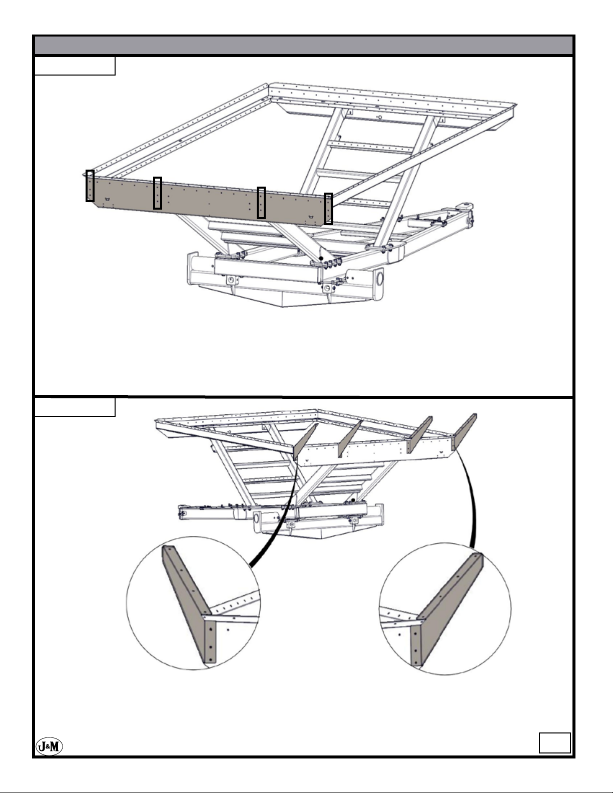
STEP - 7
GC31t-1 Grain Cart assembly
3 Slots
Attach the front rail. Use (8) M10 serrated ange bolts and (8) M10 serrated ange hex head nuts to
attach the front rail to the front leg.
STEP - 8
2 Slots
Attach the rear rail. Use (8) M10 serrated ange bolts and (8) M10 serrated ange hex head nuts
to attach the rear rail to the rear leg.
-5-
Page 6

STEP - 9
GC31t-1 Grain Cart assembly
Attach opposite auger side rail (OAS). Use (4) M10 serrated ange nuts and (4) M10 serrated ange
hex head nuts to attach the OAS to the front and rear rail.
STEP - 10
Attach Auger Side (AS) Rail. Use (4) M10 serrated ange nuts and (4) M10 serrated ange hex
head nuts to attach the AS rail to the front and rear rails.
-6-
Page 7

STEP - 11
GC31t-1 Grain Cart assembly
Measure-
Measure from corner to corner on the rails. Reposition the front leg to get the measurements to be
within 1/8” - 1-4” (3mm-6mm) of each other. Once completed, tighten all bolts to ensure that the
structure remains square. (Do not tighten bolts on the front leg.)
STEP - 12
Attach front rail cross brace. Use (29) M10 serrated ange hex head bolts and (29) M10 serrated hex
ange nuts.
-7-
Page 8
STEP - 13
GC31t-1 Grain Cart assembly
Attach rear rail cross brace. Use (21) M10 serrated ange hex head bolts and (21) M10 serrated hex
ange nuts. Do NOT insert bolts into holes that are surrounded by squares in the gure above.
STEP - 14
Attach the two AS Slope Gussets and two OAS Slope Gussets using (12) 8.8 M10 x 25 MM serrated
ange hex head bolt and M10 serrated ange hex head nuts.
!STOP! It is important to have all bolts and nuts tightened at this point. In the next steps, it will become
hard to access some of the bolts.
-8-
Page 9

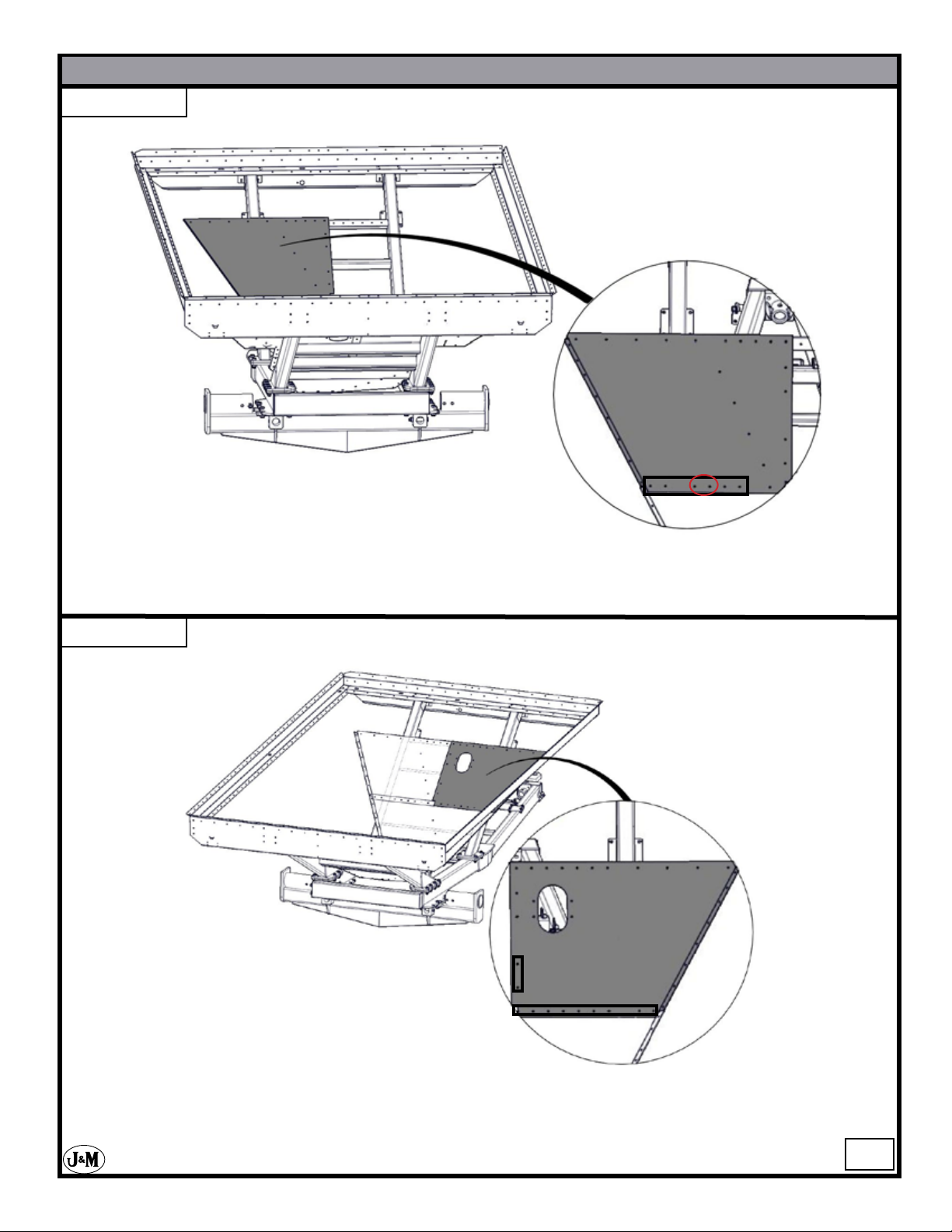
STEP - 15
GC31t-1 Grain Cart assembly
Attach the front lower panel to the front leg as shown. Use (2) temporary M10 serrated ange bolts to
hold the front lower panel in place. Insert bolts into the two holes that are circled.
STEP - 16
Attach the rear bottom panel to the rear leg as shown. Use (2) temporary M10 serrated ange bolts to hold
the rear bottom panel into place.
-9-
Page 10

STEP - 17
GC31t-1 Grain Cart assembly
Attach the OAS lower middle panel. Use (5) 8.8 M10 x 25 MM serrated ange hex head bolts and (5)
M10 serrated ange hex head nuts to attach the OAS lower middle panel. Only insert hardware into
the holes that are inside the outlined area in the gure above.
STEP - 18
Attach the AS lower middle panel. Remove the 2 temporary bolts and use (10) 8.8 M10 x 25 MM ser-
rated ange hex head bolts and (10)M10 serrated ange hex head nuts to attach the AS lower middle
panel. Only insert hardware into the holes that are inside the outlined area in the gure above.
-10-
Page 11
STEP - 19
GC31t-1 Grain Cart assembly
Attach the front AS lower middle panel. Use (6) 8.8 M10 x 25 MM serrated ange hex head bolts and (6)
M10 serrated ange hex head nuts. Only insert hardware into the holes that are inside the outlined
area in the gure above. For the scale option leave out hardware that is inside of the circle.
STEP - 20
Attach the front OAS lower middle panel. Remove the two temporary bolts and use (11) 8.8 M10 x 25
MM serrated ange hex head bolts and (11)M10 serrated ange hex head nuts. Only insert hardware
into the holes that are inside the outlined area in the gure above.
-11-
Page 12

STEP - 21
GC31t-1 Grain Cart assembly
Attach the OAS bottom panel. Use (1) 8.8 M10 x 25 MM serrated ange hex head bolts and (1)M10
serrated ange hex head nuts to attach the OAS bottom panel. Insert the hardware into the hole that is
highlighted in the outlined area in the above gure.
STEP - 22
Attach the OAS bottom panel. Use (1) 8.8 M10 x 25 MM serrated ange hex head bolt and (1)
M10 serrated ange hex head nut to attach the OAS bottom panel. Insert the hardware into the
hole that is highlighted in the outlined area in the gure above. If the front bottom panels have
any sag in them, move your front legs forward. Once nished tighten the front leg.
-12-
Page 13
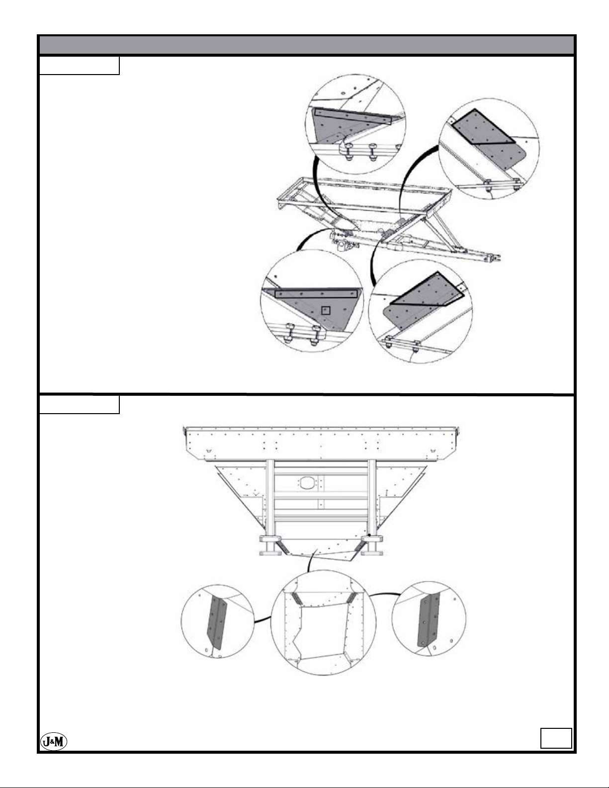
STEP - 23
Attach the Front and Rear Tank Reinforcements. Use (26) M10 x 25 MM
serrated ange hex head bolts and (26)
M10 serrated ange hex head nuts to
attach the Front and Rear Tank Reinforcements.
highlighted in the outlined area.
DO NOt insert bolts that are
GC31t-1 Grain Cart assembly
STEP - 24
Attach the Bottom Panel Corners. Use (12) 8.8 M10 x 25 MM serrated ange hex head bolts and (12)
M10 serrated ange hex head nuts to install the Bottom Panel Corners.
-13-
Page 14

STEP - 25
GC31t-1 Grain Cart assembly
Attach the Wheel Well Corners. Use (4) 8.8 M10 x 25 MM serrated ange hex head bolts and (4) M10
serrated ange hex head nuts.
gure above.
STEP - 26
Attach the AS and OAS
Wheel Wells. For the OAS
Wheel Well use (16) 8.8 M10
x 25 MM serrated ange
hex head bolts and (16)M10
serrated ange hex head nuts
for installation.
hardware into the outlined
area. For the AS Wheel Well
use (17) 8.8 M10 x 25 MM
serrated ange hex head bolts
and (17)M10 serrated ange
hex head nuts for installation.
DO NOt insert
DO NOt insert hardware into the holes that are inside of the outlines in the
-14-
Page 15
STEP - 27
GC31t-1 Grain Cart assembly
Attach the OAS Front Lower Middle Panel. Use (24) 8.8 M10 x 25 MM serrated ange hex head bolts
and (24) M10 serrated ange hex head nuts for installation. DO NOt insert hardware into the holes that
are inside of the outlined area in the gure above.
STEP - 28
Attach the AS Front Lower Middle Panel. Use (23) 8.8 M10 x 25 MM serrated ange hex head
bolts and (23) M10 serrated ange hex head nuts for installation. DO NOt insert hardware into
the holes that are inside of the outlined area in the gure above.
-15-
Page 16

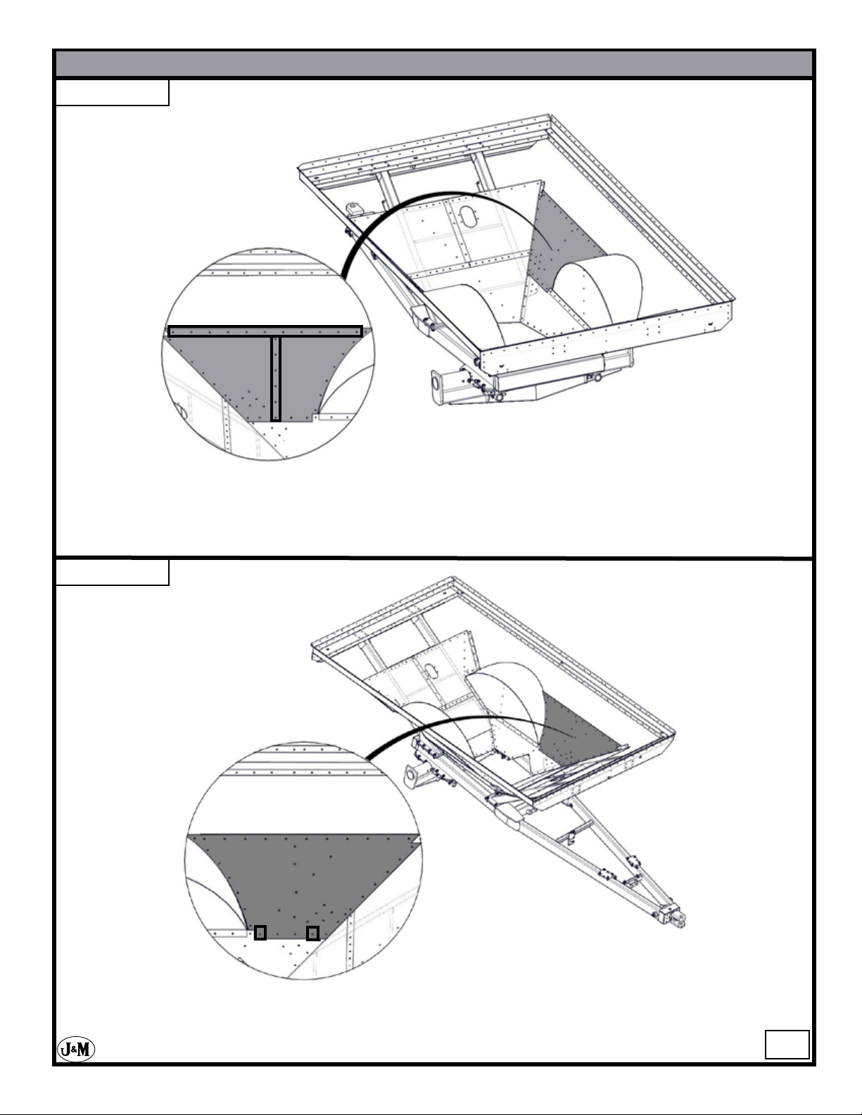
STEP - 29
GC31t-1 Grain Cart assembly
Attach the Rear AS Lower Middle Panel. Use (17) 8.8 M10 x 25 MM serrated ange hex head bolts and
(17) M10 serrated ange hex head nuts for installation.
the gure above.
STEP - 30
DO NOt insert hardware into the outlined area in
Attach the Rear OAS Lower Middle Panel. Use (17) 8.8 M10 x 25 MM serrated ange hex head
bolts and (17) M10 serrated ange hex head nuts for installation. DO NOt insert hardware into the
outlined area in the gure above.
-16-
Page 17

STEP - 31
GC31t-1 Grain Cart assembly
Attach the Front AS Upper Middle Panel. Use (18) 8.8 M10 x 25 MM serrated ange hex head bolts and
(18) M10 serrated ange hex head nuts for installation.
the gure above.
STEP - 32
Attach the Front OAS Upper Middle Panel.
Use (18) 8.8 M10 x 25 MM serrated ange
hex head bolts and (18) M10 serrated ange
hex head nuts for installation. DO NOt insert
hardware into the outlined area in the gure
above.
DO NOt insert hardware into the outlined area in
-17-
Page 18

STEP - 33
GC31t-1 Grain Cart assembly
Attach the AS Front Upper Middle Panel. Use (25) 8.8 M10 x 25 MM serrated ange hex head bolts and
(25) M10 serrated ange hex head nuts for installation. DO NOt insert hardware into the outlined area in
the gure above.
STEP - 34
Attach the Rear OAS Upper Middle Panel. Use (21) 8.8 M10 x 25 MM serrated ange hex head bolts
and (21) M10 serrated ange hex head nuts for installation.
area in the gure above.
DO NOt insert hardware into the outlined
-18-
Page 19

STEP - 35
GC31t-1 Grain Cart assembly
Attach the AS Rear Upper Middle Panel. Use
(27) 8.8 M10 x 25 MM serrated ange hex head
bolts and (27) M10 serrated ange hex head huts
for installation.
outlined area in the gure above.
DO NOt insert hardware into the
STEP - 36
Attach the OAS Front Upper Middle Panel. Use
(23) 8.8 M10 x 25 MM serrated ange hex head
bolts and (23) M10 serrated ange hex head nuts
for installation. DO NOt insert hardware into the
outlined area in the gure above.
-19-
Page 20

STEP - 37
Attach the OAS Center Upper Middle Panel. Use
(23) 8.8 M10 x 25 MM Serrated ange hex head
bolts and (23) M10 Serrated ange hex head nuts
for installation.
outlined area in the gure above.
DO NOt insert hardware into the
GC31t-1 Grain Cart assembly
STEP - 38
Attach the OAS Rear Upper Middle
Panel. Use (27) 8.8 M10 x 25 MM
Serrated ange hex head bolts and
(27) M10 Serrated ange hex head
nuts for installation. DO NOt insert
hardware into the outlined area in the
gure below.
-20-
Page 21

STEP - 39
GC31t-1 Grain Cart assembly
Attach the Rear Sheddar Panels. Use (34) 8.8 M10 x 25 MM serrated ange hex head bolts and (34) M10
serrated ange hex head nuts for installation.
STEP - 40
Attach the clean out door mount using (2) M10 x 25MM serrated ange hex head bolts and (2) M10
serrated ange hex nuts.
-21-
Page 22

STEP - 41
Attach the junction box and display
screen mounts. Use (4)M10 x 25 MM
bolts to mount them both. Attach the
battery box walls with (2) M10 x 25
serrated hex head bolts and (2) M10 nylon locking Nuts. Next attach the battery
box strap with (2) M10 x 50MM hex bolts
and (2) nylon insert locknuts. Now Attach the scale monitor bracket with (2) M6
x 20MM hex head bolts and (2) M6 nylon
locking nuts. Next attach the scale monitor using (2) M6 x 20MM hex head bolts and (2) M6
nylon locking nuts. Finish the battery box with
attaching the cord wrap with (2) M10 x 25MM
serrated hex head bolts and (2) M10 locking nuts.
Next attach the junction box to the junction box
mount using (4) M5 x 20 hex head bolts and (4)
M5 locking nuts.
GC31t-1 Grain Cart assembly
STEP - 42
STOP! Tighten the bolts that are surrounded by the outlined area in the above gure.
These bolts will be inaccessible after the next few steps.
-22-
Page 23

STEP - 43
GC31t-1 Grain Cart assembly
Using an overhead hoist, lift the bottom tube assembly using the lifting hook hole. This should help
set the appropriate angle for laying the assembly into the tank.
STEP - 44
Using an overhead hoist,
lift the bottom tube assembly into the front left corner
of the grain cart. Lower
the bottom tube assembly
until the two corners that
are circled in the gure to
the right to go below the
tank assembly. Then raise
the lower auger back up so
that the two circled corners
can be bolted to the tank.
Attach using (25) M10 x
25 MM serrated hex head
bolts and (25) M10 serrated
hex nuts. Use a drift pin as
needed to help line up the
holes accordingly.
-23-
Page 24

STEP - 45
GC31t-1 Grain Cart assembly
Attach the gearbox top plate. Use (12) M10 x 25MM serrated hex head bolts and (12) M10 ser-
rated hex ange nuts to attach the gearbox top plate to the shell assembly.
STEP - 46
1
3
2
Attach the {1} rear slope splice plate & the {2} side slope splice plate. Use (14) M10 x 25MM
serrated hex head bolts and (14) M10 serrated hex ange nuts to attach them to the gearbox assembly. Attach the {3}inside sheddar panel splice plate. Use (6) M10 x 25MM serrated hex head
bolts and (6) M10 serrated hex ange nuts for attachment. Tighten all splice plates and lower
panels.
-24-
Page 25

STEP - 47
Attach the Shedder Panel/
Gearbox Splice Plate. Use
(14) 8.8 M10 x 25 MM serrated hex head bolts and (14)
M10 serrated hex nuts. (M10
x 35 SF may be needed for
some of the holes.)
GC31t-1 Grain Cart assembly
STEP - 48
Attach the AS Front Top Panel. Use (14) 8.8 M10 x 25 MM serrated ange hex head bolts and
(14) M10 serrated ange hex head nuts for installation.
area in the gure above.
DO NOt insert hardware into the outlined
-25-
Page 26

STEP - 49
Attach the AS Center Top Panel. Use (19) 8.8 M10 x 25 MM serrated ange hex head bolts and (19) M10
serrated ange hex head nuts for installation. DO NOt insert hardware into the outlined area in the gure
above.
GC31t-1 Grain Cart assembly
STEP - 50
Attach the AS Rear Top Panel. Use (8) 8.8 M10 x 25 MM serrated ange hex head bolts and (8) M10
serrated ange hex head nuts for installation. DO NOt insert hardware into the outlined area in the gure
above.
-26-
Page 27

STEP - 51
GC31t-1 Grain Cart assembly
Attach the OAS Front Top Panel. Use (14) 8.8 M10 x 25 MM serrated ange hex head bolts and (14) M10
serrated ange hex head nuts for installation. DO NOt insert hardware into the outlined area in the gure
above.
STEP - 52
Attach the OAS Center Top Panel. Use (19) 8.8 M10 x 25 MM serrated ange hex head bolts and (19) M10
serrated ange hex head nuts for installation. DO NOt insert hardware into the outlined area in the gure
above.
-27-
Page 28

STEP - 53
GC31t-1 Grain Cart assembly
Attach the OAS Rear Top Panel. Use (8) 8.8 M10 x 25 MM serrated ange hex head bolts and (8) M10
serrated ange hex head nuts for installation. DO NOt insert hardware into the outlined area in the gure
above.
STEP - 54
Attach the Front AS Top Panel. Use (9) 8.8 M10 x 25 MM serrated ange hex head bolts and (9)
M10 serrated ange hex head nuts for installation. DO NOt insert hardware into the outlined area
in the gure above.
-28-
Page 29

STEP - 55
GC31t-1 Grain Cart assembly
Attach the Front OAS Top Panel. Use (10) 8.8 M10 x 25 MM serrated ange hex head bolts and (10) M10
serrated ange hex head nuts for installation. DO NOt insert hardware into the outlined area in the gure
above.
STEP - 56
Attach the Rear AS Top Panel. Use (24) 8.8 M10 x 25 MM serrated ange hex head bolts and (24) M10
serrated ange hex head nuts for installation.
area in the gure above.
DO NOt insert hardware into the outlined
-29-
Page 30

STEP - 57
GC31t-1 Grain Cart assembly
Install the Rear OAS Top Panel. Use (26) 8.8 M10 x 25 MM serrated ange hex head bolts and (26) M10
serrated ange hex head nuts for installation. DO NOt insert hardware into the outlined area in the gure
above.
STEP - 58
Install the clean out door. Use (4) M10 x 25MM serrated hex
head bolts and (4) M10 serrated hex ange nuts to attach the
clean out door to the shell assembly.
-30-
Page 31

STEP - 59
Install the following items:
1. (3) Side Gussets
2. Fender Well Wall Support Brace
3. OAS Slope Brace
4. Rear Slope Brace.
Use (56) 8.8 M10 x 25 MM serrated
hex head bolts and (56) M10 serrated
hex nuts. Use (1) M12 hex head bolt
and (1) M12 serrated hex nut in the
outlined area.
GC31t-1 Grain Cart assembly
4
1
2
STEP - 60
4
1
3
5
3
Install the following items:
1. (3)Side Gussets
2. Tank Screen Support Brace
3. Front Side Gussets
4. AS Front Slope Brace
5. Front Slope Brace
Use (52) 8.8 M10 x 25 MM serrated
hex head bolts and (52) M10 serrated
hex nuts. Use (3) M12 hex head bolts
and (3) M12 serrated hex nuts in outlined areas.
Tighten all remaining bolts that are
not yet tightened,
2
-31-
Page 32

STEP - 61
Install the Tank Screen. For
the tank screen cross braces
use (4) M12 x 25 MM serrated hex head bolts and (4)
M12 serrated hex ange nuts.
To assemble the short tank
screen towards the rear of the
cart use (6) 8.8 M10 x 25 MM
serrated hex head bolts and (6)
M10 serrated hex nuts.
GC31t-1 Grain Cart assembly
STEP - 62
Install all three cross braces. Use (15) 8.8 M12 x 25 MM serrated hex head bolts and (15) M12
serrated hex nuts.
-32-
Page 33

STEP - 63
Install front to back cross brace. Use
(4) M12 x 25MM serrated ange
hex head bolts and (4) serrated hex
head nuts to attach the front to back
cross brace. Use (4) more to attach
the side supports for the cross brace.
Where the two front and back cross
braces connect them with an M12 x
300 MM all thread bolt and (4) M12
hex head locking nuts.
GC31t-1 Grain Cart assembly
STEP - 64
Install the AS Small Front Panel
and the Front Top Panel. Use (10)
8.8 M10 x 25 MM serrated hex
head bolts and (10) M10 serrated
hex nuts.
-33-
Page 34

STEP - 65
GC31t-1 Grain Cart assembly
Install the High Front Sideboard. Use (14) 8.8 M10 x 25 MM serrated hex head bolts and (14)
M10 serrated hex nuts
STEP - 66
Install the High Rear Sideboard. Use (11) 8.8 M10 x 25 MM serrated hex head bolts and (11)
M10 serrated hex nuts
-34-
Page 35

STEP - 67
GC31t-1 Grain Cart assembly
Install the Rear End board. Use (16) 8.8 M10 x 25 MM serrated hex head bolts and (16) M10 serrated hex nuts
STEP - 68
Install the Low Rear Sideboard. Use (11) 8.8 M10 x 25 MM serrated hex head bolts and (11)
M10 serrated hex nuts.
-35-
Page 36

STEP - 69
GC31t-1 Grain Cart assembly
Install the Low Front Sideboard. Use (11) 8.8 M10 x 25 MM serrated hex head bolts and (11)
M10 serrated hex nuts.
STEP - 70
Install the Front End board. Use (20) 8.8 M10 x 25 MM serrated hex head bolts and
(20) M10 serrated hex nuts.
-36-
Page 37

STEP - 71
Install all of the Sideboard Corners. Use (34) 8.8 M10 x 25 MM
serrated hex head bolts and (34)
M10 serrated hex nuts.
GC31t-1 Grain Cart assembly
50.5 cm
67.6 cm
20.3 cm
STEP - 72
99.7 cm
Install the ear mount pads. Use (8) M16 x 45 MM bolts and (8) M16 locking nuts to attach the
ear mount pads to the front leg.
-37-
Page 38

STEP - 73
Install front leg support
braces. Use (12) M16 x 45
hex head bolts, (12) M16
washers, and (12) M16
nylon locking nuts.
Use (2) M30 x 120MM
bolts and (2) M30 Nuts to
attach the front leg support
brace to the front leg.
GC31t-1 Grain Cart assembly
STEP - 74
Install the driveshaft assembly with (16) M16
x 45 MM bolts and locknuts without anges.
Only use washers on bolts and nuts for end of
plates that bolt onto the main frame weldment.
Attach the universal joint with a 5/8” x 3” hex
head bolt and lock nut.
-38-
Page 39

STEP - 75
Install the ladder assembly. First attach the
ladder brackets to the front panels. Use (2)
M10 x 25MM serrated hex head bolts and
(2) M10 locking nuts. Now install the ladder.
Attach the top of the ladder to the brackets
using (2) M10 x 25MM serrated hex head
bolts and (2) M10 locking nuts. Use the same
hardware to attach the ladder to the bottom
brackets which are welded to the frame.
Right Ladder
Bracket
GC31t-1 Grain Cart assembly
STEP - 76
Install drive line shield. Use
(3) M10 x 25MM serrated hex
head bolts and (3) M10 serrated
hex ange nuts to attach the
drive line shield to the frame.
-39-
Page 40

STEP - 77
Install all three windows. The top window assembly consists of the window and window seal. The front
and rear lower windows take (4) M10 x 25MM serrated hex head bolts and (4) M10 locking nuts, window, window seal, (2) inner brackets, and (2) outer brackets. Start by inserting the window seal into the
opening followed by the window. Then attach both the inner and outer brackets with their hardware. The
window should be on the inside of the cart when the installation is nished.
GC31t-1 Grain Cart assembly
STEP - 78
Install U-joint guard. Use (2) M10 serrated hex head bolts and (2) M10 serrated hex ange nuts to attach
the U-joint guard to the gearbox assembly.
-40-
Page 41

STEP - 79
Install the Sideboard Brace. Use
(12) M10 serrated hex head bolts
and (12) serrated hex nuts to attach
the sideboard brace gussets. To install the brace use (4) M12 serrated
hex head bolts and (4) serrated Hex
nuts.
GC31t-1 Grain Cart assembly
STEP - 80
Adjustable Auger
Rest Pad
Adjustable Auger
Rest
Install the adjustable auger rest pad. Use (4) M10 x 25 MM serrated hex head bolts and (2) M10 serrated
hex ange nuts. Next attach the adjustable auger rest. Use (2) M10 x 40 MM, (2) M10 washers, and (2)
M10 nylon lock nuts. Do not tighten the bolts. This will need to be adjusted in the next step.
-41-
Page 42

STEP - 81
Install the auger top tube
assembly and pivot pin with
M16 x 45 MM hex bolts and
nylon lock nuts extra large
washers and lock washers.
Be sure to match numbers
that are welded on the
hinge plates of both the
bottom and top tub assemblies (if top tube has a
7 it goes with the bottom
tube that has a 7). Now
set the adjustable auger rest.
Once it is set drill through
the remaining four holes and
use (4) M10 x 40 MM hex
head bolts, (4) washers, and
(4) nylon lock nuts.
GC31t-1 Grain Cart assembly
STEP - 82
Install the bafe hinge. Use (6)
M6 x 20MM bolts, locknuts, and
washers.
Adjust auger rest pad.
Move the rest pad up
or down until both
circled points in the
image above are touching the rest pad. Then
drill through the shell
in the remaining holes.
Use (4) M10 x 40 hex
bolts and (4) M10 nylon
locking hex nuts.
-42-
Page 43

STEP - 83
M12 x 50 MM
bolt goes on the
top and bottom of
the ow control
spout
GC31t-1 Grain Cart assembly
Use an overhead hoist and lift strap to install the ow control spout assembly. Use (2) M12 x 50MM bolts
and hex locknuts. Do not overtighten. The ow control spout assembly needs to be able to pivot freely.
STEP - 84
Install the hydraulic hose holder tank
bracket. Use (2) M10 x 25MM serrated hex head bolts and (2) M10
serrated hex ange nuts to attach the
hose holder to the tank assembly.
Next loosely attach the hydraulic hose
holder ladder bracket. Use (2) M10 x
40MM hex head bolts and (2) M10
nylon lock nuts. The hydraulic hoses
will run between the bracket and the
ladder.
-43-
Page 44

STEP - 85
GC31t-1 Grain Cart assembly
Install the PTO slip clutch assembly. The PTO shaft will need to be shortened depending on the distance
between the tractor PTO shaft and the cart drive line shaft.
STEP - 86
Install the hubs and spindles with 1” x 8” hex head bolt and center lock nuts.
-44-
Page 45

STEP - 87
GC31t-1 Grain Cart assembly
Install the wheels and tires with 3/4” lug nuts. Be sure to tighten and monitor lug nuts to make sure that
they stay tight.
STEP - 88
Install the jack and the black
manual holder. The manual holder
is to be attached on the auger side
of the pto guard. If there are not
holes there already, drill as needed.
Use the manual holder to mark
your holes. Drill through holes
for an M6 bolt. Attach the manual
holder with (2) M6 hex head bolts,
(2) M6 washers and (2) M6 hex
head nuts.
-45-
Page 46

STEP - 89
GC31t-1 Grain Cart assembly
Field Light
(Black Wire)
Amber Flashing
& Turn Signal
(Yellow Wire)
5
Ground
(White Wire)
Tail Light
(Brown Wire)
Amber Flashing
& Turn Signal
(Green Wire)
# Description
1 Main Wiring Harness with 7-Prong Connector End
2 Light Enhancer
3 Wiring Harness for Rear Lights (Each)
4 Extendable Amber Light Assembly (Right Side)
5 Extendable Amber Light Assembly (Left Side)
6 Rear Red Light, Right Side
7 Rear Red Light , Left Side
8 Mercury Switch
9 Field Light Wire
10 Field Light Wire
11 Reective Amber Decal
12 Reective Red Decal
13 Reective Orange Decal
14 Slow Moving Vehicle Emblem
15 Rubber Grommet
16 7-Prong Connecter End Only
17 Amber Light Only
18 Neoprene Clamp
19 Orange Strobe Light
20 Strobe Light Wire
*Right & Left determined by facing the rear of cart.
4
-46-
Page 47

STEP - 90
GC31t-1 Grain Cart assembly
-Non-Scale Option-
1” x 4-1/2” Hex Bolt
2-1/2” Hitch Spindle
2-1/2” Sleeve
Hitch Weldment
2-1/2” Spindle Collar
1” Centerlock Hex Nut
Hitch Plate Weldment
3/4” x 3” Hex Bolt
1” x 7-1/2” Hex Bolt
Assemble the Hitch Spindle Sleeve and Hitch Weldment. Use a 1.0” x 7-1/2” Hex Bolt and a 1” Centerlock
Hex Nut to fasten the two together.
Next attach the Hitch plate Weldment to the grain cart’s A - frame. Use (8) 3/4”-16 x 3.0” Hex Bolts to attach the weldment to the frame.
Now slide the Hitch Spindle through the Hitch Plate Weldment. Slide the Hitch Spindle Collar onto the
Hitch Spindle Sleeve. Fasten the two together using a 1” x 4-1/2” Hex Bolt and a 1” Centerlock Hex Nut.
Fasten all of the hardware once nished.
*When ready for transport, the bolts on the Hitch
Weldment need to be on the bottom side.
-47-
Page 48

STEP - 91
-Scale Option-
GC31t-1 Grain Cart assembly
*Right & Left determined by facing the rear of cart.
Feed the Weigh Bar wire through
the left side of the A-frame, exiting out the grommet hole directly
behind the front leg weldment.
Use 3/4” x 3” Gr 5 bolts to attach
the Weigh Bar Weldment to the
A-frame.
Carefully slide the Weigh Bar
into the Weigh Bar Weldment
and attach it with 1” x 4 1/2” Gr 5
Bolt and locknut. Do not damage
Weigh Bar wire.
1” x 6” Grd 5 Bolt
Swivel Hitch
1”x 4 1/2” Grd 5 Bolt
Weigh Bar Weldment
Weigh Bar
1” Locknut
Attach Swivel Hitch with 1” x 5
1/2” Gr 5 Bolt and locknut to the
Weigh Bar.
STEP - 2
In the Junction Box are 7 connectors. The
connector that is on the left side of the Junction Box needs to be plugged. To install, loosen the connector, insert plug, then retighten.
Note: Run wire from
weigh bar through left
side of frame as shown
3/4” x 3” Grd 8 Bolt
Feed wires from the right side weigh bars as
shown, through adapter plate then through the
frame.
Feed wires from left side weigh bars as shown,
through adapter plate, frame, then through the
cross bar on the frame (as shown in diagram to
the left).
Now all ve wires should be ran to the left hole
above the center cross brace in the A- frame.
Run indicator wire from back of the indicator
to the front center connector of the junction
box.
Run all ve weigh bar wires to the Junction
-Box.
*See image on next page.
Junction Box
Left Weigh Bars
Indicator Wire
Hitch Weigh Bar
Right Weigh Bars
-48-
Page 49

STEP - 92
GC31t-1 Grain Cart assembly
-Scale Option-
Right Front
Right Rear
Left Front
Indicator
Left Rear
Left Front
Right Front
Indicator
Hitch
Left Rear
Hitch
Right Rear
Insert all of the wires into the Junction Box according to the diagram above. Connect the wires to the
terminal of the Junction Box by matching the colored wires.
Weigh-Tronix Digi-Star
Junction Box Wiring Diagram
+Sig = White
-Sig = Red
+Exc = Green
-Exc = Black
Shield = Orange or Orange-White
Junction Box Wiring Diagram
+Sig = White
-Sig = Green
+Exc = Red
-Exc = Black
Shield = Orange
Once nished replace cover of the Junction Box.
Attach the cord wrap around the wires running from the frame
to the Junction Box.
Attach the cord wraps for all four rear weigh bars.
Connect the display screen to the battery. The red wire is to be
run to the positive side (+) and the black wire is to be run to
the negative side (-).
*Right & Left determined by facing the rear of cart.
-49-
Page 50

STEP - 93
GC31t-1 Grain Cart assembly
Attach two 1/4” x 29” (736.6mm)
hydraulic hoses from the shut off gate
cylinder to the tank bulkhead couplings.
STEP - 94
Install the 1/4” x 206” hose to the bottom
(closest) end of cylinder. Install the 1/4” x
222” hose to the top (farthest) end of cylinder.
Attach two 1/4” x 160” (4,064mm)
hydraulic hoses from the tank bulkhead
couplings to the tractor..
-50-
Page 51

STEP - 95
GC31t-1 Grain Cart assembly
-Slider Option-
3
5
# Description
1 1/2” X 1 1/2” Clevis pin w/ cotter pin
2 1/4” St. elbow
3 1/4” x 336’ (8534mm) Hydraulic hose
1/4” x 336’ (9144mm) for Slider Option
4 1/4” Swivel restrictor
5 Hydraulic cylinder w/ clevis end
STEP - 96
1
4
2
HYDRAULIC CYLINDER ASSEMBLY
(To raise and lower the upper auger)
# Description
1 3” bore x 14” stroke hydraulic cylinder
2 1” x 4” Pin with hair pin
3 3/8” Street elbow 90
4 3/8” Street tee
5 Pilot check valve
6 Orice restrictor (.062)
7 1/4” x 9 1/2” (241.3mm) Hydraulic hose
8 1/4” x 206” (5232mm) Hydraulic hose
9 1/4” x 222” (5639mm) Hydraulic hose
-51-
Page 52

STEP - 97
GC31t-1 Grain Cart assembly
-Slider Option-
# Length
1 14” (355,6m)
2 53.50” (1358,9m)
3 9.75” (247,6m)
4 13” (330,2m)
5 73” (1854,2)
6 50.50” (1282,7m)
Attach all of the hoses for the slider option. Attach hose’s accordingly to the image above.
STEP - 98
-Slider Option-
2
3
1
4
5
6
For the slider option the diverter valve will need to be installed. Bolt the diverter valve in place using
(2) M10 serrated hex bolt and (2) M10 serrated hex head nuts. The valve will need to be positioned so
that when the auger “lands” on the auger rest, the valve should engage and the slider tube should begin
to retract in to its shortest position.
-52-
Page 53

STEP - 99
GC31t-1 Grain Cart assembly
Decal location
-53-
Page 54

STEP - 99
GC31t-1 Grain Cart assembly
Decal location
-54-
Page 55

STEP - 99
GC31t-1 Grain Cart assembly
Decal location
STEP - 2
(Top Side of Top Tube)
-55-
 Loading...