

Page 1

OPERATOR’S MANUAL
and Set-Up Instructions for
H Y D R A U L I C
A U G E R - M A T E
AM-1 Auger-Mate
(Briggs/Stratton Motor)
AM-1ES Auger-Mate
(Briggs/Stratton Motor w/Electric Start)
AM-2 Auger-Mate
(Honda Motor)
AM-2ES Auger-Mate
(Honda Motor w/Electric Start)
JMMAN0101 (Rev . 05/16/06)
J. & M. Mfg. Co., Inc.
P.O. Box 547 Ft. Recovery, OH 45846
Ph: (419) 375-2376 Fax: (419) 375-2708
www.jm-inc.com
Page 2

TO THE DEALER:
Read manual instructions and safety rules. Make sure all items on the Dealer’s Pre-Delivery and Delivery Check Lists
in the Operator’s Manual are completed before releasing equipment to the owner.
Online Warranty claims will be denied if the Warranty Registration Card has not been completed and returned.
EXPRESS WARRANTY :
J. & M. Mfg. Co. Inc. warrants against defects in construction or materials for a period of ONE year . We reserve the right
to inspect and decide whether material or construction was faulty or whether abuse or accident voids our guarantee.
Warranty service must be performed by a dealer or service center authorized by J. & M. Mfg. Co. Inc. to sell and/or
service the type of product involved, which will use only new or remanufactured parts or components furnished by J.
& M. Mfg. Co. Inc. Warranty service will be performed without charge to the purchaser for parts or labor based on the
Warranty Labor Times schedule. Under no circumstance will allowable labor times extend beyond the maximum
hours indicated in the Warranty Labor Times schedule for each warranty procedure. The purchaser will be responsible,
however, for any service call and/or transportation of the product to and from the dealer or service center ’s place of
business, for any premium charged for overtime labor requested by the purchaser, and for any service and/or
maintenance not directly related to any defect covered under the warranty. Costs associated with equipment rental,
product down time, or product disposal are not warrantable and will not be accepted under any circumstance.
Each warranty term begins on the date of product delivery to the purchaser. Under no circumstance will warranty be
approved unless (i) the product warranty registration card (attached to the inside of the Operator’s Manual) has been
properly completed and submitted to the equipment manufacturer, and (ii) a warranty authorization number has been
issued by the equipment manufacturer. This Warranty is effective only if the warranty registration card is returned
within 30 days of purchase.
This warranty does not cover a component which fails, malfunctions or is damaged as a result of (i) improper
modification or repair, (ii) accident, abuse or improper use, (iii) improper or insufficient maintenance, or (iv) normal
wear or tear. This warranty does not cover products that are previously owned and extends solely to the original
purchaser of the product. Should the original purchaser sell or otherwise transfer this product to a third party, this
Warranty does not transfer to the third party purchaser in any way. J. & M. Mfg. Co. Inc. makes no warranty , express or
implied, with respect to tires or other parts or accessories not manufactured by J. & M. Mfg. Co. Inc. Warranties for
these items, if any, are provided separately by their respective manufacturers.
THIS WARRANTY IS EXPRESSL Y IN LIEU OF ALL OTHER W ARRANTIES OR CONDITIONS, EXPRESS, IMPLIED OR
STATUTORY, INCLUDING ANY IMPLIED WARRANTY OF MERCHANTABILITY OR FITNESS FOR PARTICULAR
PURPOSE.
In no event shall J. & M. Mfg. Co. Inc. be liable for special, direct, incidental or consequential damages of any kind. The
exclusive remedy under this Warranty shall be repair or replacement of the defective component at J. & M. Mfg. Co.
Inc’s. option. This is the entire agreement between J. & M. Mfg. Co. Inc. and the Owner about warranty and no J. & M.
Mfg. Co. Inc. employee or dealer is authorized to make any additional warranty on behalf of J. & M. Mfg. Co. Inc.
The manufacturer reserves the right to make product design and material changes at any time without notice. They
shall not incur any obligation or liability to incorporate such changes and improvements in products previously sold to
any customer, nor shall they be obligated or liable for the replacement of previously sold products with products or
parts incorporating such changes.
SERVICE:
The equipment you have purchased has been carefully manufactured to provide dependable and satisfactory use.
Like all mechanical products, it will require cleaning and upkeep. Lubricate the unit as specified. Observe all safety
information in this manual and safety signs on the equipment.
For service, your authorized J. & M. dealer has trained mechanics, genuine J. & M. service parts, and the necessary
tools and equipment to handle all your needs.
Use only genuine J. & M. service parts. Substitute parts may void the warranty and may not meet standards required
for safe and satisfactory operation. Record the model number and serial number of your equipment in the spaces
provided:
ENGINE SAFETY AND W ARRANTY :
Warranty issues regarding the engine or its components are to be directed to the engine manufacturer. Refer to the
engine manufacturers owners manual for safety, operation and warranty instructions.
Page 3
GENERAL INFORMATION
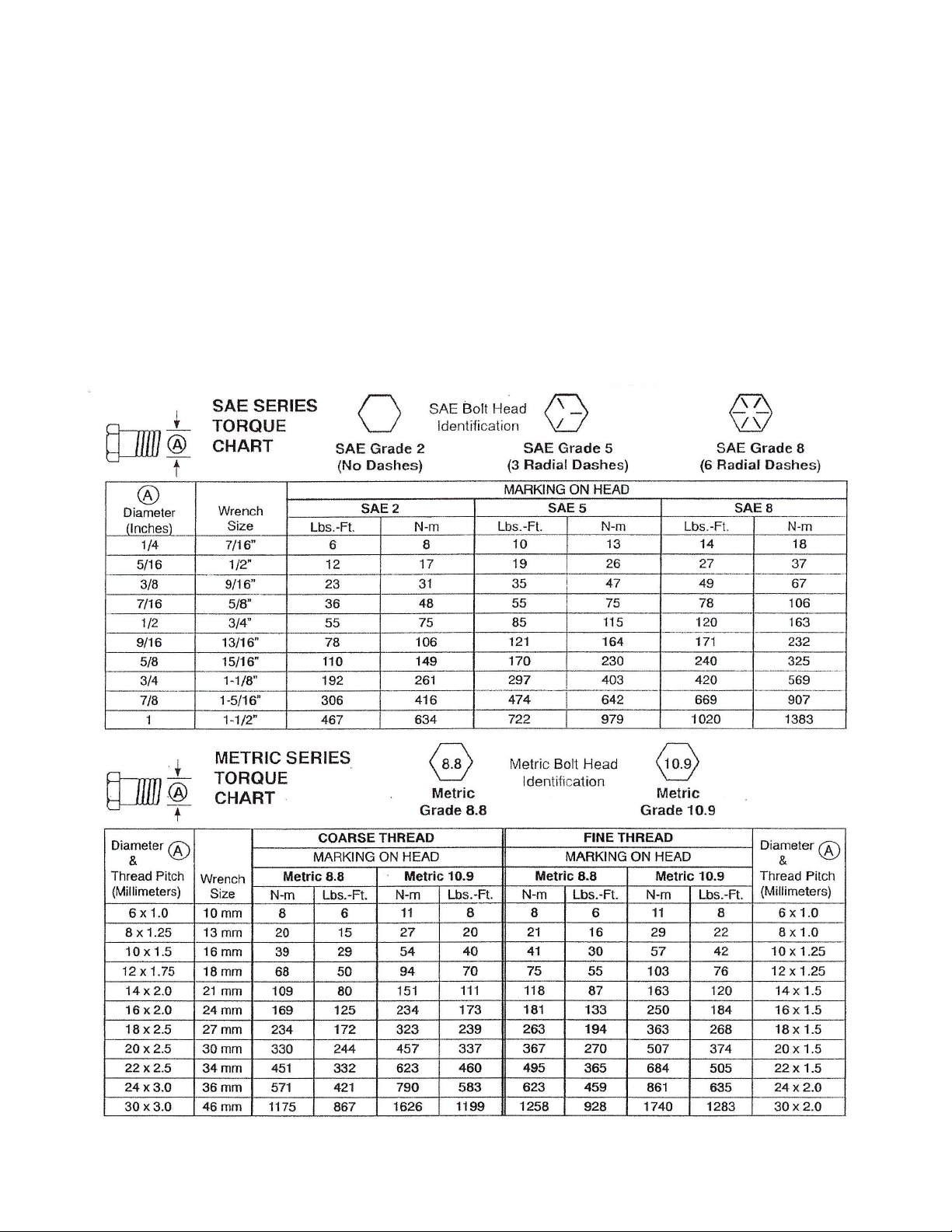
BOLT TORQUE CHART
Always tighten hardware to these values unless a different torque or tightening procedure is listed for a specific
application.
Fasteners must always be replaced with the same grade as specified in the manual parts list.
Always use the proper tool for tightening hardware: SAE for SAE hardware and Metric for metric hardware.
Make sure fastener threads are clean and you start thread engagement properly .
All torque values are given to specifications used on hardware defined by SAE J1701 & J1701M JUL 96.
3
Page 4

TABLE OF CONTENTS
EXPRESS WARRANTY 2
BOLT TORQUE CHART 3
SAFETY SIGNS 5
SAFETY RULES 5- 6
INITIAL OPERA TION 6
P ARTS LIST 7
SET-UP INSTRUCTIONS 8
SERVICE RECORDS 10
4
Page 5

SAFETY SIGNS
A TTENTION! BECOME ALERT! YOUR SAFETY IS INVOL VED!
Replace Immediately If Damaged or Missing!
IMPORTANT: Install new safety signs if the old signs are
destroyed, lost, painted over or cannot be read. When parts
are replaced that have safety signs, make sure you install a
new sign with each new part. New signs are available from
the manufacturer or your authorized dealer.
Ref. # Description Part #
1 Warning, Fluid DD-AH1
2 Caution, Control Valve DC-AH2
3 Decal, Start Engine DI-AH3
IMPORT ANT:
Refer to Engine
Manufacturer’s
Owner’s Manual for
engine Safety
Decals and Safety
Instructions.
TO THE OWNER:
The purpose of this manual is to assist you in operating and maintaining your gravity box in a safe manner.
Read it carefully. It furnishes information and instructions that will help you achieve years of dependable
performance and help maintain safe operating conditions. If this machine is used by an employee or is loaned
or rented, make certain that the operator(s), prior to operating:
1. Is instructed in safe and proper use.
2. Reviews and understands the manual(s) pertaining to this machine.
Throughout this manual, the term IMPORT ANT is used to indicate that failure to observe can cause damage to
equipment. The terms CAUTION, WARNING and DANGER are used in conjunction with the Safety-Alert
Symbol, (a triangle with an exclamation mark), to indicate the degree of hazard for items of personal safety .
When you see this symbol, carefully read the message that follows and be alert to the possibility of personal
injury or death.
This Safety-Alert symbol indicates a hazard and means
A TTENTION! BECOME ALER T! YOUR SAFETY IS INVOL VED!
Indicates an imminently hazardous situation that, if not avoided, will
result in death or serious injury .
Indicates a potentially hazardous situation that, if not avoided, could
result in death or serious injury , and includes hazards that are
exposed when guards are removed.
Indicates a potentially hazardous situation that, if not avoided, may
result in minor or moderate injury .
Indicates that failure to observe can cause damage to equipment.
Indicates helpful information.
SAFETY RULES
A TTENTION! BECOME ALERT! YOUR SAFETY IS INVOL VED!
Safety is a primary concern in the design and manufacture of our products. Unfortunately , our efforts to provide
safe equipment can be erased by an operator’s single careless act. In addition, hazard control and accident
prevention are dependent upon the awareness, concern, judgement, and proper training of personnel involved in
the operation, transport, maintenance and storage of equipment.
Make certain that the operator(s), prior to operating is instructed in safe and proper use and reviews and
understands the manual(s) pertaining to this machine.
Read the manuals before you operate this machine. If you do not understand any part of this manual, or need
more information, contact the manufacturer or your authorized dealer .
Understand that your safety and the safety of other persons is measured by how you service, and operate this
machine. Know the positions and functions of all controls before you try to operate them. Make sure to check
all controls in a safe area before starting your work.
5
Page 6

SAFETY RULES (continued)
A TTENTION! BECOME ALERT! YOUR SAFETY IS INVOL VED!
Hydraulic oil leaking under pressure can penetrate skin and cause infection or other injury .
T o Prevent Personal Injury:
Relieve all pressure, before disconnecting fluid lines.
Before applying pressure, make sure all connections are tight and components are in good condition.
Never use your hand to check for suspected leaks under pressure. Use a piece of cardboard or
wood for this purpose.
If injured by leaking fluid, see you doctor immediately .
Make sure that everyone is clear of equipment before applying power.
CAUTION
This Auger-Mate is designed for use with 6” hydraulic augers up to 15’ in length. For other applications (such
as operating a hydraulic cylinder in a woodsplitter) additional modification of the augermate is required. Do
NOT operate the augermate with a woodsplitter or similar application without proper modifications, as the
Auger-Mate does not have safety check valves or speed control for controlling the cylinder under load.
OPERA TION
For optimum performance from your Auger-Mate, observe the following:
Run the Auger-Mate only in well ventilated areas due to the gasoline engine power .
1
Keep the Auger-Mate clean and free from fertilizer or other chemicals.
2
When used with fertilizer, run the auger empty at the end of each day to eliminate any moisture
3
packing of fertilizer .
MAINTENANCE
The Auger-Mate pump may squeal due to the following conditions:
Low Oil Level
1
Oil is cold. Run the engine for 5 to 10 minutes.
2
Oil tank fill cap is dirty.
3
Large suction hose is bent or shut.
4
Oil filter is dirty and needs replaced.
5
Poor performance may be attributed to the following conditions and indicate immediate service.
Low Power - The relief valve on the control valve may have dirt under the ball.
1
Low Speed - The oil t ank filler breather is dirty and needs cleaned or replaced.
2
Oil Level May Be Low - Fill to withing 1-1/2” of full.
3
Oil Filter Dirty - Replace.
4
INITIAL OPERA TION
6
Page 7

Pi pe S pacer (for mounting on 250-
AUGER-MA TE MOUNTING FRAME PARTS LIST
# Part # Description
1 AM F-1 Mounti n g Fram e
2 AFRP-1 Reinforcing P lat e
3 12EL 1/2" Elbow
4 HH-34 1/2" x 3/4" Hy d. Hose w/ swivel
5 12112HB 1/2" x 1 1/2" Bol t - Grade 5
6 12LN 1/2" Lock Nut
7 FW -12 1/2" F l at Was her
8 BB-2 Battery Box with strap (for
elec t ri c s t art augermat es only)
9 123HB 1/2" x 3" Bolt (for mount i ng on
250-7S gravity box only)
10 PS-1
7S gravity box only)
11 1552HF Hydrauli c Fil ter (NAP A 1552)
12 1078 Filler, Breather & Strainer Assy
13 1074 Tank & F rame Assy
HYDRAULIC PUMP AND MOUNT P ARTS LIST
# Part # Description
1 1094 El bow, 90 Degree (Hi Pressure)
2 1096 Nipple, Transi tion
3 1097 Nipple, Transi tion
4 1098 El bow, 90 Degree
5 1099-G Gasket, Fil ter (part of #6)
6 1099 Fil t er, Replac em ent Elem e nt
7 1100 Cover, Access
8 1104-SS Screw, Set
9 1101 Coupling, Hal f 1"
10 1102 Brac ket, Pum p M t g .
11 1103 Spider
12 1104 Coupling, Hal f 9/ 16"
13 1105 Ring, Adapter
14 1080 Screw, Hex Head
14A 1080-LW Loc kwasher, Shakeproof
15 18-K Key, 1/ 8" (with pum p)
16 1106 Key, 1/ 4" (engine k ey)
HYDRAULIC CONTROL AND HOSES
# Part # Description
1 1085 Control, Direc t i onal
2 1086 Pi n, Headed
3 1087 Pi n, Cot ter
4 SC-A M Screw, Cap
5 1088 Brac ket, Clevis
6 1089 Handle
7 1090 Knob, Ball
8 1091 Hose (Hi P ressure)
9 1092 Hose (Ret urn)
10 1098 El bow, 90 Degree
11 1093 El bow, 90 Degree
12 1094 El bow, 90 Degree (at fil ter)
7
Page 8

INST ALLING THE AUGERMA TE MOUNTING BRACKET
STEP ONE: T o install the Auger-Mate Mounting Bracket, drill four 1/2” holes in the end of the gravity wagon for
each model size indicated below.
MODEL 250-7S or 250-7SB
Drill two sets of 1/2” holes (4 total) 39 1/4” apart
in the end panels as shown. The first set of
holes should be centered and located 2” above
the top of the steel runners of the gravity wagon.
The second set of holes should be located 4”
directly above the first set of holes. (Use the
two pipe spacers to offset the mounting bracket
against the bent lip located above the steel
runners.)
MODEL 385SD
Drill two sets of 1/2” holes (4 total) 39 1/4” apart
in the end panels as shown. The first set of
holes should be centered and located 9 1/2”
above the bend in the end of the gravity wagon
as shown. The second set of holes should be
located 4” directly above the first set of holes.
MODEL 440SD, 540SD, 680SD or 760SD
Drill two sets of 1/2” holes (4 total) 39 1/4” apart
in the end panels as shown. The first set of
holes should be centered and located 12” above
the bend in the end of the gravity wagon as
shown. The second set of holes should be
located 4” directly above the first set of holes.
STEP TWO: Place the Reinforcing Plates behind the legs of the gravity wagon and align. For model 250-7S
wagons, insert two 1/2” x 3” Bolts through each reinforcing plate so the bolt extends to the outside of the end
panel. Slide one 1” Pipe Sp acer on each 1/2” x 3” Bolt and align the Mounting Frame tight against the Pipe
Spacer . Secure the Reinforcing Plate, Pipe S pacers and Mounting Frame to the end panel of the gravity wagon
using 1/2” Lock Nuts. For all other model J&M wagons, use 1/2” x 1 1/2” bolts (without pipe spacers) and place
the Mounting Frame against the wagon.
STEP THREE: Place the Auger-Mate inside the Mounting Bracket and align with the pre-punched holes.
Secure the Auger-Mate to the Mounting Bracket using 1/2” x 1” Bolts, Flat W ashers and Lock Nuts provided.
Install the Operating Handle and 1/2” Elbows on the Auger-Mate, then att ach the 1/2” x 34” Hydraulic Hoses to
both the Auger-Mate and the auger coupler bracket.
STEP FOUR: Fill gasoline tank with fuel. Fill engine with oil per engine manual instructions. Fill Auger-Mate
oil tank with 10W-30 motor oil, or other good grade hydraulic fluid. Fill within 1-1/2” of full tank (approximately
5 gallons required). Start engine per engine manual. Adjust engine throttle to desired speed (select speed
above or below point where maximum engine vibration is noticed). Re-check oil tank level to 1-1/2” from full.
8
Page 9

9
Page 10

SERVICE / MAINTENANCE RECORD
DATE DESCRIPTION NOTES
10
 Loading...