

Page 1
OPERATOR’S MANUAL
and Set-Up Instructions for
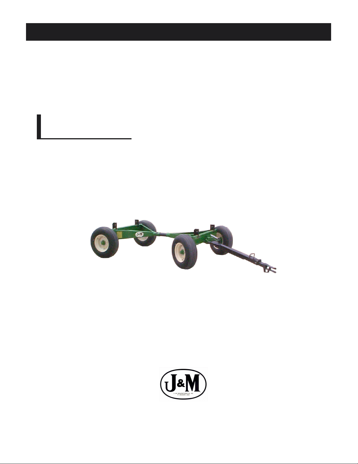
RUNNING GEARS
868 Running Gear
JMMAN0101 (Rev . 08/01/05)
J. & M. Mfg. Co., Inc.
P.O. Box 547 Ft. Recovery, OH 45846
Ph: (419) 375-2376 Fax: (419) 375-2708
www.jm-inc.com
Page 2

TO THE DEALER:
Read manual instructions and safety rules. Make sure all items on the Dealer’s Pre-Delivery and Delivery Check Lists
in the Operator’s Manual are completed before releasing equipment to the owner.
The dealer must complete the Warranty Registration Card attached to the front inside cover of this manual and return
to J. & M. Mfg. Co., Inc. at the address indicated on the card. Warranty claims will be denied if the Warranty
Registration Card has not been completed and returned.
EXPRESS WARRANTY :
J. & M. Mfg. Co. Inc. warrants against defects in construction or materials for a period of ONE year . We reserve the right
to inspect and decide whether material or construction was faulty or whether abuse or accident voids our guarantee.
Warranty service must be performed by a dealer or service center authorized by J. & M. Mfg. Co. Inc. to sell and/or
service the type of product involved, which will use only new or remanufactured parts or components furnished by J.
& M. Mfg. Co. Inc. Warranty service will be performed without charge to the purchaser for parts or labor based on the
Warranty Labor Times schedule. Under no circumstance will allowable labor times extend beyond the maximum
hours indicated in the Warranty Labor Times schedule for each warranty procedure. The purchaser will be responsible,
however, for any service call and/or transportation of the product to and from the dealer or service center ’s place of
business, for any premium charged for overtime labor requested by the purchaser, and for any service and/or
maintenance not directly related to any defect covered under the warranty. Costs associated with equipment rental,
product down time, or product disposal are not warrantable and will not be accepted under any circumstance.
Each warranty term begins on the date of product delivery to the purchaser. Under no circumstance will warranty be
approved unless (i) the product warranty registration card (attached to the inside of the Operator’s Manual) has been
properly completed and submitted to the equipment manufacturer, and (ii) a warranty authorization number has been
issued by the equipment manufacturer. This Warranty is effective only if the warranty registration card is returned
within 30 days of purchase.
This warranty does not cover a component which fails, malfunctions or is damaged as a result of (i) improper
modification or repair, (ii) accident, abuse or improper use, (iii) improper or insufficient maintenance, or (iv) normal
wear or tear. This warranty does not cover products that are previously owned and extends solely to the original
purchaser of the product. Should the original purchaser sell or otherwise transfer this product to a third party, this
Warranty does not transfer to the third party purchaser in any way. J. & M. Mfg. Co. Inc. makes no warranty , express or
implied, with respect to tires or other parts or accessories not manufactured by J. & M. Mfg. Co. Inc. Warranties for
these items, if any, are provided separately by their respective manufacturers.
THIS WARRANTY IS EXPRESSL Y IN LIEU OF ALL OTHER W ARRANTIES OR CONDITIONS, EXPRESS, IMPLIED OR
STATUTORY, INCLUDING ANY IMPLIED WARRANTY OF MERCHANTABILITY OR FITNESS FOR PARTICULAR
PURPOSE.
In no event shall J. & M. Mfg. Co. Inc. be liable for special, direct, incidental or consequential damages of any kind. The
exclusive remedy under this Warranty shall be repair or replacement of the defective component at J. & M. Mfg. Co.
Inc’s. option. This is the entire agreement between J. & M. Mfg. Co. Inc. and the Owner about warranty and no J. & M.
Mfg. Co. Inc. employee or dealer is authorized to make any additional warranty on behalf of J. & M. Mfg. Co. Inc.
The manufacturer reserves the right to make product design and material changes at any time without notice. They
shall not incur any obligation or liability to incorporate such changes and improvements in products previously sold to
any customer, nor shall they be obligated or liable for the replacement of previously sold products with products or
parts incorporating such changes.
SERVICE:
The equipment you have purchased has been carefully manufactured to provide dependable and satisfactory use.
Like all mechanical products, it will require cleaning and upkeep. Lubricate the unit as specified. Observe all safety
information in this manual and safety signs on the equipment.
For service, your authorized J. & M. dealer has trained mechanics, genuine J. & M. service parts, and the necessary
tools and equipment to handle all your needs.
Use only genuine J. & M. service parts. Substitute parts may void the warranty and may not meet standards required
for safe and satisfactory operation. Record the model number and serial number of your equipment in the spaces
provided:
Serial No.: Date of Purchase:
Purchased From:
Provide this information to your dealer to obtain correct repair parts.
2
Page 3

8 TON RUNNING GEAR
SPECIFICATIONS
SPECIFICA TIONS
Capacity 8 T on
Weight (with tires)* 740 lbs
Width (c/c of tire) 68”
Spindle Size 1 3/4” diameter
Spring Balanced T ongue St andard
Ground Height (to top of axle) 23”
Rocking Bolster Optional
Tongue, Adjustable Quick Hitch Standard
Adjustable Center Pole St andard
Wheels - 6 bolt 15 x 6, 16 x 6 or 15 x 8
*Weighed with 11L-15 tires
GENERAL INFORMATION
TO THE OWNER:
The purpose of this manual is to assist you in operating and maintaining your running gear in a safe manner .
Read it carefully. It furnishes information and instructions that will help you achieve years of dependable
performance and help maintain safe operating conditions. If this machine is used by an employee or is loaned
or rented, make certain that the operator(s), prior to operating:
1. Is instructed in safe and proper use.
2. Reviews and understands the manual(s) pertaining to this machine.
Throughout this manual, the term IMPORT ANT is used to indicate that failure to observe can cause damage to
equipment. The terms CAUTION, WARNING and DANGER are used in conjunction with the Safety-Alert
Symbol, (a triangle with an exclamation mark), to indicate the degree of hazard for items of personal safety .
When you see this symbol, carefully read the message that follows and be alert to the possibility of personal
injury or death.
This Safety-Alert symbol indicates a hazard and means
A TTENTION! BECOME ALER T! YOUR SAFETY IS INVOL VED!
Indicates an imminently hazardous situation that, if not avoided, will
result in death or serious injury .
Indicates a potentially hazardous situation that, if not avoided, could
result in death or serious injury , and includes hazards that are
exposed when guards are removed.
Indicates a potentially hazardous situation that, if not avoided, may
result in minor or moderate injury .
Indicates that failure to observe can cause damage to equipment.
Indicates helpful information.
3
Page 4

GENERAL INFORMATION
BOLT TORQUE CHART
Always tighten hardware to these values unless a different torque or tightening procedure is listed for a specific
application.
Fasteners must always be replaced with the same grade as specified in the manual parts list.
Always use the proper tool for tightening hardware: SAE for SAE hardware and Metric for metric hardware.
Make sure fastener threads are clean and you start thread engagement properly .
All torque values are given to specifications used on hardware defined by SAE J1701 & J1701M JUL 96.
4
Page 5

TABLE OF CONTENTS
INTRODUCTION 2
EXPRESS WARRANTY 2
SPECIFICATIONS 3
GENERAL INFORMA TION 3
BOLT TORQUE CHART 4
SAFETY RULES 6
SAFETY SIGNS 7
SET-UP INSTRUCTIONS 7
OPERATION 8
ROUTINE MAINTENANCE 8
P ARTS LIST/DIAGRAM 9
SERVICE RECORDS 10
5
Page 6

SAFETY RULES
A TTENTION! BECOME ALERT! YOUR SAFETY IS INVOL VED!
Safety is a primary concern in the design and manufacture of our products. Unfortunately , our efforts to provide
safe equipment can be erased by an operator’s single careless act. In addition, hazard control and accident
prevention are dependent upon the awareness, concern, judgement, and proper training of personnel involved in
the operation, transport, maintenance and storage of equipment.
Make certain that the operator(s), prior to operating is instructed in safe and proper use and reviews and
understands the manual(s) pertaining to this machine.
Read this manual before you operate this machine. If you do not understand any part of this manual, or need
more information, contact the manufacturer or your authorized dealer .
SAFETY
Understand that your safety and the safety of other persons is measured by how you service, and operate this
machine. Know the positions and functions of all controls before you try to operate them. Make sure to check
all controls in a safe area before starting your work.
The safety information given in this manual does not replace safety codes, federal, state or local laws. Make
certain your machine has the proper equipment as designated by local laws and regulations.
A frequent cause of personal injury or death is from persons falling of f equipment and being run over. Do not
permit persons to ride on this machine.
Travel speeds should be such that complete control and machine stability is maintained at all times. Where
possible, avoid operating near ditches, embankments and holes. Reduce speed when turning, crossing slopes
and rough, slick or muddy surfaces.
Collision of high speed road traffic and slow moving machines can cause personal injury or death. On roads,
use flasher lights according to local laws. Keep slow-moving-vehicle emblem visible. Pull over to let faster
traffic pass.
Never adjust, service, clean, or lubricate running gear until all power is shut off.
Keep all safety shields in place.
Keep hands, feet, hair and clothing away from moving parts while unit is in operation.
Make sure that everyone is clear of equipment before applying power or moving the machine.
Make sure that the running gear is fastened securely to the tractor by using the proper hitch pin, clip and safety
chains.
Never overload the running gear. Overloading the running gear is dangerous and can cause extensive damage.
Do NOT exceed load limit or speeds in excess of 20 MPH. Rims, hubs and bearings are designed for heavy
loads at slow speeds. Also be sure slow moving vehicle emblem is attached to rear of wagon.
Before unhooking the running gear from the towing unit, be sure to properly block the wheels to prevent the cart
from moving.
6
Page 7

750-16 OWNER’S MANUAL
SAFETY SIGNS
A TTENTION! BECOME ALERT! YOUR SAFETY IS INVOL VED!
Replace Immediately If Damaged or Missing!
IMPORTANT: Inst all new safety signs if the old signs are
destroyed, lost, painted over or cannot be read. When
parts are replaced that have safety signs, make sure you
install a new sign with each new part. New signs are
available from the manufacturer or your authorized dealer.
Ref. # Description Part # Req’d
1 Sign, Caution DC-111 1
DC-111
SET-UP INSTRUCTIONS FOR RUNNING GEAR
IMPORTANT: Set-up work to be performed by qualified servicemen only.
Mount tires on the wheels and inflate per the tire manufacturer’s recommendations and instructions.
1)
Mount the wheels to the hubs and tighten the hub nuts to 80 ft. lb. torque. Check the hub nuts after
2)
the first hour of operation, then every 10 hours of operation for the first 40 hours of use. These nuts
must be kept tight at all times. Wheels that are improperly installed on the running gear , resulting in
product failure, will nullify the warranty and shift the burden of liability to the owner/operator of the
equipment.
Slide the coupling pole into the front and back assemblies, slipping the collar in the back assembly .
3)
Sp acing of the coupling pole (approximate distance between holes on the coupling pole) should be 21
1/2”. Distance from center of axle to center of axle is approximately 89”.
Attach the standards (box attachment brackets) to the running gear, unless a rocking bolster is
4)
used.
Fasten the tongue to the front assembly using the tongue bolt (remove paint from the bolt before
5)
attaching) and jam nut. Attach the tongue spring to the bracket on the tongue and hitch assembly.
Check underneath the tongue and make sure that the safety catch (7/8” x 2 1/4” bolt w/spacer) is
secure.
Make sure to properly attach the gravity box (or other equipment) to the running gear. Bolt all four
6)
corners of the gravity box runners to the running gear. (If the box is used in rough terrain and it is not
equipped with a rocking bolster, bolt a minimum of two corners and chain (or cable) the remaining
corners to allow more box flexibility).
7
Page 8

OPERATING INSTRUCTION / MAINTENANCE
BE CERTAIN THAT ALL POWER IS SHUT OFF BEFORE SERVICING EQUIPMENT .
Before equipment is put into service:
Has this manual and the operator’s manual on the gravity box been read and clearly understood by the
operator(s) of this machine?
Have all braces, bolts, nuts, lug bolts, and lug nuts been checked to ensure that they are properly fastened?
Is the running gear properly fastened to the tractor? Use a good quality hitch pin with clip and safety chain.
SAFETY CHAIN USER INSTRUCTIONS
a) Secure the safety chain by looping it around the tongue support located on the underside of the outer
tongue. Extend the chain through the support located on the underside of the inner tongue and connect to
the towing machine’s attaching bar .
b) Be sure to run the safety chain through the support on the underside of the inner tongue. This will
provide an intermediate support for the safety chain.
c) Do Not allow more slack than necessary for articulation (max. 9 inches).
d) Do Not use any intermediate support as the attaching point.
e) Store the safety chain by securing it around the tongue support s.
f) Replace the safety chain if one or more links or end fittings are broken, stretched or otherwise damaged
or deformed.
Have all danger, warning, caution and import ant signs on the equipment been read and clearly understood? If
employees or others use or are near this equipment, make sure that they also have read and understood all
danger, warning caution and important signs on the equipment and have also read the operator’s manual.
750-16 OWNER’S MANUAL
Have the wheel bearings been inspected? Repack with grease if needed. Grease both the tongue bolt and the
hitch bolt.
Do not exceed the load limit of the unit.
SYSTEM REQUIREMENTS:
Tow Loads Safely
Stopping distance increases with speed and weight of towed loads, and on slopes. Towed loads without
brakes that are too heavy for the tractor or are towed too fast can cause loss of control. Consider the total
weight of the equipment and its load.
Observe these recommended maximum road speeds, or local speed limits which may be lower:
If towed equipment does not have brakes, do not travel more than 32 km/h (20 mph) and do not tow
loads more than 1.5 times the tractor weight.
Ensure the load does not exceed the recommended weight ratio. Use additional caution when towing loads
under adverse surface conditions, when turning, and on inclines.
IMPORT ANT:
Keep the tires properly inflated. Both under inflation and over inflation can greatly reduce tire life.
Inspect bracing and welds and repair if needed. Failure to repair could cause extensive damage and greatly
reduce the life of the unit.
Inspect tie rods and replace the bronze bushings in the steering assembly when needed.
Repack the bearings in the hub assemblies once a year or as needed. Use a good quality bearing lubricant
such as Bearing Gard MK1 or equivalent. NOTE: Grease zerks on hub caps are for between scheduled
service lubrication.
8
Page 9

RUNNING GEAR P ARTS LIST
# Part # Description Qty
1 OT-610NS Adj . Tongue Outer Weldme nt 1
2 IT-610NS Adj. Tongue Inner W el d m ent 1
3 TL-610NS Tongue Latch W el dm ent 1
4 SS -615 NS Sm al l S pri ng i n La t ch 1
5 LS-61 0 Latch Pi vot S haft , 1" Dia. 1
6 CP-112 Cotter Pi n 2
7 ST-610 St andard Tongue 1
8 TB-610 Tongue Pivot Bol t 1
9 HN-114 Regu l ar Hex Nut 2
10 KP-610 Ki ng Pin B ol t 1
11 HW-68 Hitc h Weldment 1
12 BB-58 Bronze Bushing, 5/8" 4
13 SB-58 Special S tep Bol t , 5/8" 4
14L TRE -78L Tie Rod End, Left 2
14R TRE -78R Tie Rod End, Right 2
15L HN-78L 7/8"-14 Hex Nut , Left 2
15R HN-78R 7/8"-14 Hex Nut, Rig ht 2
16 TR-2114 Tie Rod, 7/8" Dia. 2
17L S A-78L S pi nd l e & A r m Weldm ent, Left 1
17R S A-78R Spindle & A rm Weldm ent, Ri ght 1
18 EB-134 End S pi ndle Bronze Bus hing 4
19 CP-212 Cotter Pin 2
20 MB-134 M ac h i ne B u s h i ng 2
21 FA-8 Front Ax l e Weldment 1
22 RA-8 Rear Axl e A ss emb ly 1
# Part # Description Qty
23 RS-78 Rear Spindle 2
24 MB-345 3/4" x 5" Bolt 2
25 LN-34 3/4" Hex Loc k Nut 2
26 TS-615 Large Tongue Spring 1
27 CP-3 Coupling P ol e 1
28 ST-68 Standards 4
29 MB-384 3/8" Bolt 8
30 HN-38 3/8" Hex Nut 8
31 CL-312 Collar to Coupling Pole 1
32 105218 Hub includi ng Lug Bolt s & Nut s 4
33 103953 Grease S eal 4
34 104579 Inner Beari ng, Large 4
35 104082 Out er Bearing, S m all 4
36 10 45 81 Washer 4
37 103289 S lo t ted Spi ndl e Nut 4
38 CP-316 Cotter Pin 4
39 103969 Dust Cap 4
40 WR-158 W heel Ri m , 6 Bol t , 15x 8 4
41 4187 Studs (#4187) (1/2"-20) 24
42 78214-BS 7/8" x 2 1/4" HHMB with spacer 1
43 1633 G rease Fi t t i ng 4
44 SB-212 Spa c er Bloc k 2
45 TS B -2 Tongue Spring Bracket (2 pcs ) 1
46 104580 Inner Cup, Large 4
47 104081 Out er Cup, Smal l 4
48 5552 Lug Nut 24
9
Page 10

SERVICE / MAINTENANCE RECORD
DATE DESCRIPTION NOTES
10
 Loading...