

Page 1

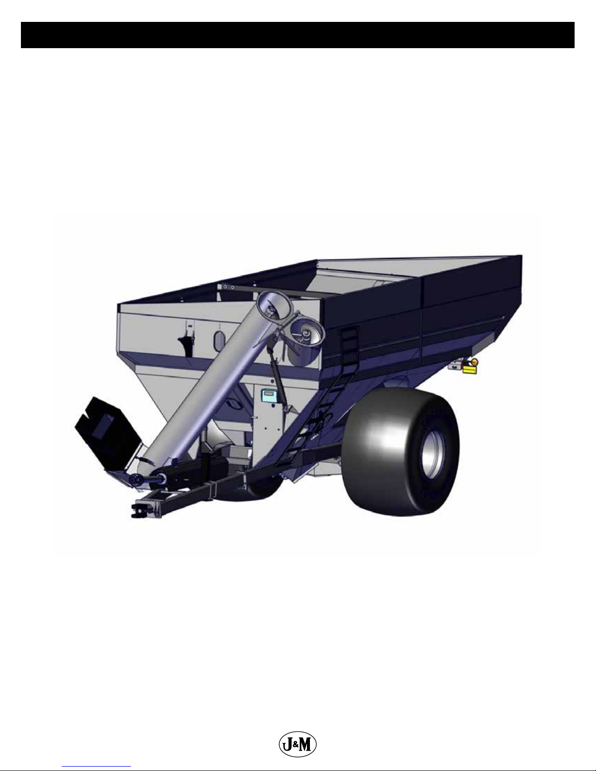
GRAIN CART
Manual
OPERATOR’S MANUAL
MODEL
284 Railroad Street - P.O. Box 547 | Fort Recovery, OH 45846 | Ph: (419) 375-2376 | Fax: (419) 375-2708
Rev. 11.28.2018
J&M Manufacturing Co, Inc
www.jm-inc.com
Page 2
Opposite Auger
Side
Stance
Rear
Front
2
Auger Side
Page 3

Dealer Pre-Delivery Instructions Grain Cart
WHEEL NUTS
Check ALL wheel nuts for correct torque setting. (3/4”-400 Ft-Lbs, 22mm-640 Ft-Lbs)
Tighten as needed. Re-Check wheel nut torque settings during initial break in period
(during 1st, 2nd, 3rd loads, etc.), then periodically afterwards (every 10 hours of use for
rst 40 hours). Keep checking wheel nut settings until wheel nuts do not loosen. If wheel
nuts loosen and damage the surface of the wheel center, it will be impossible to keep
them tight. Failure to keep the wheel nuts tight could cause considerable damage to the
grain cart and surrounding. It is the Dealer’s responsibility to have wheel nuts torqued to
specication before delivery. Damage caused by failure to keep the wheel nuts tight is not
warrantable.
HITCH
Determine the hitch style of cart to be compatible with tractor. Tractor with hammer strap
(clevis type) should be used with grain carts equipped with a single prong (spade) hitch.
Tractors equipped with a single prong hitch (no hammer strap) should be used with grain
carts equipped with a double prong (clevis) hitch.
Be sure the tractor pin is at least 1/4” smaller in diameter than the pin hole in the grain cart
hitch to ensure enough free movement when traversing through uneven terrain.
POWER TAKE-OFF
Check for adequate clearance between telescoping PTO and tractor hitch. Suggested
clearance is 7 inches.
Check telescoping PTO for adequate extension. With the tractor hitched to the cart on at
level ground, the PTO should have approximately 10 inches extended from the collapsed
(shortest) length.
UPPER AND LOWER AUGERS
Raise the auger to the unload position. Run the auger from the PTO or optional hydraulic
motor. If the top auger is misaligned with the bottom auger, you will hear a ‘bang’ as
the upper auger realigns itself with the lower auger. This is normal as the top auger has
dropped to engage the lower auger. Be sure that the top auger engages the lower auger.
Check bearing at top of auger. Be sure to have approximately 1/8” to 3/16” of an inch gap
under/between top auger bearing. Some models have bearings inside and some models
have bearings outside of upper auger housing. If there is no gap under the bearing, or the
gap is greater than 1/8” to 3/16”, the bearing needs adjusted.
HYDRAULIC CYLINDERS AND HOSES
Run all functions of the hydraulic cylinders and inspect ttings and seals for leakage. (use
cardboard or wood to check for hydraulic leaks)
(Continued on Next Page)
3
Page 4

Dealer Pre-Delivery Instructions Grain Cart
GEARBOX
Check the gearbox oil level. For the process of checking the oil in your gearboxes, refer to
“Lubrication Service Schedule” in this manual. Add SAE 80W-90 lubricant as necessary.
LIGHTING & SAFETY FEATURES
Check the tractor lighting system for functions. Plug the grain cart wire harness into the
tractor receptacle and check the cart lighting for correct functions. Note: The auger spout
light is activated through a mercury switch located at the harness connection under the
discharge spout. The auger spout light should automatically turn on when the auger is
in the unload position, and turn o when the auger is returned to the storage position. If
the auger spout light does not turn on or shut o properly, the mercury switch may need
repositioned.
Check that the safety chains are properly installed. Use bolt-torque chart listed in
operator’s manual for correct torque value.
TIRES
All tires need to be inated to the specied air pressure given in the “Tire Pressure” section
on the “Initial Operation & Maintenance” page of this manual.
4
Page 5

Table Of Contents
6 ....................................................................................To the Dealer
7 .............................................................................General Information
8 ...................................................................................Specications
8 .....................................................................................Dimensions
9 ............................................................................... Bolt Torque Chart
10-11 ......................................................................................Decals
12 ....................................................................................Safety Rules
13 ..............................................................Initial Operation and Maintenance
14-15 ...................................................................... Operating Instructions
15 .............................................................Walking Tandem Dual Row Spacing
16 ...................................................................Lubrication Service Schedule
17 .......................................................................... Routine Maintenance
17 ...............................................................................Troubleshooting
18 ..................................................................Adjusting the Lower Flighting
18 ......................................................................Adjusting Upper Flighting
19 ....................................Removing Dirt from the Restrictors on the Hydraulic Cylinder
19 ............................................................................Storage Preparation
19 ........................................................................Removing From Storage
Repair Parts & Diagrams
20 ....................................................................................Wheel Rims
20 ...........................................................................................Tires
21 .................................................................Hub & Spindle Assembly W-891
22 .................................................................Hub & Spindle Assembly W-881
23 ...........................................................Power Take-O (PTO) Shaft Assembly
24-25 ..............................................................130 Degree Gearbox Assembly
26 ................................................................................ Hitch Assembly
27 ............................................................................Drive Line Assembly
28 .........................................................................Lower Auger Assembly
29 ...........................................................................Upper Auger Linkage
30-31 ......................................................................Upper Auger Assembly
32-33 .................................................................Hydraulic Hoses & Cylinders
34-35 ....................................................................... Auto-Gate Hydraulics
36 .................................................................. Auto-Gate Shut-O Assembly
36 ...........................................................Auto-Gate Shut-O Wiring Schematic
37 .............................................................................. Lights and Wiring
38 ......................................Digi-Star 5-Point Scale System for Single Wheel Grain Carts
39 .......................................................Digi-Star 5-Point Scale System with Tracks
40 .................................Digi-Star 5-Point Scale System Hardware for Track & Bolt on Axle
41 .................Digi-Star 5-Point Scale System for Grain Carts with Walking Tandem Dual Wheels
42 ......................................................... Walking Tandem Dual Wheel Assembly
43 .....................................................................................Sideboards
44 ............................................................................Inspection Windows
44 ..........................................................................Door Wheel Assembly
45 ...............................................................................Ladder Assembly
46 ...........................................................................Auger Rest Assembly
47 ........................................................................Spring Return Assembly
48-49 ..........................................................................Roll Tarp Assembly
5
Page 6

To the Dealer
Read manual instructions and safety rules. Make sure all items on the Dealer’s Pre-Delivery and Delivery Check Lists are completed
before releasing equipment to the owner.
The dealer must complete the Warranty Registration found on the Dealer Portal website located at dealer.jm-inc.com. and return
it to J. & M. Mfg. Co., Inc. at the address indicated on the form. Warranty claims will be denied if the Warranty Registration has not
been submitted.
EXPRESS WARRANTY:
J. & M. Mfg. Co. Inc. warrants against defects in construction or materials for a period of ONE year. We reserve the right to inspect
and decide whether material or construction was faulty or whether abuse or accident voids our guarantee.
Warranty service must be performed by a dealer or service center authorized by J. & M. Mfg. Co., Inc. to sell and/or service the type
of product involved, which will use only new or remanufactured parts or components furnished by J. & M. Mfg. Co., Inc. Warranty
service will be performed without charge to the purchaser for parts or labor based on the Warranty Labor Times schedule. Under no
circumstance will allowable labor times extend beyond the maximum hours indicated in the Warranty Labor Times schedule for each
warranty procedure. The purchaser will be responsible, however, for any service call and/or transportation of the product to and
from the dealer or service center’s place of business, for any premium charged for overtime labor requested by the purchaser, and
for any service and/or maintenance not directly related to any defect covered under the warranty. Costs associated with equipment
rental, product down time, or product disposal are not warrantable and will not be accepted under any circumstance.
Each warranty term begins on the date of product delivery to the purchaser. Under no circumstance will warranty be approved
unless (i) the product warranty registration card has been properly completed and submitted to the equipment manufacturer, and
(ii) a warranty authorization number has been issued by the equipment manufacturer. This Warranty is eective only if the warranty
registration card is returned within 30 days of purchase.
This warranty does not cover a component which fails, malfunctions or is damaged as a result of (i) improper modication or
repair, (ii) accident, abuse or improper use, (iii) improper or insucient maintenance, or (iv) normal wear or tear. This warranty
does not cover products that are previously owned and extends solely to the original purchaser of the product. Should the original
purchaser sell or otherwise transfer this product to a third party, this implied, with respect to tires or other parts or accessories not
manufactured by J. & M. Mfg. Co., Inc. Warranties for these items, if any, are provided separately by their respective manufacturers.
THIS WARRANTY IS EXPRESSLY IN LIEU OF ALL OTHER WARRANTIES OR CONDITIONS, EXPRESS, IMPLIED OR STATUTORY, INCLUDING
ANY IMPLIED WARRANTY OF MERCHANTABILITY OR FITNESS FOR PARTICULAR PURPOSE.
In no event shall J. & M. Mfg. Co., Inc. be liable for special, direct, incidental or consequential damages of any kind. The exclusive
remedy under this Warranty shall be repair or replacement of the defective component at J. & M. Mfg. Co., Inc’s. option. This is the
entire agreement between J. & M. Mfg. Co., Inc. and the Owner about warranty and no J. & M. Mfg. Co., Inc. employee or dealer is
authorized to make any additional warranty on behalf of J. & M. Mfg. Co., Inc.
The manufacturer reserves the right to make product design and material changes at any time without notice. They shall not incur
any obligation or liability to incorporate such changes and improvements in products previously sold to any customer, nor shall
they be obligated or liable for the replacement of previously sold products with products or parts incorporating such changes.
SERVICE:
The equipment you have purchased has been carefully manufactured to provide dependable and satisfactory use. Like all
mechanical products, it will require cleaning and maintenance. Lubricate the unit as specied. Observe all safety information in
this manual and safety signs on the equipment.
For service, your authorized J. & M. dealer has trained mechanics, genuine J. & M. service parts, and the necessary tools and
equipment to handle all your needs.
Use only genuine J. & M. service parts. Substitute parts may void warranty and may not meet standards required for safety and
satisfactory operation. Record the model number and serial number of your equipment in the spaces provided:
Model No:1012 Serial No: ________________________ Date of Purchase: ___________________
Purchased From: ________________________________________________________________________________
Provide this information to your dealer to obtain correct repair parts.
6
Page 7

General Information
TO THE OWNER:
The purpose of this manual is to assist you in operating and maintaining your grain cart in a safe manner. Read it carefully. It
furnishes information and instructions that will help you achieve years of dependable performance and help maintain safe operating
conditions. If this machine is used by an employee or is loaned or rented, make certain that the operator(s), prior to operating:
1. Is instructed in safe and proper use.
2. Reviews and understands the manual(s) pertaining to this machine.
Throughout this manual, the term IMPORTANT is used to indicate that failure to observe can cause damage to equipment. The
terms CAUTION, WARNING and DANGER are used in conjunction with the Safety-Alert Symbol (a triangle with an exclamation mark)
to indicate the degree of hazard for items of personal safety. When you see this symbol, carefully read the message that follows and
be alert to the possibility of personal injury or death.
This Safety-Alert symbol indicates a hazard and means ATTENTION!
BECOME ALERT! YOUR SAFETY IS INVOLVED!
DANGER
WARNING
CAUTION
IMPORTANT
NOTE
Indicates an imminently hazardous situation that, if not avoided, will
result in death or serious injury.
Indicates a potentially hazardous situation that, if not avoided, will
result in death or serious injury, and includes hazards that are exposed
when guards are removed.
Indicates a potentially hazardous situation that, if not avoided, may
result in minor or moderate injury.
Indicates that failure to observe can cause damage to equipment.
Indicates helpful information.
7
Page 8
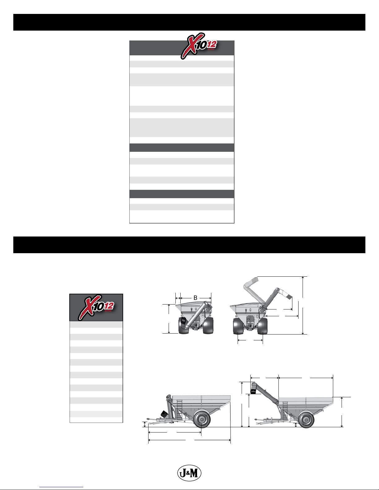
Specications
SPECIFICATIONS
Single Wheel Option
Capacity
Auger, One Vertical
Unload Time (minutes)
(2)
Wheels
Tires (2)
Hubs (2)
Spindles (2)
Tongue Weight
Empty
Loaded
Total Weight (approx.)
Walking Tandem Dual Wheels Option
Capacity
Wheels (4)
Tires (4)
Spindles (4)
Total Weight (approx.)
Tracks Option
Capacity
Total Weight (approx.)
Compaction Rate
Compaction Rate LT Series
1,025 Bushels
20” Bullet
1.8 minutes
30x32, 31x32,
32x36 or 44x32
900/60R32, 35.5x32,
1050/50R32, or
1250/50R32
10 Bolt
4 1/2” (Stress-Proof)
2,900 lbs.
4,200 lbs.
12,900 lbs.
1,000 Bushels
16x42, 18x38, 18x42
480/80R42, 520/85R38
or 520/85R42
4 1/2” Diameter
16,100 lbs.
1,050 Bushels
21,300 lbs.
9.93 lbs/sq inch
13.91 lbs/sq inch
Dimensions
C
B
D
A
B
C
D
E
F
G
H
I
J
K
L
M
N
O
P
10’-11”
11’-9”
NA
10’-10”
13’-6”
10’-0”
22’-3”
1’-6”
20’-1”
30’-7”
13’-6”
22’-0”
12’-0”
1’-5”
11’-2”
18’-2”
A
F
P
K
E
Eective Side Reach
(throw)
H
I
J
G
LO
M
N
8
Page 9
General Information
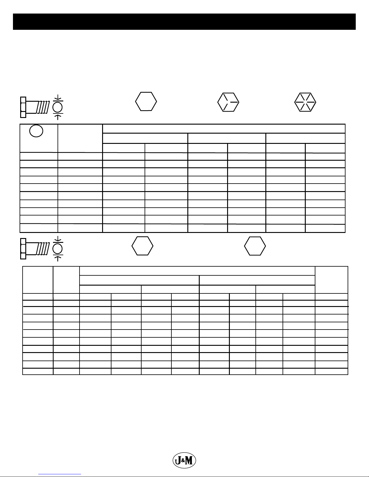
SAE SERIES
BOLT TORQUE CHART
Always tighten hardware to these values unless a dierent torque or tightening procedure is listed for specic application.
Fasteners must always be replaced with the same grade as specied in the manual parts list.
Always use the proper tool for tightening hardware: SAE for SAE hardware and Metric for Metric hardware.
Make sure fastener threads are clean and you start thread engagement properly.
All torque values are given to specications used on hardware dened by SAE J1701 & J1701M (JUL 96)
SAE Bolt Head
8
17
31
48
75
106
149
261
416
634
Identication
Metric Bolt Head
Identication
8
20
40
70
111
173
239
337
460
583
1199
SAE Grade 5
3 Radial Dashes
MARKING ON HEAD
SAE 5 SAE 8
LBS.-FT.
10
19
35
55
85
121
170
297
474
722
8
21
41
75
118
181
263
367
495
623
1258
N-m N-m
13
26
47
75
115
164
230
403
642
979
MARKING ON THREADMARKING ON THREAD
6
16
30
55
87
133
194
270
365
459
928
10.9
Metric
Grade 10.9
11
29
57
103
163
250
363
507
684
861
1740
LBS.-FT.N-m
1020
Metric 10.9Metric 8.8Metric 8.8 Metric 10.9
SAE Grade 8
6 Radial Dashes
14
27
49
78
120
171
240
420
669
635
1283
22
42
76
120
184
268
374
505
18
37
67
106
163
232
325
569
907
1383
Diameter
(Millimeters)
Thread Pitch
8
10 x 1.25
30 x 2.0
A
Diameter
(Inches)
1/4
5/16
3/8
7/16
1/2
9/16
5/8
3/4
7/8
1
Diameter
&
(Millimeters)
Thread Pitch
6 x 1.0
8 x 1.25
10 x 1.5
12.1.75
14 x 2.0
16 x 2.0
18 x 2.5
20 x 2.5
22 x 2.5
24 x 3.0
30 x 3.0
TORQUE
A
CHART
Wrench
Size
7/16”
1/2”
9/16”
5/8”
3/4”
13/16”
15/16”
1-1/8”
1-5/16”
1-1/2”
METRIC SERIES
TORQUE
A
CHART
Wrench
Size
10 mm
13 mm
16 mm
18 mm
21 mm
24 mm
27 mm
30 mm
34 mm
36 mm
46 mm
1175
68
109
169
234
330
451
571
SAE Grade 2
(No Dashes)
SAE 2
LBS.-FT.
6
12
23
36
55
78
110
192
306
467
8.8
Metric
Grade 8.8
COARSE THREAD FINE THREAD
8
20
39
125
172
244
332
421
867
6
15
29
50
80
11
27
54
94
151
234
323
457
623
790
1626
&
6 x 1.0
8 x 1.0
12.1.25
14 x 1.5
16 x 1.5
18 x 1.5
20 x 1.5
22 x 1.5
24 x 2.0
Standard 3/4” wheel studs and nuts should be tightened to torque 400 Ft.-Lbs. and standard 22mm studs should be tightened
to torque 640 Ft.-Lbs. During initial operation of the grain cart and then checked for proper torque after every 10 hours of use.
Failure to do so may damage wheel nut seats. Once seats are damaged, it will become impossible to keep nuts tight.
TIGHTENING WHEEL NUTS
9
Page 10
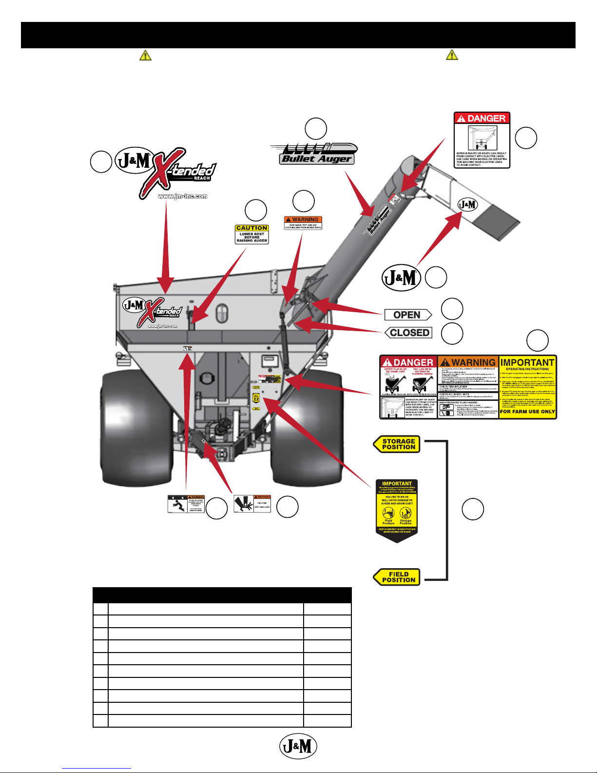
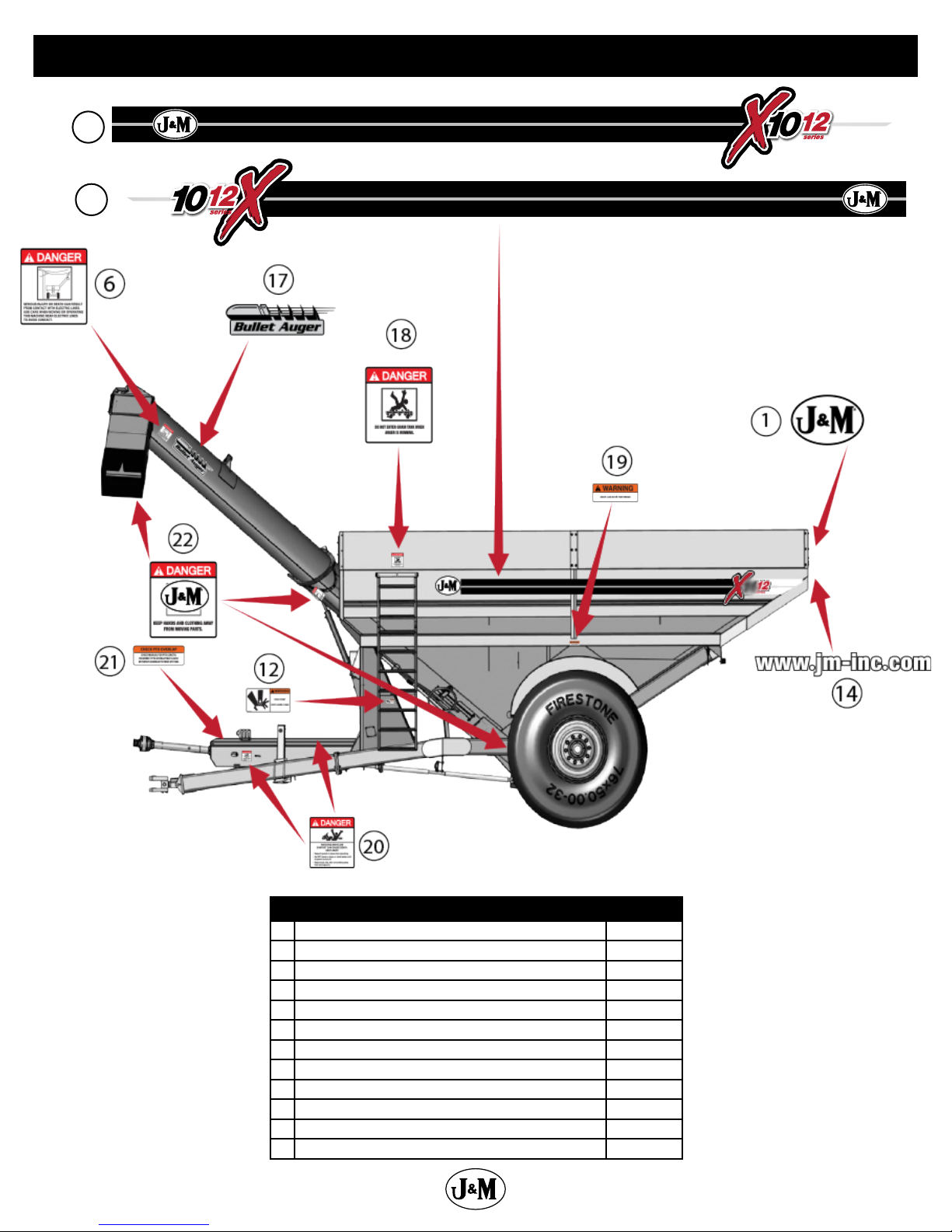
Decals
ATTENTION! BECOME ALERT! YOUR SAFETY IS INVOLVED!
Replace Immediately If Damaged or Missing
2
3
4
5
7
8
9
6
10
Description Part No.
1 J&M Oval Decal (Large) 9-1/2” x 15” JM0015151
2 X-Tended Reach Decal JM0037663
3 Caution Lower Rest Decal JM0037662
4 Warning, Keep Hands Away Decal JM0018039
5 Bullet Auger Decal JM0037664
6 Danger, Electric Lines Decal JM0015099
7 J&M Oval Decal (Medium) 5-1/2” x 8-1/2” JM0010179
8 Open Decal JM0025433
9 Closed Decal JM0025434
10 Danger Warning Important Decal JM0037665
10
13
12
11
Page 11
16
15
Decals
Description Part No.
11 Field Position/Storage Position Decal JM0037661
12 Warning, Pinch Point Decal JM0014994
13 Warning, Falling Or Lowering Decal JM0014992
14 www.jm-inc.com Decal JM0019239
15 Opposite Auger Side Stripe Kit Specify
16 Auger Side Stripe Kit Specify
17 Bullet Auger Decal AS JM0041315
18 Danger, Do Not Enter Grain Tank Decal JM0018033
19 Warning, Keep Lug Nuts Tightened Decal 1-5/8” x 4” JM0010150
20 Danger, Rotating Driveline Decal JM0018036
21 Check PTO Overlap Decal JM0025435
22 Danger, Keep Hands and Clothing Away Decal JM0018035
11
Page 12

Safety Rules
ATTENTION! BECOME ALERT! YOUR SAFETY IS INVOLVED!
Safety is a primary concern in the design and manufacture of our products. Unfortunately, our eorts to provide safe equipment
can be erased by an operator’s single careless act. In addition, hazard control and accident prevention are dependent upon the
awareness, concern, judgment, and proper training of personnel involved in the operation, transport, maintenance and storage of
equipment.
Make certain that the operator(s), prior to operating is instructed in safe and proper use and reviews and understands the manual(s)
pertaining to this machine. Also make certain that the operator(s) reviews and understands the operator’s manual of the tractor
prior to hooking up or operating the grain cart.
Read this manual before you operate this machine. If you do not understand any part of this manual, or need more information,
contact the manufacturer or your authorized dealer.
SAFETY
Understand that your safety and the safety of other persons is measured by how you service and operate this machine. Know the
positions and functions of all controls before you try to operate them. Make sure to check all controls in a safe area before starting
your work.
The safety information given in this manual does not replace safety codes, federal, state or local laws. Make certain your machine
has the proper equipment as designated by local laws and regulations.
A frequent cause of personal injury or death is from persons falling o equipment and being run over. Do not permit persons to
ride on this machine.
Travel speeds should be such that complete control and machine stability is maintained at all times. Where possible, avoid operating
near ditches, embankments and holes. Reduce speed when turning, crossing slopes and rough, slick or muddy surfaces.
Collision of high speed road trac and slow moving machines can cause personal injury or death. On roads, use asher lights
according to local laws. Keep slow-moving-vehicle emblem visible. Pull over to let faster trac pass.
Hydraulic oil leaking under pressure can penetrate skin and cause infection or other injury. To prevent personal injury,
• Relieve all pressure, before disconnecting uid lines,
• Before applying pressure, make sure all connections are tight and components are in good condition,
• Never use your hand to check for suspected leaks under pressure. Use a piece of cardboard or wood for this purpose.
• If injured by leaking uid, see your doctor immediately.
When transporting the grain cart, always keep the auger in the stow position.
Use care when moving of operating the grain cart near electric lines as serious injury or death can result from contact.
Never adjust, service, clean, or lubricate the grain cart until all power is shut o. Keep all safety shields in place. Keep hands, feet,
hair and clothing away from moving parts while the grain cart is in operation.
The service ladder is for service work only. If you must climb into the grain tank, be certain that all power is shut o and then use
extreme caution when climbing into the grain cart.
Make sure that everyone is clear of equipment before applying power or moving the machine.
Make sure that the grain cart is fastened securely to the tractor by using a high strength hitch pin, clip and safety chains. Make sure
that the grain cart hitch properly matches the hitch type of the tractor. Use a single prong (spade) grain cart hitch with a double
prong (clevis) tractor hitch. Use a double prong (clevis) grain cart hitch with a single prong (spade) tractor hitch.
Before lling the grain cart, make certain that no one is inside the grain tank. Never allow children or anyone in, near, or on the
grain cart during transport or during loading and unloading of grain. Be aware that moving grain is dangerous and can cause
entrapment, resulting in severe injury or death by suocation.
Never operate the auger system with anyone inside the grain tank. Hands, feet, hair and clothing can t through the openings in
and around the grate. Contact with the auger can cause severe injury or death. Make certain that all power is shut o before service
work is performed.
Before unhooking the grain cart from the tractor, be sure the jack stand is properly mounted and in place and the wheels are
properly blocked to prevent the cart from moving.
12
Page 13

Initial Operation and Maintenance
WARNING
BE CERTAIN THAT ALL POWER IS SHUT OFF BEFORE SERVICING THE GRAIN CART.
Before the grain cart is put into service:
Have the safety instructions been read and clearly understood by the operator(s) of this machine?
Has the gearbox been properly lled with SAE 80W-90 gearbox lubricant?
Have all nuts, bolts, bearings and braces been properly fastened?
Has the PTO been checked for proper overlap?
IMPORTANT: Has the slip clutch on the PTO been serviced? If the slip clutch is left unchecked, damages to the power-take-o
and drive shaft may result. Before using the grain cart, loosen the bolts around the slip clutch. Make sure the friction plates turn
free of each other and are not corroded together. Re-tighten the tension bolts. Run the auger system EMPTY and check for proper
engagement of the slip clutch.
CHECK PTO OVERLAP LENGTH. Overlap length may vary depending on the tractor model and hitch setting. Try to obtain the
greatest possible overlap without bottoming out in the extreme operating conditions. Too much overlap may cause the PTO to
bottom out and damage the driveline. Not enough overlap may cause the PTO front and back halves to separate. From the fully
compressed (shortest) length the PTO should be telescoped (extended) between 10” and 22”. Dierent PTO lengths may need
to be purchased to accommodate your terrain. A 4” shorter or a 10” longer PTO can be ordered through your dealer from J&M
Manufacturing.
GREASE BEARINGS: Are all bearings on the drive line properly greased? Are all set screws in the bearings and U-joints tight? Has
the power-take-o shaft been properly greased at all points including the cross bearings? Has the universal joint at the gearbox
been greased? Have all grease points at the auger hinge area, including the hanger bushing assembly been greased?
TIRE PRESSURE: Are the tires properly inated? The following is to be used as a general guide for tire ination for cyclic use.
Figures can vary depending on specic brand of tire used. It is important that tires are inspected before and after the unit is
loaded. The tire should stand up with no side wall buckling or distress as the tire rolls. Do Not Exceed The Tire Pressure
Indicated Below:
Tire psi
900/60R32 Lug Tires (Firestone) (176LI) (for 30x32-10 Hole Wheels) (136” c/c) 41
900/60R32 Lug Tires (Alliance) (176 LI) (for 30x32-10 Hole Wheels) (136” c/c) 66
35.5x32 Diamond Tires-20 ply (Firestone) (for 31x32-10 Hole Wheels) 26
1050/50R32 Lug Tires (Alliance) (185 LI) (for 32x36-10 Hole Wheels) 56
480/80R42 Lug Tires (Firestone) (154 LI) (for16x42-10 Hole Wheels) 35
480/80R42 Lug Tires (Alliance) (169 LI) (for16x42-10 Hole Wheels) 64
IF520/85R42 Lug Tires (Firestone) (169 LI) (for 18x42-10 Hole Wheels) 44
520/85R42 Lug Tires (Alliance) (169 LI) (for 18x42-10 Hole Wheels) 50
IF1250/50R32 Lug Tires (Firestone) (188 LI) (for 44x32-10 Hole Wheels) 23
13
Page 14
Operating Instructions
VERY IMPORTANT: Under no circumstance is it recommended to tow a loaded grain cart in excess of 8 mph.
WHEEL NUTS: Are the wheel nuts properly fastened? Torque to 640 Ft.-Lbs. for standard 22mm wheel studs and nuts. Torque to
400 Ft.-Lbs. for 3/4” wheel studs and nuts. Wheel studs and nuts should be checked after each load during initial operation
of the cart and then after every 10 hours of use. Failure to do so may damage wheel studs and nuts. Once the seats are
damaged, it will become impossible to keep the lug nuts tight.
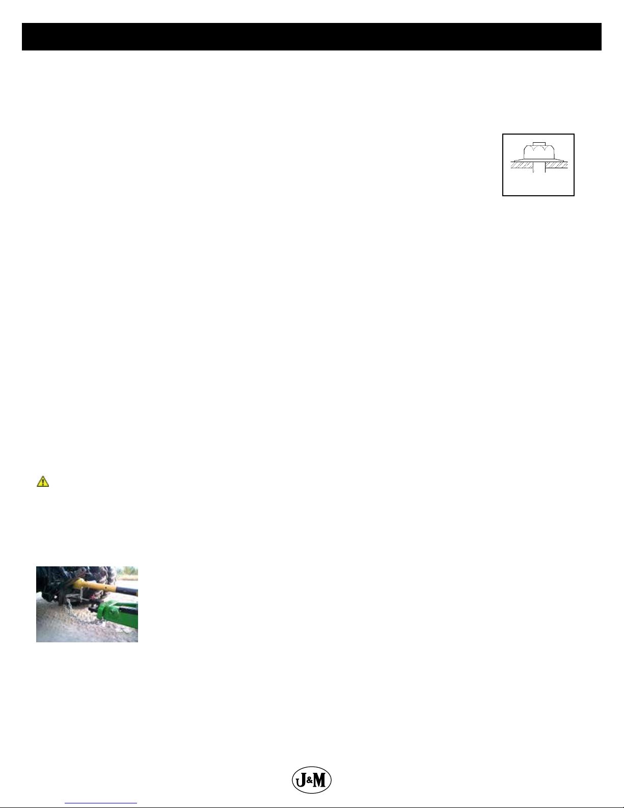
The drawing shows the proper way to mount the wheels using Budd-type nuts. The wheels supplied with
your grain cart have straight holes and the Budd nuts will be mounted according to Figure 1. Wheels that
are improperly installed on the grain cart, resulting in product failure, will nullify warranty and shift the
burden of liability to the owner/operator. We recommend you inspect your wheel nuts to make sure they
are properly installed. Also, check the wheel nuts on a regular basis to ensure they are tight.
LIGHTING AND SAFETY DECALS: Are the rear, amber extremity lights properly positioned? Extend the lights within 16” (40,6cm)
of the left and right extremities of the grain cart. Is an SMV Emblem attached to the rear of the grain cart?
Are the lights working properly? Are all lights and reective decals clean, visible and properly placed?
BE CERTAIN THAT ALL POWER IS SHUT OFF WHEN HOOKING UP TO TRACTOR OR CONNECTING HYDRAULIC LINES TO
TRACTOR.
Preparing the Grain Cart for Use: Model 1012 grain carts require a 225+ HP Tractor.
IMPORTANT: Do NOT pull a loaded grain cart on highway. For incidental highway travel, observe the section below.
Tow Loads Safely
Stopping distance increases with speed and weight of towed loads, and on slopes. Towed loads with or without brakes that are too
heavy for the tractor or are towed too fast can cause loss of control. Consider the total weight of the equipment and its load.
Observe these recommended maximum road speeds, or local speed limits which may be lower.
Road Travel (grain cart empty): Do not travel more than 32 km/hr (20 mph) and do not tow loads more than 1.5 times the
pulling unit’s weight.
Ensure the load does not exceed the recommended weight ratio. Use additional caution when towing loads under adverse surface
conditions, when turning, and on inclines.
WARNING: For greater stability on uneven or steep terrain, position non-scale wheel spindles at the furthest out setting.
Figure 1
IMPORTANT:
1) Connect grain cart hitch to tractor drawbar using a good quality hitch pin. Attach the safety chain to the tractor and through one
chain loop provided on either side of the grain cart frame as shown. Make sure the grain cart hitch properly matches the hitch of
the tractor. Use a single prong (spade) grain cart hitch with a tractor double prong (clevis) hitch. Use a double prong (clevis) grain
cart hitch with a single prong (spade) tractor hitch.
Safety Chain User Instruction
a) Secure the safety chain by looping it around each side of the grain cart as shown and
connecting to the towing machine’s attaching bar.
b) Do Not allow any more slack than necessary for articulation.
c) Do Not use any intermediate support as the attaching point.
d) Store the safety chain by securing it around the main axle A-frame of the grain cart.
e) Replace the safety chain if one or more links or end ttings are broken, stretched or otherwise
damaged or deformed.
2) Attach the power-take-o shaft to the tractor. The PTO must have at least 10” of engagement. Check tractor drawbar for clearance
and length and adjust if necessary. Make sure the PTO does not bottom out when making sharp turns as it may bend the drive
shaft.
3) Make sure the jack stand is removed from the lower support position before the cart is moved. Never use the jack to support
a loaded grain cart.
4) Be sure that no debris or foreign objects are in the grain cart.
5) Attach the hydraulic lines to the tractor. Two hydraulic lines (green band) operate the inside gate mechanism. Connect these
Continues on next page.
14
Page 15
Operating Instructions (Continued)
lines to one service outlet on the tractor. Two hydraulic lines (yellow band) operate the folding mechanism of the auger. Connect
these lines to a second service outlet on the tractor. The remaining two hydraulic lines (red band) operate the hydraulic ow control
spout located at the end of the upper auger. Connect these lines to a third service outlet on the tractor. Make sure the air is bled
from the hydraulic cylinders and hoses.
6) Run the auger system EMPTY before loading grain into the tank for actual use. Make certain that the slip clutch is operating and
that the upper and lower augers are properly engaged.
7) Connect the lighting 7-prong connector end on the main wiring harness to the tractor electrical outlet. Make sure that all asher
and turn indicator lights are working properly before incidental highway travel.
CAUTION
• Do NOT operate the grain cart before reading and understanding the Operator’s Manual and ALL danger, warning and
caution signs.
• Be sure that a Slow-Moving-Vehicle emblem is attached to the rear of the grain cart.
• Never exceed 1,000 rpm on the PTO and driveline system.
• Never fold or extend the auger until the PTO has come to a complete stop.
• Never ll the grain cart unless the gate indicator is in the closed position.
• Never allow foreign object (shovels, etc.) to be placed inside the grain cart.
• Never engage the lugs and drive dogs on the augers when the system is moving at a high rate of speed.
• Never perform maintenance work or service the grain cart with the tractor running.
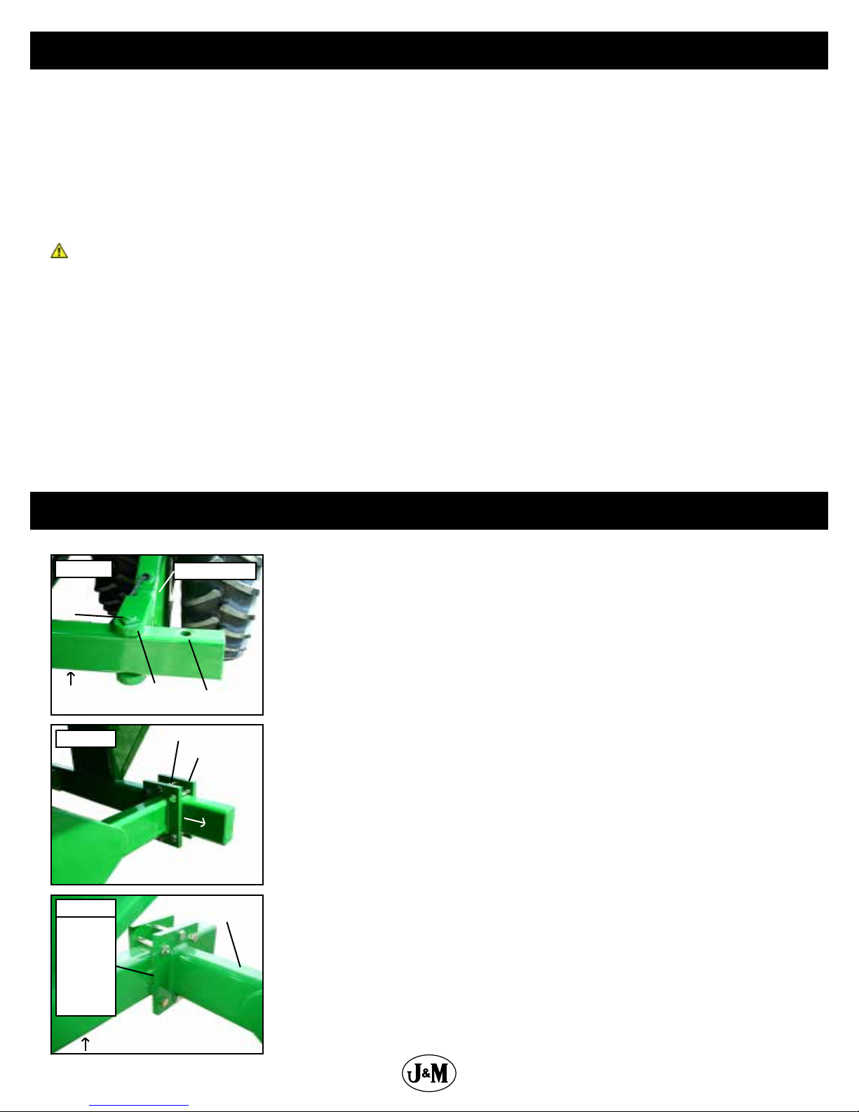
Figure A
1 3/4” x
13 1/2”
Bolt
JACK
Figure B
Frame
Weldment
Figure C
For 36” row
spacing,
place
Frame
Weldment
9” from
edge of
Stop.
Adjusting Row Spacing for Walking Tandem Duals
Frame Weldment
30” Row
Spacing
1” x 7 1/2” Bolt
Slide Frame Weldment out
9” for 36” Row Spacing
36” Row
Spacing
Clamp Plate
Frame Weldment
for Dual Wheels
1) Securely position jacks under the frame of the grain cart as shown in Figures A and C.
2) Loosen the rear of the Frame Weldment by removing the 1” x 7 1/2” Gr 8 Bolts and
Clamp Plate.
3) Remove the 1 3/4” x 13 1/2” Bolt and Jam Nut from the front of the Frame Weldment.
4) Slide the Frame Weldment out to the bolt location for 36” row spacings as shown
in Figure A and secure using the 1 3/4” x 13 1/2” bolt and jam nut. If the grain cart is
equipped with an electronic scale system, be sure not to damage the electronic cord
when moving the Frame Weldment.
5) Swing the Frame Weldment outward. Switch the tire location by removing both
tires and remounting each tire to the hub on the opposite side of the weldment. The
tire originally on the outside of the weldment will now be located on the inside of
the weldment and vice versa. (The valve stems for 36” row spacing should be facing
toward the Frame Weldment, or toward each other.) Be sure to keep the tire tread
positioned in the same direction as before.
6) After the wheels have been tightened to the hubs, swing the Frame Weldment until
the new clamping location is 9” from the original 30” row spacing stop.
7) Tighten the rear of the Frame Weldment to the grain cart frame using the six 1” x 7
1/2” Gr 8 Bolts, Hex Nuts and Clamp Plate.
8) Torque all bolts to specications and Repeat on Other Side.
JACK
15
Page 16

Lubrication Service Schedule
IMPORTANT: Your grain cart has grease ttings at all critical points. These should be serviced before the grain cart is put into
operation.
WARNING
BE CERTAIN THAT ALL POWER IS SHUT OFF BEFORE SERVICING THE GRAIN CART
PTO & DRIVELINE: The grease ttings on the PTO should be serviced after every 8 hours of use. Service the grease ttings on each
of the drive bearings and also the universal joint after every 8 hours of use.
AUGER FOLDING MECHANISM: One grease tting is located on the pivot pin of the folding auger. This tting should be serviced
after every 8 hours of use. Service the grease tting on the hanger bushing assembly (top end of the lower auger assembly) after
every 8 hours of use or as needed.
SPRING LOADED UPPER AUGER BEARING: Service the grease tting on the upper auger bearing (located at the top end of the
upper auger assembly) after every 8 hours of use. Lubricate the springs and retaining bolts on the bearing before prolonged
storage of the grain cart.
Gearbox Lubricant
Model Ounces Input Sha Output Sha
1012 96 1-3/4” 2”
Pivot Pin Once Annually
Roll Tarp U-Joint Once Annually
Upper Auger Flighting Every 8hrs of use
Driveline Every 8hrs of use
GEARBOX: Gearbox lubricant has been added to the gearbox during nal assembly. Recheck the lubricant level before initial operation
of the grain cart, then periodically according to use. The uid level should rest at the inspection plug, pictured in blue below. When
lled to the proper level, the gearbox should have 96 ounces of
SAE 80W-90 lubricant. Change the oil annually before use.
16
Page 17

Routine Maintenance
WARNING
BE CERTAIN ALL POWER IS SHUT OFF WHEN SERVICING THE GRAIN CART
• Repack the bearings in the hub assembly once a year or as needed. Use a good quality LS EP2 Severe Duty, High Shock Load,
Lithium based Grease. Also check the seal for wear and replace if necessary.
• Check the grain cart periodically for cracks in welds and for other structural damage. Have cracked welds xed immediately.
Failure to do so could result in extensive damage to the grain cart and greatly reduce the life of the cart.
• Lubricate the slides on the clean-out door.
• Check all hydraulic hoses for wear and replace as necessary.
• Make sure all tires are properly inated. See INITIAL OPERATION AND MAINTENANCE in the Owner’s Manual for recommended
instructions for tire pressure. It is important that tires are inspected before and after unit loaded.
• Check PTO for wear of plates in the slip clutch. Replace if needed.
• Make sure that all guards and shields are in place before operating the grain cart.
Troubleshooting
WARNING
MAKE SURE THAT ALL POWER IS SHUT OFF BEFORE SERVICING THE GRAIN CART. MAINTENANCE AND
REPAIR SERVICE WORK TO BE PERFORMED BY QUALIFIED SERVICE PERSONNEL ONLY.
Trouble Possible Cause Possible Remedy
Dirt in restrictor Remove restrictor ttings from outside hydraulic cylinder and clean out dirt
Faulty check valve Replace check valve
Auger will not return to down
position or move from stow
position
Hanger bushing assembly at
the top of the lower auger
ighting is hot
Excessive vibration
Grain ow stoppage
Auger tube is breaking away
from the grain cart at the
hinge area or the ram in the
hydraulic folding cylinder is
bent
Flip-up auger rest not
ipping over center
Upper ighting and lower ighting
are locked together
Feed gate open Close the feed gate
Lock and Load not operating
correctly
Top of the hanger bushing
assembly is rubbing against the
drive dog
Auger ighting or shaft is bent Straighten or replace auger ighting
Drive shaft is bent Replace or straighten drive shaft
Bolt sheared in drive dog Replace bolt in drive dog. Engage upper and lower ighting at a slow rate of
Folding auger before complete stop Upper and lower ightings are disengaging before auger comes to a complete
PTO key sheared Replace key and tighten set screw
Upper auger is extended in the
upright position while traveling in
the eld
Cable has loosened With auger in eld position, tighten cable to the handle.
Bearing on top of upper auger ighting needs adjusting. When the auger is
in the engaged position, there must be 1/8” (0,32cm) gap between bottom of
top bearing and top of upper tube housing (SEE ADJUSTING THE UPPER AUGER
FLIGHTING)
Make sure the limit switch on the feed gate indicator assembly is functioning
properly
Loosen the two bolts and re-adjust the position of the hanger bushing assembly.
Re-tighten bolts
Remove the lower ighting assembly and place a shim between the spline
coupler and the gearbox
speed. (Drive dogs and lugs are being engaged too fast.)
stop. Replace bolt in the drive dog. Never engage or disengage the upper and
lower ightings until the augers come to a complete stop.
Repair or place folding cylinder if necessary. Remember to lower auger to the
eld position after unloading.
17
Page 18

Adjusting the Lower Flighting
WARNING
MAKE SURE THAT ALL POWER IS SHUT OFF BEFORE ADJUSTING THE FLIGHTING ASSEMBLY.
If the drive-dog and hanger assembly are becoming excessively hot during unloading, the lower ighting and/or hanger may need
adjusting. The hanger bushing assembly has elongated holes where it attaches to the outer tube assembly. Loosen the two 3/8”
bolts on the hanger bushing assembly. Adjust the hanger either up or down and vertically center it between the ighting and drive
dog. Re-tighten the bolts. Make certain that the ighting center and drive-dogs do not rub the hanger bushing assembly, causing
them to become hot.
If the hanger can no longer be adjusted by moving it up or down on the elongated holes, both the hanger bushing assembly and
the lower ighting will have to be removed. See instructions on pg. 36 for ighting removal. After removing them from the tube
assembly, place a shim [between 1/8” (0,32cm) to 3/16” (0,48cm) thick] where the gearbox and the spline coupler (welded to the
lower ighting). Replace the lower ighting and reattach the hanger to the tube assembly. Readjust the hanger assembly. NOTE:
The bottom of the lower ighting is not attached to the gearbox with any bolts or set screws but may be ‘frozen’ fast. Be careful
when removing the lower ighting from the gearbox. For easier removal of the lower ighting, keep the gearbox at the bottom
intact, remove the 2 3/8” bolts from the hanger bushing assembly and pull the lower ighting o of the gearbox.
After adjusting the lower ighting, move the upper auger to the unload position and check the upper ighting for readjustment.
Adjusting the Upper Flighting
WARNING
MAKE SURE ALL POWER IS SHUT OFF BEFORE ADJUSTING THE FLIGHTING ASSEMBLY
If the upper and lower augers to do not properly separate during the unfolding sequence, the upper ighting may need adjusting.
Before making adjustment to the upper ighting, check to see if the lugs and drive dogs on the auger assemblies are locking
together. If they are not locked together, check to see if dirt is in the restrictor or if a faulty check valve on the hydraulic cylinder
used to raise and lower the upper auger assembly may be causing the problem. If dirt is in the restrictor, see “Removing Dirt From
Restrictors On Hydraulic Cylinders” below.
Fold the upper tube assembly into the upright position. Position the upper ighting in the engaged position with the lower ighting.
Locate the four-hole ange bearing on the top of the upper auger tube housing. With the upper ighting in the engaged position,
check the spacing between the upper bearing and the upper tube housing. There must be an 1/8” (0,32cm) space between the
base of the four-hole ange bearing and the upper tube housing. If there is NOT a space between the bearing and the upper tube
housing, or if there is more than 1/8” (0,32cm) space, the upper ighting will need to be adjusted. To adjust the upper ighting,
loosen the 1 1/4” hex nuts both above and below the four-hole ange bearing. Move the 1 1/4” hex nuts up or down the threaded
shaft on the top of the auger ighting shaft until the bearing moves to approximately 1/8” (0,32cm) above the base of the upper
tube housing. When the four-hole ange bearing is properly located, tighten both 1 1/4” hex nuts together to secure the bearing
position.
If the upper and lower ighting still does not separate properly during the folding sequence, a small bevel may need to be removed
from the inside of the lugs where they engage the drive dogs on the auger assemblies. Grind approximately 1/8” (0,32cm) from the
corner of the lugs where they touch against the drive dogs.
18
Page 19

Removing Dirt from the Restrictors on the Hydraulic Cylinder
WARNING
MAKE SURE THAT ALL POWER IS SHUT OFF AND THE UPPER AUGER TUBE IS IN THE DOWN POSITION BEFORE REMOVING
THE RESTRICTORS
Remove restrictors from the 90 degree street elbow on the hydraulic cylinder. Remove dirt from the tting to allow hydraulic oil to
ow through the restrictor. Reattach the restrictor to the street elbow. Use Teon sealant tape or equivalent on the threads of the
restrictor before re-attaching.
If the restrictor continues to plug with dirt, replace the restrictor or lter the hydraulic oil in your system.
Storage Preparation
IMPORTANT: When the grain cart is not going to be used for a period of time, store the cart in a dry, protected place. Leaving your
grain cart outside, open to the weather will shorten its life.
Follow the procedure below when your grain cart is placed in storage for periods up to six months.
1. Cover electronic monitor (if equipped) with plastic before washing the grain cart. Wash or clean and completely lubricate the
grain cart. See the lubrication service section in this manual.
2. Remove all grain from inside the grain tank, auger tube assemblies, and at the clean-out door.
3. Check the gearbox oil and replace with new SAE 80W-90 gearbox lubricant or equivalent if necessary.
4. Touch up areas where paint may have worn away. Use a good quality primer paint, especially before re-applying graphite paint
to the interior slopes of the grain tank.
5. Retract all hydraulic cylinders to prevent the piston rods from rusting.
6. Clean the tires before storage. Inate the tires at regular intervals.
7. Open the clean-out door at the base of the grain tank.
Removing from Storage
• Check the gearbox to make sure it has the appropriate amount of oil.
• Inate the tires to the correct operating pressure.
• Close the clean out door at the base of the grain tank.
• Make sure all safety shields are in the proper position.
19
Page 20

Repair Parts List and Diagrams
When performing maintenance work, wear sturdy, rough-soled work shoes and protective equipment for eyes, hair, hands, hearing
and head. Follow the Operator’s Manual instructions to ensure safe and proper maintenance and repair.
Your local, authorized dealer can supply genuine replacement parts. Substitute parts may not meet original equipment specications
and may be dangerous.
WARNING
MAKE SURE ALL POWER IS SHUT OFF BEFORE PERFORMING ANY MAINTENANCE OR REPAIR WORK.
Wheel Rims for Single Wheel Grain Carts
Description
30x32-10 Hole Wheel Rims
31x32-10 Hole Wheel Rims
32x36-10 Hole Wheel Rims
44x32-10 Hole Wheel Rims
Tires for Single Wheel Grain Carts
Description
900/60R32 Lug Tires (Firestone) (176LI) (for 30x32-10 Hole Wheels) (136” c/c)
900/60R32 Lug Tires (Alliance) (176 LI) (for 30x32-10 Hole Wheels) (136” c/c)
35.5x32 Diamond Tires-20 ply (Firestone) (for 31x32-10 Hole Wheels)
1050/50R32 Lug Tires (Alliance) (185 LI) (for 32x36-10 Hole Wheels)
IF1250/50R32 Lug Tires (Firestone) (188 LI) (for 44x32-10 Hole Wheels)
Wheel Rims for Walking Tandem Dual Wheel Grain Carts
Description
16x42-10 Hole Wheel Rims
18x42-10 Hole Wheel Rims
Tires for Walking Tandem Dual Wheel Grain Carts
Description
480/80R42 Lug Tires (Firestone) (154 LI) (for16x42-10 Hole Wheels)
480/80R42 Lug Tires (Alliance) (169 LI) (for16x42-10 Hole Wheels)
IF520/85R42 Lug Tires (Firestone) (169 LI) (for 18x42-10 Hole Wheels)
520/85R42 Lug Tires (Alliance) (169 LI) (for 18x42-10 Hole Wheels)
20
Page 21

Hub & Spindle Assembly W-891 (Single Wheels)
Torque Values
22mm Studs 640 Ft.-Lbs.
Description Part No.
1 Hub and Spindle Assembly 4-1/2” x 20-1/4” Spindle with 22mm Studs (HSA-1000) JM0019942
2 1”-8 Gr5 Z Centerlock Hex Nut JM0002149
3 1”-8 x 7” Gr5 Z Hex Bolt JM0016689
4 Spindle, 4 1/2” x 20 1/4” (281900S) JM0019937
5 Seal (4-1/4” ID, 6” OD) (CR-43771) JM0018955
6 Large Bearing (HM218248) JM0018849
7 Large Race (HM218210) JM0018848
8 891 Hub with Races, 22mm Studs, and Nuts (13.19 bolt circle) (11.13 pilot) (W-891) JM0021227
9 Wheel Stud (22mm x 90mm) (22-MMS) JM0019178
10 22mm Lug Nut with Washer (22-MMNW) JM0019192
11 Small Race (HM212011) JM0018854
12 Small Bearing (HM212049) JM0018852
13 2-1/8” ID, 3-3/4” OD Flat Washer (3/16”) JM0015900
14 2”-12 Gr5 Z Castle Hex Nut (912973) JM0015899
15 3/8” x 2-3/4” Z Roll Pin (905945) JM0018956
16 Dust Cap 6-1/4” OD (for W-881 & W-891 Hub)(909921) JM0018954
17 1/4”-20 x 1” Gr5 Z Hex Bolt JM0002095
18 891 Hub with Races, 22mm Studs, Nuts, Seal, Bearings, and Dust Cap JM0048171
21
Page 22

Hub & Spindle Assembly W-881 (Walking Tandem Dual Wheels)
Torque Values
3/4" Studs 400 Ft.-Lbs.
Description Part No.
1 Hub and Spindle Assembly Complete 20-1/4” (3/4” Studs) (HSA-650D) (Walking Tandem Duals)(FAA) JM0019940
1 W-881 Hub and 4-1/2” Weigh-Tronix Spindle Assembly Complete 20-1/4” (3/4” Studs) (Walking Tandem Duals)(FAA) JM0019975
2 1”-8 Gr5 Z Centerlock Hex Nut JM0002149
3 1”-8 x 7” Gr5 Z Hex Bolt JM0016689
4 Spindle, 4-1/2” x 20-1/4” (281900S) JM0019937
4 4-1/2” Weigh-Tronix Weigh Spindle (AWT27-500002) (450WTS) JM0019970
5 Seal (3-3/4” ID, 6” OD) for Hub with Scales (37605SA) JM0021456
5 Seal (4-1/4” ID, 6” OD) (CR-43771) JM0018955
6 Large Bearing (HM218248) JM0018849
7 Large Race (HM218210) JM0018848
8 Hub with large and small races, 3/4” Studs & Nuts (11.13 pilot)(W-881) JM0020510
9 Wheel Stud (3/4”-16 x 1-3/4”) 913564 JM0018957
10 Wheel Nut 3/4”-16 JM0018958
11 Small Race (HM212011) JM0018854
12 Small Bearing (HM212049) JM0018852
13 2-1/8” ID, 3-3/4” OD Flat Washer (3/16”) JM0015900
14 2”-12 Gr5 Z Castle Hex Nut (912973) JM0015899
15 3/8” x 2-3/4” Z Roll Pin (905945) JM0018956
16 Dust Cap 6-1/4” OD (for W-881 & W-891 Hub)(909921) JM0018954
17 1/4”-20 x 1” Gr5 Z Hex Bolt JM0002095
18 W-881 Hub 10 on 13.19 with Races Lugs, 3/4” Studs, Seals, Bearings, Dust Cap JM0048156
22
Page 23

Power Take-O (PTO) Shaft Assembly
Description Part No.
1 Back Half Weasler PTO (1-3/4”) (Auto Clutch) JM0018513
1 Back Half Weasler PTO (1-3/4”) (Auto Clutch) (XL) 5 “ Longer JM0030331
2 Front Half Weasler PTO (1-3/4”) (Auto Clutch) JM0018514
2 Front Half Weasler PTO (1-3/4”) (Auto Clutch) (XL) 5 “ Longer JM0030330
2 Front Half Weasler PTO (1-3/8”) (Auto Clutch) JM0024367
2 Front Half Weasler PTO (1-3/8”) (Auto Clutch) (XL) 5 “ Longer JM0030640
3 55E Cross Kit (Auto Clutch PTO) (1-3/4”) JM0018449
4 Auto Clutch (1-3/4” PTO) (Weasler) JM0018500
5 Yoke, Tube & Sleeve (1-3/4” PTO) (Weasler) JM0018519
5 Yoke, Tube & Sleeve (XL) Weasler JM0031647
6 Yoke & Shaft Assembly (1-3/4” PTO) (Weasler) JM0018520
6 Yoke & Shaft Assembly (XL) Weasler JM0031648
7 Spring Lock Yoke (1-3/4” PTO) (Weasler) JM0018506
7 Spring Lock Yoke (1-3/8” PTO) (Weasler) JM0024353
8 Weasler Auto Clutch Front Guard (30-3/4”) JM0018518
8 Weasler XL Auto Clutch Front Guard (36”) JM0030642
8 Weasler Auto Clutch Back Guard (27-3/4”) JM0018517
8 Weasler XL Auto Clutch Back Guard (34”) JM0030645
9 Complete 1-3/4” Weasler PTO (Auto Clutch) JM0018443
9 Complete 1-3/4” Weasler PTO (Auto Clutch) (XL) 10 “ Longer JM0030332
9 Complete 1-3/8” Weasler PTO (Auto Clutch) JM0024333
9 Complete 1-3/8” Weasler PTO (Auto Clutch) (XL) 10 “ Longer JM0030641
23
Page 24

130 Degree Gearbox Assembly (Weasler)
2
Takes 3 Quart (96 Ounces) ofSAE 80W-90
Gearbox Lubricant.
3
4
1
8 9 1110
5
6
7
11 910 1312
24
3
Page 25

130 Degree Gearbox Assembly (Weasler)
14 15 16 17 18
Description Part No.
1 1/2”-14 NPT Pipe Plug for Weasler Gearbox (72-20007) JM0025068
2 1/2” NPT Bushing 1/8” NPT Relief Plug (72-20011) JM0025067
3 2” Output Shaft & Gear Assembly for Weasler Gearbox (74-60125) JM0025058
4 3/8”-16 UNC x 2-1/2” Gr5 Cap Screw for Weasler Gearbox (72-0002) JM0025069
5 Housing Set For Weasler Gearbox (70-001114) JM0025053
6 1-3/4” Input Shaft & Gear Assembly for Weasler Gearbox (74-60123) JM0025057
7 Gearbox Eterior Dust Seal 1-3/4” ID JM0049020
8 End Cap Seal (3-3/16” x 5/16”) for Weasler Gearbox (71-40079) JM0025063
9 Spacer for Weasler Gearbox (71-50072) JM0025066
10 Bearing Cup (3720) for Weasler Gearbox (71-20033) JM0025056
11 Bearing Cone (3780) for Weasler Gearbox (71-20044) JM0025055
12 Gear - 34 Teeth (71-06135) JM0046061
13 Seal (2 x 3.196 x 0.4333) for Weasler Gearbox (71-40080) JM0025062
14 End Cap Seal (2” x 9/64”) for Weasler gearbox (71-40016) JM0025060
15 Spacer for Weasler Gearbox (71-50160) JM0025064
16 Bearing and Race Set (32210) for Weasler Gearbox (71-20017) JM0025054
17 Gear - 17 Teeth (71-06134) JM0046059
18 Spacer for Weasler Gearbox (71-50161) JM0025065
19 Seal (1-3/4” x 2-23/32” x 33/64”) for Weasler gearbox (71-40052) JM0025061
20 130° Gearbox (1-3/4” Input, 2” Output) (Weasler)(130-22W) JM0018677
1916
6
25
Page 26

Hitch Assembly
Description Part No.
1 1”-8 x 5-1/2” Gr5 Z Hex Bolt JM0002110
2 2-7/8” x 16-3/4” Non-Scale Hitch Bar JM0025227
3 1”-8 x 7” Gr8 YZ Hex Bolt JM0042653
4 Cast Iron Spade 2-1/4” Pin Hole JM0020529
5 Cast Iron Clevis (Bolt-On) 2-1/4” Pin Hole JM0020527
6 3/4”-16 x 2-1/2” Gr8 YZ Fine Thread Hex Bolt JM0015323
7 2-7/8” Digi-Star Weigh Bar, 1” Pin Hole (278WB-T1) JM0000355
8 1-1/4”-7 Gr5 Z Nylon Locking Hex Jam Nut JM0027201
9 1”-8 Gr5 Z Centerlock Hex Nut JM0002149
10 40k Lb Safety Chain JM0029261
11 1-1/4”-7 x 4” Gr8 Z Hex Bolt JM0026073
12 Cast Iron Clevis Hitch Assembly JM0020537
26
Page 27

Driveline Assembly
Description Part No.
1 3 Keyed LF Hydraulic Hose Holder JM0021437
2 Hydraulic Hose Shield 82-1/2” (812, 1012, 1112, 1122, 1222) JM0036484
3 PTO Shield 85-1/4” (812, 1012, 1112, 1122, 1222) JM0036430
4 PVC (Cut to length) JM0027151
5 164-1/2” x 1-3/4” Drive Shaft (1012, 1112, 1122, 1222, 2431) JM0026002
6 Jack Stand Assembly w/ Plate (10,000 lbs.) JM0020936
7 5/8”-11 Gr5 Z Centerlock Hex Nut JM0002146
8 Square U-Bolt 7-1/8” Inside Width x 9” Length, 5/8”-11TH JM0024199
9 3/8”-16 x 1/2” Hex Head Set Screw JM0019044
10 44 Series U-Joint (252288) - Weasler 44063-A1 JM0017957
11 5/8”-11 x 3” Gr5 Z Hex Bolt JM0002105
12 3/8”-16 Gr5 Z SF Hex Nut JM0002152
13 2” Output Shaft Gearbox Spline Washer (22”) (3” OD) JM0020638
14 1/2” Gr2 Z Lock Washer JM0019021
15 3/8”-16 x 1” Gr5 Z SF Hex Bolt JM0002092
16 1/2”-13 x 1-1/2” Gr5 Z Hex Bolt JM0002100
17 U-Joint Shield JM0012698
18 Cross Kit (U-Joint) (44R) (CK-44R) JM0017958
19 3/8” x 1-1/2” Half Moon Key JM0018772
20 5/8”-11 x 1-3/4” Gr5 Z Hex Bolt JM0016681
21 1-3/4” 4 Bolt Flange Bearing, 5/8” Bolt Hole JM0018774
27
Page 28

Lower Auger Assembly
Description Part No.
1 Bottom Tube Liner X-Tended Reach (1012, 1112, 1122, 1222) JM0037362
2 S-Cap Yellow - 1/2” ID x 1-1/4” x 0.065” (REC-1) JM0016842
3 20” Lower Flighting Turbo (1012, 1112, 1122, 1222) JM0035010
4 1/2” Gate Indicator Rod (104” Rod Length) (1012, 1112, 1122, 1222) JM0027918
5 2” x 36” Hydraulic Cylinder (JD236) JM0018523
6 1/2”-13 Gr5 Z Centerlock Hex Nut JM0001511
7 1/2” -13 x 1-1/4” Gr5 Z Hex Bolt JM0001513
8 Spline Coupler 3” x 2” ID x 3-3/4” OD (for 22” ighting)(SC-334X3) JM0009701
9 2” Output Shaft Gearbox Spline Washer (3” OD) JM0020638
10 1” x 3” Clevis Pin with Cotter Pins JM0019407
11 1”-8 Gr5 Z Centerlock Hex Nut JM0002149
12 1”-8 x 6” Gr5 Z Hex Bolt JM0002111
13 Drive Dog Weldment, 2 1/2” ID (18” & 20”) (DDW-21218) JM0000093
14 1/2” Gr2 Z Lock Washer JM0019021
15 Hanger Bushing Assembly (20”) (HBA-20) JM0019655
16 2-1/2” ID Bronze Bushing (BB-212) JM0016841
17 M5- 4/5 x 12 Gr8.8 Z Hex Bolt JM0036046
18 Limit Switch for Field Light (ME-8111) JM0036040
19 Feed Gate Assembly for 12 Series Carts (1012 & Up) JM0048539
28
Page 29

Upper Auger Linkage
Description Part No.
1 1/4” Diameter Snap Ring JM0001870
2 Master Link w/ Keeper (11-1/8” x 3” x 3/4”) JM0035075
3 Main Fold Link (22-1/2” x 7-7/16” x 1”) JM0034658
4 1-1/4” ID x 1-1/2” OD x 2” Long Sleeve Composite Bearing JM0021957
5 5/8”-11 Gr5 Z Centerlock Hex Nut JM0002146
6 3/8”-16 Gr5 Z Centerlock Hex Nut JM0001512
7 1-1/4” Pin Keeper (4-5/8” Lg) JM0035930
8 3/8”-16 x 1-1/4” Gr5 Z Hex Bolt JM0016675
9 22” Hinge Pin w/ Keeper Weldment (23” Lg)(12 Series 20” Augers) JM0024966
10 5/8”-11 x 1-1/2” Gr5 Z Hex Bolt JM0002103
29
Page 30

Upper Auger Assembly
1
2
3
4
5
3
6
7
8
10
9
1
17 21
11
19 2220188
12
13
14
15
16
15
31
14
30
22
23
24
25
26
27
28 29 30
Page 31

*-R = Red
*-B = Blue
*-G = Green
*-Y = Yellow
*-BLK = Black
Upper Auger Assembly
32
33 34 35
Description Part No.
1 20” Upper Flighting (All 20” 12-Series) (154-3/4”) JM0035058
2 1/2”-13 x 5-1/2” Gr5 Z Hex Bolt JM0001498
3 1-1/4”-12 PN Gr5 Hex Jam Nut JM0001606
4 1-3/8”, ID 3” OD Flat Washer JM0015731
5 Top Auger Collar (1-3/4” OD x 1-1/2” Lg) JM0021646
6 1-1/4” Flange Bearing, 4 hole (GRAF-206) JM0018560
7 4-1/2” Compression Spring (CMSUAA-4) JM0018559
8 1/2”-13 Gr5 Z Centerlock Hex Nut JM0001511
9 1” OD 33/64” ID x 3/4” L Black UV Nylon Spacer JM0001962
10 M4-0.7 x 20 Gr8.8 Z Hex Bolt JM0049074
11 M4-0.7 Gr8.8 YZ Nylon Locking Hex Nut JM0049075
12 Telescoping Spout Main Linkage Rod JM0034363
13 1/2”-13 x 1-1/2” Gr5 Z Hex Bolt JM0002100
14 5/16” - 18 Gr5 Z Nylon Locking Hex Nut JM0049059
15 Spout Guide (Nylon) JM0035132
16 5/16”-18 x 5/8” Flat Head Bolt Z JM0024963
17 1/2”-13 x 2” Gr5 Z Hex Bolt JM0001593
18 1-3/4” x 4” Hydraulic Cylinder (1/2” Clevis and Tab ends) (HC-FCS) JM0018564
19 1/2” x 1-3/4” Clevis Pin, Usable Length 1-1/2” JM0018264
20 5/32” x 1-1/2” Cotter Pin JM0014348
21 LED Field Light JM0001881
22 Outer Tip Spout (12 & 22-Series) JM0034365
23 Inner Tip Spout (12 & 22-Series) JM0034291
24 1/4”-20 x 3/4” Gr5 Z Hex Bolt JM0001507
25 1/4” ID, 3/4” OD Z Flat Washer JM0003090
26 4-Sided Telescoping Spout Rubber Extension (20”)(12 & 22-Series) JM0034417
27 1/4”-20 Gr5 Z Centerlock Hex Nut JM0001505
28 3/8”-16 x 1” Gr5 Z Carriage Bolt JM0001632
29 1/2” ID x 2-1/8” OD Flat Washer - 1/8” Thick JM0019081
30 3/8”-16 Gr5 Z Centerlock Hex Nut JM0001512
31 UHMW - 0.25 Angle Iron - Spout Guide JM0034308
32 20” Upper Auger Tube Weldment (12 Series) JM0035994*
33 3/8”-16 Gr5 Z SF Hex Nut JM0002152
34 Upper Auger Rest Plate JM0034981
35 3/8”-16 x 1” Gr5 Z SF Hex Bolt JM0002092
36 12 Series Tip Spout Assembly JM0048158
12 Series Tip Spout Assembly includes: 10-12, 14-16, 22-31.
When requesting an item with color, end the part
number with -R, -B, -G, -Y, or -BLK. (e.g. JM0000000-R)
31
Page 32

Hydraulic Hoses & Cylinders
1-3/4”x4” Hydraulic Cylinder
15
“Tip Spout Cylinder”
2”x36” Hydraulic Cylinder
“Door Cylinder”
2*
24
1
4
6
25
26
7
13
9
3”x24” Hydraulic Cylinder
“Fold Cylinder”
3
18
5
14
14
8
11
12
16
17
13
23
16
10
22
21
20
“Door Cylinder”
*Couplers welded to Shell
19
“Tip Spout Cylinder”
“Fold Cylinder”
32
Page 33

Hydraulic Hoses & Cylinders
Description Part No.
1 1/4” x 236” Hydraulic Hose 236inch4M3k-4G-6MPX-4G-8MP JM0046664
2 3/8” Standard Coupling JM0019562
2 1/2” Standard Coupling JM0020407
3 1/4” x 43” Hydraulic Hose 43inch4M3k-4G-6MPX-4G-6MP JM0024904
4 1/2” x 43” Hydraulic Hose 43inch8M3k-8G-8MPX-8G-6MP JM0024906
5 2” x 36” Hydraulic Cylinder (JD236) JM0018523
5 Seal Kit for 2” x 36” Hydraulic Cylinder (JD472) JM0026544
6 1/4” x 304” Hydraulic Hose 304inch4M3k-4G-8MP-4G-6MP JM0046245
7 1/4” x 286” Hydraulic Hose 286inch4M3k-4G-8MP-4G-6MP JM0047274
8 1/4” x 21” Hydraulic Hose 21inch4M3k-4G-4MP-4G-6MPX JM0024896
9 3” x 24” x 1-1/2” Welded Cylinder (JD324) JM0019644
9 Seal Kit 3” x 24” Cylinder (JD324-1) (JD480) JM0037895
10 1-3/16” x 3-5/8” Clevis Pin (X-Tended Reach) JM0047300
11 3/8” Male NPT x 3/8” Female NPT; 90 Degree Elbow JM0030059
12 3/8” Male NPT x 3/8” Female NPT x 3/8” Female NPT; Street T JM0018266
13 Lock N Load Assembly JM0048754
14 1/4” x 478” Hydraulic Hose 478inch4M3k-4G-8MP-4G-4MP JM0046246
15 1-3/4” x 4” Hydraulic Cylinder (1/2” Clevis and Tab ends) JM0018564
15 Seal Kit for 1-3/4” x 4” Cylinder (SKHC-FCS) (JD459) JM0024892
16 1/4” Male NPT x 1/4” Female NPT; 90 Degree Elbow JM0020115
17 1/4” Male NPT-Swivel with .032 Orice (restrictor) JM0020113
18 1/2” Female NPT Pioneer (PQC-1) JM0018254
19 3/8” Male ORB x 3/8” Male NPT; 90 Degree Elbow JM0047350
20 1/2” Male ORB x 3/8” Female NPT; 90 Degree Elbow JM0047348
21 Solenoid Valve for Lock and Load (Black) JM0026256
22 Solenoid Coil for Lock and Load (Black) JM0026255
23 Check Valve for Lock and Load (Black) JM0026250
24 3/8” Male NPT x 3/8” Female NPT; 90 Degree Elbow JM0030059
25 1/2” Male NPT x 1/2” Female NPT; 90 Degree Elbow JM0047371
26 1/2” x 236” Hydraulic Hose 236inch8M3k-8G-8MP-8G-8MPX JM0047376
33
Page 34

Auto-Gate Shut-O Hydraulics
1-3/4”x4” Hydraulic Cylinder
15
“Tip Spout Cylinder”
20
19
20
21
2”x36” Hydraulic Cylinder
“Door Cylinder”
2*
24
4
6
25
7
13
“Door Cylinder”
9
3”x24” Hydraulic Cylinder
“Fold Cylinder”
3
23
1
22
3
4
18
5
16
17
16
14
14
8
11
12
13
10
29
28
30
27
26
*Couplers welded to Shell
“Tip Spout Cylinder”
“Fold Cylinder”
34
Page 35

Auto-Gate Shut-O Hydraulics
Description Part No.
1 1/4” x 236” Hydraulic Hose 236inch4M3k-4G-6MPX-4G-8MP JM0046664
2 3/8” Standard Coupling JM0019562
2 1/2” Standard Coupling JM0020407
3 1/4” x 43” Hydraulic Hose 43inch4M3k-4G-6MPX-4G-6MP JM0024904
4 1/2” x 43” Hydraulic Hose 43inch8M3k-8G-8MPX-8G-6MP JM0024906
5 2” x 36” Hydraulic Cylinder (JD236) JM0018523
5 Seal Kit for 2” x 36” Hydraulic Cylinder (JD472) JM0026544
6 1/4” x 304” Hydraulic Hose 304inch4M3k-4G-8MP-4G-6MP JM0046245
7 1/4” x 286” Hydraulic Hose 286inch4M3k-4G-8MP-4G-6MP JM0047274
8 1/4” x 21” Hydraulic Hose 21inch4M3k-4G-4MP-4G-6MPX JM0024896
9 3” x 24” x 1-1/2” Welded Cylinder (JD324) JM0019644
9 Seal Kit 3” x 24” Cylinder (JD324-1) (JD480) JM0037895
10 1-3/16” x 3-5/8” Clevis Pin (X-Tended Reach) JM0047300
11 3/8” Male NPT x 3/8” Female NPT; 90 Degree Elbow JM0030059
12 3/8” Male NPT x 3/8” Female NPT x 3/8” Female NPT; Street T JM0018266
13 Lock N Load Assembly JM0048754
14 1/4” x 456” Hydraulic Hose 456inch4M3k-4G-8MP-4G-4MP JM0030610
15 1-3/4” x 4” Hydraulic Cylinder (1/2” Clevis and Tab ends) JM0018564
15 Seal Kit for 1-3/4” x 4” Cylinder (SKHC-FCS) (JD459) JM0024892
16 1/4” Male NPT x 1/4” Female NPT; 90 Degree Elbow JM0020115
17 1/4” Male NPT-Swivel with .032 Orice (restrictor) JM0020113
18 1/2” Female NPT Pioneer (PQC-1) JM0018254
19 Auto-Gate Hydraulic Valve JM0026247
20 3/8” Female NPT x 1/2” Male ORB; Straight JM0034657
21 1/2” Male ORB x 1/2” Female NPT Swivel; 90 Degree Elbow JM0047392
22 1/2” Male ORB x 3/8” Female NPT Swivel; 90 Degree Elbow JM0027285
23 1/2” x 236” Hydraulic Hose 236inch8M3k-8G-8MP-8G-8MPX JM0047376
24 3/8” Male NPT x 3/8” Female NPT; 90 Degree Elbow JM0030059
25 1/2” Male NPT x 1/2” Female NPT; 90 Degree Elbow JM0047371
26 3/8” Male ORB x 3/8” Male NPT; 90 Degree Elbow JM0047350
27 1/2” Male ORB x 3/8” Female NPT; 90 Degree Elbow JM0047348
28 Solenoid Valve for Lock and Load (Black) JM0026256
29 Solenoid Coil for Lock and Load (Black) JM0026255
30 Check Valve for Lock and Load (Black) JM0026250
35
Page 36

Auto-Gate Shut-O Assembly
1 2
1 2
2
1
3
AUTO GATE ACTIVE
6
2
7
11
10
5
4
2
5
2
1
Description Part No.
1 1/4”-20 x 3-1/2” Gr5 Z Hex Bolt JM0046621
2 1/4”-20 Gr5 Z SF Hex Nut JM0001630
3 Auto-Gate Hydraulic Valve JM0026247
4 1/2” Male ORB x 3/8” Female NPT Swivel; 90 Degree Elbow JM0027285
5 3/8” Female NPT x 1/2” Male ORB; Straight JM0034657
6 Auto Gate Active Decal JM0046612
7 3-1/2” Round LED Mount JM0034956
8 3-1/2” Round LED Grommet JM0001902
9 3-1/2” Amber Round LED Light JM0001895
10 1/4”-20 x 3/4” Gr5 Z SF Hex Bolt JM0001642
11 1/2” Male ORB x 1/2” Female NPT Swivel; 90 Degree Elbow JM0047392
8
9
Auto-Gate Shut-O Wiring Schematic
Mounted Light
4
P
T
Note: Mount the hydraulic valve after all
the hoses are attached but not tightened.
This will ensure the hoses will reach.
36
2 1
+12V LOAD
Relay
2 1
A
23
B
To Mating Connector from
7-Prong Front Grain Cart Harness
(This Supplies +12V Power)
CELLS
1
AB
Description Part No.
1 GT 560 Digi-Star Scale Display Monitor JM0044177
2 Auto-Gate Harness (Standard GT 560) JM0026813
2 J&M Relay Harness (1 per IFM-GS-1P(auto-gate)) JM0037374
3 Auto-Gate Hydraulic Valve JM0026247
4 Auto Gate Light Harness (LED light “Y” Cable) JM0046624
To Junction Box
Page 37

Lights and Wiring
12
Field Light
(Black Wire)
10
10
13
Ground
(White Wire)
14
1
2
3
1
2
4
5
9
6
7
8
Tail Light
(Brown Wire)
11
Amber Flashing
& Turn Signal
(Yellow Wire)
Amber Flashing
& Turn Signal
(Green Wire)
Description Part No.
1 Red Oval LED Tail Light JM0034389
2 LED Amber Light (Circular) JM0018819
3 Extendable Amber Light Assembly (Left Side) JM0018817
4 Extendable Amber Light Assembly (Right Side) JM0018826
5 Wiring Harness, Rear Half of Grain Cart JM0020437
6 Light Enhancer and Adapter Kit (3 wires) JM0010566
7 Main Harness with 7-prong Connector End for Grain Cart JM0020439
8 Limit Switch for Field Light (ME-8111) JM0036040
9 Field Light Wire (Limit Switch) JM0048128
10 LED Field Light JM0001881
11 7-Prong Connector JM0010528
12 Lock and Load Assembly JM0048754
13 Grain Cart Lock and Load Harness JM0044755
14 Limit Switch for Lock and Load - 72” Long Cable JM0046717
37
Page 38

Digi-Star 5-Point Scale System for Single Wheel Grain Carts
5
8
1
3
1
6
6
1
1
5
1
2
7
4
GT 400 GT 560
Description Part No.
1 2-7/8” Digi-Star Weigh Bar, 1” Pin Hole (278WB-T1) JM0000355
2 Digi-Star 6-Point Junction Box (JB-5) JM0019038
3 8’ Cable from J-Box to Indicator (Digi-Star) JM0047238
4 GT 400 Digi-Star Scale Display Monitor JM0019040
4 GT 560 Digi-Star Scale Display Monitor JM0044177
5 2-7/8” Weigh Bar Weldment, Rear Right, Front Left, Digi-Star (6-1/8” Spool) JM0018985
6 2-7/8” Weigh Bar Weldment, Rear Left, Front Right, Digi-Star (6-1/8” Spool) JM0000354
7 1”-8 x 8” Gr5 Z Hex Bolt JM0001487
8 1”-8 Gr5 Z Centerlock Hex Nut JM0002149
9 20’ Extension Cord to Mount Indicator in Cab (ECI-2) JM0025816
10 Flash Drive Memory Stick for Digi-Star GT 560 (114991) JM0025819
38
Page 39

Digi-Star 5-Point Scale System for Grain Carts with Tracks
GT 400 GT 560
Description Part No.
1 2-7/8” Digi-Star Weigh Bar, 1” Pin Hole (278WB-T1) JM0000355
2 Digi-Star 6-Point Junction Box (JB-5) JM0019038
3 8’ Cable from J-Box to Indicator (Digi-Star) JM0047238
4 GT 400 Digi-Star Scale Display Monitor JM0019040
4 GT560 Digi-Star Scale Display Monitor JM0044177
5 2-7/8” Weigh Bar Weldment for Track Beam (WBW-278T) JM0018207
6 20’ Extension Cord to Mount Indicator in Cab (ECI-2) JM0025816
7 Flash Drive Memory Stick for Digi-Star GT 560 (114991) JM0025819
39
Page 40

Digi-Star 5-Point Scale System Hardware for Track & Bolt on Axle
GT 400 GT 560
1 1”-8 x 3” Gr5 Z Hex Bolt JM0016686
2 1” Zinc Finish Lock Washer JM0019203
3 1”-8 Gr5 Z Hex Nut JM0002127
4 1”-8 Gr5 Z Centerlock Hex Nut JM0002149
5 1”-8 x 5-1/2” Gr5 Z Hex Bolt JM0002110
6 3/8”-16 Gr5 Z SF Hex Nut JM0002152
7 GT 560 Scale Monitor Display Bracket JM0046976
7 GT 400 Scale Monitor Display Bracket JM0000361
8 3/8”-16 x 1” Gr5 Z SF Hex Bolt JM0002092
9 GT 400 Digi-Star Scale Display Monitor JM0019040
9 GT 560 Digi-Star Scale Display Monitor JM0044177
10 1/4”-20 x 3/4” Gr5 Z Hex Bolt JM0001507
11 1/4” x 3/4” Self Tapping Screw JM0001570
12 Digi-Star 6-Point Junction Box (JB-5) JM0019038
13 1/4”-20 Gr5 Z SF Hex Nut JM0001630
40
Description Part No.
Page 41

Digi-Star 5-Point Scale System for Grain Carts with Walking Tandem Dual Wheels
2
3
1
1
7
5
4
6
GT 400 GT 560
Description Part No.
1 3-3/4” Digi-Star Weigh Spindle (375WS) JM0021451
2 3-3/4” ID x 4-1/2” OD x 9-3/8” Adapter Pipe Tubing (ATP-375-GS) JM0021453
3 5/8”-11 x 6-1/2” Gr5 Zinc Hex Bolt JM0019979
4 5/8”-11 Gr5 Z Centerlock Hex Nut JM0002146
5 GT 400 Digi-Star Scale Display Monitor JM0019040
5 GT 560 Digi-Star Scale Display Monitor JM0044177
6 Digi-Star 6-Point Junction Box (JB-5) JM0019038
7 2-7/8” Digi-Star Weigh Bar, 1” Pin Hole (278WB-T1) JM0000355
8 8’ Cable from J-Box to Indicator (Digi-Star) JM0047238
9 20’ Extension Cord to Mount Indicator in Cab (ECI-2) JM0025816
10 Flash Drive Memory Stick for Digi-Star GT 560 (114991) JM0025819
41
Page 42

Walking Tandem Dual Wheel Assembly
Description Part No.
1 1”-14 Gr8 YZ Hex Nut JM0019926
2 1-1/4” x 8” x 14” Walker Frame Clamp Plate (114814CP) JM0010145
3 1”-14 x 7-1/2” Gr8 YZ Hex Bolt JM0019925
4 Walker Main Frame Weldment (Left)(FW-1L) JM0019922*
4 Walker Main Frame Weldment (Right)(FW-1R) JM0010082*
5 1-3/4” x 13-1/2” Bolt (1341312HB) JM0019981
6 1-3/4”-12 Z Gr5 Hex Jam Nut JM0009752
7 3-3/4” x 17-1/2” Pivot Pin (334PP) JM0019928
8 Walker - Triple Pivot Weldment - OAS (PBW-1R) JM0010170*
8 Walker - Triple Pivot Weldment - AS (PBW-1L) JM0025721*
9 3-3/4” ID, 4-1/2” OD Bronze Bushing (4” Lg) (BB-334) JM0010570
*-R = Red
*-B = Blue
*-G = Green
10 Walker Pivot Center Weldment (PCW-1) JM0010076*
11 3/4”-10 x 5-1/2” Gr5 Z Hex Bolt JM0015522
12 1”-14 x 3” Gr8 YZ Hex Bolt JM0019924
13 3/4”-10 Gr5 Z Centerlock Hex Nut JM0002147
*-Y = Yellow
*-BLK = Black
When requesting an item with color, end the part number
with -R, -B, -G, -Y, or -BLK. (e.g. JM0000000-R)
42
Page 43

Sideboards
15
Description Part No.
1 Low Sideboard Corner 5” (1000, 1012)(TTE-1000LSC) JM0013701
2 Front Low Sideboard 132” x 5-1/4” (1000, 1012)(TTE-1000LSF) JM0013675*
3 Low Sideboard Splice 5” (1000, 1012)(TTE-1000LSP) JM0013702
4 Back Low Sideboard 132” x 5-1/4” (1000, 1012)(TTE-1000LSR) JM0013674*
5 Back Endboard 141” x 19-1/4” (1000, 1012)(TTE-1000R) JM0013678*
6 High Sideboard Corner 19” (1000, 1012)(TTE-1000HSC) JM0013699
7 Back High Sideboard 132” x 19-1/4” (1000, 1012)(TTE-1000HSR) JM0013671*
8 High Sideboard Splice 19” (1000, 1012)(TTE-1000HSP) JM0013700
9 High Sideboard Brace End 18-1/2” (1000, 1012) JM0013731
10 Sideboard Brace 135” (1012, 1112, 1412, 1000-1151, 1401) JM0020624
11 Low Sideboard Brace End 4-1/2” (1000, 1012) JM0013732
12 Front High Sideboard 132” x 19-1/4” (1012) JM0026160*
13 Front Endboard Splice 15-5/8” (1000, 1012)( TTE-1000FSP) JM0013703
*-R = Red
*-B = Blue
*-G = Green
*-Y = Yellow
*-BLK = Black
When requesting an item with color, end the part
number with -R, -B, -G, -Y, or -BLK. (e.g. JM0000000-R)
14 Front Endboard 141” x 19-1/4” (1000, 1012)(TTE-1000F) JM0013676*
15 3/8”-16 x 1” Gr5 Z SF Hex Bolt JM0002092
16 3/8”-16 Gr5 Z SF Hex Nut JM0002152
17 3/8”-16 x 1” Gr5 Z Pan Head Bolt JM0002892
18 7/16” ID x 2-1/2” OD x 1/8” Z USS Flat Washer JM0018982
19 1012 Sideboard Complete Set JM0041386*
16
17
18
43
Page 44

Inspection Windows
7
Description Part No.
1 3/8”-16 Gr5 Z Centerlock Hex Nut JM0001512
2 Inside Window Clip - Deep JM0000253
3 Outside Window Clip - Shallow JM0000256
4 3/8”-16 x 3/4” Gr5 Z Hex Bolt JM0001663
5 Window Seal 3/4” ‘S’ Strip JM0000254
6 Standard Inspection Window JM0000255
7 Inspection Window Kit JM0025752
Door Wheel Assembly (2016 & Newer)
Description Part No.
1 1/4”-20 x 1” Gr5 Z Hex Bolt JM0002095
2 1/4” ID, 3/4” OD Z Flat Washer JM0003090
3 .754 ID x .874 OD x .625 LG Bronze Bushing (BB-34) JM0009455
4 Nylon Guided Rack Housing Weldment JM0030635
5 3/8”-16 x 1-1/4” Gr5 Z Hex Bolt JM0016675
6 3/8”-16 Gr5 Z Hex Nut JM0001707
7 Scrubber Spring Plate (ST Manual Door) (Door Wheel) JM0002851
8 Compression Spring (1” x 1-3/4”) for Door Assembly & Tongue Latch JM0001688
9 Nylon Track Guide For Door Wheel JM0029354
10 Flip Lock For Door Rack JM0029459
11 Keyway Washer for Door Rack JM0029454
12 15 Tooth Sprocket - 3/4” Bore w/ Key JM0029455
13 Rack Track Weldment for Door (27-1/2”) JM0030634
14 Rack Wheel Weldment JM0028897
15 Stub Shaft 3/4” x 4 1/8” w/ Threaded End JM0029440
16 3/8”-16 x 1-3/4” Gr5 Z Hex Bolt JM0002097
17 1/4”-20 Gr5 Z Centerlock Hex Nut JM0001505
18 Complete Door Wheel Assembly (27-1/2”) (2016 & Newer) JM0029460
44
Page 45

Ladder Assembly
Description Part No.
1 1/2”-13 x 1-1/2” Gr5 Z Hex Bolt JM0002100
2 1/2” ID, 1-3/8” OD Z Flat Washer JM0003082
3 1/2”-13 Gr5 Z Centerlock Hex Nut JM0001511
4 3/8”-16 x 1” Gr5 Z SF Hex Bolt JM0002092
5 3/8”-16 Gr5 Z SF Hex Nut JM0002152
6 Side Swing Ladder Mount Bracket JM0012865
7 Swing Out Ladder Adjustable Tab JM0020977
8 12 and 22 Series Ladder JM0012858
9 Ladder Support Leg JM0012926
10 1/4”-20 x 1-1/4” Gr5 Z Hex Bolt JM0016673
11 Ladder Guide - 3/16” Thick JM0021947
12 1/4”-20 Gr5 Z Centerlock Hex Nut JM0001505
13 Inside Step - 12 series Ladder JM0035078
45
Page 46

Auger Rest Assembly
Description Part No.
1 1/4” Diameter Snap Ring JM0001870
2 Flip Up Auger Rest Pin (6-7/8” x 1-1/4”) JM0028218
3 Cable Guide for X-tended Reach Auger Rest JM0046922
4 1/4”-20 Gr5 Z Centerlock Hex Nut JM0001505
5 1/4” ID, 3/4” OD Z Flat Washer JM0003090
6 1/4”-20 x 2” Gr5 Z Hex Bolt JM0001591
7 1/8” Auger Rest Cable JM0037202
8 Flip Up Auger Rest - Long Fold JM0020538
9 3/8”-16 x 1” Gr5 Z Hex Bolt JM0001592
10 3/8” ID, 1” OD Z Flat Washer JM0003061
11 3” x 17-1/2” Auger Rest Guide Plate UHMW JM0024456
12 1/4”-20 x 1-1/2” Gr5 Z Hex Bolt JM0002447
13 Auger Rest Pad JM0020802
14 Extension Spring 5-3/8” OAL x 1-1/2” OD x .148” Wire, Zinc Plated JM0024976
15 1/4” x 1-3/8” Roll Pin JM0009896
16 Flip Up Auger - Throw Handle JM0021843
17 3/8”-13 x 1-1/4” Gr5 Z Hex Bolt JM0016675
18 6” x 2” Storage Position Auger Rest Triangle Pad JM0037644
19 Storage Position Auger Rest JM0020787
20 3/8”-16 Gr5 Z Centerlock Hex Nut JM0001512
21 1/2”-13 Gr5 Z Centerlock Hex Nut JM0001511
22 1/2”-13 x 1-1/2” Gr5 Z Hex Bolt JM0002100
46
Page 47

Spring Return Assembly
Description Part No.
1 1/4”-20 x 1.0” Gr5 Z Hex Bolt JM0002095
2 1-1/4” Idler Pulley (1/4” ID) JM0002439
3 Spring Return Housing for Grain Cart Roll Tarp JM0012974
4 1/4”-20 Gr5 Z Centerlock Hex Nut JM0001505
5 3/8”-16 Gr5 Z Centerlock Hex Nut JM0001512
6 3/4” x 2” Plastic Spacer JM0002444
7 3/8”-16 x 3” Gr5 Z Hex Bolt JM0001666
8 Spring Return Spring JM0000207
9 1/4”-20 x 1-1/2” Gr5 Z Hex Bolt JM0002447
10 1-5/8” Idler Pully (Long Spring Return) JM0012970
11 2” Black Plastic Spacer (1/4” ID x 1/2” OD) JM0002442
12 Rectangular Plastic Spacer for Spring Return JM0012973
13 Large Spring Return Pully Spacer (2 Holes) JM0018897
14 Aluminum Spacer for Spring Return (1-3/8” x 2-3/16”) Rectangular JM0002445
15 Spring Return Assembly (Grain Cart) JM0012965
16 Spring Return Cable (Grain Carts) JM0012981
47
Page 48

Roll Tarp Assembly
48
Page 49

Roll Tarp Assembly
Description Part No.
1 1/4”-20 x 1-1/4” Gr5 Z Hex Bolt JM0016673
2 1/4”-20 Gr5 Z SF Hex Nut JM0001630
3 Arched Top Endcap for DSR - Grain Cart 141-1/2” JM0044731
4 3/8”-16 Gr5 Z J-Bolt (384JB) JM0001519
5 1/4”-20 x 1/2” Gr5 Z Hex Bolt JM0001481
6 End Cap Plate for DSR - Grain Cart 140-7/8” JM0045315
7 3/8”-16 Gr5 Z Centerlock Hex Nut JM0001512
8 3/8” Ribbed Push in Rivet JM0037396
9 3/8”-16 Gr5 Z SF Hex Nut JM0002152
10 End Cap Prop - Upper 19” JM0021404
11 3/8”-16 x 1” Gr5 Z SF Hex Bolt JM0002092
12 Endcap Prop - Lower 19” (ABS-2) JM0000179
13 1/4” x 2” x 29” Bar for Crank Holder (1000 Bushel Carts and Higher (ABCH-1EL)) JM0000164
14 1/2”-13 Gr5 Z Centerlock Hex Nut JM0001511
15 Crank Holder (zinc plated)(CH-1) JM0002967
16 Roll Tarp - Handle Hanger Rubber Flap JM0002551
17 1/2” ID 1-3/8” OD Z Flat Washer JM0003082
18 1/2”-13 x 1-1/4” Gr5 Z Hex Bolt JM0001513
19 Spool End for Roll Tube JM0002449
20 1/4” x 1-1/4” HD Spiro Roll Pin JM0046782
21 Roll Tarp Guide Roller JM0038446
22 1” USS Flat Washer JM0003063
23 Spring Return Cable (Grain Carts) JM0012981
24 3/8”-16 x 1-1/2” Gr5 Z Hex Bolt JM0001659
25 1/4”-20 Gr5 Z Centerlock Hex Nut JM0001505
26 1/4”-20 x 2-1/2” Gr5 Z Hex Bolt JM0001506
27 Universal Joint - Roll Tarp (SUJ-1) JM0001517
28 3/16” Cable x 270” (1000-1151, 1012, 1112, 1222, GC31t-1) (316C-1050) JM0021408
29 137” Arched Tarp Bows (Regular)(137ATB) JM0000157
30 1-1/4” x 267” Roll Tube for DSR (1000-1151, 1012-1222) JM0048408
31 1/8” Cable Clamp JM0001514
32 1/4”-20 x 3/4” Gr5 Z Hex Bolt JM0001507
33 Tightening Lip (1000 - 1151, 1012, 1112) Front JM0013654
33 Tightening Lip (1000 - 1151, 1012, 1112) Rear JM0013653
34 Spring Return Assembly Complete (Grain Cart) JM0012965
35 S-Cap Yellow - 1.062 ID x 1-1/2” x 1/16 JM0018963
36 12’ Crank w/ Splined U-Joint (CUJ-1LN) JM0019888
37 1/4” x 3/4” Self Tapping Screw JM0001570
38 21’8” x 13’6” Tarp w/ 10 Rivets (1050T ) JM0021336
39 1” x 264” Square Tie-Down Tube (1000-1151, 1012, 1112, 1122, 1222)(1050TT) JM0021331
40 3/8”-16 x 2” Gr5 Z Hex Bolt JM0001510
41 Tarp Stop Bracket (TSB-1) JM0000187
42 Tarp Rope Bracket JM0047700
43 Tarp Rope Standard JM0048662
44 1/4” x 1-1/2” Self Tapping Screw JM0001571
49
 Loading...