

Page 1
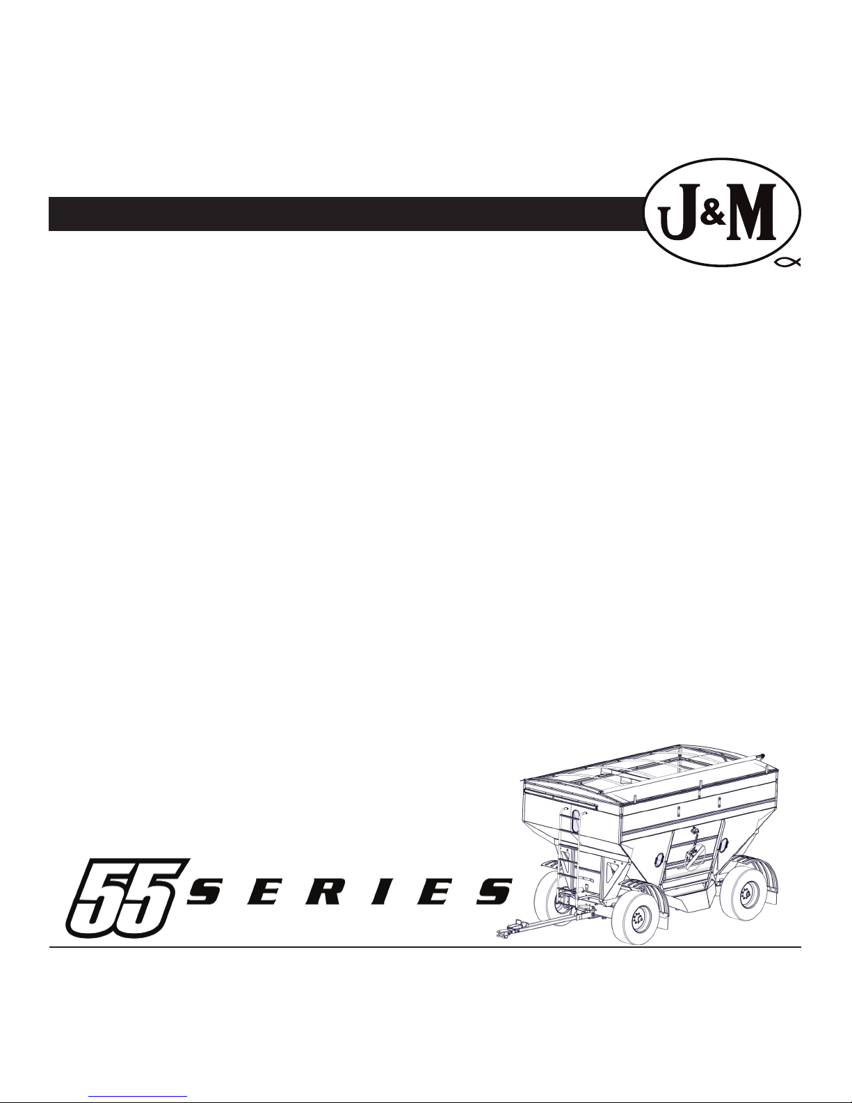
455
555
Gravity Wagon
OPERATORS MANUAL
Rev. 10.23.2018
J. & M. Mfg. Co., Inc.
284 Railroad Street - P.O. Box 547
Fort Recovery, OH 45846
Ph: (419) 375-2376 Fax: (419) 375-2708
www.jm-inc.com
Page 2

Table of Contents
3 .................................................................To the Dealer
4-5 ............................................................... General Information
6 .................................................................Safety Rules
7 .................................................................Specications
8 .................................................................Initial Operation & Maintenance
9 .................................................................Lubrication Service Schedule
10 .............................................................................. Bleeding the Brake Lines / Adjusting the Master Cylinder
11 ................................................................Trail Adjustments
12 ................................................................Running Gear Toe-In
14-15 ............................................................. Safety Signs
16 ................................................................55 Series Tongue Assembly w/ Brakes
17 ................................................................16 Ton Running Gear
18 ................................................................Fender Kit
19 ................................................................Shell Assembly
20 ................................................................Door Wheel Assembly, Inspection Windows
21 ................................................................Door Assembly
22-23 ............................................................. Roll Tarp Assembly
24 ................................................................Light Harness
25 ................................................................13” Brake Assembly
Serial Number Loc ati on
2
Page 3

To The Dealer
Read manual instructions and safety rules. Make sure all items on the Dealer’s Pre-Delivery and Delivery Check Lists are completed
before releasing equipment to the owner.
The dealer must complete the Warranty Registration found on the Dealer Portal website located at dealer.jm-inc.com and return
it to J. & M. Mfg. Co., Inc. at the address indicated on the form. Warranty claims will be denied if the Warranty Registration has not been
submitted.
EXPRESS WARRANTY:
J. & M. Mfg. Co. Inc. warrants against defects in construction or materials for a period of ONE year. We reserve the right to inspect
and decide whether material or construction was faulty or whether abuse or accident voids our guarantee.
Warranty service must be performed by a dealer or service center authorized by J. & M. Mfg. Co., Inc. to sell and/or service the type
of product involved, which will use only new or remanufactured parts or components furnished by J. & M. Mfg. Co., Inc. Warranty
service will be performed without charge to the purchaser for parts or labor based on the Warranty Labor Times schedule. Under no
circumstance will allowable labor times extend beyond the maximum hours indicated in the Warranty Labor Times schedule for each
warranty procedure. The purchaser will be responsible, however, for any service call and/or transportation of the product to and
from the dealer or service center’s place of business, for any premium charged for overtime labor requested by the purchaser, and
for any service and/or maintenance not directly related to any defect covered under the warranty. Costs associated with equipment
rental, product down time, or product disposal are not warrantable and will not be accepted under any circumstance.
Each warranty term begins on the date of product delivery to the purchaser. Under no circumstance will warranty be approved
unless (i) the product warranty registration card has been properly completed and submitted to the equipment manufacturer, and
(ii) a warranty authorization number has been issued by the equipment manufacturer. This Warranty is eective only if the warranty
registration card is returned within 30 days of purchase.
This warranty does not cover a component which fails, malfunctions or is damaged as a result of (i) improper modication or
repair, (ii) accident, abuse or improper use, (iii) improper or insucient maintenance, or (iv) normal wear or tear. This warranty
does not cover products that are previously owned and extends solely to the original purchaser of the product. Should the original
purchaser sell or otherwise transfer this product to a third party, this implied, with respect to tires or other parts or accessories not
manufactured by J. & M. Mfg. Co., Inc. Warranties for these items, if any, are provided separately by their respective manufacturers.
THIS WARRANTY IS EXPRESSLY IN LIEU OF ALL OTHER WARRANTIES OR CONDITIONS, EXPRESS, IMPLIED OR STATUTORY, INCLUDING
ANY IMPLIED WARRANTY OF MERCHANTABILITY OR FITNESS FOR PARTICULAR PURPOSE.
In no event shall J. & M. Mfg. Co., Inc. be liable for special, direct, incidental or consequential damages of any kind. The exclusive
remedy under this Warranty shall be repair or replacement of the defective component at J. & M. Mfg. Co., Inc’s. option. This is the
entire agreement between J. & M. Mfg. Co., Inc. and the Owner about warranty and no J. & M. Mfg. Co., Inc. employee or dealer is
authorized to make any additional warranty on behalf of J. & M. Mfg. Co., Inc.
The manufacturer reserves the right to make product design and material changes at any time without notice. They shall not incur
any obligation or liability to incorporate such changes and improvements in products previously sold to any customer, nor shall
they be obligated or liable for the replacement of previously sold products with products or parts incorporating such changes.
SERVICE:
The equipment you have purchased has been carefully manufactured to provide dependable and satisfactory use. Like all
mechanical products, it will require cleaning and maintenance. Lubricate the unit as specied. Observe all safety information in
this manual and safety signs on the equipment.
For service, your authorized J. & M. dealer has trained mechanics, genuine J. & M. service parts, and the necessary tools and
equipment to handle all your needs.
Use only genuine J. & M. service parts. Substitute parts may void warranty and may not meet standards required for safety and
satisfactory operation. Record the model number and serial number of your equipment in the spaces provided:
Model No: 455-555 Gravity Wagon Serial No: ________________________ Date of Purchase: ___________________
Purchased From: ________________________________________________________________________________
Provide this information to your dealer to obtain correct repair parts.
3
Page 4

General Information
TO THE OWNER:
The purpose of this manual is to assist you in operating and maintaining your gravity wagon in a safe manner. Read it carefully. It
furnishes information and instructions that will help you achieve years of dependable performance and help maintain safe operating
conditions. If this machine is used by an employee or is loaned or rented, make certain that the operator(s), prior to operating:
1. Is instructed in safe and proper use.
2. Reviews and understands the manual(s) pertaining to this machine.
Throughout this manual, the term IMPORTANT is used to indicate that failure to observe can cause damage to equipment. The terms
CAUTION, WARNING and DANGER are used in conjunction with the Safety-Alert Symbol, (a triangle with an exclamation mark), to
indicate the degree of hazard for items of personal safety. When you see this symbol, carefully read the message that follows and be
alert to the possibility of personal injury or death.
This Safety-Alert symbol indicates a hazard and means
ATTENTION! BECOME ALERT! YOUR SAFETY IS INVOLVED!
DANGER
WARNING
CAUTION
IMPORTANT
NOTE
Indicates an imminently hazardous situation that, if not avoided, will result in death or serious injury.
Indicates a potentially hazardous situation that, if not avoided, could result in death or serious injury,
and includes hazards that are exposed when guards are removed.
Indicates a potentially hazardous situation that, if not avoided, may result in minor or moderate injury.
Indicates that failure to observe can cause damage to equipment.
Indicates helpful information.
4
Page 5
General Information
BOLT TORQUE CHART
Always tighten hardware to these values unless a dierent torque or tightening procedure is listed for specic application.
Fasteners must always be replaced with the same grade as specied in the manual parts list.
Always use the proper tool for tightening hardware: SAE for SAE hardware and Metric for Metric hardware.
Make sure fastener threads are clean and you start thread engagement properly.
All torque values are given to specications used on hardware dened by SAE J1701 & J1701M (JUL 96)
A
Diameter
(Inches)
1/4
5/16
3/8
7/16
1/2
9/16
5/8
3/4
7/8
1
Diameter
&
(Millimeters)
Thread Pitch
6 x 1.0
8 x 1.25
10 x 1.5
12.1.75
14 x 2.0
16 x 2.0
18 x 2.5
20 x 2.5
22 x 2.5
24 x 3.0
30 x 3.0
SAE SERIES
TORQUE
A
CHART
Wrench
Size
7/16”
1/2”
9/16”
5/8”
3/4”
13/16”
15/16”
1-1/8”
1-5/16”
1-1/2”
METRIC SERIES
TORQUE
A
CHART
Wrench
Size
10 mm
13 mm
16 mm
18 mm
21 mm
24 mm
27 mm
30 mm
34 mm
36 mm
46 mm
109
169
234
330
451
571
1175
SAE Bolt Head
Identication
SAE Grade 2
(No Dashes)
SAE Grade 5
3 Radial Dashes
SAE Grade 8
6 Radial Dashes
MARKING ON HEAD
SAE 2
LBS.-FT.
6
12
23
36
55
78
110
192
306
467
8
17
31
48
75
106
149
261
416
634
8.8
Metric
Grade 8.8
COARSE THREAD FINE THREAD
8
20
39
68
125
172
244
332
421
867
6
15
29
50
80
11
27
54
94
151
234
323
457
623
790
1626
1199
LBS.-FT.
Metric Bolt Head
Identication
8
20
40
70
111
173
239
337
460
583
SAE 5 SAE 8
N-m N-m
10
19
35
55
85
121
170
297
474
722
13
26
47
75
115
164
230
403
642
979
10.9
Metric
Grade 10.9
MARKING ON THREADMARKING ON THREAD
11
29
57
103
163
250
363
507
684
861
1740
21
41
75
118
181
263
367
495
623
1258
8
6
16
30
55
87
133
194
270
365
459
928
Metric 10.9Metric 8.8Metric 8.8 Metric 10.9
LBS.-FT.N-m
120
171
240
420
669
1020
14
27
49
78
22
42
76
120
184
268
374
505
635
1283
18
37
67
106
163
232
325
569
907
1383
Diameter
&
(Millimeters)
Thread Pitch
8
6 x 1.0
8 x 1.0
10 x 1.25
12.1.25
14 x 1.5
16 x 1.5
18 x 1.5
20 x 1.5
22 x 1.5
24 x 2.0
30 x 2.0
Standard 5/8” wheel bolts should be tightened to torque 350 Ft.-Lbs. During initial operation of the gravity wagon and then checked
for proper torque after every 10 hours of use. Failure to do so may damage wheel nut seats. Once seats are damaged, it will become
impossible to keep nuts tight. The correct tire pressure for the 165-225 x135 tire is 85 PSI.
TIGHTENING WHEEL NUTS & TIRE PRESSURE
5
Page 6

Safety Rules
ATTENTION! BECOME ALERT! YOUR SAFETY IS INVOLVED!
• Safety is a primary concern in the design and manufacture of our products. Unfortunately, our eorts to provide safe equipment
can be erased by an operator’s single careless act. In addition, hazard control and accident prevention are dependent upon the
awareness, concern, judgment, and proper training of personnel involved in the operation, transport, maintenance and storage
of equipment.
• Make certain that the operator(s), prior to operating is instructed in safe and proper use and reviews and understands the manual(s)
pertaining to this machine.
• Read this manual before you operate this machine. If you do not understand any part of this manual, or need more information,
contact the manufacturer or your authorized dealer.
SAFETY RULES
1. Understand that your safety and the safety of other persons
are measured by how you service, and operate this machine. Know
the positions and functions of all controls before you try to operate
them. Make sure to check all controls in a safe area before starting
your work.
2. The safety information given in this manual does not replace safety
codes, federal, state or local laws. Make certain your machine has the
proper equipment as designated by local laws and regulations.
3. A frequent cause of personal injury or death is from persons falling
o equipment and being run over. Do not permit persons to ride on
this machine.
4. Travel speeds should be such that complete control and machine
stability is maintained at all times. Where possible, avoid operating
near ditches, embankments and holes. Reduce speed when turning,
crossing slopes and rough, slick or muddy surfaces.
5. Collision of high speed road trac and slow moving machines can
cause personal injury or death. On roads, use asher lights according
to local laws. Keep slow-moving-vehicle emblem visible. Pull over to let
faster trac pass.
6. Make sure that the implement is fastened securely to the tractor
/truck by using the proper hitch pin, clip and safety chains.
9. IMPORTANT: Use caution when transporting. Be alert of the
transport unit’s overall width when approaching obstacles, such as
post signs and poles, along the road. Check the transport width of
the unit to ensure clearance before entering bridges.
10. Do not allow anyone to stand between tongue or hitch and
towing vehicle when backing up.
11. Choose the most level route possible when transporting across
elds.
12. Never adjust, service, clean, or lubricate gravity box until all
power is shut o.
13. Keep all safety shields in place. Keep hands, feet, hair, and clothing
away from the moving parts while the unit is in operation.
14. The service ladder is for service work only. If you must climb into
the grain tank, be certain that all power is shut o and then use
extreme caution when climbing into the grain tank. Never allow
anyone in, near or on the gravity box during transporting or unloading grain. Moving grain is dangerous and can cause entrapment,
resulting in severe injury or death by suocation.
15. Make sure that everyone is clear of equipment before applying
power or moving the machine.
7. Before unhooking the implement from the towing unit, be sure
to properly block the wheels to prevent the implement from moving.
8. Never overload the wagon. Overloading the wagon is dangerous
and can cause extensive damage. Never add more sideboards to the
gravity box than what is recomended, as the box is not designed to
carry the additional weight. Do NOT exceed speeds in excess of 20 MPH.
Rim, hubs and bearings are designed for heavy loads at slow speeds.
Also be sure slow moving vehicle emblem is attached to the rear of the
wagon.
14. COMPLY WITH ALL SAFETY WARNINGS AND CAUTIONS IN
THIS MANUAL AND IN THE COMBINE OPERATORS MANUAL
WARNING: BE SURE ALL LIGHTS ARE WORKING PROPERLY
BEFORE HIGHWAY TRAVEL.
6
Page 7
Specications
Wagon Specications
Capacity - Box*
Door Width
Chute Height
Hopper Construction
Understructure
Taillights
Front Ladder
Center Dump Deector
Capacity - Running Gear
Spindles
Wheels
455/555
450/560
60”
Adjustable 14” to 19”
12 GA & 9 GA Steel
3” x 6” Runners
Standard
Standard
Optional
16 Ton HD
3” Diameter
22.5 x 13.5 -8 Bolt
455
A
16’
B
7’-2”
C
9’-5”
D
7’-4”
E
11’
F
9’
G
23’-8”
H
1’-3”
555
16’
8’
10’
7’-4”
11’
9’
23’-8”
1’-3”
655
17’-7”
7’-11”
10’-5”
7’-8”
11’-5”
9’-6”
25’-4”
1’-5”
755
17’-7”
8’-7”
11’-2”
7’-8”
11’-5”
9’-6”
25’-4”
1’-5”
655/755
660/760
60”
Adjustable 14” to 19”
12 GA & 9 GA Steel
3” x 6” Runners
Standard
Standard
Optional
24 Ton HD
3-3/8” Diameter
22.5 x 13.5 -8 Bolt
Tires
Hydraulic Brakes
Weight (complete unit)
* Bushel capacity measured with #2 corn at 15% moisture (56 lbs. test weight)
15 -22.5 or 16.5 -22.5
Optional 2-Whl Drum
5,796 lbs./6,030 lbs.
15 -22.5 or 16.5 -22.5
Optional 4-Whl Drum
6,800 lbs./7,050 lbs.
Model USA-15 Specications
Diameter
Length
Flighting
Hopper
Auger Tube
Winch
Auger Pivot
Sump Design Hopper
Unloading Height
Height of Auger in Saddle
Maximum Swing Left and Right
Maximum Unloading Distance Out
Discharge Rate (corn/soybeans)*
Discharge Rate (fertilizer)*
* Your rate may dier due to the quality of the material, the auger unloading height angle, and variable tractor hydraulic output. NOTE: Always
operate the auger system with a tractor hydraulic requirement of 9 gpm (minimum) to 15 gpm (maximum) (2,250 psi)
6 inch
15’-0”
Steel or Poly-Cup Plastic
Adjustable to t almost any box
14 GA seamless steel tube
Standard
Patented Uni-Swivel Design
Yes
11’-0” (maximum); 7’-0” (minimum)
10’-0” (on 385 box to steel spout)
43’-0” (with 3-Stage Telescoping Spout)
19’-0” (with 3-Stage Telescoping Spout)
15 bushels per minute
1,000 lbs. per minute
GUARANTEE
J. & M. MANUFAC TURING CO. guarant ees against a ny faulty con structi on or
materia ls for a period o f ONE year. We reser ve the right to ins pect and
decide whether material or construction was faulty or whether abuse or
accident voids our guarantee.
Specications are subject to change without notice or obligation.
® Regist ered Trademar k of J.& M. Mfg., Co. Inc .
7
Page 8
Initial Operation / Maintenance
WARNING BE CERTAIN THAT ALL POWER IS SHUT OFF BEFORE SERVICING THE GRAVITY BOX.
Before the gravity box is put into service:
Has the track assembly (opens door) been lubricated for less wear on the sprocket and track and for easier door operation.
Has the SMV (Slow Moving Vehicle) Emblem been positioned with a point of the triangle upward and as near to the rear and
centered or as near to the left of center of the unit as practicable? Is it located two to ten feet above the ground measured
from the lower edge of the emblem?
Has the gravity box been properly attached to the running gear? If no rocking bolster is used, bolt all four corners (use 1/2”
bolts provided) of the gravity box runners to the running gear. (If the box is used in rough terrain, bolt a minimum of two
corners and chain (or cable) the remaining corners to allow more box exibility.
Have all braces, bolts, nuts, lug bolts, and lug nuts been checked to ensure that they are properly fastened?
NOTE: The proper torque for the wheel lug nuts is 350 ft lbs.
Have the safety instructions been read and clearly understood by the operator(s) of this machine.
Do the lights work properly? Are all reective decals clean and visible? Are they positioned correctly?
Are the tires properly inated? The following is to be used as a general guide for tire ination for cyclic use. Figures can vary
depending on specic brand of tire used. It is important that tires are inspected before and after the unit is loaded. The
tire should stand up with no side wall buckling or distress as the tire rolls. Do Not Exceed The Tire Pressure Indicated
Below:
Tire Size psi
BRAKING SYSTEM REQUIREMENTS
WARNING Tow Loads Safely
Stopping distance increases with speed and weight of towed loads, and on slopes. Towed loads with or without brakes that
are too heavy for the tractor or are too fast can cause loss of control. Consider the total weight of the equipment and its load.
For towed equipment WITHOUT brakes, the following is recommended:
Do NOT tow equipment that does not have brakes at speeds over 32 km/h (20 mph); or that, when fully loaded, has a mass
(weight) over 1.5t (3300 lb) and more than 1.5 times the mass (weight) of the towing unit.
For towed equipment WITH brakes, the following is recommended:
Do NOT tow equipment that has brakes at speeds over 40 km/h (25 mph); or that, when fully loaded, has a mass (weight) more
that 4.5 times the mass (weight) of the towing unit.
Ensure the load does not exceed the recommended weight ratio. Use additional caution when towing loads under adverse
conditions, when turning and on inclines.
WARNING
Before lling the gravity box, make certain that no one is inside the grain tank. Never allow children or anyone in, near, or on
the gravity box during transport or during loading or unloading of grain. Be aware that moving grain is dangerous and can
cause entrapment, resulting in severe injury or death by suocation.
After hauling corrosive materials such as fertilizers, be sure to wash out the grain tank to prevent premature rusting. Bare
spots on metal should be primer coated before applying the outer surface paint.
385/65R22.5 70
425/65R22.5 85
Check the box periodically for cracks in welds and for other structural damage. Have cracked welds fixed immediately.
Failure to do so could result in extensive damage and greatly reduce the life of the gravity box.
8
Page 9

Lubrication Service Schedule
IMPORTANT: Your Gravity Wagon has grease ttings at all critical points. These should be serviced before the
Gravity Wagon is put into operation each season.
IMPORTANT: Your Gravity Wagon is equipped Oil Bath Hubs that should be ushed once a year. Follow the steps below:
HOW TO FLUSH THE OLD OIL OUT OF THE OIL BATH HUBS
Before you begin check the hub for leaks and wear. Replace components as necessary.
1.) Roll the hub until the ll plug is on top.
2.) Drain the hub by removing the cap.
3.) Use light weight motor oil to ush out remaining oil. (After draining the old oil)
*There is no need to tilt the hub, the oil will ow through the bearing easily.
4.) Replace cap. Torque cap to 30-40 ft. lbs.
5.) Replace oil with 80-90WT Sta-Lube from NAPA. (This oil has a rust inhibitor additive)
HOW TO ADD OIL TO OIL BATH HUBS
IMPORTANT: Use Napa STA-Lube - GL5 80/90 WT with Rust Inhibitors FL2472 for the Oil Bath Hubs.
1.) Remove breather plug. (3/4” Wrench)
2.) Use an oiler hand pump to add 80-90WT Sta-Lube oil from NAPA.
It takes 8 ounces to ll hubs to the recommended level.
3.) Replace breather plug. First hand tighten, then use 3/4” wrench to make a 1/4” of a turn.
Routine Maintenance
WARNING BE CERTAIN ALL POWER IS SHUT OFF WHEN SERVICING THE GRAVITY WAGON.
• Check the gravity wagon periodically for cracks in welds and for other structural damage. Have cracked welds xed immediately.
Failure to do so could result in extensive damage to the gravity wagon and greatly reduce the life of the unit.
• Check all hydraulic hoses for wear and replace as necessary. (If equipped)
• Make sure all tires are properly inated. See INITIAL OPERATION AND MAINTENANCE in the Owner’s Manual for recommended
instructions for tire pressure. It is important that tires are inspected before and after unit loaded.
• Follow the lubrication service schedual above to ensure proper lubrication.
• Check that the lug nuts are properly torqued to 350 ft lbs.
Your local, authorized dealer can supply genuine replacement parts. Substitute parts may not meet original equipment specications and may be dangerous.
When performing maintenance work, wear sturdy, rough-soled work shoes and protective equipment for eyes, hair, hands, hearing
and head. Follow Operator’s Manual instructions to ensure safe and proper maintenance and repair.
BE CERTAIN THAT ALL POWER IS SHUT OFF TO THE GRAIN CART BEFORE PERFORMING ANY MAINTENANCE OR REPAIR WORK.
Storage Preparation
IMPORTANT: When the gravity wagon is not going to be used for a period of time, store the unit in a dry, protected place. Leaving
your gravity wagon outside, open to the weather will shorten it’s life.
Follow the procedure below when your gravity wagon is placed in storage for periods up to six months.
1. Wash or clean and completely lubricate the grain cart. See the lubrication service section in this manual.
2. Remove all grain from inside the grain tank.
3. Touch up areas where paint may have worn away. Use a good quality primer paint, especially before re-applying graphite paint
to the interior slopes of the grain tank.
4. Clean the tires before storage. Inate the tires at regular intervals.
9
Page 10

Bleeding The Brake Lines
METHOD ONE (requires two people)
Close all bleed screws.
Start with the wheel furthest from the master cylinder. Slip a transparent bleed hose on the bleeder stem and place the other end
of the hose in a clean container which is partially lled with uid at all times.
The rst person depresses the brake plunger SLOWLY (take 3-5 seconds). THEN the second person opens the bleed screw. He then
closes the bleed screw BEFORE the rst person SLOWLY releases the plunger (3-5 seconds). Continue until there is no evidence of
air in the bleed hose. Continue with remaining wheels working from the longest to the shortest distance from the master cylinder.
Top o master cylinder as needed to prevent reintroducing air into the lines.
IMPORTANT:
1) Depress plunger slowly
2) Open bleed screw
3) Close bleed screw
4) Release plunger slowly
METHOD TWO (one person)
Attach bleed hose to rear wheel as in method one. Open bleed screw. SLOWLY depress plunger (3-5 seconds). Repeat until line is
air free. Close bleed screw. Top o master cylinder as needed to prevent reintroducing air into the lines.
Repeat with remaining wheels.
DANGER: Contamination with dirt, water, petroleum products or other materials may result in
brake failure or costly repairs.
Adjusting the Brake Master Cylinder
1) Remove the shield. Use a 9/16” wrench to remove the (2) 3/8” x 1” serrated hex head bolts from shield.
2) Loosen the 1/2” nut on the plunger pin. Use a 3/4” wrench.
3) Rotate the plunger rod to adjust.
- For more aggressive braking action turn the plunger rod counterclockwise. (This will lengthen the assembly)
- For less aggressive braking action turn the plunger rod clockwise. (This will shorten the assembly)
DANGER: Do not adjust all the “Play” out of the plunger system. This will cause the brakes to be activated at
all times and over heat the drums causing failure.
NOTE: This braking system is to assist the pull vehicle in the braking mode, not to take the place of it.
The braking plunger system should have approximately a 1/4” of “play” when adjusted for level road travel.
4) Tighten the 1/2” hex nut to keep plunger rod in place.
5) Put the shield back on and tighten both 3/8” x 1” SF hex bolts.
10
Page 11

Gravity Wagon Trail Adjustment
• Keep tongue bolt tightened. The tongue bolt should be as tight as possible without over restricting the vertical
motion of the hitch.
• An extra washer (shown below) can be added if the nut is tightened so far that it runs out of threads before the
tongue bolt is as tight as possible.
Hitch
Tong ue Ea r
• Tires should be inated to the manufactures specications.
• For running gears equipped with used tires, If either of the front tires look to be excessively worn or unevenly
worn they should be rotated with a less worn rear tire, if possible.
• The front tires should be towed in 3/16” on front overall, from rim to rim. 1/8” Min to 1/4” Max.
• Make sure the inner tongue bolt (shown below) is tightened enough to mitigate slop but still allow the inner
tongue to slide in and out of the outer tongue. It is acceptable to see the outer tongue squeezed inward by the
inner tongue bolt for a slop free t.
Outer Tongue
Inner Tongue Bolt
11
Page 12

Adjusting Running Gear Toe-In
• Locate the tongue in the straight and horizontal position. Check this by measuring both “L1” locations. Once both
locations are the same length, move onto the next step.
• Measure both “L2” locations. Adjust both tie-rods to assure both measurments are equal, if necessary.
• Finish with taking measurments for “L3” and “L4.” L3 should be set 3/16” smaller than L4 by adjusting the tie-rods in
equal amounts.
• Measure both “L2” locations again. If both measurement are the same you are nished. If measurments are not the
same, repeat the entire process.
L1
L1
L2
L3
Tie-Rods
L4
L2
12
Page 13

13
Page 14

SpecicationsSafety Signs
ATTENTION! BECOME ALERT! YOUR SAFETY IS INVOLVED!
Replace Immediately If Damaged or Missing
IMPORTANT: Install new safety signs if the old signs are destroyed, lost, painted over or cannot be read.
When parts are replaced that have safety signs, make sure you install a new sign with each new part. New
signs are available from the manufacturer or your authorized dealer.
3
1
2
13
14
4
5
6
7
8
10
11
12
9
1 J&M Oval Small JM0015150
1 J&M Oval Large JM0015151
2 www.jm-inc.com JM0019239
3 Danger - Flowing Grain Traps JM0019223
4 Check All Wheel Nuts JM0018043
5 Check Tire Ination JM0018041
6 For Farm Use Only JM0018038
7 Caution - Check Fluid Level JM0019229
8 Warning - Keep Lug Nuts JM0024420
9 Door Light JM0036562
10 Yellow Reective JM0009946
11 Red Reective JM0009945
12 Orange Reective JM0009944
13 Caution - Fasten Box Securely JM0019228
14 Keep Lug Nuts and Lug Bolts JM0019220
15 455 Passenger Side Decal JM0036547
16 455 Drivers Side Decal JM0036546
17 455 Decal Kit (Items 1-16) JM0036566
18 555 Passenger Side Decal JM0036543
19 555 Drivers Side Decal JM0036545
20 555 Decal Kit (Items 1-14,18,19) JM0036567
14
Page 15

SpecicationsSafety Signs
550+ Bushel Capacity
CAUTION
FASTEN BOX SECURELY TO WAGON GEAR.
KEEP AWAY FROM MOVING PARTS.
DO NOT CLIMB INTO GRAVITY TANK.
BEFORE HIGHWAY TRAVEL, SECURE A
SLOW-MOVING VEHICLE EMBLEM TO THE
REAR OF THE BOX IN ACCORDANCE WITH
STATE AND LOCAL LAWS.
MAKE SURE ALL FLASHER AND TURN
INDICATOR/BRAKE LIGHTS ARE WORKING
PROPERLY BEFORE INCIDENTAL HIGHWAY
TRAVEL.
550+ Bushel Capacity
550+ Bushel Capacity
CAUTION
FASTEN BOX SECURELY TO WAGON GEAR.
KEEP AWAY FROM MOVING PARTS.
DO NOT CLIMB INTO GRAVITY TANK.
BEFORE HIGHWAY TRAVEL, SECURE A
SLOW-MOVING VEHICLE EMBLEM TO THE
REAR OF THE BOX IN ACCORDANCE WITH
STATE AND LOCAL LAWS.
MAKE SURE ALL FLASHER AND TURN
INDICATOR/BRAKE LIGHTS ARE WORKING
PROPERLY BEFORE INCIDENTAL HIGHWAY
TRAVEL.
550+ Bushel Capacity
15
Page 16

55 Series Tongue Assembly w/ Brakes
# Description Part. No.
1 3/8”-16 x 1” Gr5 Z SF Hex Bolt (381-FB) JM0002092
2 Shield for Master Cylinder (SMC-1) JM0019273
3 5/16”-18 x 3” Gr5 Z Hex Bolt JM0019359
4 Rubber Boot for Master Cylinder (RB-1415) JM0019358
5 455/555 Plunger Pole 47-1/4” Long JM0035046
6 1-1/4” Tongue Bolt 16 Ton (TB-1315) JM0019324
7 1/2”-13 Gr5 Z SF Hex Nut (12-N) JM0002153
8 1/4”-20 x 1/2” Gr5 Z Hex Bolt (1412-HB) JM0001481
9 1/4” USS Flat Washer (14-W) JM0003090
10 Mounting Bracket for Master Cylinder(2 pcs.)(MBMC-DR2) JM0019340
11 1/2”-13 Gr5 Z J-Bolt JM0002168
12 1/4”-20 Gr5 Z Centerlock Hex Nut (14HN) JM0001505
13 1-1/4” USS Flat Washer JM0010112
14 1-1/4”-7 Gr5 Z Centerlock Hex Nut JM0002150
15 1-1/4” King Pin 16 Ton (KP-1215) JM0019332
16 Hitch Weldment (HW-16) JM0015746
17 3/4” ID x 7/8” OD x 5/8” LG Bronze Bushing (BB-34) JM0009455
18 Tongue Spring 3/8” x 1-3/4” x 12-1/2” (TS-615H) JM0014200
19 1/4”-20 x 3/4” Gr5 Z Hex Bolt (1434-HHMB) JM0001507
20 5/16”-18 Gr5 Z Star Washer Hex Nut JM0019361
# Description Part. No.
21 .015 Orice Restrictor JM0027857
22 Master Cylinder with Spring Bracket (MCA-DR1) JM0019356
23 Master Cylinder Cap (RCMC-1324) JM0019357
24 Master Cylinder Push Pin (PRE-1) JM0019341
25 1/2”-13 Gr5 Z Hex Nut JM0002124
26 Seal Kit for Master Cylinder (Not Shown)(SKMC-1324) JM0036060
27 Tongue Latch (TL-1324) JM0019289
28 1”-8 Gr5 Z Centerlock Hex Nut (1G5LN) JM0002149
29 Compression Spring (CM1516112) JM0019293
30 Small Spring in Latch (DS-250) JM0001688
31 1”-8 x 7” Gr5 Z Hex Bolt JM0016689
32 1”-8 x 9” Gr8 Z Hex Bolt (19G8B) JM0001708
33 Brake Limiter (BL-58) JM0019306
34 7/8”-9 x 6” Gr8 Z Hex Bolt JM0032815
35 1”-8 x 7-1/2” Gr8 YZ Hex Bolt JM0017944
36 7/8”-9 Gr5 Z Centerlock Hex Nut JM0002148
37 Rubber Bar for Inner Tongue (3-15/16” x 3-1/8” x 1-1/4”) JM0032331
38 55 Series, Clevis Hitch JM0032324
39 55 Series, Inner Tongue (Less Hitch) JM0033959
40 55 Series, Hitch Weldment Only JM0035373
41 Complete 55 Series Tongue Assembly (No Brakes) JM0036217
16
Page 17

16 Ton Running Gear (JM0032018)
IMPORTANT: Use Napa STA-Lube - GL5 80/90 WT with Rust Inhibitors
FL2472 for the Oil Bath Hubs.
Coupling Pole
Tie-Rod Assembly (Item 42)
# Description Part. No
24 85-8 Oil Bath Seal - 15 (16) Ton JM0035245
25 Bearing, Large (Inner) 15 Ton (387-AS) JM0018101
26 Cup, Large (Inner) 15 Ton (382A) JM0018100
27 Wheel Stud (Lug) - 15 Ton (WB-15) JM0019235
28 5/8”-18 Flange Lugnut (WN-15F) JM0019246
29 G85-8 Oil Bath Outer Bearing Cup (16T) JM0035896
30 G85-8 Oil Bath Small Outer Bearing (16T) JM0035898
# Description Part. No
1 55 Series, 16 Ton, Front Right A-Frame Arm JM0035905
2 Hitch Weldment 16 Ton JM0015746
3 3/4” Bronze Bushing (BB-34) JM0009455
4 1-1/4”-7 Gr5 Z Centerlock Hex Nut JM0002150
5 1-1/4” USS Flat Washer JM0010112
6 1/8” Grease Zerk (1610BL) JM0009756
7 King Pin Vertical Hitch Bolt (1-1/4” x 9 1/2”) JM0019332
8 Spindle Bolt (1-3/4” x 13 1/2”) (SPB-134) JM0019321
9 1-3/4” ID Bronze Bushing (2” OD x 1” Length) JM0002244
10 55 Series, 16 Ton, Front Left A-Frame Arm JM0035903
11 G85-8 Oil Bath Hub, w/Studs, Nuts & Races (16T ) JM0035900
12 1-3/4” USS Flat Washer JM0029723
13 1-3/4”-5 Gr5 Hex Nut (HN-134) JM0019334
14 55 Series, 16 Ton, Front A-Frame Weldment JM0031038
15 1”-8 x 6-1/2” Gr5 Z Hex Bolt JM0014192
16 4-1/2” Collar to Coupling Pole (CL-412) JM0015724
17 1”-8 Gr5 Z Centerlock Hex Nut (1G5LN) JM0002149
18 1” ID x 3/16” GW x 1-3/8” GD Grommet JM0016784
19 Rubber Damper (1/2”-13 x 1-1/4” Stud) JM0031630
20 1/2”-20 Gr5 Z Centerlock Hex Nut JM0009858
21 1” ID x 1/4” GW x 1-3/8” GD - PN 3119 Grommet JM0031895
22 55 Series. 16 Ton, Rear A-Frame Weldment JM0031035
23 G85-8 Oil Bath Brake Hub, w/Studs, Nuts & Races JM0035879
31 1-1/4” Z Flat Washer (2-1/2” OD) JM0020322
32 1-1/4”-12 Gr5 Z Slotted Spindle Nut (912969) JM0010113
33 3/16” x 1-1/2” Cotter Pin JM0015883
34 Oil Bath Dust Cap for Threaded G848OB Hub (16T) JM0025747
35 3/4” x 2-1/4” Step Bolt and Nut for Tie Rod End (SB-34) JM0003181
36 3/4” Nut for Step Bolt JM0003184
37 Tie Rod End, Left Hand Thread (clevis type) 12-15 Ton (TRE-1L) JM0019189
38 1”-14 (ne thread) Hex Nut, L/H, for Tie Rod, 12-15 Ton (HN-1L) JM0014281
39 Tie Rod (1” x 19”) 12-15 Ton (TR-20) JM0019190
40 1”-14 (ne thread) Hex Nut, R/H, for Tie Rod, 12-15 Ton (HN-1R) JM0014282
41 Tie Rod End, Right Hand Thread (clevis type) 12-15 Ton (TRE-1R) JM0001822
42 Tie-Rod Complete (1” x 19”) (Minus items 35 & 36) JM0036226
43 Coupling Pole 55 Series (4” O.D. x 138” L Pipe) JM0031296
44 Left A-Frame Weldment & Spindle Complete JM0036244
45 Right A-Frame Weldment & Spindle Complete JM0036245
46 7/8 - 9 X 8 Gr8 Z Hex Bolt JM0019392
47 7/8 USS Flat Washer JM0014395
48 1/2"-13 Gr5 Z Centerlock Hex Nut JM0001511
49 1/2 USS Flat Washer JM0003082
50 16 Ton Back Rocking Bolster JM0031045
51 16 Ton Back Rocking Bolster Spacer JM0032207
52 1/2 - 13 x 6-1/2” Gr5 Z Hex Bolt JM0016680
7/8 - 9 Gr5 Z Centerlock Hex Nut JM0002148
53
17
Page 18

Fender Kit
# Description Part. No
1 3/8”-16 x 1-3/4” Gr5 Z SF Hex Bolt JM0002097
2 3/8” USS Flat Washer JM0003061
3 3/8”-16 Gr5 Z Centerlock Hex Nut JM0001512
4 Gravity Box Mud Flap JM0033494
5 Front Lower Left Fender Bracket (455, 555) JM0033398
6 Square U-bolt 6” x 4-5/8” x 3/8”-16 JM0033399
7 3/8”-16 Gr5 Z SF Hex Nut JM0002152
8 55 Series, Fender JM0033393
9 3/8”-16 x 1” Gr5 Z SF Hex Bolt JM0002092
10 Front Upper Left Fender Bracket (55 Series) JM0033395
11 Front Upper Right Fender Bracket (55 Series) JM0033435
12 Front Lower Right Fender Bracket (455, 555) JM0033437
13 Rear Lower Left Fender Bracket (455, 555) JM0033426
14 Rear Lower Right Fender Bracket (455, 555) JM0033428
15 7/16” ID x 2-1/2” USS Flat Washer JM0018982
# Description Part. No
1 Wheel 22.5 x 13.5-8 Bolt JM0019398
2 165-225x135 Used Tire JM0019399
3 Wheel & Tire 425/16.5 x 22.5 JM0036257
18
Page 19

Shell Assembly
555 Divider Option Only
# Description Part. No
1 3/8”-16 x 1” Gr5 Z SF Hex Bolt (381-FB) JM0002092
2 555 Sideboard Corner (10-1/4”) JM0033237
3 3/8”-16 Gr5 Z SF Hex Nut (38-FN) JM0002152
4 555 Left or Right Sideboard JM0033198
5 555 Endboard JM0033212
6 455/555 Cross Centerbrace JM0033193
7 Flat Washer (7/16” ID, 2 1/2” OD, 1/8” Thick Zinc)(12-W-212) JM0018982
8 Divider End Tab (555) JM0035861
9 Divider Sideboard (555) JM0035857
10 1/4” USS Flatwasher JM0003090
11 1/4”-20 x 3/4” Gr5 Z Hex Bolt JM0001507
12 1/4”-20 x 1” Gr5 Z Hex Bolt (141G5B) JM0002095
13 Wire-Harness Storage Bracket (WHB-1) JM0001438
14 1/4”-20 Gr5 Z SF Hex Nut JM0001630
15 55 Series Ladder Brace JM0034491
16 1/4”-20 Gr5 Z Centerlock Hex Nut JM0001505
17 Manual Canister (OMST-1) JM0010115
18 Ladder Weldment (455, 555) JM0033719
19
Page 20

Door Wheel Assembly
Gear Reduction
Wheel Assembly
# Description Part. No
1 Rear Mounting Plate (RMP-1) JM0028412
2 3/8”-16 x 1” Gr5 Z Serrated Flange Hex Bolt JM0002092
3 3/4” ID Bronze Bushing (BB-34) JM0009455
4 1/4”-20 Gr5 Z Centerlock Hex Nut (14HN) JM0001505
5 3/4” Z Flat Washer (2” OD) (34FW) JM0010006
6 1/4”-20 x 1” Gr5 Z Hex Bolt (141G5B) JM0002095
7 Door Locking Rod (DLR-1) JM0019097
8 Rubber End Cap (REC-1) JM0016842
9 3/8”-16 x 1-3/4” Gr5 Z Hex Bolt JM0002097
10 Gear 15 Tooth 3/4 Bore w/ Shaft Weldment (15TSS) JM0028411
11 38 Tooth Sprocket w/ Shaft (Gear Reduction Rack) JM0028410
12 3/8”-16 Gr5 Z Centerlock Hex Nut (38G5LN) JM0001512
13 3/8”-16 Gr5 Z Serrated Flange Nut (38-FN) JM0002152
14 Front Cover Plate (FCP-1) JM0028409
15 55 Series 24" Door Rack Wheel JM0035347
15 16-3/4” Door Rack Wheel (Divider Assembly Only) JM0028404
16 Track and Chain Assembly (TCA-28) JM0028403
17 Gear Reduction Wheel Assembly (Minus Track & Chain) JM0033488
Inspection Window
Kit
Inspection Windows
# Description Part. No.
1 3/8”-16 Gr5 Z Centerlock Hex Nut (161900) JM0001512
2 Inside Window Brace (WB-4) JM0000253
3 Outside Window Brace (WB-4B) JM0000256
4 3/8-16 x 3/4” Gr5 Z Hex Bolt (161000) JM0001663
5 Oval Window Grommet (62095-7) JM0000254
6 Oval Window (IW-71212) JM0000255
7 Inspection Window Kit (IWK-1) JM0025752
8 XL Oval Window JM0033504
9 XL Oval Window Grommet JM0033502
20
Page 21

Door Assembly
Option
Divider OptionNon-Divider
# Description Part. No
1 Field Light (LED) (FLDLT-1) JM0037154
2 3/8”-16 Gr5 Z SF Hex Nut (38-FN) JM0002152
3 3/8”-16 x 1” Gr5 Z SF Hex Bolt (381-FB) JM0002092
4 3/16” 55 Series Chain With S-Hook JM0019107
5 1” Wide Poly Tape (attached to door) JM0035980
6 1/2” Z Washer (2 1/4” OD) (12214W) JM0019081
7 1/4” Diameter Snap Ring Lynch Pin (CTE-LP) JM0001870
8 Adjustable Chute Bracket for 60" Door (55 Series) JM0035050
9 Dump Chute Weldment - 60” Door (55 Series) JM0031201
10 55 Series Non Metering Door Weldment JM0032062
11 55 Series Divider Door Weldment JM0036037
12 55 Series Center Dump Chute JM0031209
13 3/8"-16 Gr5 Z Hex Nut JM0001707
14 3/8"-16 x 1-1/2" Gr5 Z Hex Bolt JM0001659
21
Page 22

Roll Tarp
# Description Part. No.
1 455/555 Front Face Plate JM0033224
2 Tarp Nylon Riser (TNR1) JM0000196
3 455/555 Endcap Front (Top) JM0033227
4 1/4”-20 x 1/2” Gr5 Z Hex Bolt (1412-HB) JM0001481
5 1/4”-20 Gr5 Z Serrated Flange Hex Nut JM0001630
6 1/4”-20 x 5/8” Gr5 Z Hex Bolt (1458-HB) JM0001479
7 455/555 Endcap Rear (Top) JM0033233
8 3/8”-16 Gr5 Z J-Bolt (384JB) JM0001519
9 3/8”-16 Gr5 Z Centerlock Hex Nut (38LN) JM0001512
10 455/555 Rear Faceplate JM0033231
11 1/4” ID, 3/4” OD Z Flat Washer (14-W) JM0003090
12 Tarp Stando JM0001889
13 1/4” x 1-1/2” Self Tapping Screw (38STS) JM0001571
14 Box Tarp Prop (EPB-1) JM0000917
15 3/8”-16 Gr5 Z Serrated Flange Nut (38-FN) JM0002152
16 3/8”-16 x 1” Gr5 Z Serrated Flange Hex Bolt (381-FB) JM0002092
17 3/8”-16 x 1-1/2” Gr5 Z Hex Bolt JM0001659
18 1/4”-20 Gr5 Z Centerlock Hex Nut (14HN) JM0001505
19 Universal Joint (SUJ-1) JM0001517
20 3/8”-16 Gr5 Z Centerlock Hex Nut (38LN) JM0001512
21 1/4”-20 x 2-1/2” Gr5 Z Hex Bolt (14212-HB) JM0001506
22 Adjustable Bar for Crank Holder (ABCH-1) JM0000815
23 Handle Hanger Rubber Flap JM0002551
24 Pinless Crank Holder (CH-1N) JM0002967
25 1/2” Z Flat Washer (FW-12) JM0003082
26 1/2”-13 x 1-1/4” Gr5 Z Hex Bolt (12114HB) JM0001513
27 Square Tie-Down Tube for 455/555 Roll Tarp JM0033480
28 455/555 Canvas Tarp JM0033471
29 Square Roll Tube Weldment for 455/555 Roll Tarp JM0033478
30 192” Cable (316C-198) JM0022194
31 455/555 Roll Tarp Lip Lock JM0033253
32 455/555 Box Bow Weldment JM0033272
33 Crank handle JM0002907
34 Yellow Cap JM0018963
35 3/8”-16 x 2” Gr5 Z Hex Bolt (382-HB) JM0001510
36 Tarp Stop (TSB-1) JM0000187
37 1/8” Cable Clamp JM0001514
22
Page 23

Roll Tarp
Front Endcap
Tarp Stand-O
Bow Support
Crank Handle U-Joint
Rear Endcap
Crank Handle Holder
Tarp Assembly
23
Page 24

Light Harness Guide
Description
Part. No.
Red Light LED JM0034389
Amber Light LED JM0034392
Light Harness JM0027773
Light Enhancer JM0010566
Main Wiring Harness JM0027774
Flood Light JM0037154
Flood Light
Light Enhancer
ABC
AB
A B C
A B
ABC ABC
ABC
AB
Light Harness
LEFT
A B C
A B
Run Wiring Harness Through Steel Runner
Main Wiring Harness
4 Prong Connector
ABC ABC
24
Page 25

Note: ere are Le & Right
assemblies available.
13” Brake Assembly for 16 Ton Running Gear
# Description Part. No
1 Drum Cluster Left (includes wheel cylinder)(DRBA-L) JM0027922
1 Drum Cluster Right (includes wheel cylinder)(DRBA-R) JM0027931
2 Brake Drum (109800) JM0028434
3 Wheel Cylinder Left (9777) JM0027939
3 Wheel Cylinder Right (9776) JM0027938
4 Brake Line Tee (10606) JM0027967
5 102” Steel Brake Line (1 Per) JM0027969
6 53” Steel Brake Line (2 Per) JM0027970
7 25” Hydraulic Hose (Brake Line) (HH-1425) JM0027968
(#4)
Brake Line Tee
(#5)
102” Brake Line
1
Items Included In Drum Clusters
Backplate Assembly
Front Brake Shoe
Front Shoe Lever
Rear Shoe Lever
Wheel Cylinder Assembly (Right or Le)
Screw and Lockwasher
Adjusting Screw
Pivot Nut
Socket (Adjusting Screw)
Push Rod - Wheel Cylinder
Spring Adjusting Screw (Yellow)
Front Shoe Spring (Red)
Orange Spring
Shoe Hold Down Pin
Shoe Hold Down Cup
Yellow Spring (Front Hold Down)
Black Spring
Cover Plate for Adjusting Hole
Retaining Ring
Hex Locknut 5/16” NC
Travel Link
Hex Cap Screw
Front Shoe Pin
Free Backing Spring
Plastic Plug
Hex Nut 1/2” NF (not shown)
Lockwasher 1/2” (not shown)
Wheel Cylinder Repair Kit 1-1/8”
Drum Brake Cluster Assy (Le or Right)
ese Items are NOT AVAILABLE For Individual Sale
53” Brake Line
(#6)
25” Hydraulic Hose
(#7)
25
 Loading...