

Page 1
275-ST
Speed Tender
OPERATORS MANUAL
J. & M. Mfg. Co., Inc.
284 Railroad Street - P.O. Box 547
Fort Recovery, OH 45846
Ph: (419) 375-2376 Fax: (419) 375-2708
www.jm-inc.com
Rev. 10. 24. 2016
Page 2

Table Of Contents
4-6 ....................................................General Infortmation
5 ......................................................Specications
7 ......................................................Safety Rules
8-9 ....................................................Decals
10-18 ..................................................Operations
19-33 ..................................................Service
34-35 ..................................................Hydraulics
36-41 ..................................................Wiring
38 .....................................................Auto-Scale Shut-O
42-54 ..................................................Repair Parts
43 .....................................................Ladder Parts
44 .....................................................Scale Parts
45 .....................................................Chassis Parts
46 .....................................................A-Frame / Goosneck Parts
47 .....................................................Boom Arm Parts
48-49 ..................................................Conveyor Parts
50 .....................................................Swing Cylinder
50 .....................................................Door Parts
51 .....................................................Shell Parts
52 .....................................................Roll Tarp Parts
53 .....................................................Available Options
54-57 ..................................................Aftermarket Parts
Page 3

3
Page 4

General Information
TO THE DEALER
Read manual instructions and safety rules. Make sure all items on the Dealer’s Pre-Delivery and Delivery Check Lists are completed
before releasing equipment to the owner.
The dealer must complete the Warranty Registration found on the Dealer Portal website located at dealer.jm-inc.com and return
it to J. & M. Mfg. Co., Inc. at the address indicated on the form. Warranty claims will be denied if the Warranty Registration has not been
submitted.
EXPRESS WARRANTY:
J. & M. Mfg. Co. Inc. warrants against defects in construction or materials for a period of ONE year. We reserve the right to inspect
and decide whether material or construction was faulty or whether abuse or accident voids our guarantee.
Warranty service must be performed by a dealer or service center authorized by J. & M. Mfg. Co., Inc. to sell and/or service the type
of product involved, which will use only new or remanufactured parts or components furnished by J. & M. Mfg. Co., Inc. Warranty
service will be performed without charge to the purchaser for parts or labor based on the Warranty Labor Times schedule. Under no
circumstance will allowable labor times extend beyond the maximum hours indicated in the Warranty Labor Times schedule for each
warranty procedure. The purchaser will be responsible, however, for any service call and/or transportation of the product to and
from the dealer or service center’s place of business, for any premium charged for overtime labor requested by the purchaser, and
for any service and/or maintenance not directly related to any defect covered under the warranty. Costs associated with equipment
rental, product down time, or product disposal are not warrantable and will not be accepted under any circumstance.
Each warranty term begins on the date of product delivery to the purchaser. Under no circumstance will warranty be approved
unless (i) the product warranty registration card has been properly completed and submitted to the equipment manufacturer, and
(ii) a warranty authorization number has been issued by the equipment manufacturer. This Warranty is eective only if the warranty
registration card is returned within 30 days of purchase.
This warranty does not cover a component which fails, malfunctions or is damaged as a result of (i) improper modication or
repair, (ii) accident, abuse or improper use, (iii) improper or insucient maintenance, or (iv) normal wear or tear. This warranty
does not cover products that are previously owned and extends solely to the original purchaser of the product. Should the original
purchaser sell or otherwise transfer this product to a third party, this implied, with respect to tires or other parts or accessories not
manufactured by J. & M. Mfg. Co., Inc. Warranties for these items, if any, are provided separately by their respective manufacturers.
THIS WARRANTY IS EXPRESSLY IN LIEU OF ALL OTHER WARRANTIES OR CONDITIONS, EXPRESS, IMPLIED OR STATUTORY, INCLUDING
ANY IMPLIED WARRANTY OF MERCHANTABILITY OR FITNESS FOR PARTICULAR PURPOSE.
In no event shall J. & M. Mfg. Co., Inc. be liable for special, direct, incidental or consequential damages of any kind. The exclusive
remedy under this Warranty shall be repair or replacement of the defective component at J. & M. Mfg. Co., Inc’s. option. This is the
entire agreement between J. & M. Mfg. Co., Inc. and the Owner about warranty and no J. & M. Mfg. Co., Inc. employee or dealer is
authorized to make any additional warranty on behalf of J. & M. Mfg. Co., Inc.
The manufacturer reserves the right to make product design and material changes at any time without notice. They shall not incur
any obligation or liability to incorporate such changes and improvements in products previously sold to any customer, nor shall
they be obligated or liable for the replacement of previously sold products with products or parts incorporating such changes.
SERVICE:
The equipment you have purchased has been carefully manufactured to provide dependable and satisfactory use. Like all
mechanical products, it will require cleaning and maintenance. Lubricate the unit as specied. Observe all safety information in
this manual and safety signs on the equipment.
For service, your authorized J. & M. dealer has trained mechanics, genuine J. & M. service parts, and the necessary tools and
equipment to handle all your needs.
Use only genuine J. & M. service parts. Substitute parts may void warranty and may not meet standards required for safety and
satisfactory operation. Record the model number and serial number of your equipment in the spaces provided:
Model No: 275 Speed Tender Serial No: ________________________ Date of Purchase: ______________________
Purchased From: ________________________________________________________________________________
Provide this information to your dealer to obtain correct repair parts.
4
Page 5
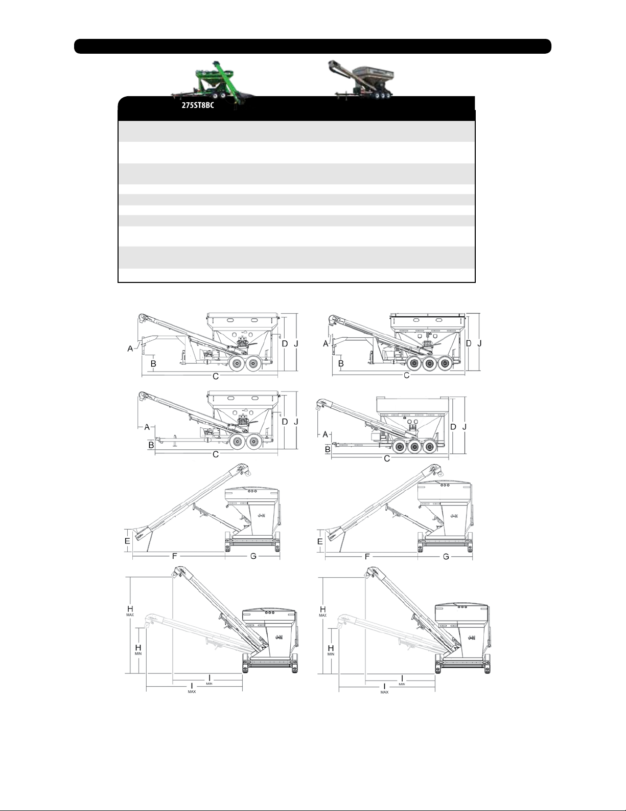
Specications
275ST8BC
with 8” Wide Tube Conveyor
A
A
B
B
C
C
D
E
F
G
H
I
J
5’
2’-10” (Gooseneck Option)
1’-6” (min) 1’-10” (max)
2’-7” (min) 3’-3” (max) Gooseneck Option
21’-3”
23’-6” (Gooseneck Option)
9’-5”
4’-0”
18’-1”
8’-6”
15’-4” (max)
7’-5” (min)
17’-2” (max)
13’-4” (min)
10’-0”
375ST8BC
w/ 8” Tube Conveyor
4’-10”
2’-7” (Gooseneck Option)
1’-6” (min) 1’-10” (max)
2’-7” (min.) 3’-3” (max.) Gooseneck Option
22’-3”
24’-4” (Gooseneck Option)
9’-10”
4’-0”
15’-10”
8’-6”
15’-2” (max)
6’-10” (min)
17’-7” (max)
13’-6” (min)
10’-7”
5
Page 6

General Information
TO THE OWNER:
The purpose of this manual is to assist you in operating and maintaining your seed tender in a safe
manner. Read it carefully. It furnishes information and instructions that will help you achieve years of
dependable performance and help maintain safe operating conditions. If this machine is used by an
employee or is loaned or rented, make certain that the operator(s), prior to operating:
1. Is instructed in safe and proper use.
2. Reviews and understands the manual(s) pertaining to this machine.
Throughout this manual, the term IMPORTANT is used to indicate that failure to observe can cause
damage to equipment. The terms CAUTION, WARNING and DANGER are used in conjunction with the
Safety-Alert Symbol, (a triangle with an exclamation mark), to indicate the degree of hazard for items of
personal safety. When you see this symbol, carefully read the message that follows and be alert to the
possibility of personal injury or death.
This Safety-Alert symbol indicates a hazard and means
ATTENTION! BECOME ALERT! YOUR SAFETY IS INVOLVED!
DANGER
WARNING
CAUTION
IMPORTANT
Indicates an imminently hazardous situation that, if not avoided, will
result in death or serious injury.
Indicates a potentially hazardous situation that, if not avoided, could
result in death or serious injury, and includes hazards that are exposed
when guards are removed.
Indicates a potentially hazardous situation that, if not avoided, may result
in minor or moderate injury.
Indicates that failure to observe can cause damage to equipment.
NOTE
Indicates helpful information.
SAFETY RULES:
ATTENTION! BECOME ALERT! YOUR SAFETY IS INVOLVED!
Safety is a primary concern in the design and manufacture of our products. Unfortunately, our eorts to provide safe equipment
can be erased by an operator’s single careless act. In addition, hazard control and accident prevention are dependent upon the
awareness, concern, judgment, and proper training of personnel involved in the operation, transport, maintenance and storage of
equipment.
Make certain that the operator(s), prior to operating is instructed in safe and proper use and reviews and understands the
manual(s) pertaining to this machine. Also make certain that the operator(s) reviews and understands the operator’s manual of
the tow vehicle prior to hooking up or operating the Speed Tender.
Read this manual before you operate this machine. If you do not understand any part of this manual, or need more information,
contact the manufacturer or your authorized dealer.
Safety Rules Next Page
6
Page 7

Safety Rules
Understand that your safety and the safety of other persons are measured by how you service and operate this machine. Know the
1.
positions and functions of all controls before you try to operate them. Make sure to check all controls in a safe area before starting your
work.
The safety information given in this manual does not replace safety codes, federal, state, or local laws. Make certain your machine has
2.
the proper equipment as designated by local laws and regulations.
A frequent cause of personal injury or death is from persons falling o equipment and being run over. Do not permit persons to ride
3.
on this machine.
Secure Speed Tender safety chain to towing vehicle before transporting. Do not transport without safety chains being attached to tow
4.
vehicle.
Make sure that the conveyor is fastened securely to the boom arm, and the boom arm is resting on the boom arm support with lynch
5.
pin in place before transport.
Use good judgment when transporting Speed Tender on a highway. Maintain complete control at all times. Regulate speed to road
6.
conditions. Do not transport unit with rear compartment full and front compartment empty. The unit may not be properly balanced,
osetting the tongue weight of the Speed Tender.
When transporting on public roads, the conveyor must be in the forward position to meet with lighting and visibility marking requirements.
7.
Do not travel faster than 10 m/h. during o highway travel. Drive slowly over rough ground, hill sides, and around curves to avoid tipping.
8.
Use extreme care when operating close to ditches, fences, or on hillsides.
Use care when moving or operating Speed Tender near electric lines as serious injury or death can result from contact.
9.
Never adjust, service, clean, or lubricate Speed Tender until all power is shut o and the battery is disconnected. Keep all safety shields
10.
in place.
Carbon monoxide can cause severe nausea, fainting, or death. Do not operate engine in closed or conned work area.
11.
Explosive fuel can cause res and severe burns. Stop engine before lling fuel tank.
12.
Hot parts can cause severe burns. Do not touch engine while operating or just after stopping.
13.
Hydraulic oil leaking under pressure can penetrate skin and cause infection or other injury.
14.
To prevent personal injury when working with hydraulic power unit:
15.
a. Relieve all pressure before disconnecting uid lines.
b. Before applying pressure, make sure all connections are tight and components are in good condition.
c. Never use your hand to check for suspected leaks under pressure. Use a piece of cardboard or wood for this purpose.
Make sure that everyone is clear of equipment before applying power or moving the Speed Tender.
16.
Before lling the Speed Tender, make certain that no one is inside the grain tanks. Never allow children or anyone in, near, or on the
17.
Speed Tender during transport or during loading and unloading of grain. Be aware that moving grain is dangerous and can cause
entrapment, resulting in severe injury or death by suocation.
Before unhooking the Speed Tender from the transport vehicle, be sure to properly block the wheels to prevent the Speed Tender from
18.
moving.
19.
When using the Conveyor Swing option be sure to stand clear of the swinging boom arm at all times.
7
Page 8
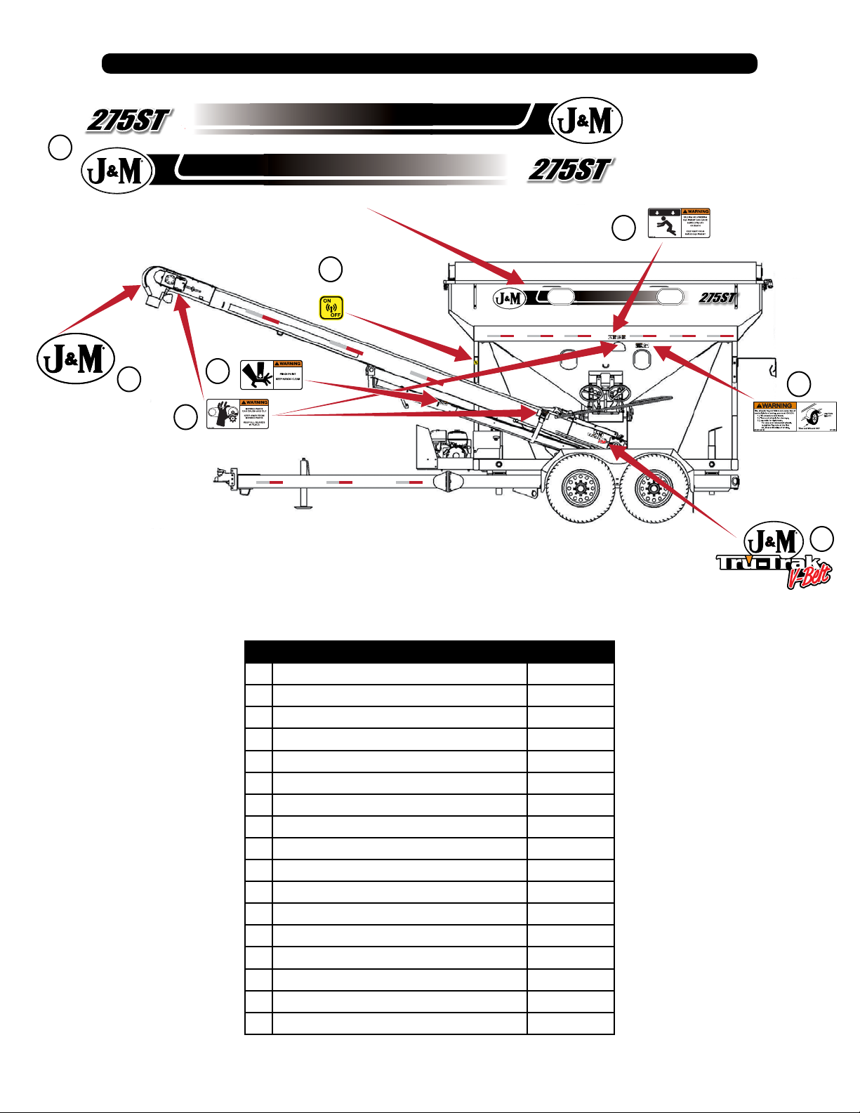
Decals
1
6
3
2
* Model 275 Shown
4
7
5
8
# Description Part #
1 Stripe Kit Specify Model
2 J&M Oval Decal Medium JM0010179
3 On/O Decal JM0014974
4 Warning, Pinch Point Decal JM0014994
5 Warning, Moving Parts Decal JM0014993
6 Warning, Falling/Lowering Decal JM0014992
7 Warning, Lug Nuts Tight? Decal JM0014996
8 J&M Oval Tru-Trak Decal JM0037730
9 Danger, Flowing Grain Traps ST Decal JM0014969
10 Warning, Shut o Power Before Service JM0018040
11 Speed Tender Decal JM0015002
12 J&M Oval Decal Large JM0015151
13 Warning, High Pressure Fluid Decal JM0010163
14 Warning, Keep Open Flames Away Decal JM0014983
15 Run Engine At Full Throtle To Charge Battery JM0032425
16 Danger, Electric Lines JM0015099
17 www.jm-inc.com JM0019239
8
Page 9
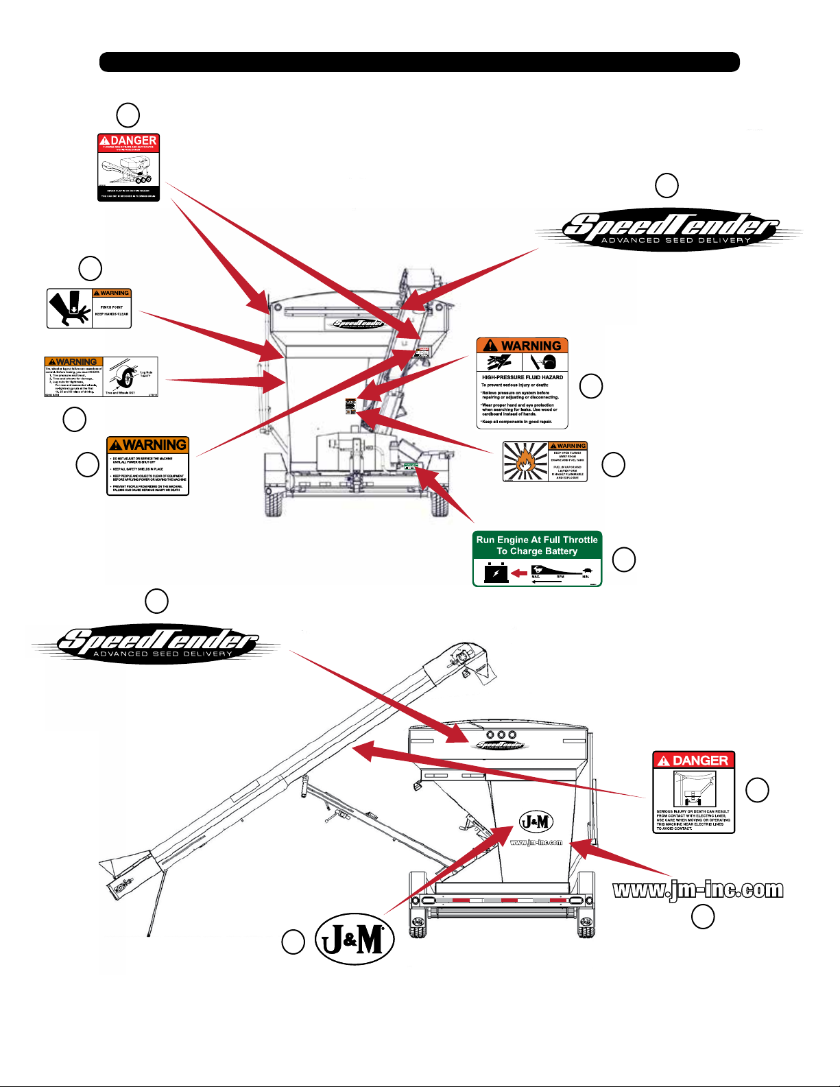
Decals
9
11
4
13
7
10
11
14
15
16
17
12
9
Page 10

1.0 Operations
1.1 Preparing the Towing Vehicle
Before towing the Speed Tender, refer to towing vehicle’s owner’s manual for information concerning hitch capacities, hitch
adjustments, and tire ination.
Towing vehicle must be equipped with proper electric braking components.
NOTE: The Speed Tender is equipped with LED lights. The towing vehicle may require a
asher upgrade for lights to operate properly.
Do not exceed towing vehicles GVWR (Gross Vehicle Weight Rating) or GCWR (Gross Combination Weight Rating), or the maximum
hitch load.
1.2 Preparing Speed Tender
Hydraulics: Check routing of all hydraulic hoses. Hoses should not be kinked, twisted or rubbing against sharp edges. Check all
hoses and ttings for hydraulic leaks. Tighten and /or repair or replace as required.
Lubrication: Lubricate Speed Tender as outlined in Service section 2.1. Refer to engine manual for proper uid levels in engine.
Tires/Wheels: Check tire pressures and maintain at recommended operating pressure. It is important to check wheel nut/bolts for
proper torque as recommended. You can nd proper tire pressure and wheel torque located in service manual section.
1.3 Connecting Speed Tender to the Towing Vehicle
WARNING: Do not stand between the Speed Tender and tow vehicle when hooking up.
NOTE: The Speed Tender comes standard with a 2 5/16” ball coupler and has an optional 3” lunette eye. Also the
Speed Tender can come with an optional Gooseneck Frame in place of the A-Frame. The Gooseneck Frame can
feature either a 2 5/16” ball coupler or a 5th Wheel hook up.
1. Back tow vehicle up to Speed Tender.
2. Align the vehicle’s ball or lunette eye with the coupler or ring on the Speed Tender.
3. Lift tongue latch lever.
4. Lower jack to set Speed Tender coupler down on ball or lunette eye hook.
5. Latch coupler and insert pin. Check to make sure that coupler is securely latched.
6. Pivot jack to transport position and pin in place.(A-Frame) Raise the “drop leg” for gooseneck jack.
7. Attach 7-way plug to tow vehicle. Check the length of the Speed Tender 7-way to make sure that it is long enough to turn,
but not too long to touch the ground.
NOTE: Check to make sure that lights are in proper operating condition and repair or
replace if necessary.
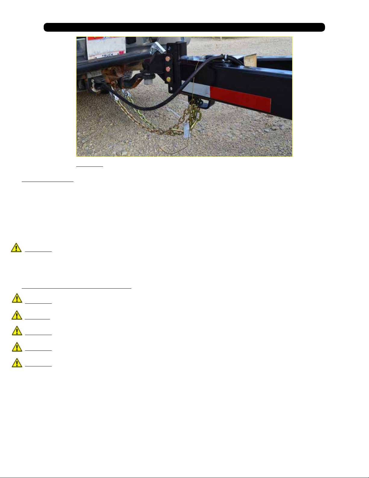
8. Connect the brake breakaway cable to towing vehicle.
9. Attach safety chains to tow vehicle by crossing chains (Figure 1.1). Allow enough slack in chains necessary for turning.
10. Test the brakes and all the lights on the Speed Tender
WARNING: Check safety chains for broken, stretched or damaged link or end ttings.
Replace chains if found to be damaged. Do not weld safety chains.
10
Page 11
1.0 Operations
Figure 1.1
1.4 Transporting
NOTE: Make sure the jack is in the horizontal position before transporting.
NOTE: Check to make sure the boom arm is in the boom rest and the lynch pin is in place
with the conveyor ratchet strap securely fastened.
NOTE: Make sure that the collapsible hopper is in the up position.
When transporting the Speed Tender on public roads, it is recommended to have the boom in the forward facing position. The
rearward facing position may not comply with state law for lighting and marking requirements.
WARNING: Travel at a safe speed that allows you to maintain complete control of towing vehicle and
Speed Tender at all times.
1.5 Hydraulic Power Unit Operation
WARNING: Explosive fuel can cause res and severe burns. Stop engine before lling fuel tank.
WARNING: Carbon monoxide can cause severe nausea, fainting or death. Do not operate engine in an enclosed or conned area.
WARNING: Hot parts can cause severe burns. Do not touch engine while operating or just after stopping.
WARNING: Acid from battery can cause res and severe acid burns. Make sure to charge battery in well-ventilated area.
WARNING: Make sure to relieve hydraulic pressure before working on hydraulic system.
11
Page 12
1.0 Operations
WARNING: Purge hydraulic system of air before operating Speed Tender to prevent serious injury or death.
WARNING: Wear proper hand and eye protection when searching for leaks. Use wood or cardboard instead of hands.
1. Check to make sure all ttings and hardware are in proper operating condition. Replace if worn or
broken. Check engine uid levels and sight gauge on reservoir for proper operating levels.
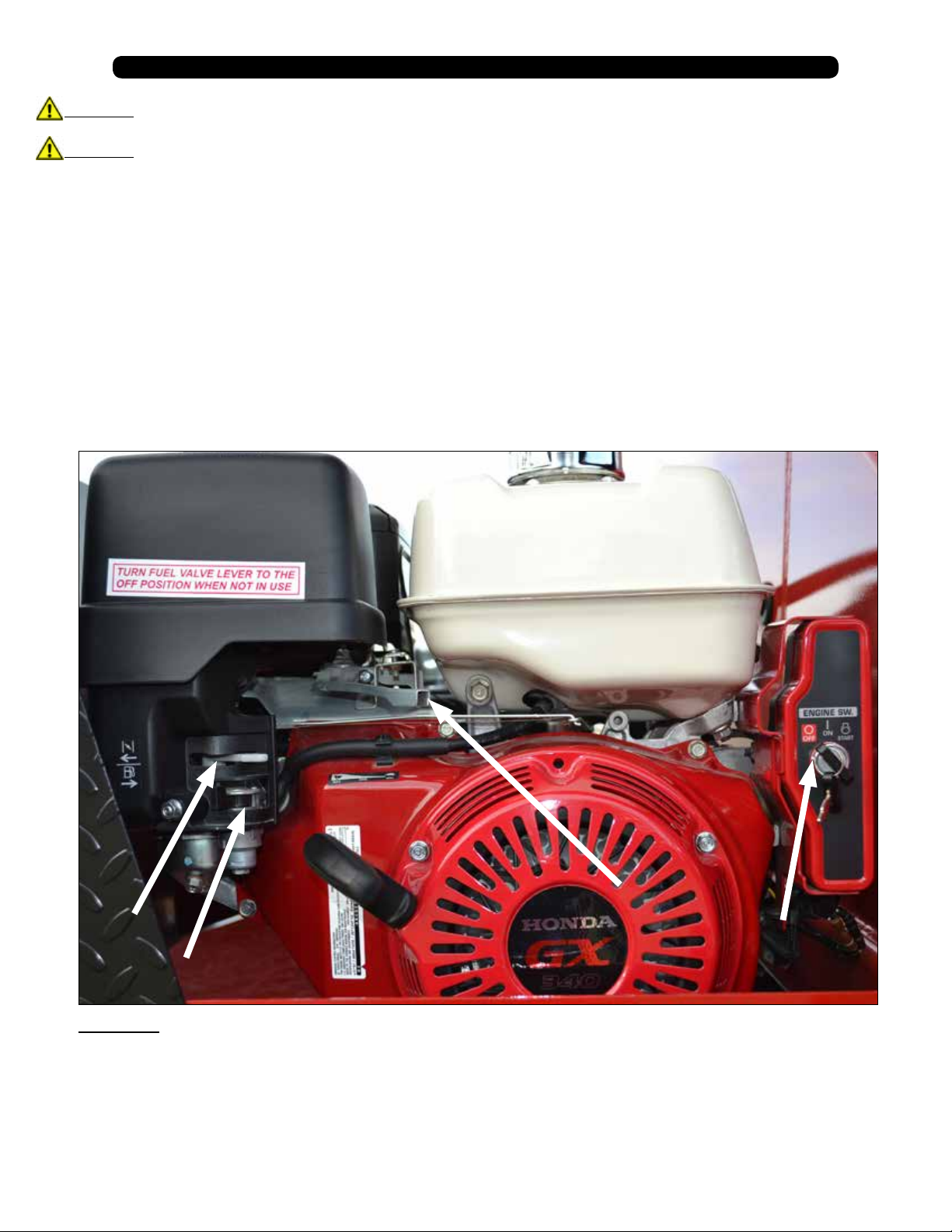
2. Slide the Fuel Shut-o Lever to the “ON” position (Figure 1.2).
3. Slide Choke Lever to the “ON” position (Figure 1.2).
4. Turn the key to the start position. Once engine starts, release key (Figure 1.2).
5. After starting, allow the engine to warm-up. Slide choke to the “OFF” position, and increase throttle speed (Figure 1.2).
6. To turn the engine o, slide the Fuel Shut-o to the “OFF” position (Figure 1.2).
7. Turn key o.
NOTE: In extremely cold weather, it is best to allow engine and hydraulics to warm-up before
increasing throttle speed.
NOTE: If a hydraulic leak appears, turn o immediately and take appropriate action.
NOTE: See Engine manual for more details on upkeep and service.
Choke
Fuel Shut-o
Figure 1.2
Throttle
Key
12
Page 13
1.0 Operations
1.6 Field Operation
WARNING: The Speed Tender must be hooked to the towing vehicle during loading and
unloading.
1. Position the Speed Tender next to the planter/drill so the conveyor will reach the planter box.
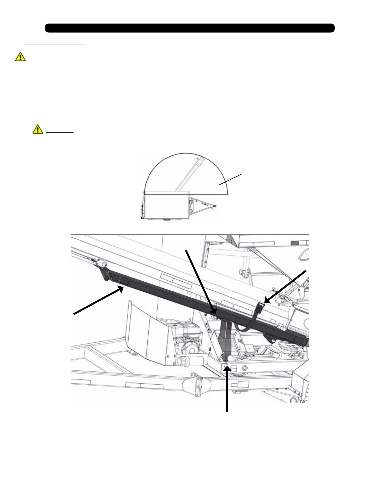
2. Remove lynch pin from Boom Arm. (Figure 1.3).
3. Start the hydraulic power unit and increase throttle speed. (Allow hydraulic uid to warm-up.)(Figure 1.2).
4. Raise the boom out of the Boom Rest using the handheld control (Figure 1.4).
NOTE: Wireless options feature a Wireless Remote (Figure 1.4).
WARNING: When operating the hydraulic swing option, Do not stand in the operating range of the Conveyer.
Operating Range
5. Check to make sure the hopper is in the up position (Figure 1.6)
Lynch Pin
Boom Arm
Hold-Down
Ratchet Strap
Figure 1.3
Boom Rest
13
Page 14
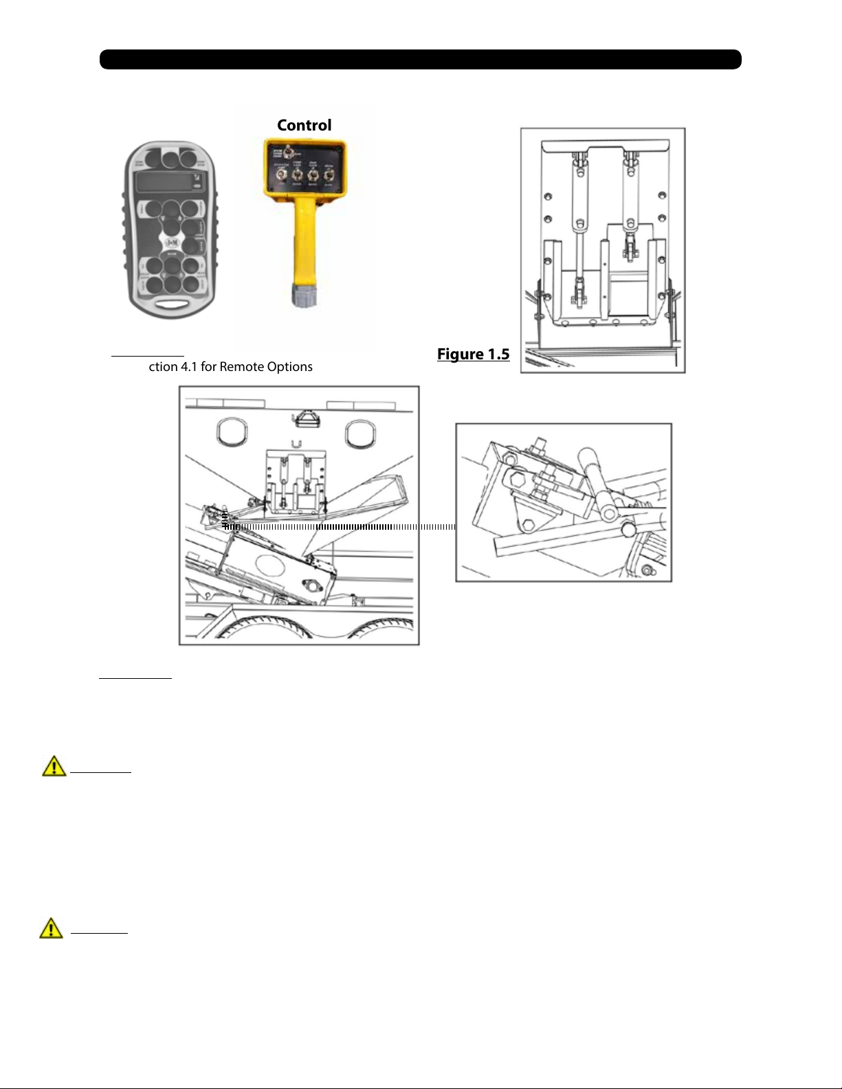
Wireless
Remote
Handheld
Control
1.0 Operations
Hydraulic
Door
Assembly
Figure 1.4
See Section 4.1 for Remote Options
Figure 1.5
Hopper Up
Figure 1.6
8. Open door on Speed Tender using supplied remote. (Figure 1.4).
WARNING: Empty-out the rear compartment rst to help prevent the chance of ipping the
Speed Tender.
9. Use the Handheld Control or Wireless Remote to start the conveyor.
10. Fill the planter/drill to desired level then repeat.
NOTE: Adjusting engine throttle will regulate conveyor speed.
11. Close door on Speed Tender before the last planter seed box is full so you can completely empty-out collapsible hopper
and conveyor.
CAUTION: If you are parked on an incline the boom arm may swing freely. (It is advised that you do not use the
Speed Tender on uneven ground).
14
Page 15
1.0 Operations
12. Position boom above boom rest and lower to allow its full weight on the boom rest.
13. Replace lynch pin in Boom Arm.
14. Make sure that the conveyor hold down ratchet strap is tight enough that the conveyor will not move
during transportation.
15. Make sure the collapsible hopper is in the up position for storage (Figure 1.6).
NOTE: If you are not using an optional hopper cover this will help the water drain out of the hopper.
16. The engine must throttle at, or above 80% throttle for 3 seconds to begin charge. After the 3 seconds at 80% throttle the
battery will continue to charge until the engine is turned o.
17. Slide the fuel shut o lever to the “OFF” position. This will allow the engine to shuto by running out of gas.
18. Turn the key to the “OFF” position.
1.7 Filling Speed Tender From Another Wagon or Bulk Container
WARNING: The Speed Tender must be hooked to the towing vehicle during loading and
unloading.
1. Remove lynch pin from Boom Arm (Figure 1.3).
2. Start the hydraulic power unit and increase throttle speed. (Allow hydraulic uid to warm up.)
NOTE: Make sure collapsible hopper is in the down position.
3. Raise the boom out of boom rest using the handheld control. (Figure 1.4).
NOTE: Wireless options feature a Wireless Remote (Figure 1.4).
CAUTION: If you are parked on an incline, the boom arm may swing freely. (It is advised
that you do not use Speed Tender on uneven ground)
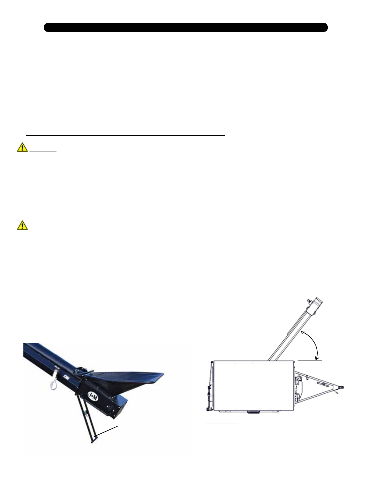
5. Rotate the conveyor to 45 deg. (Figure 1.8)
6. Lower the boom so you can remove the telescoping spout from the discharge end of the conveyor.
7. Undo the conveyor hold down ratchet strap (Figure 1.3).
8. Swing the collapsible hopper end out from under the Speed Tender shell.
9. Position the discharge end over the Speed Tender.
NOTE: The conveyor is equipped with a stand (Figure 1.7). (It is recommended for use whenever
possible to maximize conveyor performance and for easier access to discharge point on bulk seed
containers).
10. Lock the Boom Arm in place.
45 deg.
Figure 1.7
Conveyer Stand
Figure 1.8
15
Page 16

1.0 Operations
11. Lock collapsible hopper in the up position (Figure 1.6).
12. Position the wagon or bulk seed container over the collapsible hopper.
13. Use the handheld controller or wireless remote to start the conveyor.
14. Fill the Speed Tender to desired level.
WARNING: Fill the front compartment rst to help prevent the chance of ipping.
15. Run the conveyor until the collapsible hopper is empty.
16. When nished loading seed into the Speed Tender, move the wagon or bulk seed container away from conveyor.
17. Place collapsible hopper in the down position.
18. With the Boom Arm at a 45 deg. angle and locked, swing the conveyor back into the resting position on the boom arm Figure 1.8).
19. Place the conveyor hold down ratchet strap around the conveyor and tighten the strap (Figure 1.3).
CAUTION: If you are parked on an incline, the boom arm may swing freely. (It is advised that
you do not use the Speed Tender on uneven ground.)
20. Position boom arm above the boom rest and lower to allow its full weight on the boom rest.
21. Replace lynch pin in boom arm pin.
22. Make sure that the conveyor hold down ratchet strap is tight enough that the conveyor will not move during transport.
23. Make sure the collapsible hopper is in the up position for storage (Figure 1.6).
NOTE: This will help the water drain out of the hopper.
24. The engine must throttle at, or above 80% throttle for 3 seconds to begin charge. After the 3 seconds at 80% throttle the
battery will continue to charge until the engine is turned o.
25. Slide the fuel shut o lever to the “OFF” position. This will allow the engine to shuto by running out of gas.
26. Turn the key to the “OFF” position.
1.8 Cleaning out Collapsible Hopper and Conveyer
WARNING: The Speed Tender must be hooked to the towing vehicle during loading and
unloading.
1. Remove lynch pin from Boom Arm (Figure 1.3).
2. Start the hydraulic power unit and increase throttle speed. (Allow hydraulic uid to warm up if it is cold outside) (Figure 1.2).
NOTE: Make sure collapsible hopper is in the down position.
3. Raise the boom out of boom rest using the handheld control. (Figure 1.4).
NOTE: Wireless options feature a Wireless Remote (Figure 1.4).
4. Move the boom lock handle to the unlock position. This will allow the boom to swing (Figure 1.3).
CAUTION: If you are parked on an incline, the boom arm may swing freely. (It is advised
that you do not use Speed Tender on uneven ground).
5. Rotate the conveyor to 45 deg. (Figure 1.8).
16
Page 17
1.0 Operations
6. Lower the boom so you can remove the telescoping spout from the discharge end of the conveyor.
7. Undo the conveyor hold down ratchet strap (Figure 1.3).
8. Swing the collapsible hopper end out from under the Speed Tender shell.
9. Place the collapsible hopper in the up position (Figure 1.6)
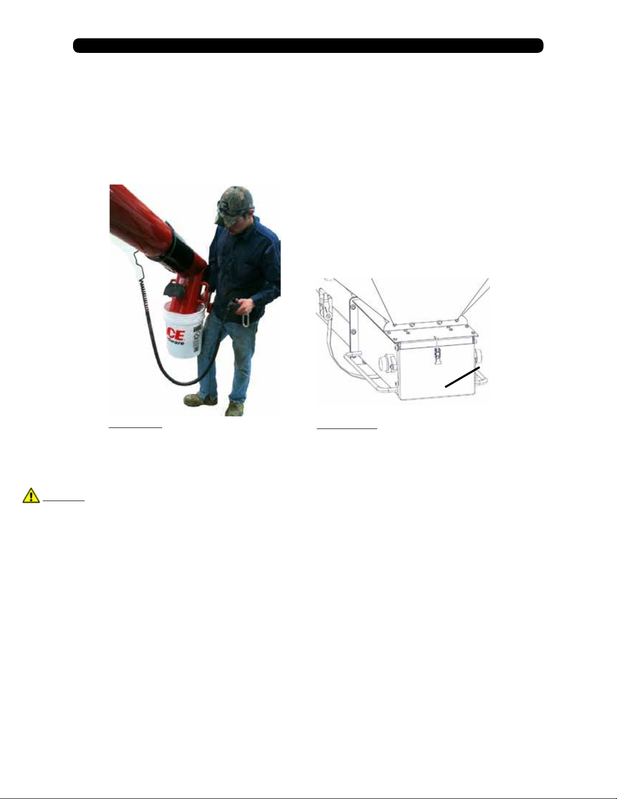
10. With the discharge end lower than the collapsible hopper end, place the discharge end into a 5 Gal. bucket
(Figure 1.9). Using the hand held controller, start the conveyor and run until completely empty.
11. Lower the collapsible hopper end back down to the ground. This will allow you to open the clean-out door.
(Figure 1.10)
Conveyer Clean-
out Door
Figure 1.9
12. Place collapsible hopper in the down position.
CAUTION: If you are parked on an incline, the boom arm may swing freely. (It is advised that you do not use
Speed Tender on uneven ground).
13. With the boom arm at a 45 Deg. angle, swing the conveyor back into the resting position on the
boom arm (Figure 1.8).
14. Place the conveyor hold down ratchet strap around the conveyor and tighten the strap
(Figure 1.3).
15. Position boom arm above boom rest and lower to allow its full weight on the boom rest.
16. Replace lynch pin in boom pin.
17. Make sure that the conveyor hold down ratchet strap is tight enough that the conveyor will not move during transportation.
18. Make sure the collapsible hopper is in the up position for storage (Figure 1.6).
NOTE: This will help the water drain out of the hopper.
19. Slide the fuel shut o lever to the “OFF” position. This will allow the engine to shuto by running out of gas.
20. Turn the key to the “OFF” position.
Figure 1.10
17
Page 18
1.0 Operations
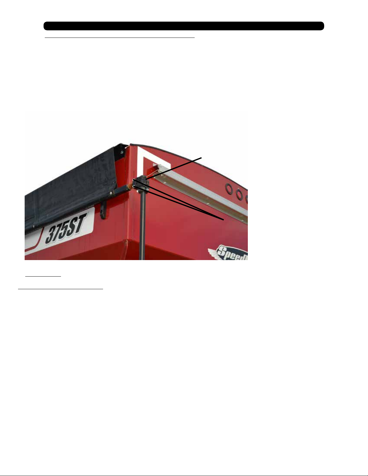
1.9 Adjusting the Tarp Tension in Hanger Bracket
1. Fully unroll the tarp as shown in Figure 1.11.
2. Remove the two bolts that hold the tarp U-Joint on the splined shaft.
3. Remove the u-joint from the spline shaft.
4. Rotate u-joint and handle three or four spline teeth.
NOTE: Clockwise to tighten the tarp or counter-clockwise to loosen it.
5. Slide the u-joint and handle back onto the spline shaft.
6. Replace and tighten the two bolts.
U-Joint
Bolts
*Same for both the 275 & 375 Speed Tenders.
Figure 1.11
1.10 Basic Scale Operations
1. Turn the scale “ON” by pressing the on/o button. The display shows “Hello” then the current weight value is displayed.
2. Press G/N to access the gross mode. (Live scale weight is displayed in the G/N weighing mode.)
3. In the gross mode, press the ZERO/CLEAR key to zero the indicator when the Speed Tender is empty.
4. After initial amount is placed on the scale, press the TARE Key. (Weight is tarred o and goes into net mode, showing
weight).
5. Load or unload material as needed (Shows + when loading and a – value when unloading).
6. When the display reaches the proper amount, stop loading or unloading.
7. Repeat steps 2 through 4 until complete.
NOTE: For more information, refer to the scale manual.
18
Page 19

2.0 Service
2.1 Grease Conveyer Bearings
Grease the conveyor bearings every 10 hours of operation and before storage. Use only two pumps of grease per bearing (Figure 2.1).
NOTE: Over lubrication of these bearings will result in premature failure.
NOTE: The conveyor has four bearings that need grease (two at each end).
Grease Point
2.2 Grease Boom Arm
Grease pivot points on boom arm every 50 hours and before storage (Figure 2.2).
Figure 2.1
Grease Points
Figure 2.2
19
Page 20

2.0 Service
2.3 Tire Pressure
The following is to be used as a general guide for tire ination. Figures can vary depending on specic brand of tire used. It is important that tires are inspected before and after unit is loaded. Start with the minimum pressure indicated. The tire should stand up
with no side wall buckling or distress as tire rolls. Do not exceed maximum recommended tire pressure. 80 psi is the cold rating on
the tire that is standard for the Speed Tender. J&M also recommends to rotate your tires front to back (not side to side) every 1,200
miles or 12 months (whichever comes rst) for longer tire life. Figure 2.3 below is a troubleshooting chart used to ensure the tires
wear evenly.
Figure 2.3
2.4 Tightening Lugnuts
Torque lug-nuts on new and removed wheels to 220 ft. lbs. after the rst 10, 25, and 50 miles of driving, then recheck torque every
50 hours or every year, whichever comes rst.
20
Page 21

2.0 Service
2.5 Wheel Bearings
The wheel bearings need to be cleaned, inspected, and repacked every 12 months or 12,000 miles. Use a number 2 wheel bearing
grease to repack the bearings.
Bearing Inspection and Service:
1. Jack up Speed Tender.
2. Remove wheel lug-nuts.
3. Remove wheel from hub.
4. Remove grease cap.
NOTE: Be careful not to dent or cut a hole in grease cap.
5. Remove the cotter pin, nut, and washer.
6. Wiggle the hub to take the outer wheel bearing out.
7. Pull hub assembly straight o the axle. If you want to reuse the grease seal, (which is not recommended), be careful to
support the weight of the hub so that the end of the axle does not ruin the rubber part of the grease seal.
8. To remove the inner bearing, you must remove the grease seal.
9. Remove inner bearing.
10. Wash all grease and oil from the bearing cone using a suitable solvent. Dry the bearing with a clean, lint- free cloth and
inspect each roller completely. If any pitting, scalding, or corrosion is present, then the bearing must be replaced.
The bearing cups inside the hub must be inspected.
NOTE: Bearings must always be replaced in sets of a cone and a cup (See bearing cup replacement on following
page.)
11. Repack inner bearing with new grease.
A. Place a moderate amount of grease in the palm of one hand.
B. Hold the inner bearing, large side down, in your other hand
C. Using the edge of the bearing like an ice-cream scoop, work it in until you see fresh grease
come out of the top side of the bearing.
D. Rotate 1/8 of a turn and repeat until the whole bearing is full of fresh grease.
12. Place the inner bearing in the back of the wheel hub and add a liberal dose of grease.
13. Position the new wheel seal in its recess and lightly set it with a hammer.
NOTE: Be careful to not deform the metal part of the seal.
14. Slide the hub assembly onto the spindle and push it back into position.
15. Grease the outer bearings by hand. (See step 11)
16. Slide it and the spindle washer onto the spindle and into the hub recess.
17. Install and bottom out the spindle nut, then back it o 1/4 turn.
18. Reinstall the spindle nut and replace the cotter pin with a new one.
NOTE: If the castle nut does not line up with the hole in the spindle, then loosen the nut
slightly until it does.
19. Pack the bearing cap with fresh grease and lightly drive it into the hub recess with a hammer.
20. Reinstall the wheel onto the hub and torque the wheel lug-nuts.
NOTE: See wheel nut/bolt torque requirements located in section 2.4.
Bearing cup replacement:
1. Place the hub on a at work surface with the cup to be replaced on the bottom side.
2. Using a brass drift punch, carefully tap around the small diameter end of the cup to drive it out.
3. After cleaning the hub bore area, replace the cup by tapping it with the brass drift punch. Be sure the cup is seated all the
way up against the retaining shoulder in the hub.
21
Page 22

2.0 Service
2.6 Hydraulic Power Unit
Daily (every 5 hours of use):
1. Check oil level.
2. Inspect for oil leaks and repair as necessary.
3. Check all hoses, ttings, bolts and hardware to make sure that they are secure and properly tightened.
4. Check motor oil level. See Engine operator’s manual for details on oil levels, oil types, and service
intervals.
Once per season (every 20-25 hours of use):
Change hydraulic oil lter element with either a NAPA 155Z or a FRAM P1654A Filter.
Every two to three years (every 75-80 hours of use):
Drain oil reservoir and rell with clean, good quality hydraulic AW 32 oil. (It is not recommended to rell with tractor
hydraulic oil).
Replacing hydraulic parts:
Check parts section for proper part description and part # for replacement.
Purge air from system as follows:
1. Disconnect the rod end clevis of all cylinders in a circuit and block up cylinders so the rod can completely extend and
retract without contacting any other components.
2. Pressurize the system and maintain system at full pressure for at least 5 sec. after cylinder rods stop
moving. Check that all cylinders have fully extended or retracted.
3. Check hydraulic reservoir and rell as needed.
4. Pressurize system again to reverse the motion of step 2. Maintain pressure on system for at least 5 sec.
after cylinder rods stop moving. Check that cylinders have fully extended or retracted.
5. Check for hydraulic leaks using cardboard or wood. Tighten connections according to the torque chart. (pg.28)
6. Repeat steps 2, 3, 4 and 5 (3 to 4 times).
7. Depressurize hydraulic system and connect cylinder rod clevises to their mating lugs.
2.7 Conveyer Belt Tracking
Conveyor belt must run in the center of the pulley at both the discharge end and the collapsible hopper end. Failure to do so will
lead to unnecessary wear and shortening of belt life. We recommend that you check your belt for proper tracking every 10 hours of
use and before every season.
Checking the belt tracking at collapsible hopper end:
1. Open clean out-door located under collapsible hopper (Figure 2.4). This will allow you to see if the belt is centered on the pulley.
2. If the tracking is ok, close the clean out-door. If tracking is o, see (Section 2.8).
Checking the belt tracking at discharge end:
1. Remove the 12 bolts located at the discharge end (Figure 2.4).
2. Remove the Discharge Pan and Rubber Discharge Pan. This will allow you to see if the belt is centered on the pulley.
3. If the belt tracking is good, reinstall the head pan. If tracking is o, see Section 2.8.
22
Page 23

Discharge Pan
Bearing Mounting
Plate
Jam Nut
Remove
2.0 Service
Remove
Adjustment Bolt
Loosen these
bolts when adjusting belt
tension. Typical each side.
Figure 2.4
Conveyer
Clean-out Door
A
B
2.8 Adjusting Conveyer Belt Tracking
1. Loosen (Do Not Remove) the 4 bolts on the two bearing mounting plates located at the collapsible hopper end of the
conveyor (Figure 2.5). NOTE: Only adjust conveyor in normal position, do not adjust in self-ll position.
2. Operate the conveyor at a slow speed.
CAUTION: Keep hands and clothing away from moving parts.
3. Loosen jam nut on adjustment bolt (Figure 2.5).
4. Tighten the adjustment bolt slowly until belt is running in the center of the pulley.
NOTE: Do not loosen the Adjustment bolt.
5. Tighten all bolts on bearing mounting plate, and adjustment bolts jam nuts.
6. Repeat at discharge end.
7. When belt is running in center of the pulley on both ends of conveyor, allow the Speed Tender to run for 10 min, and
recheck belt for proper tracking.
Jam Nut
Measurments A & B need to be the same.
Bearing Mounting
Plate
Figure 2.5
Adjustment Bolt
Jam Nut
Loosen these
bolts when adjusting belt
tension. Typical each side.
23
Page 24

2.0 Service
2.9 Belt Tensioning
NOTE: You need to adjust your belt tension at least once a year.
1. Remove the head pan and head pan gasket (Figure 2.3).
2. Loosen (Do Not Remove) the 4 bolts on the two bearing mounting plates located at the discharge end of the conveyor
(Figure 2.3).
3. Loosen jam nut on adjustment bolt at discharge end (Figure 2.3).
4. Torque threaded adjustment bolt to 23 ft-lb.
5. Operate the conveyor at a slow speed.
CAUTION: Keep hands and clothing away from moving parts.
6. If the belt is tracking properly go to step 7. If tracking is o, see Section 2.8.
7. Open the clean-out door located under collapsible hopper (Figure 2.4). This will allow you to see if the belt is centered on
the pulley.
8. If the tracking is ok, close the clean-out door, tighten all hardware and go to step 9. If tracking is o, see Section 2.8.
9. Run the belt at medium speed for 10 min. and recheck the tracking at both the discharge and collapsible hopper end.
10. If tracking is o, see section 2.8.
11. If the belt is still tracking in the center of both pulleys, reinstall the head pan.
2.10 Electric Brakes
The Speed Tender is equipped with electric brakes. They need to be inspected and serviced immediately if a loss of performance is
experienced. You need to service your Speed Tender brakes at least once a year with normal use.
How to use your electric brakes properly:
Your Speed Tender brakes are designed to work in synchronization with your tow vehicle brakes. Never use your tow vehicle or Speed
Tender brakes alone to stop the combined load.
Your Speed Tender and tow vehicle will seldom have the correct amperage ow to the brake magnets to give you comfortable, safe
braking unless you make proper brake system adjustments. Changing trailer load and driving conditions, as well as uneven alternator
and battery output, can mean unstable current ow to your brake magnets. It is therefore imperative that you maintain and adjust
your brakes as set forth in this manual, use a properly modulated brake controller, and perform the synchronization procedure noted
below.
In addition to the synchronization adjustment detailed below, electric brake controllers provide a modulation function that varies
the current to the electric brakes with the pressure on the brake pedal or amount of deceleration of the tow vehicle. It is important
that your brake controller provide approximately 2 volts to the braking system when the brake pedal is rst depressed and gradually
increases the voltage to 12 volts as brake pedal pressure is increased. If the controller “jumps” immediately to a high voltage output,
even during a gradual stop, then the electric brakes will always be fully energized and will result in harsh brakes and potential wheel
lockup.
To synchronize:
To insure safe brake performance and synchronization, read the brake controller manufacturer’s instruction completely before preforming the synchronization procedure.
Make several hard stops from 20 m/h on a dry paved road that is free of sand and gravel. If the Speed Tender brakes lock and slide,
decrease the gain setting on the controller. If they do not slide, slightly increase the gain setting, Adjust the controller just to the point
of impending brake lockup and wheel skid.
24
Page 25

2.0 Service
How to adjust electric brakes:
1. Park the Speed Tender on rm and level ground.
2. Block the trailer tires on the opposite side securely so that no forward or rearward movement is possible.
3. Jack up the Speed Tender.
4. Secure the trailer on jack stands of adequate capacity front and rear.
5. At the back of the wheel, on the brake backing plate, there is a small rubber plug near the bottom of the backing plate.
Pry out this plug to give access to the star wheel adjuster.
6. Insert the brake adjuster tool and maneuver it so that the tool engages with the teeth in the star wheel. The star wheel
looks like a gear with exposed teeth on the perimeter.
7. Turn the adjuster until the brake locks up (you can no longer rotate the wheel by hand). This centers the brake shoes on
the brake drum so that they are in the correct position.
8. Now back o the star wheel 8 to 10 clicks or as specied by the manufacturer. The wheel should spin freely with no
apparent drag to slow it down. A slight scraping noise is normal as the wheel turns.
9. Repeat this procedure for all the wheels.
When to adjust brakes:
1. After the rst 200 miles of operating when the brake shoes and drums have “seated.”
2. At 3,000 mile intervals or once a year, whichever comes rst.
Brake Cleaning and Inspection:
Your Speed Tender brakes must be inspected and serviced at yearly intervals, (or more often as use and performance requires).
Magnets and shoes must be changed when they become worn or scored thereby preventing adequate vehicle braking. Clean the
backing plate, magnet arm, magnet, and brake shoes. Make certain that all the parts removed are replaced in the same brake and
drum assembly. Inspect the magnet arm for any loose or worn parts. Check shoe return springs, hold down springs, and adjuster
springs for stretch or deformation and replace if required.
Brake Shoe and Lining Inspection:
A simple visual inspection of your brake linings will tell if they are usable. Replacement is necessary if the lining is worn (to within
1/16” or less), contaminated with grease or oil, or abnormally scored or gouged. Hairline heat cracks are normal in bonded linings
and should not be cause for concern (Figure 2.6). When replacement is necessary, it is important to replace both shoes on each brake
and both brakes of the same axle. This will help retain the “balance” of your brakes.
Acceptable
Hairline Cracks
Figure 2.6
25
Page 26

2.0 Service
Replacing Brake Linings:
1. Remove the brake shoe retract spring.
2. Remove the shoe hold down assembly by holding the back of the pin with one hand and pushing against the spring and
twisting with a hold down spring tool until the cup is released.
3. Remove both shoes together leaving the adjuster assembly and spring intact.
4. Clean the backing plate and lever arm.
5. Inspect magnet arm for any loose or worn parts.
6. Replace springs that are broken, bent, or weak.
7. Apply a light lm of lubricant to the anchor pin and shoe rest pads & backing plate areas that are in contact with the lever arm.
8. Attach the adjuster screw and spring to the new brake shoes. The star wheel and adjuster must be
positioned as before.
9. Install the new shoes on the backing plate and reinstall shoe retract spring.
After replacement of brake shoes and linings, the brake must be re-burnished to seat in the new components. This should be done by
applying the brakes 20 to 30 times from an initial speed of 40 m/h, slowing the vehicle to 20 m/h. Allow ample time for brakes to cool
between applications. This procedure allows the brake shoes to seat into the drum surface.
Brake Lubrication:
Before reassembling, apply a light lm of lubrication or similar grease, or anti-seize compound on the brake anchor pin, the actuating
arm bushing and pin, and the areas of the backing plate that are in contact with the brake shoes and magnet lever arm. Apply a light
lm of grease on the actuating block mounted on the actuating arm.
Troubleshooting:
Most electric brake malfunctions that cannot be corrected by either brake adjustments or synchronization adjustments can generally
be traced to electrical system failure. Mechanical causes are ordinarily obvious, bent or broken parts, worn out linings or magnets,
seized lever arms or shoes, scored drums, loose parts, etc. Voltmeter and ammeter are essential tools for proper troubleshooting of
electric brakes.
How to Measure Voltage:
System voltage is measured at the magnets. Connect the voltmeter to the two magnet lead wires at any brake. This may be accomplished by using a pin probe inserted through the insulation of the wires dropping down from the chassis or by cutting the wires. The
engine of the towing vehicle should be running when checking the voltage (so that a low battery will not aect the readings).
Brake Magnet Inspection:
Your electric brakes are equipped with high quality electromagnets that are designed to provide the proper force and friction. Your
magnets should be inspected and replaced if worn unevenly or abnormally (Figure 2.7). Even if wear is normal as indicated by your
straightedge, the magnets should be replaced if any part of the magnet coil has become visible through the friction material facing
of magnet. It is also recommended that the drum armature surface be re-faced when replacing magnets. Magnets should also be
replaced in pairs - both sides of an axle.
26
Page 27

2.0 Service
Straight Edge
Abnormal Wear
Normal Wear
(Replace)
Figure 2.7
Voltage in the system should begin at 0 volts. As the controller bar is slowly actuated, the voltage should gradually increases to
about 12 volts. This is referred to as modulation. No modulation means that when the controller begins to apply voltage to brakes
it applies an immediate high voltage, which causes the brakes to apply instantaneous maximum power.
The threshold voltage of a controller is the voltage applied to the brakes when the controller rst turns on. The lower the threshold
voltage, the smoother the brakes will operate. Threshold voltage in excess of 2 volts (quite often found in heavy duty controllers)
can cause grabbing, resulting in harsh braking.
How to Measure Amperage:
System amperage is the amperage being drawn by all brakes on the trailer. The engine of the towing vehicle should be running
when checking amperage.
One place to measure system amperage is at the blue wire of the controller which is the output to the brakes. The blue wire must
be disconnected and the amp meter put in series into the line. System amperage draw should be as noted in the table below. Make
sure your ammeter has sucient capacity and note polarity to prevent damaging your amp meter.
Brake Size Amps/Magnet Two Brakes Four Brakes Six Brakes Magnet Ohms
12 X 2 3.0 6.0 12.0 18.0 3.2
Replacing brake magnet
1. Orient the magnet over the lever arm post such that the magnet leads are in the correct position for routing.
2. Push the magnet over the lever arm post by compressing the magnet spring between the magnet and the lever arm.
3. Insert the magnet clip in the slot of the magnet. Be sure to orient the magnet clip so it will “snap” into place.
4. Press down on the magnet and install the magnet clip.
5. Be sure that the magnet moves up and down freely on the lever arm post.
6. Route the wiring in the same manner noted on removal. Be sure that wires cannot bind, pinch, or rub. Manually actuate
lever arm to insure there is no interference.
7. Install strain relief bushing, allowing enough slack in the wiring to allow the lever arm to move without straining the
wires. Be sure the wire cannot come in contact with the armature.
8. Connect the magnet leads to the trailer wiring harness and then reinstall hub and drum.
27
Page 28

2.0 Service
Brake Drum Inspection:
There are two areas of the brake drum that are subject to wear and require inspection. These two areas are the drum surface where the
brake shoes make contact during stopping and the armature surface where the magnet contacts (only in electric brakes).
The drum surface should be inspected for excessive wear or heavy scoring. If worn more than .020” oversized, or if the drum has worn
out of round by more than .015”, then the drum surface should be turned. If scoring or other wear is greater than .090” on the diameter,
the drum must be replaced. When turning the drum surface, the maximum re-bore diameter for a 12” brake drum is 12.090”
The machined inner surface of the brake drum that contacts the brake magnet is called the armature surface. If the armature surface is
scored or worn unevenly, it should be refaced to a 120 micro inch nish by removing not more than .030” of material. To insure proper
contact between the armature face and the magnet face, the magnets should be replaced whenever the armature surface is refaced
and the armature surface should be refaced whenever the magnets are replaced.
2.11 Daily Service (5 -10 Hours of Use)
NOTE: J&M recommends the following service to be performed daily (every 5-10 hours of use)
1. Grease the conveyor bearings every 10 hours. Use only two pumps of grease per bearing
NOTE: Over lubrication of these bearings will result in premature failure.
NOTE: The conveyor has 4 bearings that need greased (2 at each end)(See section 2.1).
2. Check your belt for proper tracking every 10 hours of use and before every season. For steps to properly track your belt see section 2.7.
NOTE: When checking the belt for tracking you should empty out the clean-out door (Figure 2.4).
3. Check hydraulic oil level.
4. Inspect for oil leaks and repair as appropriate.
5. Check all hoses, ttings, bolts, and hardware to make sure that they are secure and properly tightened.
6. Check engine oil level. See Engine operator’s manual for details on oil levels, oil types and service intervals.
7. Check Speed Tender breaks and lights before towing.
8. Check the Speed Tender periodically for cracks in welds and for other structural damage. Have cracked welds xed immediately.
NOTE: Failure to have cracked welds xed immediately could result in extensive damage to
the Speed Tender and greatly reduce its life.
9. Make sure tires are properly inated (See section 2.3).
10. Make sure wheel lug nuts are properly torqued (See section 2.4).
11. Make sure that the conveyor hopper guard is in place. Do not remove.
12. Clean out the Conveyor at the end of every day of use (Section 1.8).
2.12 End of the Year Service
IMPORTANT: When the Speed Tender is not going to be used for a length of time, J & M recommends that you store the
Speed Tender in a dry, protected place. Leaving your Speed Tender outside and open to the weather will shorten its life.
1. Grease the conveyor bearings. Use only two pumps of grease per bearing.
NOTE: Over lubrication of these bearings will result in premature failure.
NOTE: The conveyor has four bearing that need greased (two at each end).
2. Grease pivot points on boom arm before storage.
3. The wheel bearings need to be cleaned, inspected, repacked, and adjusted. Use a number 2 wheel bearing grease to repack the
bearings.
4. Inspect and service the brakes (magnets and shoes). They must be changed when they become worn or scored, thereby
preventing inadequate vehicle braking. Clean the backing plate, magnet arm, magnet, and brake shoes. Make certain that
all the parts removed are replaced in the same brake and drum assembly. Inspect the magnet arm for any loose or worn
parts. Check shoe return springs, hold down springs, and adjuster springs for stretch or deformation, replace as needed.
28
Page 29

2.0 Service
2.12 End of the Year Service(Continued)
5. Torque lug-nuts (Section 2.4).
6. Make sure that the tires are properly inated.
7. Remove all grain from inside the grain tanks.
8. Clean out the Conveyor at the end of every season (Section 1.8).
9. Tension and track the conveyor belt. (Section 2.7).
10. Check the Speed Tender periodically for cracks in welds and for other structural damage. Have cracked welds xed immediately.
NOTE: Failure to have cracked welds xed immediately could result in extensive damage to
The Speed Tender and greatly reduce its life.
11. Check hydraulic hoses for wear and replace if needed.
12. Make sure that the conveyor hopper guard is in place.
13. Remove battery from the Speed Tender and place in a cool dry place.
NOTE: Attaching a trickle charger to the battery will help ensure a long life for your battery.
IMPORTANT: Be sure to disconnect the scales from the battery before charging.
14. Change hydraulic oil lter element with either a NAPA 155Z or a FRAM P1654A Filter.
15. Top o hydraulic oil tank with good quality hydraulic AW 32 oil.
NOTE: If the Hydraulic Oil appears to be “Milky” in color it should be changed immediately. Otherwise, the Hydraulic
Oil should be changed every 2-3 years. If the environment is extremely dusty or dirty the Hydraulic Oil should be
changed more often.
15. Check motor oil level. See Engine operator’s manual for details on oil levels, oil types, and service intervals.
16. Retract all hydraulic cylinders to prevent the piston rods from rusting.
17. Touch-up spots where paint has been worn away (use good quality primer paint - especially before
applying graphite paint to the inside of the grain tank).
2.13 Removing From Storage
1. Grease the conveyor bearings. Use only two pumps of grease per bearing
NOTE: Over lubrication of these bearings will result in premature failure.
NOTE: The conveyor has four bearings that need greased (two at each end). (See section 2.1).
2. Grease pivot points on boom arm.
3. Torque lug-nuts (Section 2.4).
4. Make sure that the tires are properly inated.
5. Check your belt for proper tracking every 10 hours of use and before every season. For steps to properly track your belt (Section 2.7).
6. Check oil level.
7. Inspect for hydraulic oil leaks and repair as appropriate.
8. Check all hoses, ttings, bolts, and hardware to make sure that they are secure and properly tightened.
9. Check engine oil level. See Engine operator’s manual for details on oil levels, oil types, and service
intervals.
10. Check Speed Tender lights before each time you tow.
11. Make sure that the conveyor hopper guard is in place.
12. Reattach battery and check to make sure that it is fully charged.
IMPORTANT: Be sure to disconnect the scales from the battery before charging.
29
Page 30

2.0 Service
2.14 Troubleshooting
Problems Solutions
Unit sways during travel a. Check tire pressure.
b. Check tow vehicle for loosened hitch parts.
c. Check tow vehicle’s hitch height.
d. Reduce towing speed.
e. Check wheel lug-nuts.
f. Check wheel bearings for adjustment (See section 2.5).
Tires show excessive wear a. Check tire pressure.
b. Rotate tires. (See section 2.3)
c. Check wheel bearings for adjustment. (See section 2.5).
Wheel makes grinding or squeaking noise a. Service wheel bearings. (See section 2.5).
Noisy when brakes are being applying a. Properly adjust brakes.
b. Replace any weak or broken springs in brakes.
c. Replace the brake linings if excessively worn or contaminated
d. Check wheel bearings for adjustment (See section 2.5).
No Brakes a. Properly adjust brakes
b. Check for short in electric circuit
c. Replace any brake magnets that are worn or defective
Weak brakes a. Properly adjust brakes
b. Replace any excessively worn or contaminated linings.
c. Check for short in electric circuit
d. Replace bent backing plate
Dragging brakes a. Properly adjust brakes
b. Replace any weak or broken springs in brakes
Locking brakes a. Replace any weak or broken springs in brakes
b. Replace any excessively worn or contaminated linings
Grabbing brakes a. Replace any excessively worn or contaminated linings
Surging brakes a. Trailer is not adequately grounded
Belt is not moving - Hydraulic pump is not producing
sucient pressure or volume to belt motor.
Belt is not moving - Obstructed conveyer a. Make sure conveyor is not clogged
Belt has insucient output speed or R.P.M. - Hydraulic pump is
not producing sucient pressure or volume to belt motor.
Belt has insucient output speed or R.P.M. - Belt is slipping a. Adjust belt tension and tracking (See section 2.8).
a. Check for pinched or leaking hydraulic line
b. Allow hydraulic oil to warm up
c. Increase engine R.P.M.
d. Charge battery or plug in to tow vehicle
e. Hydraulic uid level low
f. Hydraulic lter clogged
g. Check for proper oil viscosity
h. Check hydraulic output pressure.
a. Check for pinched or leaking hydraulic lines.
b. Allow hydraulic oil to warm up
c. Increase engine R.P.M.
d. Hydraulic uid level low
e. Hydraulic lter clogged
f. Check for proper oil viscosity
g. Repair or replace worn out pump.
b. Check telescoping spout and conveyor for a clog.
c. Remove material from clean out door.
30
Page 31

2.0 Service
2.14 Troubleshooting
Problems Solutions
Belt has insucient output speed or R.P.M. - Air in
hydraulic system.
Belt has insucient output speed or R.P.M. - Leak in motor, valve
body, or bypass valves.
Excessive wear to belt edge - Tracking is o. a. Adjust belt tension and tracking (See section 2.8).
Excessive wear to belt edge - Rubber skirting is worn or out of place. a. Replace rubber skirting.
Boom arm will not move up or down - Engine R.P.M. slow. a. Increase engine R.P.M.
Boom arm will not move up or down - Hydraulic pump is not
producing sucient pressure or volume to hydraulic cylinder.
Hydraulic unit squeals a. Check sight glass on hydraulic unit reservoir and ll if necessary.
Hydraulic unit has poor performance at high R.P.M. a. Clean pressure relief in control valve or replace
a. Bleed air out of hydraulic system and ll reservoir (See section
2.6).
b. Look for leaking or cracked ttings.
a. Replace or repair motor, valve body, or bypass valves.
b. Check for proper oil viscosity.
c. Clean and lubricate the brake assemblies
b. Adjust rubber skirting.
a. Check for pinched or leaking hydraulic lines.
b. Allow hydraulic oil to warm up.
c. Increase engine R.P.M.
d. Hydraulic uid level low.
e. Hydraulic lter clogged.
f. Check for proper oil viscosity.
g. Check to see if hydraulic pump is worn out
h. Make sure battery is fully charged.
i. Check wiring to valve body and hydraulic pump
b. Run engine at reduced speed for 5-10 minutes to warm up oil.
c. Clean/replace ller cap/breather.
d. Clear obstruction in suction hose.
e. Replace plugged/dirty oil lter element.
b. Check sight glass on hydraulic unit reservoir and ll if necessary.
c. Replace plugged/dirty oil lter element
d. Charge Battery
31
Page 32

2.15 Bolt Torque Specications
Specications
2.0 Service
Standard Dry Torque in Foot-Pounds
Bolt Dia.
(in.)
1/4 20 6 9 10 12.5 13 14
5/16 18 12 17 19 24 25 29
3/8 16 20 30 33 43 44 47
7/16 14 32 47 54 69 71 78
1/2 13 47 69 78 106 110 119
9/16 12 69 103 114 150 154 169
5/8 11 96 145 154 209 215 230
3/4 10 155 234 257 350 360 380
7/8 9 206 372 382 550 570 600
1 8 310 551 587 825 840 700
1-1/8 7 480 872 794 1304 1325 1430
1-1/4 7 375 1211 1105 1815 1825 1975
1-3/8 6 900 1624 1500 2434 2500 2650
1-1/2 6 1100 1943 1775 2913 3000 3200
1-5/8 5.5 1470 2660 2425 3985 4000 4400
1-3/4 5 1900 3463 3150 5189 5300 5650
1-7/8 5 2360 4695 4200 6980 7000 7600
2 4.5 2750 5427 4550 7491 7500 8200
Pitch
(threads/
inch)
SAE
Grade 0-1-2
74,000 psi
Low Carbon
Steel
SAE
Grade 3
100,000 psi
Med. Carbon
Steel
SAE
Grade 5
120,000 psi
Med. Carbon
Heat T. Steel
SAE
Grade 6
133,000 psi
Med. Carbon
Temp. Steel
SAE
Grade 7
133,000 psi
Med. Carbon
Alloy Steel
Grade 8
150,000 psi
Med. Carbon
Alloy Steel
SAE
32
Page 33

33
Page 34

3.1 Hydraulic Schematic
3.0 Hydraulics
17
Tank /Hydraulic Power Unit
14
14
24
25
34
16
5
35
36
19
Motor
30
1515
23
Rear Door Front Door
30
14
21
14
30
30
20
18
13
Pump
Aluminum Valve Block
Conv. Drive
1
12
29
1
28
11
Swing Cyl.
10
21
Rear Door
Conv. Return
2
Tank
2
Boom Cyl.
Swing Cyl.
Front Door
3 3
Top
Ports
6 6
8
4 4
4 4
1312
9
Ports
Bottom
5
7 7
27
26
11
Boom Cyl.
10
22
34
Page 35

3.0 Hydraulics
t# Description Part. No.
1 1/2" male JIC x 1/2" male NPT ; 90 degree elbow JM0033727
2 1/2" male JIC x 1/2" male NPT ; 90 degree elbow, extra long JM0033728
3 3/8" male NPT x 3/8" female NPT, swivel, 0.042 orice; straight JM0033729
4 3/8" male NPT x 3/8" female NPT; straight JM0033739
5 3/8" male NPT x 3/8" female NPT; swivel JM0033730
6 3/8" male JIC x 3/8" male NPT ; 90 degree elbow JM0033731
7 3/8" male JIC x 3/8" male NPT ; 90 degree elbow, extra long JM0033732
8 Relief Valve 1800 PSI JM0033733
9 Relief Valve 1600 PSI JM0033734
10 1/2” male NPT X 3/8” female NPT; 90 degree elbow JM0010292
11 Pilot Check Valve JM0010153
12 3/8" male JIC X 3/8" female JIC swivel; 90 degree elbow JM0010295
13 3/8" male JIC X 1/2" male NPT X 3/8" male JIC, tee. JM0010291
14 1/4" male pipe x 1/4" female JIC JM0010301
15 1/2" male JIC X 1/2" male NPT straight JM0015201
16 1/2" male JIC X 3/4” male NPT; 90 degree elbow JM0033775
17 Hydraulic Power Unit JM0003027
18 5 Function Aluminum Valve Block JM0029973
19 WR Series Hydraulic Motor with Keyway and Pinhole (15100F30N6AAAAA) JM0010469
19 Seal Kit for 15100F30N6AAAAA WR Series Hydraulic Motor JM0042773
20 1-1/2" Bore x 7" Stroke Hydraulic Cylinder JM0002882
21 3" x 14" Hydraulic Cylinder JM0002261
22 4" Bore x 8" Stroke Cylinder w/ ttings JM0003045
23 1/2"I.D. Hose; #8 female JIC swivel X #8 female JIC swivel; 326"OAL JM0010286
24 1/2" I.D. Hose; #8 female JIC swivel X #8 JIC swivel; 27" OAL JM0010287
25 1/2"I.D. Hose; 3/8" male NPT swivel X #8 female JIC swivel: 34" OAL JM0010285
26 1/4" I.D. Hose; 3/8" male NPT rigid X 3/8" male NPT swivel; 99" OAL JM0010284
27 1/4"I.D. Hose; 3/8" male NPT rigid X #6 female JIC swivel: 107" OAL JM0010283
28 1/4" I.D. Hose; 3/8" male NPT rigid X 3/8" male NPT swivel; 98" OAL JM0010305
29 1/4” I.D. Hose; 3/8” male NPT rigid X 3/8” male NPT swivel; 78.50” OAL JM0010304
30 1/4” I.D. Hose; 1/4” male NPT rigid X #6 female JIC swivel; 192” OAL JM0010300
31 Small Cartridge SV10-21 JM0033736
32 Large Cartridge SV10-57 JM0033737
33 Solenoid - 6352012 - 12VDC JM0033735
34 3000 PSI Gauge JM0037742
35 3/8” Cross, 1 male, 3 female JM0027115
36 Vonberg 2100 psi Blowo Valve JM0037492
35
Page 36

5 - Function Manifold Valve Schematic (Aluminum) 2015 & Newer
3.2 Aluminum Valve Block
P
E
N
Boom Arm
Swing
Front Door
Rear Door
Use good set of alan wrenches when changing orices.
Conveyor
F
G
D
A C
B
H
J
Connector
K
Letter Function
C Boom swing front (optional)
D Boom swing rear (optional)
E Boom Up
F Boom Down
G Rear door up (optional)
H Front door down (optional)
J Power
K Front door up (optional)
L Rear door down (optional)
M Pump In
N Conveyor Start
M
L
The cartidge should be tightened with 25 lbs. of torque.
The Coil nut should be tightened with 5 lbs. of torque.
There is a spring, poppit, and ball bearing at the bottom of each coil.
Top Coil operates bottom port.
Bottom Coil operates top port.
When changing cartridge make sure all functions are at rest.
The lettering on the coils should always be facing up.
36
Page 37

4.1 Remote Options
J&M
MEGA REMOTE
4.0 Wiring
Controllers/Remotes
Item # Description Part # Qty.
1
Handheld Controller 1
2 Wireless Remote w/ Receiver
BOOM
SWING
FRONT
CONVEYOR
START
STOP
REAR
FRONT
DOOR
UP
DOWN
REAR
DOOR
DOWN
JM0037124
DPDT (On-O-On)
Boom Swing Front/Rear
Front Door Up/Down
Rear Door Up/Down
(This is a throw switch, it is either
UP
JM0014991
JM0015005
BOOM
UP
DOWN
JM0028114
DPST (On-O)
Conveyor Start/Stop
on or o.)
1
1
Boom Up/Down
(Three position switch)
POWER
CONV
START
4
NAVIGATION
TARE SCROLL
3
DISP.AUTO
OPEN
1
FRONT
DOOR
UP
CLOSE
CONVEYOR
FRONT REAR
DN
CONV
STOP
Wireless Remote (optional)
2
OPEN
REAR
DOOR
CLOSE
JM0036049
Starts/Stops Motor
Raises/Lowers Conveyer
Opens/Closes Tank Doors
Hydraulic Conveyer Swing
Electronic Auto Scale Shuto
Pin Description
A N/C
B N/C
C Conveyor Swing Front
D Conveyor Swing Rear
E Boom Up
F Boom Down
G Rear Door Up
H Front Door Down
J Red - Power
K Front Door Up
L Rear Door Down
M Dump
N Dump
O Conveyor Start
P N/C
JM0037125
DPDT (On-On)
Conveyor Start/Stop
(This is a momentary switch, once you
let go of the switch it will turn o.)
JM0036050
Wireless Receiver
Ground
JM0014991
Handheld Controller
Starts/Stops Motor
Raises/Lowers Conveyer
Opens/Closes Tank Doors
Hydraulic Conveyer Swing
Note: If replacing Conveyor
Start/Stop switch, both
JM0028114 & JM0037125
will work. If operator wants
the switch to be on and o then
select JM0028114. If operator
wants the coveyor to only run
while he is holding the switch
then select JM0037125.
JM0031012
Stationary Control
Raises/Lowers Conveyer
Opens/Closes Tank Doors
Hydraulic Conveyer Swing
On/O Conveyor
On/O Talc
Talc Speed
On/O Lights
Toggle Switch
37
Page 38

Specications
J&M
MEGA REMOTE
Auto Scale Shuto
In order for the Auto Dispense function to work, the Speed Tender must
be equipped with a factory installed and powered on Weigh-Tronix 640XL
scale indicator with the J&M Mega Remote with Auto Dispense as shown
to the right.
Using the Auto Dispense Feature
Note: The Auto Dispense Feature is only active after you change or conrm the weight
and/or door settings each time the receiver is turned on
• Simply press the Green Auto Dispense(1) button to activate the feature.
• The system will Start the conveyor, open the door, unload within 2-4 Lbs of the desire
weight, close the door and cleanout the conveyor with a single press of a button.
• If lling multiple planter boxes, press the Auto Dispense button again to repeat the
process. This can be done during the conveyor cleanout stage
Setting the desired Auto Dispense Weight
• Press Scroll (2) to enter Auto Dispense menu
• Hold Tare (3) till weight ashes
• Use the Left and Right Navigation buttons to select the digit and the Up and Down
buttons to change the digit
• Hold Tare (3) to Save the desire weight
Selecting the Door to Auto Dispense
• Press Scroll (2) twice to enter the Door Selection menu
• Hold Tare (3) until Door Number is ashing
• Use the Up and Down Navigation buttons to select either door 1 or 2
Door 1 = Front Door Door 2 = Rear Door
• Hold Tare (3) to Save to door setting
POWER
CONV
START
TARE SCROLL
4
NAVIGATION
3
OPEN
FRONT
DOOR
CLOSE
FRONT REAR
DISP.AUTO
1
UP
CONVEYOR
DN
CONV
STOP
2
OPEN
REAR
DOOR
CLOSE
Pairing the J&M Mega Remote to the Receiver
Note: The wireless switch should be in the o position
• Hold Power (4) until the screen displays TEACHING MODE
• Toggle the Wireless Power Switch to On
• The Display will now display “TEACHING COMPLETE” and will return to the live weight display.
38
Page 39

4.2 Light Wiring Harnesses-JM0033700
Main Harness
To A-Frame or
Goosneck Harness
L
Valve Bank
Power
To Stationary
Control Box
M
To Battery
4.0 Wiring
419-475
K
A
B
Front
Marker
Lights
To Scale Box
(optional)
C
To Electric Harness
D
E
To Rear
Le Round
J
I
K
H
G
Red Marker
Light
G
D
To License
Plate Light
H
To Le
Brake Light
To Rear Top
Harness
J
To Rear
Right Round
Red Marker
Light
I
To Right
Brake Light
M
F
Front Top Harness (JM0020364)
White
2”
A
Tan
101”
To Front Top Marker Light
E
D
C
A
B
L
C
B
54”
C
To Front Top Marker Light
54”
B
A
39
Page 40

Rear Top Harness (JM0019964)
White
A B
2”
Tan
Front Harness (JM0019963)
Specications
4.0 Wiring
100”
7”
B
7” 7”
7”
C
D
To Rear Top
Marker Lights
B
C
D
A
White
A
B
Tan
8”30”3”
3”
To Front Top
D
Harness
43”
65”
B
To Front Lower
Marker Light
C
To Front Lower
Marker Light
7-Way Trailer Connection (JM0019962 A-Frame) (JM0019961 Gooseneck)
A
16”
Light Blue
Dark Blue
C
D
B
A
3”167”150”
C
To Main Harness
Tail Lights
Brown
Left Turn & Brake
Yellow
Ground
White
12V Battery
Red
Right Turn & Brake
Green
Electric Brakes
Blue
C
B
A
40
Page 41

4.0 Wiring
Flood Light Switch Harness (JM0034135)
C
D
B
A
Flood Light Harness (JM0019965)
170”
402”
A
C
Black
White
Black
White
Onboard Controller
To Tank Flood Light
B
Black
D
2”
White
White
Black
To Conveyor
Flood Light
60”
C
B
To Flood Light Harness
To Flood Light Harness
2”
A
Black
Black
4.3 Scale Wiring
Scale Display/ Interface
B
Flood
Light
6”
A
C
D
Power Cord
Plug-in
Print Plug-in
(Optional)
Weigh Bar
Plug-ins
Wireless Receiver
Plug-in
41
Page 42

Repair Parts
t# Description Page
5.1 Ladder Parts 41
5.2 Scale Parts 42
5.1
5.4
5.12
5.11
5.2
5.7
5.10
5.3 Chassis Parts 43
5.4 A-Frame Parts 44
5.5 Boom Arm Parts 45
5.6 Conveyor 46-47
5.9
5.7 Swing Cylinder Parts 48
5.8 Hydraulic Door Parts 48
5.9 Shell Parts 49
5.10 Roll Tarp Parts 50
5.8
5.2
5.6
5.5
5.4
5.3
42
Page 43

5.0 Parts
5.1 Ladder Parts
t# Description Part. No.
1 5/16”-18 Gr5 Z Centerlock Hex Nut JM0002143
2 Gas Spring JM0001961
3 3/8”-16 x 1” Gr5 Z SF Hex Bolt JM0002092
4 3/8”-16 Gr5 Z SF Hex Nut JM0002152
5 3/8”-16 x 1” Gr5 Z Hex Bolt JM0001592
6 3/8” USS Flat Washer JM0003061
7 Ladder Brace 275 JM0014959
8 Upper Ladder Assembly JM0002950
9 Lower Ladder Assembly JM0002359
10 Rubber Bumper JM0002920
*Typical Other Side
43
Page 44

Specications
5.0 Parts
5.2 Scale Parts
t# Description Part. No.
1 Scale Box Display JM0007293
2 3/8"-16 x 1-1/2" Gr5 Z Hex Bolt JM0001659
3 3/8" USS Flat Washer JM0003061
4 Scale Box Door JM0002944
5 Chrome T-Handle Non-Locking JM0001911
6 Scale Box JM0009961
7 3/8"-16 Gr5 Z Centerlock Hex Nut JM0001512
8 1/4"-20 x 3/4" Gr5 Z SF Hex Bolt JM0001642
9 1/4"-20 Gr5 Z SF Hex Nut JM0001630
t# Description Part. No.
1 Scale Mount Weldment JM0009966
Scale Display Box
2 1/2"-13 X 1-3/4" Gr5 Z Hex Bolt JM0002101
3 3/8"-16 x 3-1/2" Gr5 Z Hex Bolt JM0001986
4 1/2" USS Flat Washer JM0003082
5 1/2"-13 Gr5 Z Centerlock Hex Nut JM0001511
6 3/8"-16 Gr5 Z Centerlock Hex Nut JM0001512
7 Avery Weigh-Tronix Weight Bar JM0002797
t# Description Part. No.
1 1/2"-13 x 1-3/4" Gr5 Z Hex Bolt JM0002101
2 1/2" USS Flat Washer JM0003082
3 Non-Scale Weldment JM0002514
4 1/2"-13 Gr5 Z Centerlock Hex Nut JM0001511
Scale Bar Mount
*Typical Other Side
Non-Scale Bar Mount
44
Page 45

5.3 Chassis Parts
5.0 Parts
t# Description Part. No.
1 Boom Rest Weldment JM0005876
2 1/2"-13 x 1-3/4" Gr5 Z Hex Bolt JM0002101
3 1/2"-13 Gr5 Z SF Hex Nut JM0002153
4 Wiring Bracket JM0002346
4a 1-3/4" x 1/4" x 2" Rubber Grommet JM0001477
5 5/8"-11 x 2" Gr8 Z Hex Bolt JM0001771
6 5/8"-11 Gr5 Z Centerlock Hex Nut JM0002146
7a Amber Round Light Assembly JM0001908
7b Amber Round Light JM0001895
7c Round Light Grommet JM0001902
8 Front Drive Side Step Fender Mount JM0002339
8 Front Passenger Side Step Fender Mount JM0002336
9 3/8"-16 x 1" Gr8 Z SF Hex Bolt JM0001509
10 3/8"-16 Gr5 Z SF Hex Nut JM0002152
11 Drivers Side Fender Weldment JM0005874
12 235-85-R16, 8 Bolt Wheel & Tire JM0009977
13 9-16"-18 Lugnut JM0008525
14 5/8" USS Flat Washer JM0003073
15 5/8"-11 x 1-1/2" Gr5 Z Hex Bolt JM0002103
t# Description Part. No.
16 3/8"-16 Gr5 Z Centerlock Hex Nut JM0001512
17 3/8" USS Flat Washer JM0003061
18 J&M Mud Flap JM0001910
19 Rear Driver Step JM0002491
20a Red Round Light Assembly JM0001905
20b Red Round Light JM0001901
20c Round Light Grommet JM0001902
21 Bumper Weldment JM0002500
22 3/8"-16 x 3/4" Gr5 Z SF Hex Bolt JM0001750
23a Red Oval Brake Light Assembly JM0001903
23b Red Oval Brake Light JM0007114
23c Red Oval Brake Light Grommet JM0001897
24 Chassis Frame Weldment JM0005818
25 Rear Passenger Step JM0002490
26 Passenger Side Fender Weldment JM0005874
27 7000lb Axle with Electric Brakes JM0001957
28 License Plate Light & Bracket (Optional) JM0010305
29 Bungee Strap 5.5"(Not Shown) JM0015455
*Typical Other Side
45
Page 46

5.4 Axle Parts
5.0 Parts
# Description Part. No. Dexter No.
1 Rubber Plug for Dust Cap JM0039538
2 9/16”-18 Lugnut JM0008525
3 Cotter Pin 1/8” x 1-3/4” JM0039545
4 14125A Roller Bearing JM0039542
5 Stud 9/16”-18 x 2.81” JM0020625
6 25520 Race JM0018102
7 2-1/4” ID Grease Seal 10-36 JM0035951
8 Dust Cap for EZ Grease JM0035957
9 Spindle Nut JM0035956
10 Spindel Washer JM0039543
11 Race 14276 JM0025077
12 Hub/Drum 7K JM0035954
12 7K Hub/Drum w/ Races, Studs, and Lug Nuts JM0039606
13 Tapered Bearing Cone 25580 JM0018104
14 Brake Drum Internal Parts Left Hand JM0035973
14 Drum Brake Internal Parts Right Hand JM0035974
15 7k Axle JM0039596
085-001-00
006-053-00
019-002-00
031-017-02
363906 (Alko)
031-030-01
010-036-00
021-043-01
006-176-00
568326 (Alko)
031-017-01
031-030-02
023-180-00
023-181-00
1451531.5 (Alko)
46
Page 47

5.5 A-Frame Parts
5.0 Parts
t# Description Part. No.
1 5/8"-11 x 2" Gr8 Z Hex Bolt JM0001771
2 5/8"-11 Gr5 Z Centerlock Hex Nut JM0002146
3 A-Frame Weldment JM0002481
4 Jack Stand w/ Lynch Pin JM0001480
5 1/4" x 3/4" Self Tapping Screw JM0001570
6 Break Away Switch JM0001843
7 2-5/16" Ball Coupler (21,000 Lbs) JM0001893
8 1/4" x 1-3/4" Lynch Pin JM0001478
9 Lunette Eye Hitch JM0015884
10 Gooseneck Frame Weldment JM0029497
11 Electric Jack JM0016152
12 Seed Tender Gooseneck Jack JM0007078
13 5/8”-11 x 1-3/4” Gr5 Z Hex Bolt JM0016681
47
Page 48

5.6 Boom Arm Parts
5.0 Parts
t# Description Part. No.
1 1-1/4"-12 PN Gr5 Hex Jam Nut JM0001606
2 Upper Boom Pivot Weldment JM0001605
3 1-1/4" Bronze Bushing (1 1/2" OD) JM0002248
4 8"-22' Tube Conveyor Boom Arm JM0027453
5 3/8"-16 x 1" Gr8 Z SF Hex Bolt JM0001509
6 Vertical Axis Boom Pin Weldment JM0002238
7 Horizontal Axis Boom Pivot Pin Weldment JM0002456
8 1-1/4"-7 Gr5 Z Hex Nut JM0001700
9 1-3/4" ID Bronze Bushing (2" OD x 1" Length) (EB-134) JM0002244
10 Vertical Axis Boom Pin Weldment JM0002241
11 1"-8 Z Gr5 Hex Jam Nut JM0001705
12 1"-8 x 5" Gr8 Pn Hex Bolt JM0001774
13 3/8" female NPT x 1/2" male NPT; 90 degree elbow JM0010292
14 PC-37 Check Valve JM0018233
15 #6 male JIC X 1/2" male NPT X #6 male JIC, tee JM0010291
16 #6 male JIC X #6 female JIC swivel; 90 degree elbow JM0010295
17 1" x 3.4 Clevis Pin JM0001816
18 1" x 3" Clevis Pin - Cotter Pin JM0003064
19 4" bore x 8" Stroke Cylinder JM0003045
48
Page 49

5.0 Parts
5.7 Conveyor
t# Description Part. No.
1 2" Wide Ratchet 10,000 lb JM0003084
2 #8-32 x 1/2" Slotted Hex Washer Head Machine Screw JM0012333
3 #8-32 Z Nylon Locking Hex Nut JM0012334
4 Leg Spring Plunger JM0002789
5 Conveyor Hopper Support Tube - 275/375ST JM0002780
6 Seed Tender Hopper Tarp JM0008383
Discharge Spout Components
Idler End Components
t# Description Part. No.
1 WR Series Hydraulic Motor with Keyway and Pinhole
(15100F30N6AAAAA)
1 Seal Kit for 15100F30N6AAAAA WR Series Hydraulic Motor JM0042773
2 Hydraulic Motor Mount JM0002225
3 3/8" x 1-3/4” SKT Shoulder Bolt JM0033449
4 5/16”-18 Gr5 Z Centerlock Hex Nut JM0002143
5 1/2" Dia. x 3/8" Long Shoulder Bolt JM0009998
6 3/8"-16 Gr5 Z SF Hex Nut JM0002152
7 1-1/4" Diameter 2 Bolt Flange Bearing JM0001811
8 3/8"-16 x 1-1/4" Gr5 Z Carriage Bolt JM0001639
9 Bearing Mount Bracket (Right) JM0002235
10 Belt Conveyor Discharge Cover JM0002772
11 Belt Conveyor Discharge Rubber Pad JM0002771
12 Top Skirting JM0021988
13 3-1/4” x 12-1/2” Brush JM0014919
14 Drivel Roller For V Guide Belt JM0021425
15 5/8"-11 x 7-1/2" Gr5 Z Hex Bolt JM0001631
16 5/8"-11 Gr5 Z Hex Nut JM0001522
17 1/4"-20 x 3/4" Gr5 Z SF Hex Bolt JM0001642
18 1/4"-20 Gr5 Z SF Hex Nut JM0001630
19 Field Light (LED) Assembly JM0001881
20 8" Diameter Clamp JM0002870
21 Bearing Mount Bracket (Left) JM0002234
JM0010469
49
Page 50

5.8 Conveyor
5.0 Parts
Idler End Components
t# Description Part. No.
1 3/8”-16 Gr5 Z SF Hex Nut JM0002152
2 3/8”-16 x 1” Gr5 Z Carriage Bolt JM0001632
3 Conveyor Guard Weldment JM0002466
4 3/8”-16 Gr5 Z Centerlock Hex Nut JM0001512
5 1-1/4” Diameter 2 Bolt Flange Bearing JM0001811
6 Bearing Mount JM0002199
7 5/8”-11 x 3-1/2” Gr5 Z Hex Bolt JM0001650
8 5/8”-11 Gr5 Z Centerlock Hex Nut JM0002146
9 1/2” Diamter x 3/8” LG Shoulder Bolt JM0009998
10 1/4”-20 Gr5 Z SF Hex Nut JM0001630
11 Clamp Bar - Conveyor Skirt JM0002767
12 1/4”-20 x 3/4” Gr5 Z SF Hex Bolt JM0001642
13 Conveyor Hopper Brush Mount JM0027027
14 Tube Conveyor Roll, V-Guide, Idler JM0021426
15 8” V-Guide Bottom Brush JM0029585
16 3/8”-16 Gr5 Z SF Hex Nut JM0002152
17 8” Tube Conveyor, V-Guide Weldment(Lower Section) JM0027363
18 #8-32 Z Nylon Locking Hex Nut JM0012334
19 Cleanout Door JM0027026
20 #8-32 x 1/2” Slotted Hex Washer Head Machine Screw JM0012333
21 Adjustable Draw Latch JM0010512
22 Seal - Hopper Skirt JM0025263
23 8” Tube Conveyor (22’ V-Guide Belt) JM0028529
50
Page 51

5.9 Swing Cylinder Parts
5.0 Parts
t# Description Part. No.
1 1” x 2-1/4” Pin w/ Cotter Pin JM0010201
2 Dual Swing Linkage JM0002260
3 Single Swing Linkage JM0002252
4 1” x 3.4” Clevis Pin w/ Cotter Pins JM0001816
5 Cylinder 3” x 14” w/Pins and Clips and Fittings JM0002261
5.10 Hydraulic Door Parts
t# Description Part. No.
1 3/8"-16 x 1" Gr5 Z SF Hex Bolt JM0002092
2 3/8"-16 Gr5 Z Centerlock Hex Nut JM0001512
3 Hydraulic Door Frame JM0002872
4 3/8"-16 Gr5 Z SF Hex Nut JM0002152
5 1-1/2" Bore x 7" Hydraulic Cylinder JM0002882
6 Hydraulic Door Weldment JM0002883
7 3/8"-16 x 3/4" Gr5 Z Carriage Bolt JM0002172
8 3/8" Flat Washer JM0003061
9 Rubber Chute JM0002855
10 1/2"-13 x 1-1/4" Gr5 Z Hex Bolt JM0001513
11 1/2"-13 Gr5 Z Centerlock Hex Nut JM0001511
*Typical Other Side
51
Page 52

5.11 Shell Parts
5.0 Parts
t# Description Part. No.
1a Amber Round Light Assembly JM0001908
1b Amber Round Light JM0001895
1c Round Light Grommet JM0001902
2a Red Round Light Assembly JM0001905
2b Red Round Light JM0001901
2c Round Light Grommet JM0001902
3 Oval Window JM0002455
4 Oval Window Grommet JM0002454
5 Field Light Assembly JM0001881
6 12" x 2" Dock Bumper JM0001890
7 3/8"-16 x 1-1/2" Gr5 Z Hex Bolt JM0001659
8 3/8" USS Flat Washer JM0003061
9 Hydraulic Power Unit Panel JM0000327
10 1/2"-13 x 2" Gr8 Z Hex Bolt JM0001620
11a Hydraulic Power Unit JM0003027
t# Description Part. No.
11b Speed Tender-Honda GX340 Engine JM0001749
12 1/4"-20 Gr5 Z SF Hex Nut JM0001630
13 1/4"-20 x 1" Gr5 Z Hex Bolt JM0002095
14 Manual Canister (Large) JM0025266
15 1/2"-13 Gr5 Z Centerlock Hex Nut JM0001511
16 1/2" USS Flat Washer JM0003082
17 Neoprene Vibration Damping Mount JM0001869
18 1/4"-20 Gr5 Z Centerlock Hex Nut JM0001505
19 3/8"-16 Gr5 Z SF Hex Nut JM0002152
20 3/8"-16 x 1" Gr5 Z SF Hex Bolt JM0002092
21 Battery Box JM0001846
22 1/4"-20 x 5-1/2" Gr5 Z Hex Bolt JM0025773
23 Tank & Leg Weldment JM0005736
24 Motor Key (Not Shown) JM0033534
25 Hydraulic Oil Filter (Not Shown) JM0033705
26 Fuel Filter Basket (Not Shown) JM0033704
*Typical Other Side
52
Page 53

5.12 Roll Tarp Parts
5.0 Parts
Specications
27
t# Description Part. No.
1 3/8"-16 Gr5 Z Centerlock Hex Nut JM0001512
2 1/4"-20 Gr5 Z Centerlock Hex Nut JM0001505
3 Roll Pipe Weldment JM0007041
4 Universal Joint JM0001517
5 3/8"-16 x 1-1/2" Gr5 Z Hex Bolt JM0001659
6 1/4"-20 X 2-1/2" Gr5 Z Hex Bolt JM0001506
7 Crank Handle JM0002907
8 Tarp Handle Hanger Bracket JM0002903
9 Tarp Hanger Hook JM0002967
10 Rubber Flapper JM0002551
11 3/8"-16 x 1" Gr5 Z SF Hex Bolt JM0002092
12 1/2"-13 X 1" Gr5 Z Hex Bolt JM0010225
13 1/2"-13 Gr5 Z Centerlock Hex Nut JM0001511
t# Description Part. No.
14 3/8"-16 Gr5 Z SF Hex Nut JM0002152
15 Tie-Down Tube JM0007469
16 Tarp Stop JM0002448
17 3/8"-16 x 1-3/4" Gr5 Z Hex Bolt JM0002097
18 3/8"-16 X 3/4" Gr5 Z SF Hex Bolt JM0001750
19 Tarp Stando JM0001889
20 Yellow Cap JM0010047
21 Tarp Bow - 92-1/4" Long JM0010073
22 Strap for Tarp JM0010074
23 Spring Return Assembly JM0002437
24 Spring Return Cable (Not Shown) JM0010307
25 275ST Canvas Tarp JM0007020
26 Roll Tube Spline JM0002450
27 Plastic Molding 93” JM0037751
*Typical Other Side
53
Page 54

5.0 Parts
5.13 Available Options
Description Product #
Gooseneck Frame and Hitch Assembly in place of standard A-Frame 375ST-GNO
5th Wheel Hitch on Gooseneck Frame Assembly in place of standard Truck Hitch. Includes 7-way Flat to
7-Way Round Adapter
Trailer Mount Kit in place of Standard Chassis (Deluxe All-Function Wireless Remote Control Option Recommended) 275ST-TM
Electric Roll Tarp in place of Standard Roll Tarp RT-375ST-E
3” Pintle Eye Hitch (in place of standard 2-5/16” ball hitch) ST36PH
11’ Telescoping Spout for 275ST 11TS-8
Roll Printer for Scale System WTPR-1
New 235/85R16 Spare Tire and Wheel with Mounting Hardware (mounted to inside leg of tank) ST235-16TW
36” Long Flexible Hose for End of Telescoping Spout ST375FH-36
Vinyl Sock for End of Telescoping Spout ST375SK
Deluxe Wireless Remote Control in place of standard control. Features include handheld remote to hydraulically
open/close tank doors, raise/lower boom, start/stop the conveyor, hydraulically rotate conveyor, and automatic
electronic scale shut-o for precise unloading.
Factory Installed Electronic Scale Package 375STWS
Avery Weigh-Tronix 2060 Indicator (includes USB export and Field Data Storage capabilities) in place of
640XL Indicator
XLR Remote Display (7 1/2” x 27”) with bright red LED 3 1/2” alphanumeric matrix display (4 1/2” overall,
including graph bar). Includes cord for Weigh Tronix 640XL Indicator and mounting bracket
Thermal Printer for Scale System CP130
Licensing Package for SpeedTender. Includes License plate bracket with light, VIN number decal and Certicate of
Origin document for licensing.
375ST-5WH
SPT-WC1-D
AWT-2060-E
XLR-8-640XL
ST-LVC-1
54
Page 55

6.0 Aftermarket Installation Instructions
6.1 Scales Installation
Note: For Scale parts see Section 5.3
1. Slide the weigh bar into the scale mount. Making sure that the Weigh bar sticker is facing up (Figure 6.1).
2. Insert two 3/8”-16 x 3-1/2” Grade 5 Zinc Hex Bolt (#1) into scale mount and tighten using 3/8”-16 Centerlock Hex Nut
(#2) (Figure 6.1).
1
Figure 6.1
2
3. Remove the 4 bolts from each of the Dummy Scale Mounts and remove it from the unit.
WARNING: With the 4 bolts removed from each of the Dummy Scale Mounts. The Chassis and Shell are not attached
and can slide apart.
4. Lift the shell approximately 2-3”. This will allow enough clearance to slide the weigh bars into the Shell/Leg
Weldment Spools. (Figure 6.2).
5. Slide Weigh Bars into the Shell/Leg Weldment Spools and lower the Shell/Leg Weldment down so the Weigh Bar
Mounts set on the Scale Mounting Plates.
6. Use a punch to align the Weigh Bar Mount holes with the Scale Mounting Plate holes.
7. Insert 1/2”-13 X 1 3/4” Grade 5 Hex Head Bolt (#3) with two 1/2” Zinc USS Washers (#4) and 1/2”-13 Grade 5 Zinc
Centerlock Hex Nut (#5) (Figure 6.2)
IMPORTANT: Be careful not to pinch wires between the Speed Tender chassis and the Scale Mounting Plates.
8. Torque each bolt down to 85 ft-lbs on all 4 Scale Mounting plates (Figure 6.3).
3
4
Figure 6.2
5
55
Page 56

6.0 Aftermarket Installation Instructions
9. Remove the four 1 3/8” grommets located in the four chassis holes (Figure 6.3)
10. Slide one grommet on to each of the weigh bar wires of B,C, and D. (Figure 6.3)
NOTE: Spray grommets with a lubricant spray for ease of installation.
11. Route each wire from B,C and D so they exit chassis hole (Figure 6.3).
12. Slide the grommet from chassis hole over the wires from B, C, and D. (Figure 6.3).
13. Reinstall the grommets back into the chassis holes. (Figure 6.3).
14. Push excess wires into chassis hole (Figure 6.3).
NOTE: Spray the grommet with a lubricant spray for ease of installation.
B
A
6
C
Chassis Holes
D
*375ST is shown
275ST is same as
Figure 6.3
15. Attach Scale Display Box (#7) onto the Shell/Leg Weldment (Figure 6.5) with 1/4”-20 X 1” Grade 5 Zinc Hex Bolt (#8) and
1/4”-20 Grade 5 Zinc Serrated Flange Hex Nut (#9) (Figure 6.4). Remove the Stationary control box from the Leg and attach to
the outside of the Scale Display Box (#7).
8
7
9
Figure 6.4 Figure 6.5
16. Insert the four wires form the weigh bars into the back of the scale indicator box. Insert weight bar wires through each
grommet.
17 Remove the Back Plate from the 640XL Display Interface (Figure 6.6). Save the nuts and lock washers from the 640XL
Display Interface.
18. Insert the 640XL Display Power Cord into grommet hole closest to the door hinge of the scale indicator
box.
19. Attach all 5 wires to the bottom of the 640XL Display Interface. (Figure 6.7)
20. Use the nuts and lock washers from step 17 to attach the indicator to the scale indicator box.
21. Connect the indicator box power wire to the battery. The white wire is positive and the black wire is negative.
22. Push extra wire back into chassis holes. (Figure 6.3)
23. Secure Weigh Bar Wires running from the chassis holes with the 4 large wire ties provided.
24. Secure the Weigh Bar Wires running from the indicator box to chassis hole with a wire tie.
25. Power up unit to conrm function. Use scale manual to calibrate the scale system.
56
Page 57

6.0 Aftermarket Installation Instructions
6.2 Talc Applicator Parts
# Description Part. No.
1 Tank Saddle JM0029359
2 3/8"-16 x 1" Gr5 Z SF Hex Bolt JM0002092
3 3/8"-16 Gr5 Z SF Hex Nut JM0002152
4 3/8"-16 Gr5 Z Centerlock Hex Nut JM0001512
5 1/4"-20 x 3/4" Gr5 Z SF Hex Bolt JM0001642
6 Black UHMW JM0029386
7 Talc Hanger Plate JM0029084
8 1/4"-20 Gr5 Z SF Hex Nut JM0001630
9 Lid JM0018071
10 Talc Applicator Power Unit w/ Variable Speed Dial JM0031238
10 Talc Applicator Power Unit (no dial) JM0031246
11 Talc Hole Cap Cleanout Port JM0030546
12 Pro Box Pipe & Auger Kit JM0031259
2" x 16" PVC JM0025294
18" Auger JM0029765
12 275ST Pipe & Auger Kit JM0031257
2" x 44" PVC JM0030522
46" Auger JM0031254
12 375ST Pipe & Auger Kit JM0031256
2" x 55" PVC JM0030521
57" Auger JM0031253
13 Screw Clamp For Rubber Boot JM0030547
14 Rubber Elbow JM0030528
15 2 Inch PVC Pipe 16 Inch JM0025294
16 Talc Tube U-Bolt Brace JM0026471
17 3/8" Round U-Bolt JM0000351
18 3/8"-16 x 3/4" Gr5 Z Carriage Bolt JM0002172
19 3/8"-16 Gr5 Z Centerlock Hex Nut JM0001512
20 Onbard Control Bracket JM0029641
21 Toggle Switch JM0032074
22 Onboard Switch Assembly/Harness without Variable Speed (2014 & Older) JM0029926
22 Onboard Switch Assembly/Harness w/Variable Speed (2015 & Newer) JM0031012
22 Onboard Switch Assembly/Harness Pro Box w/Variable Speed JM0029221
21
22
22
22
57
Page 58

6.0 Aftermarket Installation Instructions
Back Plate
Specications
Print
Plugin
(Optional)
Weigh Bar
Plugins
Wireless Receiver Plugin
Figure 6.6
Power Cord
Plugin
Figure 6.7
NOTES
58
 Loading...