

Page 1

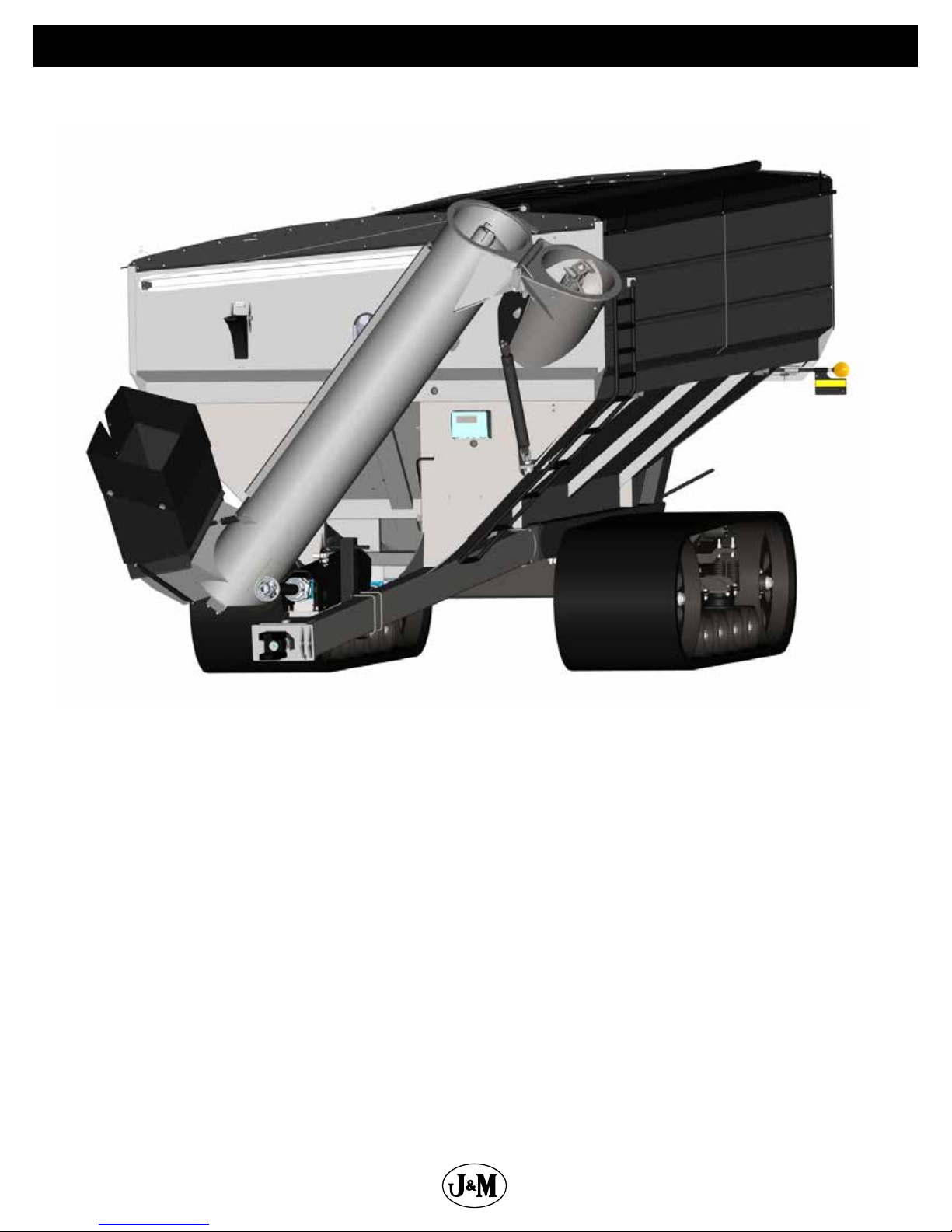
GRAIN CART
32 Series
OPERATOR’S MANUAL
MODEL
284 Railroad Street - P.O. Box 547 | Fort Recovery, OH 45846 | Ph: (419) 375-2376 | Fax: (419) 375-2708
Rev. 4.12.2019
J&M Manufacturing Co, Inc
www.jm-inc.com
Page 2
Stance
Opposite Auger
Side
Front
Rear
Auger Side
2
Page 3

Dealer Pre-Delivery Instructions Grain Cart
WHEEL NUTS
Check ALL wheel nuts for correct torque setting. (3/4”-400 Ft-Lbs, 22mm-640 Ft-Lbs)
Tighten as needed. Re-Check wheel nut torque settings during initial break in period
(during 1st, 2nd, 3rd loads, etc.), then periodically afterwards (every 10 hours of use for rst
40 hours). Keep checking wheel nut settings until wheel nuts do not loosen. If wheel nuts
loosen and damage the surface of the wheel center, it will be impossible to keep them
tight. Failure to keep the wheel nuts tight could cause considerable damage to the grain
cart and surrounding area. To ensure that wheel nuts do not loosen, it may be helpful to
mark the location of one side of the nut and wheel rim with paint. This will help when
observing if any rotation of the nut occurs. It is the Dealer’s responsibility to have wheel
nuts torqued to specication before delivery. Damage caused by failure to keep the wheel
nuts tight is not warrantable.
HITCH
Determine the hitch style of cart to be compatible with tractor. Tractor with hammer strap
(clevis type) should be used with grain carts equipped with a single prong (spade) hitch.
Tractors equipped with a single prong hitch (no hammer strap) should be used with grain
carts equipped with a double prong (clevis) hitch.
Be sure the tractor pin is at least 1/4” smaller in diameter than the pin hole in the grain cart
hitch to ensure enough free movement when traversing through uneven terrain.
POWER TAKE-OFF
Check for adequate clearance between telescoping PTO and tractor hitch. Suggested
clearance is 7 inches.
Check telescoping PTO for adequate extension. With the tractor hitched to the cart on at
level ground, the PTO should have approximately 10 inches extended from the collapsed
(shortest) length.
HYDRAULIC CYLINDERS AND HOSES
Run all functions of the hydraulic cylinders and inspect ttings and seals for leakage. (use
cardboard or wood to check for hydraulic leaks)
UPPER AND LOWER AUGERS
Raise the auger to the unload position. Run the auger from the PTO or optional hydraulic
motor. If the top auger is misaligned with the bottom auger, you will hear a ‘bang’ as
the upper auger realigns itself with the lower auger. This is normal as the top auger has
dropped to engage the lower auger. Be sure that the top auger engages the lower auger.
Check bearing at top of auger. Be sure to have approximately 1/8” to 3/16” gap under/
between top auger bearing. If there is no gap under the bearing, or the gap is greater than
1/8” to 3/16”, the bearing needs adjusted.
(Continued on Next Page)
3
Page 4

Dealer Pre-Delivery Instructions Grain Cart
GEARBOX
Check the gearbox oil level. For the process of checking the oil in your gearboxes, refer to
“Lubrication Service Schedule” in this manual. Add SAE 80W-90 lubricant as necessary.
LIGHTING & SAFETY FEATURES
Check the tractor lighting system for functions. Plug the grain cart wire harness into the
tractor receptacle and check the cart lighting for correct functions.
Check that the safety chains are properly installed. Use bolt-torque chart listed in
operator’s manual for correct torque value.
TIRES
All tires need to be inated to the specied air pressure given in the “Tire Pressure” section
on the “Initial Operation & Maintenance” page of this manual.
4
Page 5

Table Of Contents
6 .............................................................................................To The Dealer
7 ...................................................................................... General Information
8 .............................................................................................Specications
8 ...............................................................................................Dimensions
9 .........................................................................................Bolt Torque Chart
10 ...................................................................................................Decals
12 ............................................................................................. Safety Rules
13 ....................................................................... Initial Operation and Maintenance
13 ....................................................................................Routine Maintenance
14 ...................................................................................Operating Instructions
15 .........................................................................................Troubleshooting
16 .............................................................................Lubrication Service Schedule
18 .................................................................Adjusting the Lower and Upper Flighting
19 ............................................Removing Dirt From The Restrictors On The Hydraulic Cylinder
19 ....................................................................Rear Disconnect Annual Maintenance
20 ..................................................................................................Storage
Repair Parts List and Diagrams
20 .................................................................................... Wheel Rims and Tires
21 ................................................Hub & Spindle Assembly 250-10 (Single Wheel Grain Carts)
22 .............................................Hub and Spindle Assembly 550-20 (Single Wheel Grain Carts)
23 ...........................................Hub & Spindle Assembly W-881 (Walking Tandem Dual Wheels)
24 .....................................................................Power Take-O (PTO) Shaft Assembly
25 ..........................................................................................Hitch Assembly
26 ......................................................................................90 Degree Gear Box
27 ................................................................................... 3 Directional Gear Box
28 .................................................................................................Driveline
30 ...................................................................................Drag Auger Disengage
31 .........................................................................................Clean Out Doors
32 ............................................................................................... Feed Gate
33 ...................................................................................Lower Auger Assembly
34 .................................................................................... Upper Auger Linkage
35 ...................................................................................Upper Auger Assembly
35 .......................................................................... Upper Auger Bearing Assembly
36 ......................................................................................... Spout Assembly
38 ..............................................................................Hydraulic Hoses & Cylinders
40 ........................................................................... Auto-Gate Shut-O Hydraulics
42 ............................................................................Auto-Gate Shut-O Assembly
42 .................................................................... Auto-Gate Shut-O Wiring Schematic
43 ........................................................................................Lights and Wiring
44 .........................................................5-Point Scale System for Single Wheel Grain Carts
45 ...........................................................................5-Point Scale System for Tracks
46 ....................................................5-Point Scale System for Walking Tandem Dual Wheels
47 ...................................................................Walking Tandem Dual Wheel Assembly
48 ......................................................................... Gate Indicator Display Assembly
49 .....................................................................................Auger Rest Assembly
50 ........................................................................................ Ladder Assembly
50 ..................................................................................... Inspection Windows
51 ..................................................................................Spring Return Assembly
52 .......................................................................................Roll Tarp Assembly
5
Page 6

To The Dealer
Read manual instructions and safety rules. Make sure all items on the Dealer’s Pre-Delivery and Delivery Check Lists are completed
before releasing equipment to the owner.
The dealer must complete the Warranty Registration found on the Dealer Portal website located at dealer.jm-inc.com. and return
it to J. & M. Mfg. Co., Inc. at the address indicated on the form. Warranty claims will be denied if the Warranty Registration has not
been submitted.
EXPRESS WARRANTY:
J. & M. Mfg. Co. Inc. warrants against defects in construction or materials for a period of ONE year. We reserve the right to inspect
and decide whether material or construction was faulty or whether abuse or accident voids our guarantee.
Warranty service must be performed by a dealer or service center authorized by J. & M. Mfg. Co., Inc. to sell and/or service the type
of product involved, which will use only new or remanufactured parts or components furnished by J. & M. Mfg. Co., Inc. Warranty
service will be performed without charge to the purchaser for parts or labor based on the Warranty Labor Times schedule. Under no
circumstance will allowable labor times extend beyond the maximum hours indicated in the Warranty Labor Times schedule for each
warranty procedure. The purchaser will be responsible, however, for any service call and/or transportation of the product to and
from the dealer or service center’s place of business, for any premium charged for overtime labor requested by the purchaser, and
for any service and/or maintenance not directly related to any defect covered under the warranty. Costs associated with equipment
rental, product down time, or product disposal are not warrantable and will not be accepted under any circumstance.
Each warranty term begins on the date of product delivery to the purchaser. Under no circumstance will warranty be approved
unless (i) the product warranty registration card has been properly completed and submitted to the equipment manufacturer, and
(ii) a warranty authorization number has been issued by the equipment manufacturer. This Warranty is eective only if the warranty
registration card is returned within 30 days of purchase.
This warranty does not cover a component which fails, malfunctions or is damaged as a result of (i) improper modication or
repair, (ii) accident, abuse or improper use, (iii) improper or insucient maintenance, or (iv) normal wear or tear. This warranty
does not cover products that are previously owned and extends solely to the original purchaser of the product. Should the original
purchaser sell or otherwise transfer this product to a third party, this implied, with respect to tires or other parts or accessories not
manufactured by J. & M. Mfg. Co., Inc. Warranties for these items, if any, are provided separately by their respective manufacturers.
THIS WARRANTY IS EXPRESSLY IN LIEU OF ALL OTHER WARRANTIES OR CONDITIONS, EXPRESS, IMPLIED OR STATUTORY, INCLUDING
ANY IMPLIED WARRANTY OF MERCHANTABILITY OR FITNESS FOR PARTICULAR PURPOSE.
In no event shall J. & M. Mfg. Co., Inc. be liable for special, direct, incidental or consequential damages of any kind. The exclusive
remedy under this Warranty shall be repair or replacement of the defective component at J. & M. Mfg. Co., Inc’s. option. This is the
entire agreement between J. & M. Mfg. Co., Inc. and the Owner about warranty and no J. & M. Mfg. Co., Inc. employee or dealer is
authorized to make any additional warranty on behalf of J. & M. Mfg. Co., Inc.
The manufacturer reserves the right to make product design and material changes at any time without notice. They shall not incur
any obligation or liability to incorporate such changes and improvements in products previously sold to any customer, nor shall
they be obligated or liable for the replacement of previously sold products with products or parts incorporating such changes.
SERVICE:
The equipment you have purchased has been carefully manufactured to provide dependable and satisfactory use. Like all
mechanical products, it will require cleaning and maintenance. Lubricate the unit as specied. Observe all safety information in
this manual and safety signs on the equipment.
For service, your authorized J. & M. dealer has trained mechanics, genuine J. & M. service parts, and the necessary tools and
equipment to handle all your needs.
Use only genuine J. & M. service parts. Substitute parts may void warranty and may not meet standards required for safety and
satisfactory operation. Record the model number and serial number of your equipment in the spaces provided:
Model No:1132 Serial No: ________________________ Date of Purchase: ___________________
Purchased From: ________________________________________________________________________________
Provide this information to your dealer to obtain correct repair parts.
6
Page 7

General Information
TO THE OWNER:
The purpose of this manual is to assist you in operating and maintaining your grain cart in a safe manner. Read it carefully. It
furnishes information and instructions that will help you achieve years of dependable performance and help maintain safe operating
conditions. If this machine is used by an employee or is loaned or rented, make certain that the operator(s), prior to operating:
1. Is instructed in safe and proper use.
2. Reviews and understands the manual(s) pertaining to this machine.
Throughout this manual, the term IMPORTANT is used to indicate that failure to observe can cause damage to equipment. The
terms CAUTION, WARNING and DANGER are used in conjunction with the Safety-Alert Symbol (a triangle with an exclamation mark)
to indicate the degree of hazard for items of personal safety. When you see this symbol, carefully read the message that follows and
be alert to the possibility of personal injury or death.
This Safety-Alert symbol indicates a hazard and means
ATTENTION! BECOME ALERT! YOUR SAFETY IS INVOLVED!
DANGER
WARNING
CAUTION
IMPORTANT
NOTE
Indicates an imminently hazardous situation that, if not avoided, will result in death or serious injury.
Indicates a potentially hazardous situation that, if not avoided, could result in death or serious injury,
and includes hazards that are exposed when guards are removed.
Indicates a potentially hazardous situation that, if not avoided, may result in minor or moderate injury.
Indicates that failure to observe can cause damage to equipment.
Indicates helpful information
.
7
Page 8
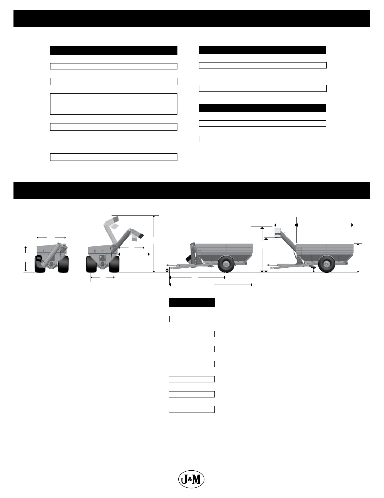
SPECIFICATIONS
Specications
Single Wheel Option
Capacity
Auger, One Vertical
Auger, One Horizontal
Unload Rate
(2)
Wheels
Tires (2)
Hubs (2)
(2)
Spindles
Tongue Weight
Empty
Loaded
Total Weight
(approx.)
MODEL 1132
1,150 Bushels
22”
20”
Up to 740+ Bushels/Minute
30x32, 32x36 or 44x32
900/60R32,
1050/50R32, or
1250/50R32
10 Bolt or 20 Bolt
6” Diameter
2,600 lbs.
3,800 lbs.
18,650 lbs.*
Dimensions
Walking Tandem Dual Wheels Option
Capacity
(4)
Wheels
Tires (4)
Spindles (4)
Total Weight (approx.)
Tracks Option
Capacity
Tracks (2)
Total Weight (approx.)
Compaction Rate
1,125 Bushels
16x42, 18x38, 18x42
480/80R42, 520/85R38
or 520/85R42
4 1/2” Diameter
21,700 lbs.
1,175 Bushels
36”x116” or 36”x146”
25,400 lbs.
16.6 lbs/sq inch (36”x116”)
11.2 lbs/sq inch (36”x146”)
KN
B
C
D
A
Eective Side Reach
(throw)
E
F
G
O
J
L
M
H
I
MODEL 1132
A
B
C
D
E
F
G
H
I
J
K
L
M
N
O
* Measured with 1250/50R32 tires, scales, roll tarp
installed and a 20” hitch height
*
10’-4”
11’-9”
11’-0”
13’-8”
10’-0”
22’-2”
1’-6”
22’-4”
33’-0”
13’-6”
22’-10”
11’-6”
1’-11”
8’-6”
17’-8”
8
Page 9
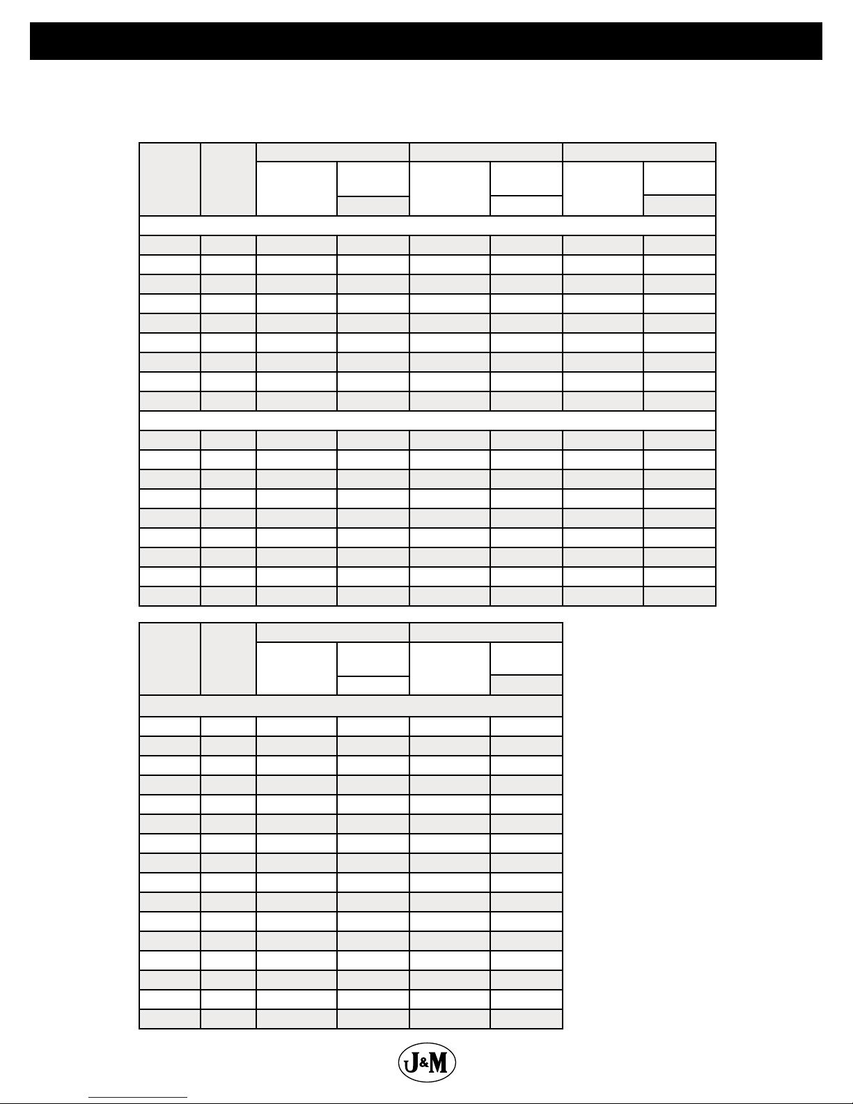
Bolt Torque Chart
Always tighten hardware to these values unless a dierent torque or tightening procedure is listed for specic application.
Fasteners must always be replaced with the same grade as specied in the manual parts list.
Always use the proper tool for tightening hardware. SAE for SAE hardware and Metric for Metric hardware.
Make sure fastener threads are clean and you start thread engagement properly.
Nominal
Dia. (Inch)
1/4 20 1313 59 in-lbs. 2029 90 in-lbs. 2864 129 in-lbs.
5/16 18 2163 122 3342 188 4719 265
3/8 16 3196 18 -lbs. 4940 28 -lbs. 6974 39 -lbs.
7/16 14 4385 29 6777 44 9568 63
1/2 13 5853 44 9046 68 12771 96
5/8 11 9323 87 14408 135 20340 191
3/4 10 13797 155 21322 240 30101 339
7/8 9 11428 150 29436 386 41556 545
1/4 28 1500 68 in-lbs. 2319 104 in-lbs. 3274 147 in-lbs.
5/16 24 1395 135 3702 208 5226 294
3/8 24 3623 20 -lbs. 5599 31 -lbs. 7905 44 -lbs.
7/16 20 4897 32 7568 50 10684 70
1/2 20 6598 49 10197 76 14396 108
5/8 18 10558 99 16317 153 23036 216
3/4 16 15385 173 23776 267 33566 378
7/8 14 12609 165 32479 426 45853 602
reads
Per
Inch
1 8 14992 225 38616 579 54517 818
1 14 16827 252 43343 650 61190 918
SAE J429 Grade 2 SAE J429 Grade 5 SAE J429 Grade 8
Clamp Load
(Lbs.)
Tightening
Torque
K = 0.18
Unied Coarse read Series
Clamp Load
(Lbs.)
Fine read Series
Tightening
Torque
K = 0.18
Clamp Load
(Lbs.)
Tightening
Torque
K = 0.18
Nominal
Dia. (Inch)
10 1.5 5671 33.5 8115 47.9
12 1.75 8240 58.4 11792 83.5
14 2 11289 93.3 16154 133.5
16 2 15320 144.7 21924 207.1
18 2.5 18822 200.0 26934 286.2
20 2.5 23938 282.7 34256 404.5
22 2.5 29669 385.4 42457 551.5
24 3 34471 488.4 49329 699
27 3 44924 716.1 64288 1024.8
30 3.5 54819 970.9 78448 1389.5
33 3.5 67821 1321.4 97055 1890.9
36 4 79866 1697.5 114291 2429.2
Pitch Class 8.8 Class 10.9
Clamp Load
(Lbs.)
5 0.8 1387 4.1 1985 5.9
6 1 1968 7.0 2816 10.0
7 1 2822 11.7 4039 16.7
8 1.25 3580 16.9 5123 24.2
Tightening
Torque
K = 0.18
Metric Fasteners
Clamp Load
(Lbs.)
Tightening
Torque
K = 0.18
TIGHTENING WHEEL NUTS
Standard 3/4” wheel studs and nuts
should be tightened to torque 400
Ft.-Lbs and standard 22mm studs
should be tightened to torque 640
Ft.-Lbs. during initial operation of
the grain cart and then checked for
proper torque after every 10 hours
of use. Failure to do so may damage
wheel nut seats. Once seats are
damaged, it will become impossible
to keep nuts tight.
9
Page 10
1
9
8
7
6
5
4
3
2
10
14
13
15
17
16
19
18
20
23
16
24
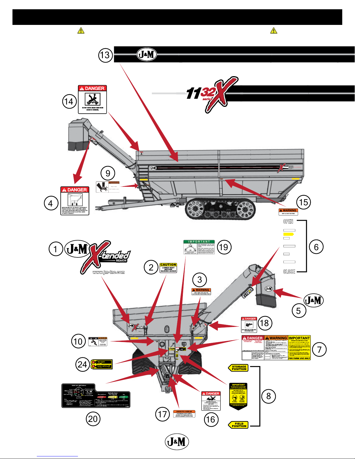
Decals
ATTENTION! BECOME ALERT! YOUR SAFETY IS INVOLVED!
Replace Immediately If Damaged or Missing
10
Page 11
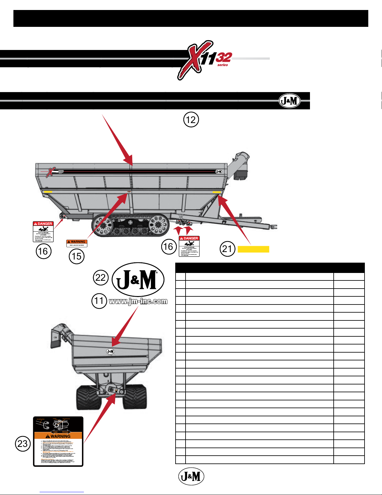
Decals
12
11
22
23
16
21
16
15
Description Part No.
1 X-Tended Reach Logo w/ Oval and Website (Dual Auger) Decal JM0048321
2 Caution Lower Rest Decal JM0037662
3 Warning, Keep Hands Away Decal JM0018039
4 Danger, Electric Lines Decal JM0015099
5 J&M Oval Decal (Medium) 5-1/2”x8-1/2” JM0010179
6 Open and Close Decal for 32 Series Indicator JM0043138
7 Danger Warning Important Decal JM0037665
8 Field Position/Storage Position Decal JM0037661
9 Warning, Pinch Point Decal JM0014994
10 Warning, Falling Or Lowering Decal JM0014992
11 www.jm-inc.com Decal JM0019239
12 1132 Opposite Auger Side Stripe Kit JM0044291
13 1132 Auger Side Stripe Kit JM0044290
14 Danger, Do Not Enter Grain Tank Decal JM0018033
15 Warning, Keep Lug Nuts Tightened Decal 1-5/8” x 4” JM0010150
16 Danger, Rotating Driveline Decal JM0018036
17 Check PTO Overlap Decal JM0025435
18 Danger, Keep Hands and Clothing Away Decal JM0018035
19 Important, 3x Wide Turns Tracks Decal JM0021247
20 Light Harness/Hydraulic Hoses Decal JM0046492
21 Amber Reective Decal (2” x 9”) (RD-1A) JM0009946
22 J&M Oval Decal (Large) 9-1/2” x 15” JM0015151
23 Drag Auger Disengage Instructions Decal JM0048320
24 Lock and Load Indicator Lights Decal JM0044289
11
Page 12

Safety Rules
ATTENTION! BECOME ALERT! YOUR SAFETY IS INVOLVED!
Safety is a primary concern in the design and manufacture of our products. Unfortunately, our eorts to provide safe equipment
can be erased by an operator’s single careless act. In addition, hazard control and accident prevention are dependent upon the
awareness, concern, judgment, and proper training of personnel involved in the operation, transport, maintenance and storage of
equipment.
Make certain that the operator(s), prior to operating is instructed in safe and proper use and reviews and understands the manual(s)
pertaining to this machine. Also make certain that the operator(s) reviews and understands the operator’s manual of the tractor
prior to hooking up or operating the grain cart.
Read this manual before you operate this machine. If you do not understand any part of this manual, or need more information,
contact the manufacturer or your authorized dealer.
SAFETY
Understand that your safety and the safety of other persons is measured by how you service and operate this machine. Know the
positions and functions of all controls before you try to operate them. Make sure to check all controls in a safe area before starting
your work.
The safety information given in this manual does not replace safety codes, federal, state or local laws. Make certain your machine
has the proper equipment as designated by local laws and regulations.
A frequent cause of personal injury or death is from persons falling o equipment and being run over. Do not permit persons to
ride on this machine.
Travel speeds should be such that complete control and machine stability is maintained at all times. Where possible, avoid operating
near ditches, embankments and holes. Reduce speed when turning, crossing slopes and rough, slick or muddy surfaces.
Collision of high speed road trac and slow moving machines can cause personal injury or death. On roads, use asher lights
according to local laws. Keep slow-moving-vehicle emblem visible. Pull over to let faster trac pass.
Hydraulic oil leaking under pressure can penetrate skin and cause infection or other injury. To prevent personal injury,
• Relieve all pressure, before disconnecting uid lines,
• Before applying pressure, make sure all connections are tight and components are in good condition,
• Never use your hand to check for suspected leaks under pressure. Use a piece of cardboard or wood for this purpose.
• If injured by leaking uid, see your doctor immediately.
When transporting the grain cart, always keep the auger in the stow position.
Use care when moving of operating the grain cart near electric lines as serious injury or death can result from contact.
Never adjust, service, clean, or lubricate the grain cart until all power is shut o. Keep all safety shields in place. Keep hands, feet,
hair and clothing away from moving parts while the grain cart is in operation.
The service ladder is for service work only. If you must climb into the grain tank, be certain that all power is shut o and then use
extreme caution when climbing into the grain cart.
Make sure that everyone is clear of equipment before applying power or moving the machine.
Make sure that the grain cart is fastened securely to the tractor by using a high strength hitch pin, clip and safety chains. Make sure
that the grain cart hitch properly matches the hitch type of the tractor. Use a single prong (spade) grain cart hitch with a double
prong (clevis) tractor hitch. Use a double prong (clevis) grain cart hitch with a single prong (spade) tractor hitch.
Before lling the grain cart, make certain that no one is inside the grain tank. Never allow children or anyone in, near, or on the
grain cart during transport or during loading and unloading of grain. Be aware that moving grain is dangerous and can cause
entrapment, resulting in severe injury or death by suocation.
Never operate the auger system with anyone inside the grain tank. Hands, feet, hair and clothing can t through the openings in
and around the grate. Contact with the auger can cause severe injury or death. Make certain that all power is shut o before service
work is performed.
Before unhooking the grain cart from the tractor, be sure the jack stand is properly mounted and in place and the wheels are
properly blocked to prevent the cart from moving.
12
Page 13
Initial Operation and Maintenance
WARNING
BE CERTAIN THAT ALL POWER IS SHUT OFF BEFORE SERVICING THE GRAIN CART.
Before the grain cart is put into service:
Have the safety instructions been read and clearly understood by the operator(s) of this machine?
Have the gearboxes been properly lled with SAE 80W-90 gearbox lubricant?
Have all nuts, bolts, bearings and braces been properly fastened?
Has the PTO been checked for proper overlap?
CHECK PTO OVERLAP LENGTH. Overlap length may vary depending on the tractor model and hitch setting. Try to obtain the
greatest possible overlap without bottoming out in the extreme operating conditions. Too much overlap may cause the PTO to
bottom out and damage the driveline. Not enough overlap may cause the PTO front and back halves to separate. From the fully
compressed (shortest) length the PTO should be telescoped (extended) between 10” and 22”. Dierent PTO lengths may need
to be purchased to accommodate your terrain. A 4” shorter or a 10” longer PTO can be ordered through your dealer from J&M
Manufacturing.
GREASE BEARINGS: Are all bearings on the drive line properly greased? Are all set screws and bolts in the bearings and U-joints
tight? Has the power-take-o shaft been properly greased at all points including the cross bearings? Have the universal joints at
the gearbox been greased? Have all grease points at the auger hinge area, including the hanger bushing assembly been greased?
Has the horizontal auger hanger been greased?
TIRE PRESSURE: Are the tires properly inated? The following is to be used as a general guide for tire ination for cyclic use.
Figures can vary depending on specic brand of tire used. It is important that tires are inspected before and after the unit is
loaded. The tire should stand up with no side wall buckling or distress as the tire rolls. Do Not Exceed The Tire Pressure
Indicated Below:
Tires psi
1050/50R32 Lug Tires (Alliance) (185 LI) (for 32x36-10 Hole Wheels) 56
480/80R42 Lug Tires (Firestone) (154 LI) (for16x42-10 Hole Wheels) 35
480/80R42 Lug Tires (Alliance) (169 LI) (for16x42-10 Hole Wheels) 64
IF520/85R42 Lug Tires (Firestone) (169 LI) (for 18x42-10 Hole Wheels) 44
520/85R42 Lug Tires (Alliance) (169 LI) (for 18x42-10 Hole Wheels) 50
IF900/60R32 Lug Tires (Alliance) (192D LI) (for 30x32-10 Hole Wheels) 66
IF1250/50R32 Lug Tires (Firestone) (188 LI) (for 44x32-10 Hole and 44x32-20 Hole Wheels) 23
IF1250/50R32 Lug Tires (Firestone) (201B LI) (for 44x32-10 Hole and 44x32-20 Hole Wheels) 46
IF1250/50R32 Lug Tires (Alliance) (201A8 LI) (for 44x32-10 Hole and 44x32-20 Hole Wheels) 46
Routine Maintenance
WARNING:BE CERTAIN ALL POWER IS SHUT OFF WHEN SERVICING THE GRAIN CART
• Repack the bearings in the hub assembly once a year or as needed. Use a good quality LS EP2 Severe Duty, High Shock Load,
Lithium based Grease. Also check the seal for wear and replace if necessary.
• Check the grain cart periodically for cracks in welds and for other structural damage. Have cracked welds xed immediately.
Failure to do so could result in extensive damage to the grain cart and greatly reduce the life of the cart.
• Exercise horizontal and vertical clean out doors. Lubricate hinge points if necessary.
• Check all hydraulic hoses for wear and replace as necessary.
• Make sure all tires are properly inated. Refer to the chart above for recommended instructions on tire pressure. It is important
that tires are inspected before and after unit loaded.
• Make sure that all guards and shields are in place before operating the grain cart.
13
Page 14
Operating Instructions
VERY IMPORTANT: Under no circumstance is it recommended to tow a loaded grain cart in excess of 8 mph.
WHEEL NUTS: Are the wheel nuts properly fastened? Torque to 640 Ft.-Lbs. for standard 22mm wheel studs and nuts. Torque to
400 Ft.-Lbs. for 3/4” wheel studs and nuts. Wheel studs and nuts should be checked after each load during initial operation of
the cart and then after every 10 hours of use. Failure to do so may damage wheel studs and nuts. To ensure that wheel nuts do
not loosen, it may be helpful to mark the location of one side of the nut and wheel rim with paint. This will help when observing if any
rotation of the nut occurs. Once the seats are damaged, it will become impossible to keep the lug nuts tight.
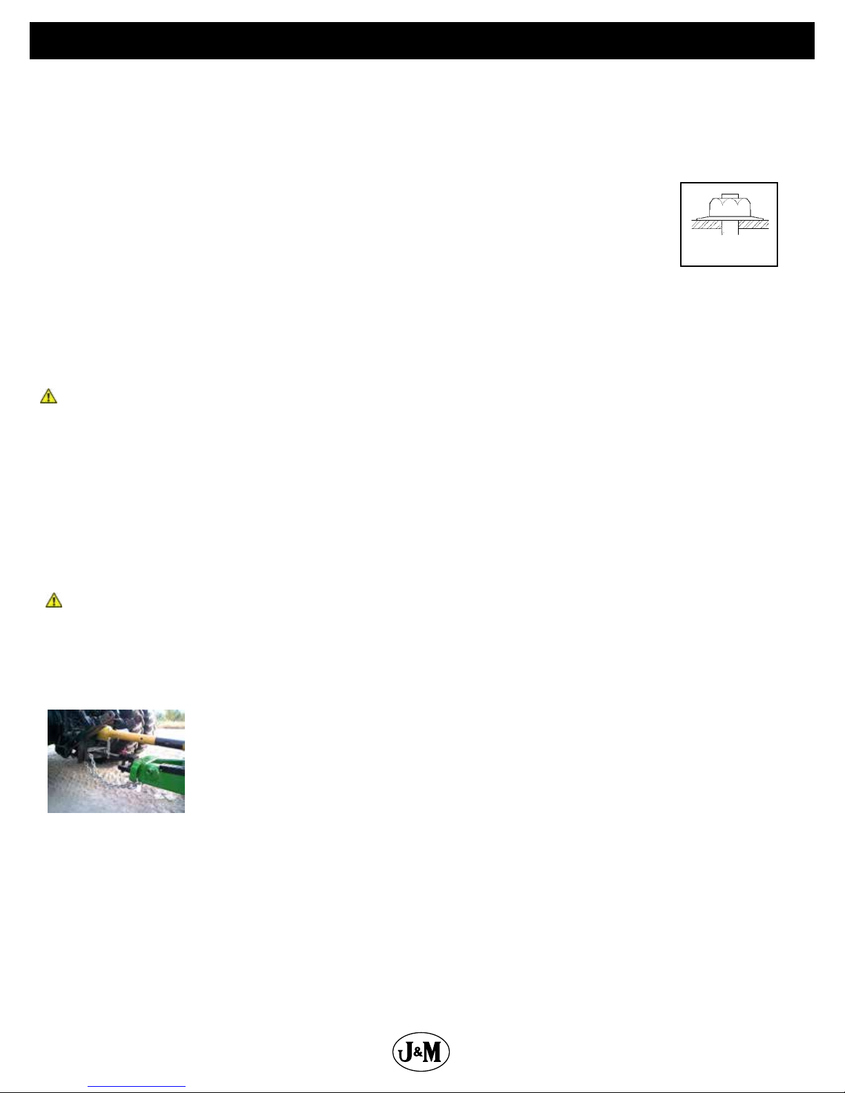
The drawing shows the proper way to mount the wheels using Budd-type nuts. The wheels supplied with
your grain cart have straight holes and the Budd nuts will be mounted according to Figure 1. Wheels that
are improperly installed on the grain cart, resulting in product failure, will nullify warranty and shift the
burden of liability to the owner/operator. We recommend you inspect your wheel nuts to make sure they
are properly installed. Also, check the wheel nuts on a regular basis to ensure they are tight.
LIGHTING AND SAFETY DECALS: Are the rear, amber extremity lights properly positioned? Extend the lights within 16” (40,6cm) of the
left and right extremities of the grain cart. Is an SMV Emblem attached to the rear of the grain cart?
Are the lights working properly? Are all lights and reective decals clean, visible and properly placed?
BE CERTAIN THAT ALL POWER IS SHUT OFF WHEN HOOKING UP TO TRACTOR OR CONNECTING HYDRAULIC LINES TO TRACTOR.
PREPARING THE GRAIN CART FOR USE: Model 1132 grain carts require 250+HP 4WD Tractor.
IMPORTANT: Do NOT pull a loaded grain cart on highway. For incidental highway travel, observe the section below.
Tow Loads Safely
Stopping distance increases with speed and weight of towed loads, and on slopes. Towed loads with or without brakes that are too heavy
for the tractor or are towed too fast can cause loss of control. Consider the total weight of the equipment and its load.
Observe these recommended maximum road speeds, or local speed limits which may be lower.
Road Travel (grain cart empty): Do not travel more than 20 mph (32 km/hr) and do not tow loads more than 1.5 times the
pulling unit’s weight.
Ensure the load does not exceed the recommended weight ratio. Use additional caution when towing loads under adverse surface
conditions, when turning, and on inclines.
WARNING: For greater stability on uneven or steep terrain, position non-scale wheel spindles at the furthest out setting.
IMPORTANT:
1) Connect grain cart hitch to tractor drawbar using a good quality hitch pin. Attach the safety chain to the tractor and through one chain
loop provided on either side of the grain cart frame as shown. Make sure the grain cart hitch properly matches the hitch of the tractor.
Use a single prong (spade) grain cart hitch with a tractor double prong (clevis) hitch. Use a double prong (clevis) grain cart hitch with
a single prong (spade) tractor hitch.
Safety Chain User Instruction
a) Secure the safety chain by looping it around each side of the grain cart as shown and
connecting to the towing machine’s attaching bar.
b) Do Not allow any more slack than necessary for articulation.
c) Do Not use any intermediate support as the attaching point.
d) Store the safety chain by securing it around the main axle A-frame of the grain cart.
e) Replace the safety chain if one or more links or end ttings are broken, stretched or otherwise
damaged or deformed.
2) Attach the power-take-o shaft to the tractor. The PTO must have at least 10” of engagement. Check tractor drawbar for clearance and
length and adjust if necessary. Make sure the PTO does not bottom out when making sharp turns as it may bend the drive shaft.
3) Make sure the jack stand is removed from the lower support position before the cart is moved. Never use the jack to support a
loaded grain cart.
4) Be sure that no debris or foreign objects are in the grain cart.
5) Attach the hydraulic lines to the tractor. Two hydraulic lines (green band) operate the inside gate mechanism. Connect these lines
to one service outlet on the tractor. Two hydraulic lines (yellow band) operate the folding mechanism of the auger. Connect these lines
to a second service outlet on the tractor. The remaining two hydraulic lines (red band) operate the hydraulic ow control spout located
at the end of the upper auger. Connect these lines to a third service outlet on the tractor. Make sure the air is bled from the hydraulic
cylinders and hoses.
Figure 1
14
Page 15
Operating Instructions
6) Run the auger system EMPTY before loading grain into the tank for actual use. Make certain that the slip clutch is operating and that
the upper, lower, and horizontal augers are properly engaged.
7) Connect the lighting 7-prong connector end on the main wiring harness to the tractor electrical outlet. Make sure that all asher and
turn indicator lights are working properly before incidental highway travel.
CAUTION
• Do NOT operate the grain cart before reading and understanding the Operator’s Manual and ALL danger, warning and caution
signs.
• Be sure that a Slow-Moving-Vehicle emblem is attached to the rear of the grain cart.
• Never exceed 1,000 rpm on the PTO and driveline system.
• Never fold or extend the auger until the PTO has come to a complete stop.
• Never ll the grain cart unless the gate indicator is in the closed position.
• Never allow foreign object (shovels, etc.) to be placed inside the grain cart.
• Never engage the lugs and drive dogs on the augers when the system is moving at a high rate of speed.
• Never perform maintenance work or service the grain cart with the tractor running.
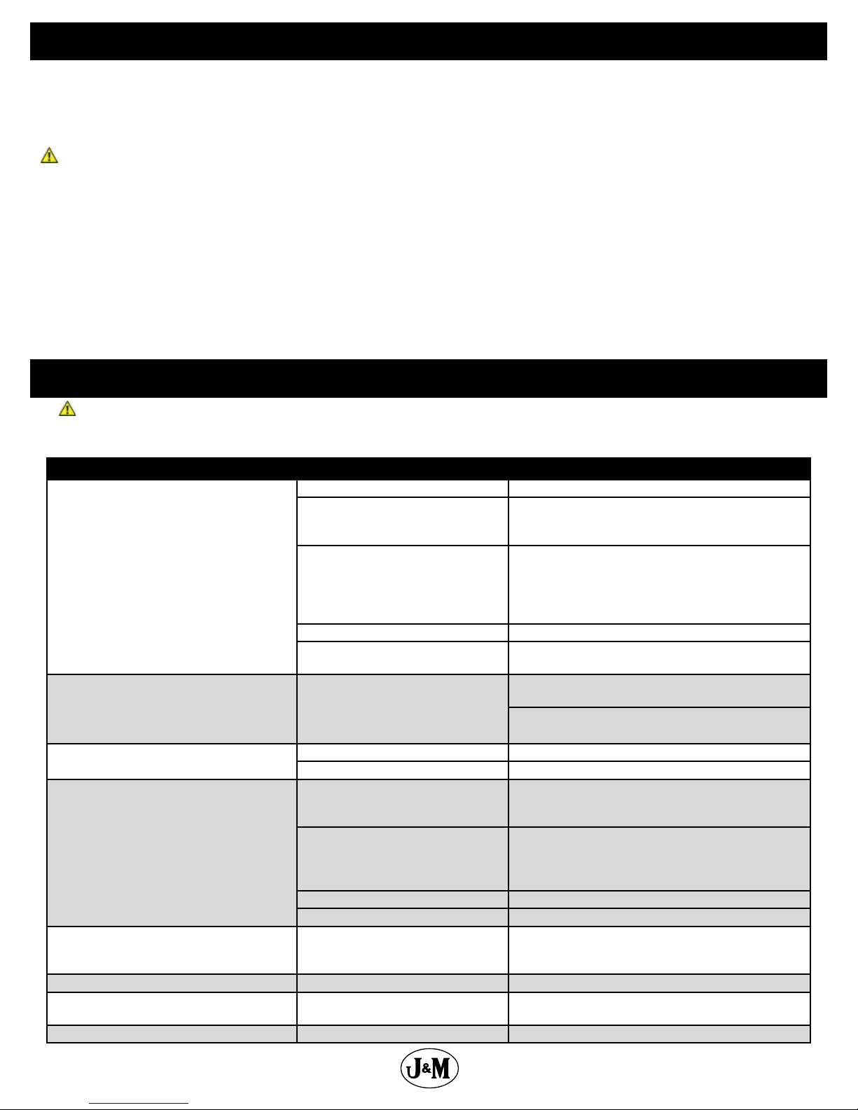
Troubleshooting
WARNING
MAKE SURE THAT ALL POWER IS SHUT OFF BEFORE SERVICING THE GRAIN CART. MAINTENANCE AND
REPAIR SERVICE WORK TO BE PERFORMED BY QUALIFIED SERVICEMEN ONLY.
Trouble Possible Cause Possible Remedy
Faulty check valve Replace check valve
Faulty lock and load solenoid Disconnect power to lock and load. If the auger is
able to move, the lock and load solenoid needs to be
replaced
Upper ighting and lower ighting are
Auger will not return to down position or
move from stow position
Hanger bushing assembly at the top of the
lower auger ighting is hot
Excessive vibration
Grain ow stoppage
Auger tube is breaking away from the grain
cart at the hinge area or the ram in the hydraulic folding cylinder is bent
Flip-up auger rest not ipping over center Cable has loosened With auger in eld position, tighten cable to the handle.
Feed gate indicator not moving Debris lodged in feed gate Make sure indicator slider moves freely and feed gate is
Clutch disconnecting Auto-clutch torque exceeded
locked together
Feed gate open Close the feed gate
Lock and Load not operating correctly Make sure the limit switch on the feed gate indicator
Top of the hanger bushing assembly is
rubbing against the drive dog
Auger ighting or shaft is bent Straighten or replace auger ighting.
Drive shaft is bent Replace or straighten drive shaft.
Bolt sheared in drive dog Replace bolt in drive dog. Engage upper and lower
Folding auger before complete stop Upper and lower ightings are disengaging before au-
PTO key sheared Replace key and tighten set screw.
Rear auger disconnect disengaged Engage rear auger disconnect
Upper auger is extended in the
upright position while traveling in the
eld
Bearing on top of upper auger ighting needs
adjusting. When the auger is in the engaged position,
there must be 1/8” (0,32cm) gap between bottom of top
bearing and top of upper tube housing (See “Adjusting
the Lower and Upper Flighting” on page 18)
assembly is functioning properly
Loosen the two bolts and re-adjust the position of the
hanger bushing assembly. Re-tighten bolts.
Remove the lower ighting assembly and place a shim
between the spline coupler and the gearbox.
ighting at a slow rate of speed. (Drive dogs and lugs
are being engaged too fast.)
ger comes to a complete stop. Replace bolt in the drive
dog. Never engage or disengage the upper and lower
ightings until the augers come to a complete stop.
Repair or place folding cylinder if necessary. Remember
to lower auger to the eld position after unloading.
clear of debris
Operate rear auger disconnect
15
Page 16
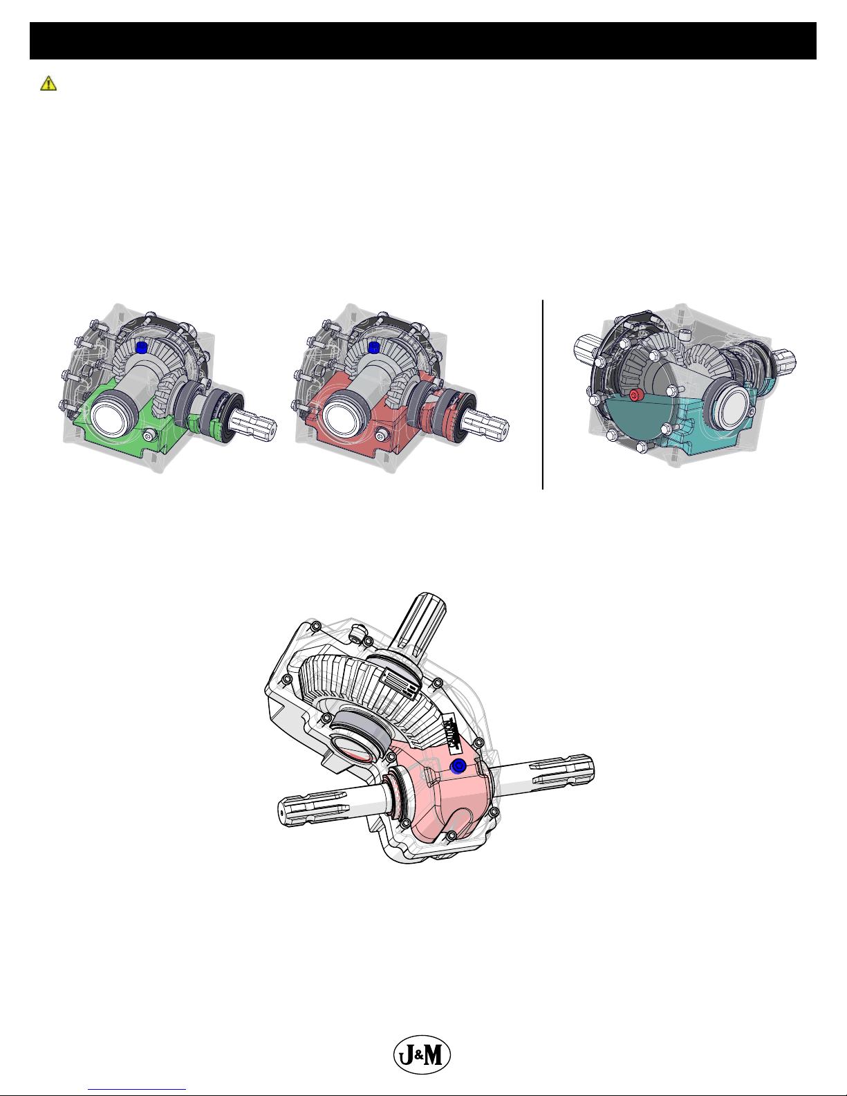
Lubrication Service Schedule
WARNING: BE CERTAIN THAT ALL POWER IS SHUT OFF BEFORE SERVICING THE GRAIN CART
90 DEGREE REAR GEARBOXES: Gearbox lubricant has been added to the gearboxes during nal assembly. Recheck the lubricant level
before initial operation of the grain cart, then periodically according to use. For the gearbox on the left while looking from the rear of the
cart, the uid level should be between the bottom and halfway point of the 2” output shaft that bisects the gearbox. The recommended
uid level range is pictured in Figure 1 and Figure 2 below. The minimum level is pictured in green and the maximum level is pictured in
red. An pressure relief plug plug is located in the center of the top of the gearbox mount plate. To check the uid level, remove the vented
inspection plug and view the uid level from above. When lled to the maximum level (shown in red), the gearbox should have 80 ounces
of
SAE 80W-90 lubricant. Change the oil annually before use.
For the gearbox on the right while looking from the rear of the cart, the uid level should rest at the inspection plug, pictured in red in Figure
3 below. When lled to the proper level, the gearbox should have 80 ounces of
SAE 80W-90 lubricant. Change the oil annually before use.
Figure 1 Figure 2 Figure 3
3-WAY FRONT GEARBOX: Gearbox lubricant has been added to the gearbox during nal assembly. Recheck the lubricant level before
initial operation of the grain cart, then periodically according to use. The uid level should rest at the inspection plug, pictured in blue in
Figure 4 below. When lled to the proper level, the gearbox should have 96 ounces of
use.
SAE 80W-90 lubricant. Change the oil annually before
Figure 4
REAR DISCONNECT GROOVED SPLINE COUPLER: Exercise the disconnect handle, adding a lubricant to the 2” output shaft on the rst
gearbox where the grooved spline coupler slides. Loctite Silver Grade Anti-Seize is recommended. Perform this maintenance annually.
16
Page 17

Lubrication Service Schedule
Roll Tarp U-Joint
IMPORTANT: Your grain cart has grease ttings at all critical points. The following grease ttings should be serviced before the grain
cart is put into operation:
PTO & DRIVELINE: The grease ttings on the PTO should be serviced after every 8 hours of use. Service the grease ttings on each of
the drive bearings and also the universal joints after every 8 hours of use.
AUGER ASSEMBLY: One grease tting is located on the pivot pin of the folding auger. This tting should be serviced after every 8 hours
of use. Service the grease tting on the hanger bushing assembly (top end of the lower auger assembly) as well as the horizontal auger
hangers after every 8 hours of use or as needed.
SPRING LOADED UPPER AUGER BEARING: Service the grease tting on the upper auger bearing (located at the top end of the upper
auger assembly) after every 8 hours of use. Lubricate the springs and retaining bolts on the bearing before prolonged storage of the
grain cart.
ROLL TARP U-JOINT: Service the grease tting on the U-Joint of the roll tarp crank handle once annually.
Grease Fittings
Pivot Pin Once Annually
Roll Tarp U-Joint Once Annually
Upper Auger Flighting Every 8 hours of use
Driveline Every 8 hours of use
Horizontal and Vertical Flighting Hangers Every 8 hours of use
Pivot
Upper Auger Flighting
Flighting Hangers
Drive Line x2
Drive Line x3
17
Page 18

Adjusting the Lower and Upper Flighting
WARNING
MAKE SURE THAT ALL POWER IS SHUT OFF BEFORE ADJUSTING THE FLIGHTING ASSEMBLY.
LOWER FLIGHTING - If the drive-dog and hanger assembly are becoming excessively hot during unloading, the lower ighting and/or
hanger may need adjusting. The hanger bushing assembly has elongated holes where it attaches to the outer tube assembly. Loosen the
two 1/2” bolts on the hanger bushing assembly. Adjust the hanger either up or down and vertically center it between the ighting and
drive dog. Re-tighten the bolts. Make certain that the ighting center and drive-dogs do not rub the hanger bushing assembly, causing
them to become hot.
If the hanger can no longer be adjusted by moving it up or down on the elongated holes, both the hanger bushing assembly and the
lower ighting will have to be removed. After removing them from the tube assembly, place a shim [between 1/8” (0,32cm) to 3/16”
(0,48cm) thick] where the gearbox and the spline coupler (welded to the lower ighting). Replace the lower ighting and reattach the
hanger to the tube assembly. Readjust the hanger assembly. NOTE: The bottom of the lower ighting is not attached to the gearbox
with any bolts or set screws but may be ‘frozen’ fast. Be careful when removing the lower ighting from the gearbox. For easier removal
of the lower ighting, keep the gearbox at the bottom intact, remove the two 1/2” bolts from the hanger bushing assembly and pull the
lower ighting o of the gearbox.
After adjusting the lower ighting, move the upper auger to the unload position and check the upper ighting for readjustment.
UPPER FLIGHTING - If the upper and lower augers to do not properly separate during the unfolding sequence, the upper ighting
may need adjusting. Before making adjustment to the upper ighting, check to see if the lugs and drive dogs on the auger assemblies
are locking together. If they are not locked together, check to see if a faulty check valve on the hydraulic cylinder used to raise and lower
the upper auger assembly may be causing the problem.
Fold the upper tube assembly into the upright position. Position the upper ighting in the engaged position with the lower ighting.
Locate the four-hole ange bearing on the top of the upper auger tube housing. With the upper ighting in the engaged position, check
the spacing between the upper bearing and the upper tube housing. There must be an 1/8” (0,32cm) space between the base of the
four-hole ange bearing and the upper tube housing. If there is NOT a space between the bearing and the upper tube housing, or if there
is more than 1/8” (0,32cm) space, the upper ighting will need to be adjusted. To adjust the upper ighting, loosen the 1 1/4” hex nuts
both above and below the four-hole ange bearing. Move the 1-1/4” hex nuts up or down the threaded shaft on the top of the auger
ighting shaft until the bearing moves to approximately 1/8” (0,32cm) above the base of the upper tube housing. When the four-hole
ange bearing is properly located, tighten both 1-1/4” hex nuts together to secure the bearing position.
If the upper and lower ighting still does not separate properly during the folding sequence, a small bevel may need to be removed from
the inside of the lugs where they engage the drive dogs on the auger assemblies. Grind approximately 1/8” (0,32cm) from the corner of
the lugs where they touch against the drive dogs.
18
Adjusting Upper Auger
2. Tighten the 1-1/4”
hex nut until there is
a 1/8” to 3/16” gap
between the 4 hole
ange bearing and
the headpan.
1/8”-3/16”
1. Untighten the
1-1/4” hex nut at
least 1/4”.
3.
hex nut back up.
Tighten the 1-1/4”
Page 19

Rear Disconnect Annual Maintenance
Before using the cart for the season:
1. Exercise the disconnect handle, adding a lubricant to the 2” output shaft on the rst gearbox where the grooved spline coupler slides.
Loctite Silver Grade Anti-Seize is recommended.
2. Check the face of the disconnect paddle for excessive wear (1/32” or more). In the event of excessive wear (1/32” or more), contact
the J&M Service Department.
Disengage Paddle, and Back Plate Settings
The back plate has a tab welded on the inside with a nut. A bolt and jam nut are screwed into it. The proper bolt setting maintains the
gap shown in the bottom right picture. The paddle is shown in purple here, and when the drivedogs are engaged there should be a
1/16” gap between the paddle and the drivedog. Having the gap will ensure that there is no unneccessary wear on parts.
Bolt and Jam Nut
Paddle
1/16”
1-3/4” Drive
Coupler
Engaged
2” Drive
Coupler
Removing Dirt From The Restrictors On The Hydraulic Cylinder
WARNING
MAKE SURE THAT ALL POWER IS SHUT OFF AND THE UPPER AUGER TUBE IS IN THE DOWN POSITION BEFORE REMOVING THE
RESTRICTORS
Remove restrictors from the 90 degree street elbow on the tip spout hydraulic cylinder. Remove dirt from the tting to allow hydraulic oil to
ow through the restrictor. Reattach the restrictor to the street elbow. Use Teon sealant tape or equivalent on the threads of the restrictor
before re-attaching.
If the restrictor continues to plug with dirt, replace the restrictor or lter the hydraulic oil in your system.
19
Page 20

Storage
IMPORTANT: When the grain cart is not going to be used for a period of time, store the cart in a dry, protected place. Leaving your grain
cart outside, open to the weather will shorten its life.
Procedure for Storage Preparation
1. Cover electronic monitor (if equipped) with plastic before washing the grain cart. Wash or clean and completely lubricate the grain
cart. See “Lubrication Service Schedule” on page 16.
2. Remove all grain from inside the grain tank, auger tube assemblies, and at the clean-out door.
3. Check the gearbox oil and replace with new SAE 80W-90 gearbox lubricant or equivalent if necessary.
4. Touch up areas where paint may have worn away. Use a good quality primer paint, especially before re-applying graphite paint to
the interior slopes of the grain tank.
5. Retract all hydraulic cylinders to prevent the piston rods from rusting.
6. Clean the tires before storage. Inate the tires at regular intervals.
7. Open the clean-out doors at the base of the grain tank.
Removing from Storage
1. Check the gearboxes to make sure they have the appropriate amount of oil.
2. Inate the tires to the correct operating pressure.
3. Close the clean out doors at the base of the grain tank.
4. Make sure all safety shields are in the proper position.
Repair Parts List and Diagrams
When performing maintenance work, wear sturdy, rough-soled work shoes and protective equipment for eyes, hair, hands, hearing
and head. Follow the Operator’s Manual instructions to ensure safe and proper maintenance and repair.
Your local, authorized dealer can supply genuine replacement parts. Substitute parts may not meet original equipment specications
and may be dangerous.
WARNING
MAKE SURE ALL POWER IS SHUT OFF BEFORE PERFORMING ANY MAINTENANCE OR REPAIR WORK.
Wheel Rims and Tires
Wheel Rims for Single Wheel Grain Carts
30x32-10 Hole Wheel Rims
32x36-10 Hole Wheel Rims (1 Piece)
44x32-10 Hole Wheel Rims
44x32-20 Hole Wheel Rims
Tires for Single Wheel Carts
IF900/60R32 Lug Tires (Alliance) (192D LI) (for 30x32-10 Hole Wheels)
1050/50R32 Lug Tires (Alliance) (185 LI) (for 32x36-10 Hole Wheels)
IF1250/50R32 Lug Tires (Firestone) (188 LI) (for 44x32-10 Hole and 44x32-20 Hole Wheels)
IF1250/50R32 Lug Tires (Firestone) (201B LI) (for 44x32-10 Hole and 44x32-20 Hole Wheels)
IF1250/50R32 Lug Tires (Alliance) (201A8 LI) (for 44x32-10 Hole and 44x32-20 Hole Wheels)
Wheel Rims for Walking Tandem Dual Carts
16x42-10 Hole Wheel Rims
18x42-10 Hole Wheel Rims
Tires for Walking Tandem Dual Carts
480/80R42 Lug Tires (Firestone) (154 LI) (for16x42-10 Hole Wheels)
480/80R42 Lug Tires (Alliance) (169 LI) (for16x42-10 Hole Wheels)
IF520/85R42 Lug Tires (Firestone) (169 LI) (for 18x42-10 Hole Wheels)
520/85R42 Lug Tires (Alliance) (169 LI) (for 18x42-10 Hole Wheels)
20
Page 21

Hub & Spindle Assembly 250-10 (Single Wheel Grain Carts)
18
3
2
8
4
5
6
7
9
10
11 13
12
15
14
17
16
Torque Values
22mm Studs 640 Ft.-Lbs.
Description Part No.
1 G250-10 Hub, Spindle, and Bearings Assembly with 22mm Studs, Races and Nuts (HSA-1075-22) JM0019927
2 1”-8 Gr5 Z Centerlock Hex Nut JM0002149
3 1”-8 x 8” Gr5 Z Hex Bolt (165450) JM0001487
4 Spindle, 6” x 29-3/4” (628) JM0019102
5 Seal 55179 (Type C) for G250-10, G300-10B, Spring-assisted (CR55179) JM0019179
6 Large Bearing (71455) JM0019112
7 Large Race (71750) JM0019198
8 Hub with races, 22mm studs & nuts (13.19 bolt circle) (11.13 pilot) (H25000) JM0019300
9 Wheel Stud (22mm x 90mm) (22-MMS) JM0019178
10 Wheel Nut 22mm with Washer (22-MMNW) JM0019192
11 Small Race (653) JM0019195
12 Small Bearing (663) JM0019177
13 3/16” Spindle Washer (2-1/2” ID, 4-1/2” OD) (H25000) (EM-25M) JM0019106
14 2-7/16”-12 Gr5 Z Slotted Spindle Nut (SF-2512) JM0019108
15 3/8” x 3-1/2” Z Roll Pin (3754) JM0020001
16 Dust Cap with Gasket (Bolt-on) 7-3/4” OD (D-25000) JM0019109
17 1/4”-20 x 1” Gr5 Z Hex Bolt JM0002095
18 G250-10 Hub, Seal, Bearings, Races, Studs, Nuts and Dust Cap JM0048131
21
Page 22

Hub and Spindle Assembly 550-20 (Single Wheel Grain Carts)
2
8
8
4
4
3
3
Description Part No.
1 G550-20 Hub, Spindle, and Bearings Assembly with 22mm Studs, Races, and Nuts JM0034272
2 1”-8 Gr5 Z Centerlock Hex Nut JM0002149
3 1”-8 x 8” Gr5 Z Hex Bolt JM0001487
4 Spindle, 6” x 29-3/4” for 20 Bolt Hub JM0019723
5 Grease Seal, G550-20 JM0019219
6 Large Bearing (938) JM0019214
7 Large Race (930) JM0019211
8 G550-20 Hub with Studs, Lugs, and Races JM0019209
9 Wheel Stud (22mm x 90mm) (22-MMS) JM0019178
10 Wheel Nut 22mm with Washer (22-MMNW) JM0019192
11 Small Race (832) JM0019212
12 Small Bearing (842) JM0019215
13 2-1/2” USS Flat Washer JM0030690
14 2-1/2”-12 Gr5 Z Castle Hex Nut JM0034274
15 3/16” X 2-1/2” Cotter Pin JM0027684
16 G550-20 Dust Cap JM0019217
17 5/16”-18 x 1/2” Gr5 Z Hex Bolt JM0016674
18 G550-20 Hub, Seal, Bearings, Races, Studs, Nuts and Dust Cap JM0048276
5
5
6
6
9 10
9 10
7
7
18
18
12
12
11 13
11 13
Torque Values
22mm Studs 640 Ft.-Lbs.
14
14
15
15
162
16
17
17
22
Page 23

Hub & Spindle Assembly W-881 (Walking Tandem Dual Wheels)
8
2 4
5
6
3
9
7 15
10
18
1311
12 14
16
17
Torque Values
3/4" Studs 400 Ft.-Lbs.
Description Part No.
1 Hub and Spindle Assembly Complete 20-1/4” (3/4” Studs) (HSA-650D) (Walking Tandem Duals)(FAA) JM0019940
2 1”-8 Gr5 Z Centerlock Hex Nut JM0002149
3 1”-8 x 7” Gr5 Z Hex Bolt JM0016689
4 Spindle, 4-1/2” x 20-1/4” for Walking Tandem Dual Wheel or Fully Adjustable Axle (281900S) JM0019937
5 Seal (4-1/4” ID, 6” OD) for Hub (CR-43771) JM0018955
6 Large Bearing (HM218248) JM0018849
7 Large Race (HM218210) JM0018848
8 W-881 Hub with large and small races, 3/4” Studs & Nuts (11.13 pilot) JM0020510
9 Wheel Stud (3/4”-16 x 1-3/4”) JM0018957
10 Wheel Nut 3/4”-16 JM0018958
11 Small Race (HM212011) JM0018854
12 Small Bearing (HM212049) JM0018852
13 2-1/8” ID, 3-3/4” OD Flat Washer (3/16”) JM0015900
14 2”-12 Gr5 Z Castle Hex Nut (912973) JM0015899
15 3/8” x 2-3/4” Z Roll Pin (905945) JM0018956
16 Dust Cap 6-1/4” OD (for W-881 & W-891 Hub)(909921) JM0018954
17 1/4”-20 x 1” Gr5 Z Hex Bolt JM0002095
23
Page 24

Back Half
Power Take-O (PTO) Shaft Assembly
Red lines indicate where
1
to measure length.
2
Front Half
3
54
87 4
9
6
10
Description Part No.
1 Back Half Weasler PTO (1-3/4”) (Auto Clutch) 25-3/4” JM0018513
1 Back Half Weasler PTO (1-3/4”) (Auto Clutch) (XL) 31-3/4” JM0030331
2 Front Half Weasler PTO (1-3/4”) (Auto Clutch) 25” JM0018514
2 Front Half Weasler PTO (1-3/4”) (Auto Clutch) (XL) 30-1/4” JM0030330
2 Front Half Weasler PTO (1-3/8”) (Auto Clutch) 25” JM0024367
2 Front Half Weasler PTO (1-3/8”) (Auto Clutch) (XL) 30-1/4” JM0030640
3 Auto Clutch (1-3/4” PTO) (Weasler) JM0018500
4 55E Cross Kit (Auto Clutch PTO) (1-3/4”) JM0018449
5 Yoke, Tube & Sleeve (1-3/4” PTO) (Weasler) JM0018519
5 Yoke, Tube & Sleeve (XL) Weasler JM0031647
6 Weasler Auto Clutch Back Guard (25-3/4”) JM0018517
6 Weasler XL Auto Clutch Back Guard (31-3/4”) JM0030645
7 Yoke & Shaft Assembly (1-3/4” PTO) (Weasler) JM0018520
7 Yoke & Shaft Assembly (XL) Weasler JM0031648
8 Spring Lock Yoke (1-3/4” PTO) (Weasler) JM0018506
8 Spring Lock Yoke (1-3/8” PTO) (Weasler) JM0024353
9 Weasler Auto Clutch Front Guard (25”) JM0018518
9 Weasler XL Auto Clutch Front Guard (30-1/4”) JM0030642
10 Complete 1-3/4” Weasler PTO (Auto Clutch) 25-3/4” JM0018443
10 Complete 1-3/4” Weasler PTO (Auto Clutch) (XL) 31-3/4” JM0030332
10 Complete 1-3/8” Weasler PTO (Auto Clutch) 25-3/4” JM0024333
10 Complete 1-3/8” Weasler PTO (Auto Clutch) (XL) 31-3/4” JM0030641
24
Page 25

Hitch Assembly
13
14
15
Description Part No.
1 1”-8 x 5-1/2” Gr5 Z Hex Bolt JM0002110
2 2-7/8” x 16-3/4” Non-Scale Hitch Bar JM0025227
3 1”-8 x 7” Gr8 YZ Hex Bolt JM0042653
4 Cast Iron Spade 2-1/4” Pin Hole JM0020529
5 Cast Iron Clevis (Bolt-On) 2-1/4” Pin Hole JM0020527
6 3/4”-16 x 2-1/2” Gr8 YZ Fine Thread Hex Bolt JM0015323
7 2-7/8” Digi-Star Weigh Bar, 1” Pin Hole (278WB-T1) JM0000355
8 1-1/4”-7 Gr5 Z Nylon Locking Hex Jam Nut JM0027201
9 1”-8 Gr5 Z Centerlock Hex Nut JM0002149
10 40k Lb Safety Chain JM0029261
11 1-1/4”-7 x 4” Gr8 Z Hex Bolt JM0026073
12 Cast Iron Clevis Hitch Assembly JM0020537
13 Jack with 10” tall Frame Tube Mount Plate JM0040578
14 5/8”-11 Gr5 Z Centerlock Hex Nut JM0002146
15 Square U-Bolt 10-3/32” Inside Width x 6-15/32” Length, 0.625-11TH - Round Corner JM0040576
25
Page 26

90 Degree Gear Box
Takes 80 Ounces of SAE 80W-90
11
12
Gearbox Lubricant.
8
9
13
3
2
1
8
7
10
9
4
14
8
9
18
19
5
20
21
6
22
Description Part No.
1 3/8”-16 x 1” Gr5 Z SF Hex Bolt JM0002092
2 Shaft Cross (09-70312) JM0046081
3 1/2” NPT Bushing 1/8” NPT Relief Plug (72-20011) JM0025067
4 Gear Shaft - 17 Teeth (71-06194) JM0046075
5 1/2”-14 NPT Pipe Plug for Weasler Gearbox (72-20007) JM0025068
6 Housing - 6490 Machining (70-06144) JM0046076
7 End Cap Seal (3-3/16” x 7/16”) for Weasler Gearbox (71-40079) JM0025063
8 Bearing Cup (3720) JM0027905
9 Bearing Cone (3780) JM0027906
10 Spacer (51 x 65 x 1.4) (11-40615) JM0046104
11 Spacer (60 x 68 x 20) (11-40615) JM0046083
12 Gear - 23 Teeth (71-06119) JM0046080
13 Seal (2 x 3.196 x 0.4333) for Weasler gearbox (71-40080) JM0025062
14 Spacer (80 x 92.9 x .02) (11-40566) JM0046085
15 Retaining Shim (51 x 61 x 1.2) (11-40564) JM0046086
16 Locknut - M50 x 1-1/2 (11-30027) JM0046087
17 Seal (45 x 100 x 10) (28-11013) JM0046084
18 End Cap - 64990 Machined (70-16093) JM0046078
19 Gasket Kit - 6000 Series (19-16611) JM0046077
20 O-Ring (160 x 3.1) (28-1007) JM0046089
21 Top Cover (90 Deg. Gearbox) (7-7/8” OD) JM0046079
22 90 Degree Weasler Gearbox (1.35-1)(2” Output)(6490-0819) JM0044943
2
17
16
15
9
8
4
26
Page 27

3 Directional Gear Box
4
2
5
3
1
17
12
1413 15 14 131516
76
8 9 79 11810
12
Takes 96 Ounces of SAE 80W-90
Gearbox Lubricant.
Description Part No.
1 1/2”-14 NPT Pipe Plug for Weasler Gearbox (72-20007) JM0025068
2 1/2” NPT Bushing 1/8” NPT Relief Plug (72-20011) JM0025067
3 3/8”-16 UNC x 2-1/2” Gr5 Cap Screw for Weasler Gearbox (72-0002) JM0025069
4 Housing Set (Top and Bottom) for Weasler Gearbox (70-76010) JM0046058
5 Gearbox Exterior Dust Seal 1-3/4” ID JM0049020
6 End Cap Seal (3-3/16” x 5/16”) for Weasler Gearbox (71-40079) JM0025063
7 Spacer Kit (19-16630) JM0046073
8 Bearing Cup (3720) JM0027905
9 Cone Bearing (3780) JM0027906
10 Gear - 34 Teeth (71-06135) JM0046061
11 Seal (2 x 3.196 x 0.4333) for Weasler gearbox (71-40080) JM0025062
12 Single End Shaft (09-70194) JM0046062
13 Seal (1-3/4” x 2-23/32” x 33/64”) for Weasler gearbox (71-40052) JM0025061
14 Spacer Kit (19-16631) JM0046074
15 Bearing and Race Set (32210) for Weasler Gearbox (71-20017) JM0025054
16 Gear - 17 Teeth (71-06134) JM0046059
17 Double End Shaft (09-70244) JM0046060
18 3 Directional Gearbox for Drag Carts (6050-0760) JM0045977
17
27
Page 28

Driveline
6
9
1
*Shown Single Wheel/Tracks
8
17
18
13
18
17
9
11
10
16
3
4
19
20
21
22
NOTE: For Walking Tandem Duals, Drive Shaft 5 &
7 are in opposite positions
7
13
5
15
23
NOTE: Bolt and nut are used on
U-joint and driveline shields.
12
24
3
NOTE: Cart uses 2 half moon keys
on each driveline.
2
1
14
28
Page 29

Driveline
# Description Part #
1 1-3/4” 4 Bolt Flange Bearing, 5/8” Bolt Hole (UCF-20928) JM0018774
2 Drive Shaft, 1-3/4” x 144” (DS-134144) JM0021242
3 44R U-Joint - (252288) 1-3/4” Spline x 1-3/4” Round Clamp - Weasler JM0041389
4 3-Way Gearbox (1-3/4” Input Shaft, 2” and 1-3/4” Output Shafts) (6050) JM0034217
5 Drive Shaft, 51-1/2” x 1-3/4” JM0037108
6 Drive Shaft Support Plate 5” x 8-2/5” JM0000227
7 Drive Shaft, 1-3/4” x 84” JM0040633
8 5/8”-11 x 1-3/4” Gr5 Z Hex Bolt JM0016681
9 5/8”-11 Gr5 Z Centerlock Hex Nut JM0002146
10 1/2” Gr2 Z Lock Washer JM0019021
11 1/2”-13 x 1-1/2” Gr5 Z Hex Bolt JM0002100
12 U-Joint Shield JM0012698
13 44R U-Joint - 1-3/4” Round Clamp x 1-3/4” Round Clamp Weasler JM0041390
14 3/8” x 1-1/2” Half Moon Key JM0018772
15 Cross Kit (U-Joint) (44R) (CK-44R) JM0017958
16 5/8”-11 x 3” Gr5 Z Hex Bolt JM0002105
17 1/2”-13 x 3” Gr5 Z Hex Bolt JM0016678
18 1/2”-13 Gr5 Z Centerlock Hex Nut JM0001511
19 3 Keyed LF Hydraulic Hose Holder JM0021437
20 97” Hydraulic Hose Shield (1312, 1412, 1522, 32 series) JM0020941
21 32 Series PTO Shield JM0038119
22 90 Deg Gearbox U-Joint Shield JM0042637
23 3/8”-16 x 1” Gr5 Z SF Hex Bolt JM0002092
24 3/8”-16 Gr5 Z SF Hex Nut JM0002152
PVC Covers (1132 Single Wheel & Tracks)
Description Part No.
50” x 2” PVC JM0046560
15” x 2” PVC JM0046562
44” x 2” PVC JM0039452
PVC Covers (1132 Walking Tandem Dual Wheels)
Description Part No.
50” x 2” PVC JM0046560
15” x 2” PVC JM0046562
64” x 2” PVC JM0046559
44” x 2” PVC JM0039452
*PVC Covers
Single Wheel and Tracks from front to back:
(2) 50” (1) 15” (1)44” (1)50” (1) 15”
Walking Tandem Duals from font to back:
(2)50” (1)15” (1)64” (1)44”
29
Page 30

Drag Auger Disengage
2 3 41
22
19
8
20
21
5 6 8
7
9
18
1310 12
1514
Description Part No.
1 Rear Gearbox Mount Weldment JM0046340
2 1/2” Gr2 Z Lock Washer JM0019021
3 1/2”-13 x 1-1/2” Gr5 Z Hex Bolt JM0002100
4 1/2”-13 x 1-1/4” Gr5 Z SF Hex Bolt JM0010002
5 1/2”-13 Gr5 Z Centerlock Hex Nut JM0001511
6 5/8” USS Flat Washer JM0003073
7 Gearbox Disconnect - Swivel Paddle JM0046232
8 1/2”-13 Gr5 Z Hex Nut JM0002124
9 Rear Disconnect - Back Plate (29” x 12-15/16”) JM0046341
10 90 Degree Gearbox (1.35-1)(2” Output)(6490-0819) JM0044943
11 5/8” x 1/2” Shoulder Bolt JM0046218
12 Spring Holder (1” OD x 7-15/16”) JM0046216
13 Extension Spring 8-1/2” x 1-1/2” OD x .162” Wire JM0046308
14 5/8” x 1” Shoulder Bolt JM0045388
15 Bronze Bushing 5/8” ID x 3/4” OD x 1/2” (BB-58) JM0003189
16 1/2”-13 x 6” Gr5 Z J-Bolt JM0002168
17 1/2”-13 Gr5 Z SF Hex Nut JM0002153
18 1/2” x 3-1/2” Lynch Pin JM0046223
19 Gearbox Disconnect - 1-3/4” ID Drive Coupler - Shaft Spacer JM0047913
20 Gearbox Disconnect - 1-3/4” Drive Coupler Weldment JM0046175
21 Gearbox Disconnect - 2” Drive Coupler Weldment JM0046777
22 1/2”-13 x 2-1/2” Gr5 Z Hex Bolt JM0001648
16
811
17
30
Page 31

Clean Out Doors
19
20
14
15
5
5
15
14
21
22
6
16
18
17
6
7
10
4
5
1
3
98 12
2
11 13
23
25
Vertical Auger Cleanout
24
26
Horizontal Auger Cleanout
Description Part No.
1 3/8”-16 x 1” Gr5 Z SF Hex Bolt JM0002092
2 3/8”-16 x 1” Gr5 Z Hex Bolt JM0001592
3 Clean Out Handle - Nylon Mount Plate JM0042708
4 3/8”-16 Gr5 Z SF Hex Nut JM0002152
5 3/8”-16 Gr5 Z Centerlock Hex Nut JM0001512
6 Torsion Tube Weldment (150”) (1132, 1432) JM0041241
7 Clean Out Gate Pipe Guide Weldment JM0045561
8 Drag Auger Clean Out Door Handle Latch JM0047593
9 3/8” x 2-1/2 Z Round Wire Lynch Pin JM0014929
10 2” ID x 2-3/8” OD x 1” LG Bronze Bushing (EB-2) JM0027653
11 3/16” x 2-1/2” Hair Clip Pin (316HP) JM0001657
12 3/4” x 3-1/2” (3-1/4” Usable Length) Z Clevis Pin JM0042973
13 32 Series Clean Out Gate Handle (32-1/4”) JM0043146
Description Part No.
14 3/8”-16 x 2” Gr5 Z Hex Bolt JM0001510
15 3/8” ID, 1” OD Z Flat Washer JM0003061
16 2” Pipe Guide (1/2” x 3” x 3-7/8”) JM0041232
17 1/4”-20 Gr5 Z Hex Nut JM0002122
18 1/4”-20 x 1/2” Gr5 Z Hex Bolt JM0001481
19 Rear Clean Out Gates (15-1/8” x 10-3/16”) JM0038850
20 Front Long Clean Out Gates 44-13/16” (1132, 1432) JM0038967
21 Feed Gate Master Link (11-7/8” x 3”) JM0041122
22 1/4” x 1-3/8” Roll Pin JM0009896
23 Vertical Clean Out Door Latch (32 Series) JM0049152
24 1/4” x 1-3/4” Lynch Pin JM0001478
25 #8-32 x 1/2” Slotted Hex Washer Head Machine Screw JM0012333
26 #8-32 Z Nylon Locking Hex Nut JM0012334
31
Page 32

Feed Gate
1
1
2
3
4
5
6
2
Description Part No.
1 1/4” x 19” Hydraulic Hose 19inch4M3k-4G-6MPX-4G-6MP JM0048197
2 1” x 3” Clevis Pin with Cotter Pins JM0019407
3 2” x 12” Hydraulic Cylinder with 1-1/8” Shaft JM0025341
4 1/2”-13 Gr5 Z Centerlock Hex Nut JM0001511
5 Drag Gate Linkage with Bushings JM0044178
6 Bronze Bushing 5/8” ID x 3/4” OD x 1/2” JM0003189
32
Page 33

Lower Auger Assembly
Description Part No.
1 1”-8 Gr5 Z Centerlock Hex Nut JM0002149
2 Drive Dog Weldment, 2-1/2” ID JM0002919
3 1”-8 x 6” Gr8 Z Hex Bolt JM0046609
4 2-1/2” ID Bronze Bushing (BB-212) JM0016841
5 1/2” Gr2 Z Lock Washer JM0019021
6 1/2” -13 x 1-1/4” Gr5 Z Hex Bolt JM0001513
7 Hanger Bushing Assembly (22”) (HBA-22) JM0019656
8 M5-0.8 x 12 Gr8.8 Z Hex Bolt JM0036046
9 Limit Switch for Field Light (ME-8111) JM0036040
10 Horizontal Auger (158-3/8” Lg)(1132, 1432) JM0036894
11 Bottom Vertical Auger (145-3/16” Lg) (32 Series) JM0036809
12 20” Horizontal Auger Hanger Bracket JM0038732
33
Page 34

Upper Auger Linkage
34
Description Part No.
1 1/4” Diameter Snap Ring JM0001870
2 Master Link w/ Keeper (11-1/8” x 3” x 3/4”) JM0035075
3 Main Fold Link (22-1/2” x 7-7/16” x 1”) JM0034658
4 1-1/4” ID x 1-1/2” OD x 2” Long Sleeve Composite Bearing JM0021957
5 5/8”-11 Gr5 Z Centerlock Hex Nut JM0002146
6 3/8”-16 Gr5 Z Centerlock Hex Nut JM0001512
7 1-1/4” Pin Keeper (4-5/8” Lg) JM0035930
8 3/8”-16 x 1-1/4” Gr5 Z Hex Bolt JM0016675
9 22” Auger Hinge Pin w/ Keeper Weldment (23” Lg) JM0024966
10 5/8”-11 x 1-1/2” Gr5 Z Hex Bolt JM0002103
Page 35

Upper Auger Assembly
1
2
3
4
5
3
6
7
8
*-R = Red
*-B = Blue
*-G = Green
*-Y = Yellow
*-BLK = Black
1
1 22” Upper Flighting (127” Lg) JM0038528
2 22” 32 Series Top Tube Weldment JM0037727*
3 3/8”-16 Gr5 Z SF Hex Nut JM0002152
4 Upper Auger Rest Plate JM0034981
5 3/8”-16 x 1” Gr5 Z SF Hex Bolt JM0002092
2
Description Part No.
When requesting an item with color, end the part
number with -R, -B, -G, -Y, or -BLK. (e.g. JM0000000-R)
3 54
Upper Auger Bearing Assembly
Description Part No.
1 22” Upper Flighting (127” Lg) JM0038528
2 1/2”-13 x 5-1/2” Gr5 Z Hex Bolt JM0001498
3 1-1/4”-12 PN Gr5 Hex Jam Nut JM0001606
4 1-3/8”, ID 3” OD Flat Washer JM0015731
5 Top Auger Collar (1-3/4” OD x 1-1/2” Lg) JM0021646
6 1-1/4” Flange Bearing, 4 hole (GRAF-206) JM0018560
7 4-1/2” Compression Spring (CMSUAA-4) JM0018559
8 1/2”-13 Gr5 Z Centerlock Hex Nut JM0001511
35
Page 36

Spout Assembly
1
10 14
2
3
12 1513119
4
5
6
7
8
8
24
6
15
16
17
18
19
20
21 22 23
36
Page 37

Spout Assembly
Description Part No.
1 1” OD 33/64” ID x 3/4” L Black UV Nylon Spacer JM0001962
2 M4-0.7 x 20 Gr8.8 Z Hex Bolt JM0049074
3 M4-0.7 Gr8.8 YZ Nylon Locking Hex Nut JM0049075
4 Telescoping Spout Main Linkage Rod JM0034363
5 1/2”-13 x 1-1/2” Gr5 Z Hex Bolt JM0002100
6 5/16” - 18 Gr5 Z Nylon Locking Hex Nut JM0049059
7 Spout Guide (Nylon) JM0035132
8 5/16”-18 x 5/8” Flat Head Bolt Z JM0024963
9 1/2”-13 Gr5 Z Centerlock Hex Nut JM0001511
10 1/2”-13 x 2” Gr5 Z Hex Bolt JM0001593
11 1-3/4” x 4” Hydraulic Cylinder (1/2” Clevis and Tab ends) (HC-FCS) JM0018564
12 1/2” x 1-3/4” Clevis Pin, Usable Length 1-1/2” JM0018264
13 5/32” x 1-1/2” Cotter Pin JM0014348
14 LED Field Light JM0001881
15 22” Inner Telescoping Spout JM0038218
16 22” Outer Telescoping Spout JM0038227
17 1/4”-20 x 3/4” Gr5 Z Hex Bolt JM0001507
18 1/4” ID, 3/4” OD Z Flat Washer JM0003090
19 4-Sided Telescoping Spout Rubber Extension JM0037795
20 1/4”-20 Gr5 Z Centerlock Hex Nut JM0001505
21 3/8”-16 x 1” Gr5 Z Carriage Bolt JM0001632
22 1/2” ID x 2-1/4” OD Flat Washer - 1/8” Thick JM0019081
23 3/8”-16 Gr5 Z Centerlock Hex Nut JM0001512
24 UHMW - 0.25 Angle Iron - Spout Guide JM0034308
25 32 Series Tip Spout Assembly JM0047941
37
Page 38

Hydraulic Hoses & Cylinders
1-3/4”x4” Hydraulic Cylinder
14
“Tip Spout Cylinder”
2”x12” Hydraulic Cylinder
“Door Cylinder”
2*
1
3
5
1
6
12
8
3”x24” Hydraulic Cylinder
“Fold Cylinder”
3
17
4
13
13
7
10
11
15
16
12
22
15
9
21
20
19
Couplers welded to Shell
18
“Tip Spout Cylinder”
“Door Cylinder”
“Fold Cylinder”
38
Page 39

Hydraulic Hoses & Cylinders
Description Part No.
1 1/4” x 466” Hydraulic Hose 466inch4M3k-4G-8MP-4G-6MPX JM0048194
2 3/8” Standard Coupling JM0019562
3 1/4” x 19” Hydraulic Hose 19inch4M3k-4G-6MPX-4G-6MP JM0048197
4 2” x 12” Hydraulic Cylinder with 1-1/8” Shaft JM0025341
4 Seal Kit for 2” Red Lion Hydraulic Cylinder (RK20TR-112) JM0026606
5 1/4” x 304” Hydraulic Hose 304inch4M3k-4G-8MP-4G-6MPX JM0046245
6 1/4” x 286” Hydraulic Hose 286inch4M3k-4G-8MP-4G-6MP JM0047274
7 1/4” x 21” Hydraulic Hose 21inch4M3k-4G-4MP-4G-6MPX JM0024896
8 3” x 24” x 1-1/2” Welded Cylinder (JD324) JM0019644
8 Seal Kit 3” x 24” Cylinder (JD324-1) (JD480) JM0037895
9 1-3/16” x 3-5/8” Clevis Pin (X-Tended Reach) JM0047300
10 3/8” Male NPT x 3/8” Female NPT; 90 Degree Elbow JM0030059
11 3/8” Male NPT x 3/8” Female NPT x 3/8” Female NPT; Street T JM0018266
12 Lock and Load Assembly JM0048754
13 1/4” x 478” Hydraulic Hose 478inch4M3k-4G-8MP-4G-4MP JM0046246
14 1-3/4” x 4” Hydraulic Cylinder (1/2” Clevis and Tab ends) JM0018564
15 1/4” Male NPT x 1/4” Female NPT, 90 Degree Elbow JM0020115
16 1/4” Male NPTSwivel with .032 Orice (restrictor) JM0020113
17 1/2” Female NPT Pioneer (PQC-1) JM0018254
18 3/8” Male ORB x 3/8” Male NPT; 90 Degree Elbow JM0047350
19 1/2” Male ORB x 3/8” Female NPT; 90 Degree Elbow JM0047348
20 Solenoid Valve for Lock and Load (Black) JM0026256
21 Solenoid Coil for Lock and Load (Black) JM0026255
22 Check Valve for Lock and Load (Black) JM0026250
39
Page 40

Auto-Gate Shut-O Hydraulics
1-3/4”x4” Hydraulic Cylinder
14
“Tip Spout Cylinder”
20
19
20
20
1
20
2”x12” Hydraulic Cylinder
“Door Cylinder”
3
1
18
18
3
5
2
6
12
8
3”x24” Hydraulic Cylinder
“Fold Cylinder”
4
13
13
7
17
“Tip Spout Cylinder”
10
11
15
16
15
12
24
25
21
9
23
22
Couplers welded to Shell
“Door Cylinder”
“Fold Cylinder”
40
Page 41

Auto-Gate Shut-O Hydraulics
Description Part No.
1 1/4” x 210” Hydraulic Hose 210inch4M3k-4G-8MP-4G-6MPX JM0048583
2 3/8” Standard Coupling JM0019562
3 1/4” x 19” Hydraulic Hose 19inch4M3k-4G-6MPX-4G-6MP JM0048197
4 2” x 12” Hydraulic Cylinder with 1-1/8” Shaft JM0025341
4 Seal Kit for 2” Red Lion Hydraulic Cylinder (RK20TR-112) JM0026606
5 1/4” x 304” Hydraulic Hose 304inch4M3k-4G-8MP-4G-6MPX JM0046245
6 1/4” x 286” Hydraulic Hose 286inch4M3k-4G-8MP-4G-6MP JM0047274
7 1/4” x 21” Hydraulic Hose 21inch4M3k-4G-4MP-4G-6MPX JM0024896
8 3” x 24” x 1-1/2” Welded Cylinder (JD324) JM0019644
8 Seal Kit 3” x 24” Cylinder (JD324-1) (JD480) JM0037895
9 1-3/16” x 3-5/8” Clevis Pin (X-Tended Reach) JM0047300
10 3/8” Male NPT x 3/8” Female NPT; 90 Degree Elbow JM0030059
11 3/8” Male NPT x 3/8” Female NPT x 3/8” Female NPT; Street T JM0018266
12 Lock N Load Assembly JM0048754
13 1/4” x 478” Hydraulic Hose 478inch4M3k-4G-8MP-4G-4MP JM0046246
14 1-3/4” x 4” Hydraulic Cylinder (1/2” Clevis and Tab ends) (HC-FCS) JM0018564
14 Seal Kit for 1-3/4” x 4” Cylinder (SKHC-FCS) (JD459) JM0024892
15 1/4” Male NPT x 1/4” Female NPT; 90 Degree Elbow JM0020115
16 1/4” Male NPT-Swivel with .032 Orice (restrictor) JM0020113
17 1/2” Female NPT Pioneer (PQC-1) JM0018254
18 1/4” x 234” Hydraulic Hose 234inch4M3k-4G-6MPX-4G-6MP JM0048584
19 Auto-Gate Hydraulic Valve JM0026247
20 1/2” Male ORB x 3/8” Female NPT Swivel; 90 Degree Elbow JM0027285
21 3/8” Male ORB x 3/8” Male NPT; 90 Degree Elbow JM0047350
22 1/2” Male ORB x 3/8” Female NPT; 90 Degree Elbow JM0047348
23 Solenoid Valve for Lock and Load (Black) JM0026256
24 Solenoid Coil for Lock and Load (Black) JM0026255
25 Check Valve for Lock and Load (Black) JM0026250
41
Page 42

Auto-Gate Shut-O Assembly
1 2
1 2
2
1
3
AUTO GATE ACTIVE
5
2
6
4
9
4
4
2
4
2
1
Description Part No.
1 1/4”-20 x 3-1/2” Gr5 Z Hex Bolt JM0046621
2 1/4”-20 Gr5 Z SF Hex Nut JM0001630
3 Auto-Gate Hydraulic Valve JM0026247
4 1/2” Male ORB x 3/8” Female NPT Swivel; 90 Degree Elbow JM0027285
5 Auto Gate Active Decal JM0046612
6 3-1/2” Round LED Mount JM0034956
7 3-1/2” Round LED Grommet JM0001902
8 3-1/2” Amber Round LED Light JM0001895
9 1/4”-20 x 3/4” Gr5 Z SF Hex Bolt JM0001642
7
8
Auto-Gate Shut-O Wiring Schematic
Mounted Light
4
P
T
Note: Mount the hydraulic valve after all
the hoses are attached but not tightened.
This will ensure the hoses will reach.
42
2 1
+12V LOAD
Relay
2 1
A
23
B
To Mating Connector from
7-Prong Front Grain Cart Harness
(This Supplies +12V Power)
CELLS
1
AB
Description Part No.
1 GT 560 Digi-Star Scale Display Monitor JM0044177
2 Auto-Gate Harness (Standard GT 560) JM0026813
2 J&M Relay Harness (1 per IFM-GS-1P(auto-gate)) JM0037374
3 Auto-Gate Hydraulic Valve JM0026247
4 Auto Gate Light Harness (LED light “Y” Cable) JM0046624
To Junction Box
Page 43

Lights and Wiring
13
10
10
14
Ground
(White Wire)
15
9
1
2
3
1
2
4
5
12
6
7
8
Field Light
(Black Wire)
Amber Flashing
& Turn Signal
(Yellow Wire)
Tail Light
(Brown Wire)
Amber Flashing
& Turn Signal
(Green Wire)
Description Part No.
1 Red Oval LED Tail Light JM0034389
2 LED Amber Light (Circular) JM0018819
3 Extendable Amber Light Assembly (Left Side) JM0018817
4 Extendable Amber Light Assembly (Right Side) JM0018826
5 Wiring Harness, Rear Half of Grain Cart JM0020437
6 Light Enhancer and Adapter Kit (3 wires) JM0010566
7 Main Harness with 7-prong Connector End for Grain Cart JM0020439
8 Limit Switch for Field Light (ME-8111) JM0036040
9 Field Light Wire Harness JM0020438
10 LED Field Light JM0001881
11 7-Prong Connector JM0010528
12 85” Extension Cord for Lights JM0043127
13 Lock and Load Assembly JM0048754
14 Grain Cart Lock and Load Harness JM0044755
15 Limit Switch for Lock and Load - 72” Long Cable JM0046717
11
43
Page 44

5-Point Scale System for Single Wheel Grain Carts
GT 400
9
2
3 4 65
8
7
1
10
GT 560
11
1
12
13
14
15
Description Part No.
1 2-7/8” Digi-Star Weigh Bar, 1” Pin Hole (278WB-T1) JM0000355
2 GT 400 Digi-Star Scale Display Monitor JM0019040
2 GT 560 Digi-Star Scale Display Monitor JM0044177
3 1/4”-20 x 3/4” Gr5 Z Hex Bolt JM0001507
4 GT 560 Scale Monitor Display Bracket JM0046976
4 GT 400 Scale Monitor Display Bracket JM0000361
5 3/8”-16 x 1” Gr5 Z SF Hex Bolt JM0002092
6 3/8”-16 Gr5 Z SF Hex Nut JM0002152
7 8’ Cable from J-Box to Indicator (Digi-Star) JM0047238
8 Digi-Star 6-Point Junction Box (JB-5) JM0019038
9 2-7/8” Weigh Bar Weldment, Rear Left, Front Right (6-1/8” Spool) JM0000354
10 1”-8 x 3” Gr5 Z Hex Bolt JM0016686
11 1”-8 Gr5 Z Centerlock Hex Nut JM0002149
12 2-7/8” Weigh Bar Weldment, Rear Right, Front Left (6-1/8” Spool) JM0018985
13 1”-8 x 5-1/2” Gr5 Z Hex Bolt JM0002110
14 1” Zinc Finish Lock Washer JM0019203
15 1”-8 Gr5 Z Hex Nut JM0002127
16 20’ Extension Cord to Mount Indicator in Cab (ECI-2) JM0025816
17 Flash Drive Memory Stick for Digi-Star GT 560 (114991) JM0025819
44
Page 45

5-Point Scale System for Tracks
2
3 4 65
8
7
1
GT 400
GT 560
9
10
11
14
1
13
12
Description Part No.
1 2-7/8” Digi-Star Weigh Bar, 1” Pin Hole (278WB-T1) JM0000355
2 GT 400 Digi-Star Scale Display Monitor JM0019040
2 GT 560 Digi-Star Scale Display Monitor JM0044177
3 1/4”-20 x 3/4” Gr5 Z Hex Bolt JM0001507
4 GT 560 Scale Monitor Display Bracket JM0046976
4 GT 400 Scale Monitor Display Bracket JM0000361
5 3/8”-16 x 1” Gr5 Z SF Hex Bolt JM0002092
6 3/8”-16 Gr5 Z SF Hex Nut JM0002152
7 8’ Cable from J-Box to Indicator (Digi-Star) JM0047238
8 Digi-Star 6-Point Junction Box (JB-5) JM0019038
9 1”-8 Gr5 Z Centerlock Hex Nut JM0002149
10 1”-8 x 3” Gr5 Z Hex Bolt JM0016686
11 2-7/8” Weigh Bar Weldment for Track Beam (WBW-278T) JM0018207
12 1” Zinc Finish Lock Washer JM0019203
13 1”-8 Gr5 Z Hex Nut JM0002127
14 1”-8 x 5-1/2” Gr5 Z Hex Bolt JM0002110
15 20’ Extension Cord to Mount Indicator in Cab (ECI-2) JM0025816
16 Flash Drive Memory Stick for Digi-Star GT 560 (114991) JM0025819
45
Page 46

5-Point Scale System for Walking Tandem Dual Wheels
2
3 4 65
8
7
1
GT 400
GT 560
9
Description Part No.
1 2-7/8” Weigh Bar, Weigh-Tronix (1” Hole)(278WB) JM0019969
2 GT 400 Digi-Star Scale Display Monitor JM0019040
2 GT 560 Digi-Star Scale Display Monitor JM0044177
3 1/4”-20 x 3/4” Gr5 Z Hex Bolt JM0001507
4 GT 560 Scale Monitor Display Bracket JM0046976
4 GT 400 Scale Monitor Display Bracket JM0000361
5 3/8”-16 x 1” Gr5 Z SF Hex Bolt JM0002092
6 3/8”-16 Gr5 Z SF Hex Nut JM0002152
7 15’ Cable from J-Box to Indicator (Weigh-Tronix) JM0050445
8 Avery Weigh-Tronix Junction Box 5 pt (JB-5-WT) JM0019960
9 Seal (4-1/4” ID, 6” OD) for Hub (CR-43771) JM0018955
10 4-1/2” Weigh-Tronix Weigh Spindle (AWT27-500002) (450WTS) JM0019970
11 5/8”-11 x 6.5” Gr8 YZ Hex Bolt JM0050351
12 5/8”-11 Gr5 Z Centerlock Hex Nut JM0002146
13 20’ Extension Cord to Mount Indicator in Cab (ECI-2) JM0025816
14 Flash Drive Memory Stick for Digi-Star GT 560 (114991) JM0025819
10
11
12
46
Page 47

Walking Tandem Dual Wheel Assembly
5
4
3
7
11
3
6
2
8
9
10
1
Description Part No.
1 1”-8 x 3” Gr5 Z Hex Bolt JM0016686
2 Walker - Triple Pivot Weldment - AS (PBW-1L) JM0025721*
2 Walker - Triple Pivot Weldment - OAS (PBW-1R) JM0010170*
3 3-3/4” ID, 4-1/2” OD Bronze Bushing (4” Lg) (BB-334) JM0010570
4 5/8”-11 x 6-1/2” Gr8 YZ Hex Bolt JM0050351
5 5/8”-11 Gr5 Z Centerlock Hex Nut JM0002146
6 3/4”-10 x 6” Gr5 Z Hex Bolt JM0016683
7 3/4”-10 Gr5 Z Centerlock Hex Nut JM0002147
*-R = Red
*-B = Blue
*-G = Green
*-Y = Yellow
*-BLK = Black
When requesting an item with color, end the part
number with -R, -B, -G, -Y, or -BLK. (e.g. JM0000000-R)
8 3-3/4” x 17-1/2” Pivot Pin (334PP) JM0019928
9 1”-8 Gr5 Z Centerlock Hex Nut JM0002149
10 1” Zinc Finish Lock Washer JM0019203
11 1132/1432 Walker - AS Frame Weldment JM0045751*
11 1132/1432 Walker - OAS Frame Weldment JM0045750*
47
Page 48

Gate Indicator Display Assembly
Description Part No.
1 Indicator Slide - T Shaped JM0041671
2 Open and Close Decal for 32 Series Indicator JM0043138
3 #6-32 x 3/4” Hex Bolt JM0048557
4 9/32” ID, 3/4 OD x 7/16” Plastic Spacer for 32 Series Indicator Box JM0048556
5 1/4”-20 x 2” Gr5 Z Hex Bolt JM0048072
6 1-5/8” Idler Pully (Long Spring Return) JM0012970
7 1/2”-13 Gr5 Z Centerlock Hex Nut JM0001511
8 Drag Cart Lock and Load Switch Trigger JM0046358
9 1/2”-13 x 6” Gr5 Z Hex Bolt JM0016679
10 0.72OD, 3” Free Length, 0.059 Wire Compression Spring JM0045011
11 Indicator Plate on Conduit - Lock and Load Switch JM0046367
12 20’2” Indicator Rod Cable with Nuts and Washers Included JM0048555
13 1/4”-20 Gr5 Z Centerlock Hex Nut JM0001505
14 1/4” ID, 3/4” OD Z Flat Washer JM0003090
15 1/4” ID, 5/8” OD x 1-1/8” Long Nylon Bolt Spacer JM0046481
16 Limit Switch for Lock and Load - 72” Long Cable JM0046717
17 1/4”-20 x 2” Gr5 Z Hex Bolt JM0001591
18 8” Spring for 32 Series Indicator Gate JM0048357
19 Indicator Mechanism - Pulley Rack Plate JM0041667
20 1/4”-20 x 1” Gr5 Z Hex Bolt JM0002095
21 Indicator Slide - Backing Plate JM0042207
22 Indicator Plate Bolted to Conduit JM0046375
23 26” Indicator Gate Cable JM0048275
24 32 Series - Indicator Display Assembly JM0046362
48
Page 49

Auger Rest Assembly
Description Part No.
1 1/4” Diameter Snap Ring JM0001870
2 Flip Up Auger Rest Pin (6-7/8” x 1-1/4”) JM0028218
3 Cable Guide for X-tended Reach Auger Rest JM0046922
4 1/4”-20 Gr5 Z Centerlock Hex Nut JM0001505
5 1/4” ID, 3/4” OD Z Flat Washer JM0003090
6 1/4”-20 x 2” Gr5 Z Hex Bolt JM0001591
7 1/8” Auger Rest Cable JM0037202
8 Flip Up Auger Rest - Long Fold JM0020538
9 3/8”-16 x 1” Gr5 Z Hex Bolt JM0001592
10 3/8” ID, 1” OD Z Flat Washer JM0003061
11 3” x 17-1/2” Auger Rest Guide Plate UHMW JM0024456
12 1/4”-20 x 1-1/2” Gr5 Z Hex Bolt JM0002447
13 Auger Rest Pad JM0020802
14 Extension Spring 5-3/8” OAL x 1-1/2” OD x .148” Wire, Zinc Plated JM0024976
15 1/4” x 1-3/8” Roll Pin JM0009896
16 Flip Up Auger - Throw Handle JM0021843
17 3/8”-13 x 1-1/4” Gr5 Z Hex Bolt JM0016675
18 6” x 2” Storage Position Auger Rest Triangle Pad JM0037644
19 Storage Position Auger Rest JM0020787
20 3/8”-16 Gr5 Z Centerlock Hex Nut JM0001512
21 1/2”-13 Gr5 Z Centerlock Hex Nut JM0001511
22 1/2”-13 x 1-1/2” Gr5 Z Hex Bolt JM0002100
49
Page 50

7
Ladder Assembly
Description Part No.
1 1/2”-13 x 1-1/2” Gr5 Z Hex Bolt JM0002100
2 1/2” ID 1-3/8” OD Z Flat Washer JM0003082
3 1/2”-13 Gr5 Z Centerlock Hex Nut JM0001511
4 3/8”-16 x 1” Gr5 Z SF Hex Bolt JM0002092
5 3/8”-16 Gr5 Z SF Hex Nut JM0002152
6 Swing Out Ladder Adjustable Tab JM0020977
7 32 Series Ladder JM0038740
8 Ladder Support Leg JM0012926
9 1/4”-20 Gr5 Z Centerlock Hex Nut JM0001505
10 Ladder Guide - 3/16” Thick JM0021947
11 1/4”-20 x 1-1/4” Gr5 Z Hex Bolt JM0016673
Inspection Windows
Description Part No.
1 3/8”-16 Gr5 Z Centerlock Hex Nut JM0001512
2 Inside Window Clip - Deep JM0000253
3 Outside Window Clip - Shallow JM0000256
4 3/8”-16 x 3/4” Gr5 Z Hex Bolt JM0001663
5 Window Seal 3/4” ‘S’ Strip JM0000254
6 Standard Inspection Window JM0000255
7 Inspection Window Kit JM0025752
50
Page 51

Spring Return Assembly
7421 3 65
13
14
1
8
9
3
1
3
15
6
7
18
5
10
11
12
Description Part No.
1 1/4”-20 Gr5 Z Centerlock Hex Nut JM0001505
2 Aluminum Spacer for Spring Return (1-3/8” x 2-3/16”) Rectangular JM0002445
3 1-1/4” Idler Pulley (1/4” ID) JM0002439
4 Large Spring Return Pully Spacer (2 Holes) JM0018897
5 1-5/8” Idler Pully (Long Spring Return) JM0012970
6 1/4”-20 x 1” Gr5 Z Hex Bolt JM0002095
7 1/4”-20 x 1-1/2” Gr5 Z Hex Bolt JM0002447
8 1/4” ID, 3/4” OD Z Flat Washer JM0003090
9 Rectangular Plastic Spacer for Spring Return JM0012973
10 1/4”-20 x 1-1/4” Gr5 Z Hex Bolt JM0016673
11 2” Black Plastic Spacer (1/4” ID x 1/2” OD) JM0002442
12 Spring Return Spring JM0000207
13 Grain Cart Spring Return Housing JM0012974
14 3/8”-16 x 3” Gr5 Z Hex Bolt JM0001666
15 Spring Return Stiening Plate JM0034548
16 3/4” x 2” Plastic Spacer JM0002444
17 3/8”-16 Gr5 Z Centerlock Hex Nut JM0001512
18 Spring Return Cable (Grain Carts) JM0012981
19 Spring Return Assembly (Grain Cart) JM0002911
12
16
17
19
51
Page 52

Roll Tarp Assembly
52
Page 53

Roll Tarp Assembly
Description Part No.
1 1/4”-20 x 1-1/4” Gr5 Z Hex Bolt JM0016673
2 1/4”-20 Gr5 Z SF Hex Nut JM0001630
3 Arched Top Endcap for DSR - Grain Cart 141-1/2” JM0044731
4 3/8”-16 Gr5 Z J-Bolt (384JB) JM0001519
5 1/4”-20 x 1/2” Gr5 Z Hex Bolt JM0001481
6 End Cap Plate for DSR - Grain Cart 140-7/8” JM0045315
7 3/8”-16 Gr5 Z Centerlock Hex Nut JM0001512
8 3/8” Ribbed Push in Rivet JM0037396
9 3/8”-16 Gr5 Z SF Hex Nut JM0002152
10 End Cap Prop - Upper 19” JM0021404
11 3/8”-16 x 1” Gr5 Z SF Hex Bolt JM0002092
12 Endcap Prop - Lower 19” (ABS-2) JM0000179
13 1/4” x 2” x 29” Bar for Crank Holder (1000 Bushel Carts and Higher (ABCH-1EL)) JM0000164
14 1/2”-13 Gr5 Z Centerlock Hex Nut JM0001511
15 Crank Holder (zinc plated)(CH-1) JM0002967
16 Roll Tarp - Handle Hanger Rubber Flap JM0002551
17 1/2” ID 1-3/8” OD Z Flat Washer JM0003082
18 1/2”-13 x 1-1/4” Gr5 Z Hex Bolt JM0001513
19 Spool End for Roll Tube JM0002449
20 1/4” x 1-1/4” HD Spiro Roll Pin JM0046782
21 Roll Tarp Guide Roller JM0038446
22 1” USS Flat Washer JM0003063
23 Spring Return Cable (Grain Carts) JM0012981
24 3/8”-16 x 1-1/2” Gr5 Z Hex Bolt JM0001659
25 1/4”-20 Gr5 Z Centerlock Hex Nut JM0001505
26 1/4”-20 x 2-1/2” Gr5 Z Hex Bolt JM0001506
27 Universal Joint - Roll Tarp (SUJ-1) JM0001517
28 3/16” Cable x 280” (1132, 1432) JM0048090
29 137” Arched Tarp Bows (Regular)(137ATB) JM0000157
30 1-1/4” x 277” Roll Tube for DSR (1132, 1432) JM0048577
31 1/8” Cable Clamp JM0001514
32 1/4”-20 x 1” Gr5 Z Hex Bolt JM0002095
33 Tightening Lip 137” Front 1132, 1432 JM0041727
33 Tightening Lip 137” Rear 1132, 1432 JM0041728
34 Spring Return Assembly Complete (Grain Cart) JM0002911
35 S-Cap Yellow - 1.062 ID x 1-1/2” x 1/16 JM0018963
36 12’ Crank w/ Splined U-Joint (CUJ-1LN) JM0019888
37 1/4” x 3/4” Self Tapping Screw JM0001570
38 22’4” x 13’6” Tarp w/ 10 Rivets (1132, 1432) JM0048077
39 1” x 274” Square Tie-Down Tube (1132, 1432) JM0043692
40 3/8”-16 x 2” Gr5 Z Hex Bolt JM0001510
41 Tarp Stop Bracket (TSB-1) JM0000187
42 Tarp Rope Bracket JM0047700
43 Tarp Rope Assembly 14’ 8” Glide Right Standard JM0048662
44 1/4” x 1-1/2” Self Tapping Screw JM0001571
53
 Loading...